geotechnical report marina village housing complex
TRANSCRIPT


Geotechnical Report Marina Village Housing Complex Redevelopment Bridgeport, Connecticut May 29, 2015
TABLE OF CONTENTS
1.0 INTRODUCTION ........................................................................................................................................... 1 2.0 SITE AND PROJECT DESCRIPTION ............................................................................................................... 1 3.0 SUBSURFACE EXPLORATIONS .................................................................................................................... 2 4.0 SUBSURFACE CONDITIONS ........................................................................................................................ 2 5.0 GEOTECHNICAL ENGINEERING RECOMMENDATIONS .............................................................................. 3 6.0 CONSTRUCTION CONSIDERATIONS ........................................................................................................... 5 7.0 FUTURE SERVICES AND LIMITATIONS ........................................................................................................ 6
LIST OF ATTACHMENTS Tables 1. Subsurface Data Figures
1. Site Location Map 2. Subsurface Exploration Location Plan
Appendix
A. Test Boring Logs B. Laboratory Test Results

Geotechnical Report Marina Village Housing Complex Redevelopment Bridgeport, Connecticut May 29, 2015
1
1.0 INTRODUCTION
1.1 Summary This report presents the results of subsurface explorations and our geotechnical design and construction recommendations for the proposed Marina Village Housing Complex Redevelopment located in Bridgeport, Connecticut. The existing fill is not suitable for support of foundations and should be removed. Foundations should be designed as spread footings bearing on the naturally deposited sands or on compacted structural fill or crushed stone placed after removal of existing fill.
The slab-on-grade may be supported on a 12 inch thick layer of compacted structural fill. The existing fill may be left in place below floor slabs provided that intense proof-compaction of the subgrade, as discussed below, is completed prior to placement of the structural fill.
1.2 Scope of Work Freeman Companies, LLC performed the following tasks:
Engaged a drilling contractor to drill test borings and obtain soil samples. Observed the test borings. Arranged for laboratory testing of selected soil samples. Evaluated the subsurface conditions and prepared this report containing geotechnical design
recommendations and construction considerations.
1.3 Authorization Work was completed in accordance with our agreement dated April 14, 2015. 1.4 Elevation Datum Survey information for the project site is not available at this time. 2.0 SITE AND PROJECT DESCRIPTION 2.1 Site Description The project site is bounded to north by Railroad Avenue, to the east by Park Avenue, to the south by Johnson Street and the west by Columbia Street., in Bridgeport, Connecticut as shown on Figure 1, Site Location Map. The existing Marina Village Housing Complex currently occupies the site. As of the date of this report, the structures in the project parcel, are generally uninhabited, with the exception of a few apartments. Demolition of the existing structures is scheduled to be completed by October 2015. The site is generally level, with both paved and grassy areas. The site is shown on Figure 2, Subsurface Exploration Location Plan.

Geotechnical Report Marina Village Housing Complex Redevelopment Bridgeport, Connecticut May 29, 2015
2
2.2 Project Description The proposed redevelopment will include construction of eight new housing structures. We understand that some of the proposed structures will have a maximum of four stories with floor slabs located at the existing ground surface with no basements. Based on the master plan, this first phase will include 123 units and 164 parking spaces, as well as a grassy recreation area. 3.0 SUBSURFACE EXPLORATIONS Ten test borings (B-1/MW-3 through B-10) were drilled by New England Boring Contractors, Inc. of Glastonbury, Connecticut on May 12 through 14, 2015. Borings were completed with hollow-stem augers to depths ranging from 8 feet to 20.7 feet below the existing ground surface and were terminated at the predetermined depths. Borings B-1/MW-3, B-4/MW-1, and B-9/MW-2 were finished as environmental monitoring wells. The remaining borings were backfilled with cuttings upon completion. Boring locations were determined by taping from existing structures. A Freeman Companies environmental scientist monitored the drilling, classified the soil samples, and prepared the test boring logs included in Appendix A. Boring locations are shown on Figure 2, Subsurface Exploration Location Plan. Four grain size distribution analyses and one constant head (fixed wall) permeability test were performed on soil samples recovered from the borings by Geotesting Express of Acton, Massachusetts. Results of laboratory testing are provided in Appendix B. 4.0 SUBSURFACE CONDITIONS The borings encountered topsoil, asphalt, fill, and sand, as described below. Subsurface conditions are known only at the boring locations and may differ significantly between borings. See the attached Table 1 for boring specific subsurface data.
Topsoil/ Asphalt – Topsoil was described as light brown to brown silty SAND (SM). Up to 1.1 feet of topsoil was encountered in the borings conducted in grassy areas. Asphalt thickness ranged from 1 inch to 3 inches. Fill – Fill was described as very loose to dense, dark brown to light brown, silty SAND with gravel (SM), varying to poorly graded sand with gravel (SP), asphalt, crushed brick, concrete, and other manmade material debris. Standard Penetration Test N-Values ranged from 2 to 47 blows per foot (bpf). The fill extended to depths below ground surface ranging from 0 feet (B-9) to greater than 9 feet (B-8). Environmental testing indicated that the fill is environmentally impacted. Please reference the report titled “Environmental Evaluations and Materials Management Report” prepared by Freeman Cos., dated May 2015 for discussion on environmental impacts.
Sand – Sand was encountered in each of the borings, and was described as loose to very dense, tan to brown, poorly graded sand with silt and gravel (SP) varying to silty sand with gravel (SM). Standard Penetration Test N-Values ranged from 6 to 69 blows per foot (bpf).

Geotechnical Report Marina Village Housing Complex Redevelopment Bridgeport, Connecticut May 29, 2015
3
Silt – A silt layer was encountered in Borings B-1/MW-3, B-2 and B-3 at a depth of approximately 16.5 feet. The silt is described as light brown, sandy silt (ML). The thickness of this deposit was not determined.
Groundwater – Soil samples were wet at depths ranging from 6 to 11 feet below the existing ground surface. Groundwater was measured in the monitoring wells at a depth of 6.4 feet to 7.6 feet after four to five days. Laboratory testing also indicated that the groundwater is environmentally impacted. Groundwater level measurements represent conditions at the time of the explorations and may not represent static conditions. Groundwater levels will fluctuate with season, precipitation, nearby construction activities, and other conditions.
5.0 GEOTECHNICAL ENGINEERING RECOMMENDATIONS 5.1 Foundation Design
The existing fill is variable in consistency and density. Therefore, we recommend that the existing fill be removed below footings within the bearing zone which is defined by a 1 horizontal to 1 vertical (1H:1V) line sloped outward and downward from points located one foot outside the bottom exterior edge of the footing on all sides. Foundations should be designed as spread footings bearing on the naturally deposited sand or on compacted structural fill or crushed stone wrapped in a geotextile separation fabric placed over the sand after removal of the unsuitable existing fill. Footings should be designed for a maximum allowable bearing pressure of 4,000 pounds per square foot (psf). The allowable bearing pressure applies to footings having a minimum lateral dimension of at least 3 feet. For smaller footings, the recommended allowable bearing pressure should be reduced by the ratio of actual minimum footing size to 3 feet. At the recommended bearing pressure, total and differential settlements are anticipated to be less than 1 inch and ¾ inch, respectively. Most settlement will occur during construction as dead load is applied.
Exterior footings should bear a minimum of 3.5 feet below the lowest adjacent ground surface for frost protection. Footings at heated interior locations may be designed to bear 2 feet below the proposed top of floor slab, however, building shut downs and power failures should be considered. 5.2 Floor Slab Design
The final floor elevation is not known at this time, but it is anticipated that it will be at or near the existing grade as no basement space is planned. The floor slab may be designed as a slab-on-grade bearing on a minimum 12 inch thick layer of compacted structural fill. Existing fill may remain in place beneath the floor slabs provided that intense proof compaction of the subgrade is completed prior to placement of the compacted structural fill. The subgrade should be compacted with a minimum of 10 passes of a 10 ton vibratory drum roller. Any subgrades that are soft or yielding during proof compaction should be removed and replaced with compacted structural fill.
5.3 Foundation Drainage

Geotechnical Report Marina Village Housing Complex Redevelopment Bridgeport, Connecticut May 29, 2015
4
The floor slab will be at or near existing grade. Water levels in the monitoring wells indicate that groundwater is a minimum of 6 feet below grade. Existing grade should be below floor grade and slope away from the building. Therefore, underslab or foundation drainage will not be necessary. 5.4 Seismic Design Soils at the site are classified as Stiff Soil Profile for earthquake design purposes, and are not susceptible to liquefaction. The corresponding site class is D. Design seismic coefficients are 0.270g for short period (Ss) and 0.064g for one second period (S1), per the 2009 Amendment to the Connecticut State Building Code. 5.5 Infiltration We understand that project stormwater disposal will include infiltration. The existing fill on-site is not suitable for infiltration and will require removal and replacement with compacted Structural Fill or Crushed Stone over a geotextile fabric. Infiltration should assume flow into Structural Fill and the sand. A laboratory fixed wall permeability was completed on a composite sample of the sands. The results indicate a permeability of 2.0 x 10⁻² centimeters per second (cm/sec). The proposed infiltration area will be located in the grassy recreation area in the middle of the site, south of the parking area. The thickness of existing fill was 8 feet to 9 feet in this area. Groundwater levels noted in the monitoring wells were approximately 6 feet to 7 feet below existing grade. 5.6 Backfill Materials Structural Fill - Structural Fill should be used for fill within the building footprint. Structural Fill should consist of hard, durable sand and gravel, free of clay, organic matter, surface coatings, recycled materials, asphalt, and other deleterious materials, and meet the requirements of ConnDOT M.02.01, Granular Fill. The gradation should be M.02.06 grading A. Structural Fill shall be compacted in maximum 9-inch-thick, loose lifts to at least 95 percent of the maximum dry density determined in accordance with ASTM D1557. Crushed Stone – Crushed Stone should consist of hard, durable, crushed or broken stone, free from recycled materials, asphalt, loam or clay. Crushed Stone should meet the gradation requirements of ConnDOT M.01.01, No. 6. Crushed stone should be placed in maximum 12-inch-thick loose lifts and compacted with at least 4 to 6 passes of a double-drum, walk-behind, vibratory compactor. Common Fill – Common fill for general site filling outside the limits of structures should consist of mineral soil free from organic matter, recycled materials, asphalt, loam or clay, have a maximum particle size of 6 inches, and be capable of being placed and compacted. Common fill should be compacted in maximum 9-inch-thick, loose lifts to at least 92 percent of the maximum dry density determined in accordance with ASTM D1557. Geotextile Fabric – Geotextile fabric should be a non-woven product similar to Mirafi 140N, or an approved equal product.

Geotechnical Report Marina Village Housing Complex Redevelopment Bridgeport, Connecticut May 29, 2015
5
6.0 CONSTRUCTION CONSIDERATIONS 6.1 Subgrade Preparation Foundation subgrade materials will consist of compacted structural fill placed after removal of unsuitable fill. Bearing surfaces should be free of standing water, frost, and loose soil before placement of reinforcing steel and concrete. It is recommended that Freeman Companies observe subgrade preparation activities. 6.2 Excavation and Dewatering Excavation of up to 9 feet of unsuitable existing fill will be required beneath the building footings. Conventional heavy construction equipment should be suitable for excavation in existing soil materials. Excavation should conform to OSHA excavation regulations contained in 29 CFR Part 1926, latest edition. Subgrades should be excavated in such a way to minimize disturbance, such as using a smooth faced bucket. Groundwater is expected to be encountered during over-excavation activities for foundation construction or during other deep excavations at the site. If dewatering quantities are excessive Crushed Stone could be used in lieu of Structural Fill. We anticipate that excavation dewatering may be accomplished by pumping from properly filtered sumps discharged according to federal, state, and local regulations. The site should be graded to direct runoff away from excavations. Specifications should require the contractor to maintain groundwater one foot below the bottom of excavation at all times. 6.3 Temporary Lateral Support Open cut excavations appear feasible for the majority of excavations, provided there is adequate space to slope the excavation. Temporary lateral support of excavations may be necessary where excavations extend below groundwater, for utility excavations, or where excavations are close to existing structures, roads, or utilities. Trench boxes, steel sheeting or soldier piles and lagging may be feasible. Excavations and excavation support should be designed and constructed in conformance all OSHA, State, and Federal Regulations. 6.4 Freezing Conditions If construction is performed during freezing weather, special precautions will be required to prevent the subgrade from freezing. Freezing of soil beneath foundations and slabs during construction may result in settlement when the soil thaws. Subgrades should be free of frost prior to placement of concrete for footings. Frost-susceptible soils that have frozen should be removed and replaced with compacted Structural Fill or geotextile fabric and Crushed Stone. The footing and the soil adjacent to the footing should be protected from freezing until they are backfilled. Soils placed as fill should be free of frost, as should be the ground on which it is placed. Floor slabs should be heated or insulated during freezing weather to prevent freezing of the subgrade. 6.5 Backfilling and Compaction
Geotechnical Report Marina Village Housing Complex Redevelopment Bridgeport, Connecticut May 29, 2015
6
Fill placed within the building limits should consist of Structural Fill or Crushed Stone wrapped in a geotextile fabric. 6.6 Use of On-Site Excavated Soils The existing fill is not suitable for reuse as compacted Structural Fill but could be used as Common Fill provided that environmental requirements can be met. Please reference environmental report for direction on storage and disposal of the existing fill materials. 6.7 Site Disturbance The existing fill will be sensitive to disturbance from construction equipment, due to the fines and debris content. Soils could easily become disturbed, and the ground surface could become excessively muddy and unstable due to traffic by heavy construction equipment, particularly during or immediately following periods of inclement weather. Project specifications should require that the Contractor maintain stable site conditions at all times. 7.0 FUTURE SERVICES AND LIMITATIONS 7.1 Future Engineering Services Freeman Companies should be engaged during final design to:
Review final design drawings and prepare an earthwork specification. Provide consultation to the design team on geotechnical issues on an as-needed basis.
Freeman Companies should be engaged during construction to:
Review contractor submittals related to geotechnical issues. Provide construction monitoring to verify that soil conditions exposed in excavations are in general
conformance with our design assumptions, to observe that the subgrades for the footings and floor slabs are prepared in the intended manner, and that fill materials are properly placed and compacted.
7.2 Limitations This report was prepared for the exclusive use of Bridgeport Community Renewal Associates, LP, and the project design team. The recommendations provided herein are based on the project information provided at the time of this report and may require modification if there are any changes in the nature, design, or location of the facility. The recommendations in this report are based in part on the data obtained from the subsurface explorations. The nature and extent of variations between explorations may not become evident until construction. If variations from the anticipated conditions are encountered, it may be necessary to revise the recommendations in this report. Our professional services for this project have been performed in accordance with generally accepted engineering practices; no warranty, express or implied, is made.

2015‐0408
Marina Village Housing Complex Redevelopment
Bridgeport, Connecticut
Table 1
Subsurface Data
Boring No. Depth (ft.)
Pavement/
Topsoil Fill Sand Silt
Groundwater
Depth
B‐1/MW 17 0.08 7 9 >1 6.4
B‐2 17 0.8 3 13.3 >.7 8
B‐3 17 0.2 5 11.4 >0.6 8
B‐4/MW 17 0.08 4 >13 ‐‐ 7.56
B‐5 8 1.1 7.6 >8 ‐‐ 6.5
B‐6 10 0.2 8.5 >1.5 ‐‐ 7
B‐7 8 0.3 4.4 >3.6 ‐‐ 6
B‐8 12 0.5 10 >2 ‐‐ 6.5
B‐9/MW 17 ‐‐ ‐‐ >17 ‐‐ 6.41
B‐10 20.7 ‐‐ 8.5 >12.2 ‐‐ 11
Notes:
1. Groundwater levels are approximate, except in those borings designated as
monitoring wells, and may not represent static groundwater levels.
2. "‐‐" ‐ Not Encountered
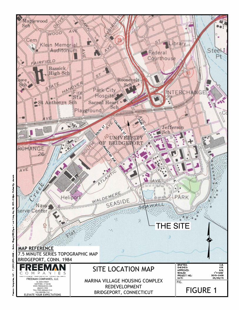
FIG.
BRIDGEPORT, CONNECTICUT
FREEMAN COMPANIES, LLC36 JOHN STREET
HARTFORD, CT 06106WWW.FREEMANCOS.COM
(860)251-9550TOLL FREE:(800)604-5141
FAX:(860)986-7161
ELEVATE YOUR EXPECTATIONS
MARINA VILLAGE HOUSING COMPLEXREDEVELOPMENT FIGURE 1
SITE LOCATION MAP
MAP REFERENCE7.5 MINUTE SERIES TOPOGRAPHIC MAPBRIDGEPORT, CONN. 1984
THE SITE

MARINA VILLAGE HOUSING COMPLEX REDEVELOPMENTBRIDGEPORT, CONNECTICUT
FREEMAN COMPANIES, LLC36 JOHN STREET
HARTFORD, CT 06106WWW.FREEMANCOS.COM
(860)251-9550TOLL FREE:(800)604-5141
FAX:(860)986-7161
ELEVATE YOUR EXPECTATIONS
SUBSURFACE EXPLORATION LOCATION PLAN
FIGURE 2

Geotechnical Report Marina Village Housing Complex Redevelopment Bridgeport, Connecticut May 29, 2015
APPENDIX A
TEST BORING LOGS

0.25to
2.25
4to6
8to10
15to17
23-8-7-10
3-2-7-22
9-12-12-14
5-8-14-20
S-1
S-2
S-3
S-4
24/18
24/6
24/20
24/18
ASPHALT (1 in.)(0.1'- 0.3') POORLY GRADED GRAVEL (GP);~100% gravel, coarse; dry, black, FILL.(0.3'- 3') SILTY SAND (SM); ~75% sand, fine tocoarse, ~15% fines, ~10% gravel, fine tomedium; brown, FILL, with crushed brick.(3'- 7') SILTY SAND WITH GRAVEL (SM); ~50%sand, fine to medium, ~35% gravel, coarse,~15% fines; brown, FILL, with crushed brick,glass, black material (odor).
(7'- 16') POORLY GRADED SAND (SP); ~85%sand, medium to coarse, ~10% gravel, fine, ~5%fines; brown.
(16'- 17') SANDY SILT (ML); ~60% fines, ~40%sand, fine to medium; brown.Bottom of Exploration at 17 feet
backfillcuttings6"bentoniteseal. 1/4bag
#2 sandfor sandpack. 3bags.2"diamterPVCScreen,0.010slot size
17'bottomdepth ofboring,backfillcuttings,PVCplug
DATE START / END: 5/14/2015 - 5/14/2015
HAMMER WEIGHT (lbs): 140HAMMER TYPE: Safety Hammer
CONTRACTOR: New England Boring
GENERAL NOTES:
CORE INFO:
ABBREVIATIONS:mpf = Minute per FootOD = Outside Diameter
PID = Photoionization DetectorDP = Direct Push Sample
HAMMER DROP (inch): 30
EQUIPMENT:
CASING ID/OD: N/A / N/A
DRILLER: Mike St. John
TOTAL DEPTH (FT): 17.0
AUGER ID/OD: 4.25 in / N/A
U = Undistrubed Tube Sample WOH = Weight of Hammer Sv = Pocket Torvane Shear StrengthRQD = Rock Quality Designation
SC = Sonic CoreWOR = Weight of Rods Qv = Pocket Penetrometer Strength
Drilling Information
LOGGED BY (Person): J. Herpich
EXPLORATION TYPE/METHOD: Hollow Stem Auger
WATER LEVEL DEPTHS (ft): 8.00 5/14/2015 6.40 5/18/2015
ID = Inside Diameter bpf = Blows per FootC = Rock Core Fv = Field Vane Shear Strength
Pen. = Penetration Length S = Split Spoon NA, NM = Not Applicable, Not MeasuredRec. = Recovery Length
Depth(ft)
GR
AP
HIC
LO
G
H20Depth
SAMPLE INFORMATION
BlowsCount
orRQD
Elev.(ft) Sample
No.
Pen./Rec.(in)T
ype
PROJECT NAME: Marina Village Housing Complex RedevelopementCITY/STATE: Bridgeport, CT
TestData
CasingPen.(bpf)
orCoreRate(mpf)
Stratification lines represent approximateboundary between soil types, transitions may begradual. Water level readings have been madeat times and under conditions stated.Fluctuations of groundwater may occur due toother factors than those present at the timemeasurements were made.
LOGGED BY (Consultant): Freeman Companies, LLC
SampleDescription &Classification
PROJECT NUMBER: 2015-0408
Depth(ft)
5
10
15
20
Freeman Companies, LLC36 John StreetHartford, CT 06102(860) 251-9550www.freemancos.comF
RE
EM
AN
CO
MP
AN
IES
PR
OJE
CT
20
15-0
408
- M
AR
INA
VIL
LAG
E.G
PJ
GIN
T S
TD
US
LA
B.G
DT
5/2
9/1
5
OFFSET:STATION CENTERLINE:HORIZONTAL DATUM:
VERTICAL DATUM:LOCATION: PAGE 1 of 1
EASTING:NORTHING:Exploration Location
STATION:
EXPLORATION
ESTIMATED GROUND SURFACE ELEV. (FT):B-1/MW-3
WELLCONSTRUCTION
DETAILS

0to2
4to6
8to10
15to17
2-6-13-6
2-1-1-3
8-10-10-11
15-14-16-18
S-1
S-2
S-3
S-4
24/19
24/23
24/24
24/24
TOPSOIL
(1'- 1.5') POORLY GRADED SAND WITHGRAVEL (SP); ~70% sand, fine to coarse, ~25%gravel, fine to coarse, ~5% fines; tan, FILL,asphalt pieces.(1.5'- 3') POORLY GRADED SAND WITHGRAVEL (SP); ~50% sand, fine to coarse, ~45%gravel, fine to coarse, ~5% fines; brown, FILL,crushed concrete and asphalt.(3'- 4.9') SILTY SAND (SM); ~70% sand, fine tocoarse, ~30% fines; brown.(4.9'- 16.3') POORLY GRADED SAND (SP);~95% sand, medium to coarse, ~5% fines; tan.
(16.3'- 17') SILT (ML); ~80% fines, ~20% sand;wet, light brown.Bottom of Exploration at 17 feet
DATE START / END: 5/12/2015 - 5/12/2015
HAMMER WEIGHT (lbs): 140HAMMER TYPE: Safety Hammer
CONTRACTOR: New England Boring
GENERAL NOTES:
CORE INFO:
ABBREVIATIONS:mpf = Minute per FootOD = Outside Diameter
PID = Photoionization DetectorDP = Direct Push Sample
HAMMER DROP (inch): 30
EQUIPMENT:
CASING ID/OD: N/A / N/A
DRILLER: Mike St. John
TOTAL DEPTH (FT): 17.0
AUGER ID/OD: N/A / N/A
U = Undistrubed Tube Sample WOH = Weight of Hammer Sv = Pocket Torvane Shear StrengthRQD = Rock Quality Designation
SC = Sonic CoreWOR = Weight of Rods Qv = Pocket Penetrometer Strength
Drilling Information
LOGGED BY (Person): J. Herpich
EXPLORATION TYPE/METHOD: Hollow Stem Auger
WATER LEVEL DEPTHS (ft): 8.00 5/12/2015
ID = Inside Diameter bpf = Blows per FootC = Rock Core Fv = Field Vane Shear Strength
Pen. = Penetration Length S = Split Spoon NA, NM = Not Applicable, Not MeasuredRec. = Recovery Length
Depth(ft)
GR
AP
HIC
LO
G
H20Depth
SAMPLE INFORMATION
BlowsCount
orRQD
Elev.(ft) Sample
No.
Pen./Rec.(in)T
ype
PROJECT NAME: Marina Village Housing Complex RedevelopementCITY/STATE: Bridgeport, CT
TestData
CasingPen.(bpf)
orCoreRate(mpf)
Stratification lines represent approximateboundary between soil types, transitions may begradual. Water level readings have been madeat times and under conditions stated.Fluctuations of groundwater may occur due toother factors than those present at the timemeasurements were made.
LOGGED BY (Consultant): Freeman Companies, LLC
SampleDescription &Classification
PROJECT NUMBER: 2015-0408
RemarksDepth(ft)
5
10
15
20
Freeman Companies, LLC36 John StreetHartford, CT 06102(860) 251-9550www.freemancos.comF
RE
EM
AN
CO
MP
AN
IES
PR
OJE
CT
20
15-0
408
- M
AR
INA
VIL
LAG
E.G
PJ
GIN
T S
TD
US
LA
B.G
DT
5/2
9/1
5
OFFSET:STATION CENTERLINE:HORIZONTAL DATUM:
VERTICAL DATUM:LOCATION: PAGE 1 of 1
EASTING:NORTHING:Exploration Location
STATION:
EXPLORATION
ESTIMATED GROUND SURFACE ELEV. (FT):B-2

0.2to2.2
4to6
8to10
15to17
8-8-5-9
2-4-3-4
6-5-7-8
22-24-27-28
S-1
S-2
S-3
S-4
24/13
24/14
24/24
24/24
ASPHALT (2 in.)(0.2'- 2.2') POORLY GRADED SAND WITHGRAVEL (SP); ~60% sand, medium to coarse,~30% gravel, fine, ~10% fines; dry, tan, FILL,conrete, asphalt and brick pieces (fill).(2.2'- 5') SILTY SAND (SM); ~60% sand, fine tocoarse, ~25% gravel, fine, ~15% fines; dry, tan,FILL, conrete, asphalt and brick pieces (fill).
(5'- 12.5') POORLY GRADED SAND (SP); ~95%sand, coarse, ~5% fines; dry, tan, FILL.
(12.5'- 16.4') POORLY GRADED SAND (SP);~85% sand, medium to coarse, ~10% gravel,fine, ~5% fines; wet, brown.
(16.4'- 17') SILT (ML); ~60% fines, ~40% sand;wet, light brown.Bottom of Exploration at 17 feet
DATE START / END: 5/12/2015 - 5/12/2015
HAMMER WEIGHT (lbs): 140HAMMER TYPE: Safety Hammer
CONTRACTOR: New England Boring
GENERAL NOTES:
CORE INFO:
ABBREVIATIONS:mpf = Minute per FootOD = Outside Diameter
PID = Photoionization DetectorDP = Direct Push Sample
HAMMER DROP (inch): 30
EQUIPMENT:
CASING ID/OD: N/A / N/A
DRILLER: Mike St. John
TOTAL DEPTH (FT): 17.0
AUGER ID/OD: N/A / N/A
U = Undistrubed Tube Sample WOH = Weight of Hammer Sv = Pocket Torvane Shear StrengthRQD = Rock Quality Designation
SC = Sonic CoreWOR = Weight of Rods Qv = Pocket Penetrometer Strength
Drilling Information
LOGGED BY (Person): J. Herpich
EXPLORATION TYPE/METHOD: Hollow Stem Auger
WATER LEVEL DEPTHS (ft): 8.00 5/12/2015
ID = Inside Diameter bpf = Blows per FootC = Rock Core Fv = Field Vane Shear Strength
Pen. = Penetration Length S = Split Spoon NA, NM = Not Applicable, Not MeasuredRec. = Recovery Length
Depth(ft)
GR
AP
HIC
LO
G
H20Depth
SAMPLE INFORMATION
BlowsCount
orRQD
Elev.(ft) Sample
No.
Pen./Rec.(in)T
ype
PROJECT NAME: Marina Village Housing Complex RedevelopementCITY/STATE: Bridgeport, CT
TestData
CasingPen.(bpf)
orCoreRate(mpf)
Stratification lines represent approximateboundary between soil types, transitions may begradual. Water level readings have been madeat times and under conditions stated.Fluctuations of groundwater may occur due toother factors than those present at the timemeasurements were made.
LOGGED BY (Consultant): Freeman Companies, LLC
SampleDescription &Classification
PROJECT NUMBER: 2015-0408
RemarksDepth(ft)
5
10
15
20
Freeman Companies, LLC36 John StreetHartford, CT 06102(860) 251-9550www.freemancos.comF
RE
EM
AN
CO
MP
AN
IES
PR
OJE
CT
20
15-0
408
- M
AR
INA
VIL
LAG
E.G
PJ
GIN
T S
TD
US
LA
B.G
DT
5/2
9/1
5
OFFSET:STATION CENTERLINE:HORIZONTAL DATUM:
VERTICAL DATUM:LOCATION: PAGE 1 of 1
EASTING:NORTHING:Exploration Location
STATION:
EXPLORATION
ESTIMATED GROUND SURFACE ELEV. (FT):B-3

0.1to2.1
2to4
4to6
8to10
15to17
20-9-10-4
4-2-3-3
4-6-8-12
4-9-14-43
18-13-16-18
S-1
S-2
S-3
S-4
S-5
24/2
24/9
24/15
24/24
24/14
ASPHALT (1 in.)(0.1'- 0.4') POORLY GRADED GRAVEL (GP);~60% gravel, medium to coarse, ~40% sand,fine; FILL.(0.4'- 2.1') POORLY GRADED GRAVEL WITHSAND (GP); ~60% gravel, medium to coarse,~40% sand, fine; dry, black, FILL.(2.1'- 2.5') SILTY SAND (SM); ~60% sand, fine,~40% fines; dry, tan, FILL.(2.5'- 4') POORLY GRADED SAND WITH SILTAND GRAVEL (SM); ~70% sand, fine, ~20%fines, ~10% gravel, coarse, angular; dry, brown,FILL, asphalt pieces.(4'- 9') POORLY GRADED SAND WITHGRAVEL (SP); ~90% sand, fine to coarse, ~10%gravel, fine; wet, tan.
(9'- 12.5') SILTY SAND (SM); ~50% sand, fine tomedium, ~40% fines, ~10% gravel, fine tocoarse; wet, light brown.
(12.5'- 17') SILTY SAND WITH GRAVEL (SC);~65% sand, medium to coarse, ~20% fines,~15% gravel, fine to coarse; wet, gray.
Bottom of Exploration at 17 feet
backfillcuttings6"bentoniteseal. 1/4bag
# sandfor sandpack2"diamterPVCScreen,0.010slot size
17'bottomdepth ofboring,backfillcuttings,PVCplug
DATE START / END: 5/13/2015 - 5/13/2015
HAMMER WEIGHT (lbs): 140HAMMER TYPE: Safety Hammer
CONTRACTOR: New England Boring
GENERAL NOTES:
CORE INFO:
ABBREVIATIONS:mpf = Minute per FootOD = Outside Diameter
PID = Photoionization DetectorDP = Direct Push Sample
HAMMER DROP (inch): 30
EQUIPMENT:
CASING ID/OD: N/A / N/A
DRILLER: Mike St. John
TOTAL DEPTH (FT): 17.0
AUGER ID/OD: 4.25 in / N/A
U = Undistrubed Tube Sample WOH = Weight of Hammer Sv = Pocket Torvane Shear StrengthRQD = Rock Quality Designation
SC = Sonic CoreWOR = Weight of Rods Qv = Pocket Penetrometer Strength
Drilling Information
LOGGED BY (Person): J. Herpich
EXPLORATION TYPE/METHOD: Hollow Stem Auger
WATER LEVEL DEPTHS (ft): 8.00 5/13/2015 7.56 5/18/2015
ID = Inside Diameter bpf = Blows per FootC = Rock Core Fv = Field Vane Shear Strength
Pen. = Penetration Length S = Split Spoon NA, NM = Not Applicable, Not MeasuredRec. = Recovery Length
Depth(ft)
GR
AP
HIC
LO
G
H20Depth
SAMPLE INFORMATION
BlowsCount
orRQD
Elev.(ft) Sample
No.
Pen./Rec.(in)T
ype
PROJECT NAME: Marina Village Housing Complex RedevelopementCITY/STATE: Bridgeport, CT
TestData
CasingPen.(bpf)
orCoreRate(mpf)
Stratification lines represent approximateboundary between soil types, transitions may begradual. Water level readings have been madeat times and under conditions stated.Fluctuations of groundwater may occur due toother factors than those present at the timemeasurements were made.
LOGGED BY (Consultant): Freeman Companies, LLC
SampleDescription &Classification
PROJECT NUMBER: 2015-0408
Depth(ft)
5
10
15
20
Freeman Companies, LLC36 John StreetHartford, CT 06102(860) 251-9550www.freemancos.comF
RE
EM
AN
CO
MP
AN
IES
PR
OJE
CT
20
15-0
408
- M
AR
INA
VIL
LAG
E.G
PJ
GIN
T S
TD
US
LA
B.G
DT
5/2
9/1
5
OFFSET:STATION CENTERLINE:HORIZONTAL DATUM:
VERTICAL DATUM:LOCATION: PAGE 1 of 1
EASTING:NORTHING:Exploration Location
STATION:
EXPLORATION
ESTIMATED GROUND SURFACE ELEV. (FT):B-4/MW-1
WELLCONSTRUCTION
DETAILS

0to2
2to4
4to6
6to8
2-6-13-17
25-15-32-23
17-8-5-6
4-3-3-18
S-1
S-2
S-3
S-4
24/21
24/22
24/19
24/24
TOPSOIL (13 in.)
(1.1'- 2') SILTY SAND (SM); ~50% sand, ~50%fines, ~0% gravel; dry, dark brown, FILL, Piecesof brick and asphalt.(2'- 2.75') WELL GRADED SAND (SW); ~100%sand, fine to coarse; dry, light brown, FILL.(2.75'- 4.8') SILTY SAND (SM); ~80% sand, fine,~20% fines; dry, dark brown, FILL, with brick,asphalt, roof felt, and concrete.(4.8'- 5.4') SANDY SILT (ML); ~70% fines, ~30%sand, fine to coarse; moist, dark brown, FILL.(5.4'- 6') SILTY SAND (SM); ~80% sand, fine tocoarse, ~20% fines; moist, tan, FILL.(6'- 6.4') SANDY SILT (ML); ~70% fines, ~30%sand, fine to coarse; wet, dark brown, FILL.(6.4'- 6.7') SILTY SAND (SM); ~80% sand,medium to coarse, ~20% fines; wet, tan, FILL.(6.7'- 7.6') SILTY SAND WITH GRAVEL (SM);~50% sand, medium to coarse, ~30% fines,~20% gravel, fine; wet, tan, FILL.(7.6'- 8') SILTY SAND (SM); ~85% sand, fine tomedium, ~15% fines; wet, tan.Bottom of Exploration at 8 feet
DATE START / END: 5/12/2015 - 5/12/2015
HAMMER WEIGHT (lbs): 140HAMMER TYPE: Safety Hammer
CONTRACTOR: New England Boring
GENERAL NOTES:
CORE INFO:
ABBREVIATIONS:mpf = Minute per FootOD = Outside Diameter
PID = Photoionization DetectorDP = Direct Push Sample
HAMMER DROP (inch): 30
EQUIPMENT:
CASING ID/OD: N/A / N/A
DRILLER: Mike St. John
TOTAL DEPTH (FT): 8.0
AUGER ID/OD: N/A / N/A
U = Undistrubed Tube Sample WOH = Weight of Hammer Sv = Pocket Torvane Shear StrengthRQD = Rock Quality Designation
SC = Sonic CoreWOR = Weight of Rods Qv = Pocket Penetrometer Strength
Drilling Information
LOGGED BY (Person): J. Herpich
EXPLORATION TYPE/METHOD: Hollow Stem Auger
WATER LEVEL DEPTHS (ft): 6.50 5/12/2015
ID = Inside Diameter bpf = Blows per FootC = Rock Core Fv = Field Vane Shear Strength
Pen. = Penetration Length S = Split Spoon NA, NM = Not Applicable, Not MeasuredRec. = Recovery Length
Depth(ft)
GR
AP
HIC
LO
G
H20Depth
SAMPLE INFORMATION
BlowsCount
orRQD
Elev.(ft) Sample
No.
Pen./Rec.(in)T
ype
PROJECT NAME: Marina Village Housing Complex RedevelopementCITY/STATE: Bridgeport, CT
TestData
CasingPen.(bpf)
orCoreRate(mpf)
Stratification lines represent approximateboundary between soil types, transitions may begradual. Water level readings have been madeat times and under conditions stated.Fluctuations of groundwater may occur due toother factors than those present at the timemeasurements were made.
LOGGED BY (Consultant): Freeman Companies, LLC
SampleDescription &Classification
PROJECT NUMBER: 2015-0408
RemarksDepth(ft)
5
10
15
20
Freeman Companies, LLC36 John StreetHartford, CT 06102(860) 251-9550www.freemancos.comF
RE
EM
AN
CO
MP
AN
IES
PR
OJE
CT
20
15-0
408
- M
AR
INA
VIL
LAG
E.G
PJ
GIN
T S
TD
US
LA
B.G
DT
5/2
9/1
5
OFFSET:STATION CENTERLINE:HORIZONTAL DATUM:
VERTICAL DATUM:LOCATION: PAGE 1 of 1
EASTING:NORTHING:Exploration Location
STATION:
EXPLORATION
ESTIMATED GROUND SURFACE ELEV. (FT):B-5

0to2
2to4
4to6
6to8
8to10
13-17-11-14
13-22-105-30
15-2-2-2
2-1-1-1
8-10-15-19
S-1
S-2
S-3
S-4
S-5
24/19
24/19
24/21
24/19
24/24
ASPHALT (2 in.)(0.2'- 4.7') SILTY SAND WITH GRAVEL (SM);~65% sand, fine to coarse, ~20% fines, ~15%gravel, fine to coarse; dark brown, FILL, withconcrete, brick, and black material.
(4.7'- 4.8') SILT WITH SAND (ML); ~50% sand,fine, ~50% fines; tan, FILL.(4.8'- 6') SILT WITH SAND (ML); ~70% sand,fine to coarse, ~30% fines; gray, FILL, withconcrete, brick, black material, unknown whitematerial,.(6'- 7.6') SILTY SAND (SM); ~70% sand, fine tocoarse, ~30% fines; tan, FILL.(7.6'- 8.5') SILTY SAND (SM); ~85% sand, fine tocoarse, ~15% fines; gray, FILL, with concrete,brick, black material, unknown white material,.(8.5'- 10') POORLY GRADED SAND (SP); ~98%sand, fine to coarse, ~2% fines; tan.Bottom of Exploration at 10 feet
DATE START / END: 5/13/2015 - 5/13/2015
HAMMER WEIGHT (lbs): 140HAMMER TYPE: Safety Hammer
CONTRACTOR: New England Boring
GENERAL NOTES:
CORE INFO:
ABBREVIATIONS:mpf = Minute per FootOD = Outside Diameter
PID = Photoionization DetectorDP = Direct Push Sample
HAMMER DROP (inch): 30
EQUIPMENT:
CASING ID/OD: N/A / N/A
DRILLER: Mike St. John
TOTAL DEPTH (FT): 10.0
AUGER ID/OD: N/A / N/A
U = Undistrubed Tube Sample WOH = Weight of Hammer Sv = Pocket Torvane Shear StrengthRQD = Rock Quality Designation
SC = Sonic CoreWOR = Weight of Rods Qv = Pocket Penetrometer Strength
Drilling Information
LOGGED BY (Person): J. Herpich
EXPLORATION TYPE/METHOD: Hollow Stem Auger
WATER LEVEL DEPTHS (ft): 7.00 5/13/2015
ID = Inside Diameter bpf = Blows per FootC = Rock Core Fv = Field Vane Shear Strength
Pen. = Penetration Length S = Split Spoon NA, NM = Not Applicable, Not MeasuredRec. = Recovery Length
Depth(ft)
GR
AP
HIC
LO
G
H20Depth
SAMPLE INFORMATION
BlowsCount
orRQD
Elev.(ft) Sample
No.
Pen./Rec.(in)T
ype
PROJECT NAME: Marina Village Housing Complex RedevelopementCITY/STATE: Bridgeport, CT
TestData
CasingPen.(bpf)
orCoreRate(mpf)
Stratification lines represent approximateboundary between soil types, transitions may begradual. Water level readings have been madeat times and under conditions stated.Fluctuations of groundwater may occur due toother factors than those present at the timemeasurements were made.
LOGGED BY (Consultant): Freeman Companies, LLC
SampleDescription &Classification
PROJECT NUMBER: 2015-0408
RemarksDepth(ft)
5
10
15
20
Freeman Companies, LLC36 John StreetHartford, CT 06102(860) 251-9550www.freemancos.comF
RE
EM
AN
CO
MP
AN
IES
PR
OJE
CT
20
15-0
408
- M
AR
INA
VIL
LAG
E.G
PJ
GIN
T S
TD
US
LA
B.G
DT
5/2
9/1
5
OFFSET:STATION CENTERLINE:HORIZONTAL DATUM:
VERTICAL DATUM:LOCATION: PAGE 1 of 1
EASTING:NORTHING:Exploration Location
STATION:
EXPLORATION
ESTIMATED GROUND SURFACE ELEV. (FT):B-6

0to2
2to4
4to6
6to8
9-21-21-39
11-8-4-5
2-2-2-2
4-16-21-14
S-1
S-2
S-3
S-4
24/17
24/24
24/24
24/20
APHALT (3 in.)(0.3'- 4.4') SILTY SAND WITH GRAVEL (SM);~65% sand, fine to medium, ~20% gravel, fine tocoarse, ~15% fines; brown, FILL, with asphalt,plastic, and black materials.
(4.4'- 6') SILTY SAND WITH GRAVEL (SM);~60% sand, fine to medium, ~20% gravel, fine,~20% fines; moist, tan.
(6'- 6.5') SILTY SAND WITH GRAVEL (SM);~70% sand, fine, ~20% fines, ~10% gravel,medium to coarse; wet.(6.5'- 8') POORLY GRADED SAND (SP); ~95%sand, medium to coarse, ~5% fines; wet, tan.Bottom of Exploration at 8 feet
DATE START / END: 5/12/2015 - 5/12/2015
HAMMER WEIGHT (lbs): 140HAMMER TYPE: Safety Hammer
CONTRACTOR: New England Boring
GENERAL NOTES:
CORE INFO:
ABBREVIATIONS:mpf = Minute per FootOD = Outside Diameter
PID = Photoionization DetectorDP = Direct Push Sample
HAMMER DROP (inch): 30
EQUIPMENT:
CASING ID/OD: N/A / N/A
DRILLER: Mike St. John
TOTAL DEPTH (FT): 8.0
AUGER ID/OD: N/A / N/A
U = Undistrubed Tube Sample WOH = Weight of Hammer Sv = Pocket Torvane Shear StrengthRQD = Rock Quality Designation
SC = Sonic CoreWOR = Weight of Rods Qv = Pocket Penetrometer Strength
Drilling Information
LOGGED BY (Person): J. Herpich
EXPLORATION TYPE/METHOD: Hollow Stem Auger
WATER LEVEL DEPTHS (ft): 6.00 5/12/2015
ID = Inside Diameter bpf = Blows per FootC = Rock Core Fv = Field Vane Shear Strength
Pen. = Penetration Length S = Split Spoon NA, NM = Not Applicable, Not MeasuredRec. = Recovery Length
Depth(ft)
GR
AP
HIC
LO
G
H20Depth
SAMPLE INFORMATION
BlowsCount
orRQD
Elev.(ft) Sample
No.
Pen./Rec.(in)T
ype
PROJECT NAME: Marina Village Housing Complex RedevelopementCITY/STATE: Bridgeport, CT
TestData
CasingPen.(bpf)
orCoreRate(mpf)
Stratification lines represent approximateboundary between soil types, transitions may begradual. Water level readings have been madeat times and under conditions stated.Fluctuations of groundwater may occur due toother factors than those present at the timemeasurements were made.
LOGGED BY (Consultant): Freeman Companies, LLC
SampleDescription &Classification
PROJECT NUMBER: 2015-0408
RemarksDepth(ft)
5
10
15
20
Freeman Companies, LLC36 John StreetHartford, CT 06102(860) 251-9550www.freemancos.comF
RE
EM
AN
CO
MP
AN
IES
PR
OJE
CT
20
15-0
408
- M
AR
INA
VIL
LAG
E.G
PJ
GIN
T S
TD
US
LA
B.G
DT
5/2
9/1
5
OFFSET:STATION CENTERLINE:HORIZONTAL DATUM:
VERTICAL DATUM:LOCATION: PAGE 1 of 1
EASTING:NORTHING:Exploration Location
STATION:
EXPLORATION
ESTIMATED GROUND SURFACE ELEV. (FT):B-7

0to2
2to4
4to6
6to8
8to10
10to12
9-12-8-16
5-5-4-4
7-7-9-8
5-5-4-3
100/2"
11-15-16-21
S-1
S-2
S-3
S-4
S-5
S-6
24
24
24
24
24
24
TOPSOIL (6 in.)(0.5'- 2') POORLY GRADED SAND WITHGRAVEL (SP); ~60% sand, fine to coarse, ~30%gravel, fine to coarse, ~10% fines; dry, FILL, withbrick, concrete, and black material.(2'- 4') POORLY GRADED SAND WITHGRAVEL (SP); ~70% sand, medium to coarse,~30% gravel, fine to coarse; dry, tan, FILL, blackmaterial.(4'- 7') POORLY GRADED SAND WITHGRAVEL (SP); ~75% sand, fine to coarse, ~20%gravel, fine to coarse, ~5% fines; moist, darkbrown, FILL, with brick, black material, unknownwhite material.(7'- 10') SILTY SAND WITH GRAVEL (SM);~60% sand, fine to coarse, ~20% gravel, fine tocoarse, ~20% fines; wet, dark brown, FILL, withbrick, black material, unknown white material.
(10'- 12') SILTY SAND WITH GRAVEL (SM);~55% sand, fine to coarse, ~30% gravel, fine tocoarse, ~15% fines; wet, brown.
Bottom of Exploration at 12 feet
DATE START / END: 5/13/2015 - 5/13/2015
HAMMER WEIGHT (lbs): 140HAMMER TYPE: Safety Hammer
CONTRACTOR: New England Boring
GENERAL NOTES:
CORE INFO:
ABBREVIATIONS:mpf = Minute per FootOD = Outside Diameter
PID = Photoionization DetectorDP = Direct Push Sample
HAMMER DROP (inch): 30
EQUIPMENT:
CASING ID/OD: N/A / N/A
DRILLER: Mike St. John
TOTAL DEPTH (FT): 12.0
AUGER ID/OD: N/A / N/A
U = Undistrubed Tube Sample WOH = Weight of Hammer Sv = Pocket Torvane Shear StrengthRQD = Rock Quality Designation
SC = Sonic CoreWOR = Weight of Rods Qv = Pocket Penetrometer Strength
Drilling Information
LOGGED BY (Person): J. Herpich
EXPLORATION TYPE/METHOD: Hollow Stem Auger
WATER LEVEL DEPTHS (ft): 6.50 5/13/2015
ID = Inside Diameter bpf = Blows per FootC = Rock Core Fv = Field Vane Shear Strength
Pen. = Penetration Length S = Split Spoon NA, NM = Not Applicable, Not MeasuredRec. = Recovery Length
Depth(ft)
GR
AP
HIC
LO
G
H20Depth
SAMPLE INFORMATION
BlowsCount
orRQD
Elev.(ft) Sample
No.
Pen./Rec.(in)T
ype
PROJECT NAME: Marina Village Housing Complex RedevelopementCITY/STATE: Bridgeport, CT
TestData
CasingPen.(bpf)
orCoreRate(mpf)
Stratification lines represent approximateboundary between soil types, transitions may begradual. Water level readings have been madeat times and under conditions stated.Fluctuations of groundwater may occur due toother factors than those present at the timemeasurements were made.
LOGGED BY (Consultant): Freeman Companies, LLC
SampleDescription &Classification
PROJECT NUMBER: 2015-0408
RemarksDepth(ft)
5
10
15
20
Freeman Companies, LLC36 John StreetHartford, CT 06102(860) 251-9550www.freemancos.comF
RE
EM
AN
CO
MP
AN
IES
PR
OJE
CT
20
15-0
408
- M
AR
INA
VIL
LAG
E.G
PJ
GIN
T S
TD
US
LA
B.G
DT
5/2
9/1
5
OFFSET:STATION CENTERLINE:HORIZONTAL DATUM:
VERTICAL DATUM:LOCATION: PAGE 1 of 1
EASTING:NORTHING:Exploration Location
STATION:
EXPLORATION
ESTIMATED GROUND SURFACE ELEV. (FT):B-8

0to2
4to6
8to10
15to17
14-16-24-24
14-19-17-21
21-30-39-33
32-41-72-100
S-1
S-2
S-3
S-4
24/20
24/17
24/18
24/22
(0'- 9.5') SILTY SAND WITH GRAVEL (SM);~55% sand, fine to coarse, ~30% fines, ~15%gravel, fine to medium; moist, brown.
(9.5'- 10') SILTY SAND WITH GRAVEL (SM);~55% sand, fine to coarse, ~30% fines, ~15%gravel, fine to medium; moist, black, odor.(10'- 17') SILTY SAND WITH GRAVEL (SM);~55% sand, fine to coarse, ~30% fines, ~15%gravel, fine to medium; moist, brown.
Bottom of Exploration at 17 feet
backfillcuttings6"bentoniteseal. 1/4bag.
#2 sandfor sandpack.
2"diamterPVCScreen,0.010slot size.
17'bottomdepth ofboring,backfillcuttings,PVCplug
DATE START / END: 5/14/2015 - 5/14/2015
HAMMER WEIGHT (lbs): 140HAMMER TYPE: Safety Hammer
CONTRACTOR: New England Boring
GENERAL NOTES:
CORE INFO:
ABBREVIATIONS:mpf = Minute per FootOD = Outside Diameter
PID = Photoionization DetectorDP = Direct Push Sample
HAMMER DROP (inch): 30
EQUIPMENT:
CASING ID/OD: N/A / N/A
DRILLER: Mike St. John
TOTAL DEPTH (FT): 17.0
AUGER ID/OD: 4.25 in / N/A
U = Undistrubed Tube Sample WOH = Weight of Hammer Sv = Pocket Torvane Shear StrengthRQD = Rock Quality Designation
SC = Sonic CoreWOR = Weight of Rods Qv = Pocket Penetrometer Strength
Drilling Information
LOGGED BY (Person): J. Herpich
EXPLORATION TYPE/METHOD: Hollow Stem Auger
WATER LEVEL DEPTHS (ft): 6.41 5/18/2015
ID = Inside Diameter bpf = Blows per FootC = Rock Core Fv = Field Vane Shear Strength
Pen. = Penetration Length S = Split Spoon NA, NM = Not Applicable, Not MeasuredRec. = Recovery Length
Depth(ft)
GR
AP
HIC
LO
G
H20Depth
SAMPLE INFORMATION
BlowsCount
orRQD
Elev.(ft) Sample
No.
Pen./Rec.(in)T
ype
PROJECT NAME: Marina Village Housing Complex RedevelopementCITY/STATE: Bridgeport, CT
TestData
CasingPen.(bpf)
orCoreRate(mpf)
Stratification lines represent approximateboundary between soil types, transitions may begradual. Water level readings have been madeat times and under conditions stated.Fluctuations of groundwater may occur due toother factors than those present at the timemeasurements were made.
LOGGED BY (Consultant): Freeman Companies, LLC
SampleDescription &Classification
PROJECT NUMBER: 2015-0408
Depth(ft)
10
15
20
Freeman Companies, LLC36 John StreetHartford, CT 06102(860) 251-9550www.freemancos.comF
RE
EM
AN
CO
MP
AN
IES
PR
OJE
CT
20
15-0
408
- M
AR
INA
VIL
LAG
E.G
PJ
GIN
T S
TD
US
LA
B.G
DT
5/2
9/1
5
OFFSET:STATION CENTERLINE:HORIZONTAL DATUM:
VERTICAL DATUM:LOCATION: PAGE 1 of 1
EASTING:NORTHING:Exploration Location
STATION:
EXPLORATION
ESTIMATED GROUND SURFACE ELEV. (FT):B-9/MW-2
WELLCONSTRUCTION
DETAILS

0to2
4to6
8to10
15to17
20to
20.7
11-6-6-5
20-17-20-16
16-32-30-40
57-77-59-129
30-140/2"
S-1
S-2
S-3
S-4
S-5
24/10
24/24
24/20
24/24
8/8
(0'- 3.5') SILTY SAND WITH GRAVEL (SM);~40% sand, fine to coarse, ~40% fines, ~20%gravel, fine to medium; dry, brown.
(3.5'- 8.5') SILTY SAND WITH GRAVEL (SM);~40% sand, fine to medium, ~40% fines, ~20%gravel, fine to coarse; dry, brown.
(8.5'- 20.7') SILTY SAND WITH GRAVEL (SM);~60% sand, fine to coarse, ~20% gravel, fine tomedium, ~20% fines; wet, brown.
Bottom of Exploration at 20.67 feet
DATE START / END: 5/13/2015 - 5/13/2015
HAMMER WEIGHT (lbs): 140HAMMER TYPE: Safety Hammer
CONTRACTOR: New England Boring
GENERAL NOTES:
CORE INFO:
ABBREVIATIONS:mpf = Minute per FootOD = Outside Diameter
PID = Photoionization DetectorDP = Direct Push Sample
HAMMER DROP (inch): 30
EQUIPMENT:
CASING ID/OD: N/A / N/A
DRILLER: Mike St. John
TOTAL DEPTH (FT): 20.7
AUGER ID/OD: N/A / N/A
U = Undistrubed Tube Sample WOH = Weight of Hammer Sv = Pocket Torvane Shear StrengthRQD = Rock Quality Designation
SC = Sonic CoreWOR = Weight of Rods Qv = Pocket Penetrometer Strength
Drilling Information
LOGGED BY (Person): J. Herpich
EXPLORATION TYPE/METHOD: Hollow Stem Auger
WATER LEVEL DEPTHS (ft): 11.00 5/13/2015
ID = Inside Diameter bpf = Blows per FootC = Rock Core Fv = Field Vane Shear Strength
Pen. = Penetration Length S = Split Spoon NA, NM = Not Applicable, Not MeasuredRec. = Recovery Length
Depth(ft)
GR
AP
HIC
LO
G
H20Depth
SAMPLE INFORMATION
BlowsCount
orRQD
Elev.(ft) Sample
No.
Pen./Rec.(in)T
ype
PROJECT NAME: Marina Village Housing Complex RedevelopementCITY/STATE: Bridgeport, CT
TestData
CasingPen.(bpf)
orCoreRate(mpf)
Stratification lines represent approximateboundary between soil types, transitions may begradual. Water level readings have been madeat times and under conditions stated.Fluctuations of groundwater may occur due toother factors than those present at the timemeasurements were made.
LOGGED BY (Consultant): Freeman Companies, LLC
SampleDescription &Classification
PROJECT NUMBER: 2015-0408
RemarksDepth(ft)
5
10
15
20
Freeman Companies, LLC36 John StreetHartford, CT 06102(860) 251-9550www.freemancos.comF
RE
EM
AN
CO
MP
AN
IES
PR
OJE
CT
20
15-0
408
- M
AR
INA
VIL
LAG
E.G
PJ
GIN
T S
TD
US
LA
B.G
DT
5/2
9/1
5
OFFSET:STATION CENTERLINE:HORIZONTAL DATUM:
VERTICAL DATUM:LOCATION: PAGE 1 of 1
EASTING:NORTHING:Exploration Location
STATION:
EXPLORATION
ESTIMATED GROUND SURFACE ELEV. (FT):B-10

Geotechnical Report Marina Village Housing Complex Redevelopment Bridgeport, Connecticut May 29, 2015
APPENDIX B
LABORATORY TEST RESULTS

Client: Freeman Companies, LLCProject: Marina Village Housing RedevelopmentLocation: Bridgeport, CT Project No: GTX-303192Boring ID: B-2Sample ID: S3Depth : 8-10 ft
Sample Type: bagTest Date: 05/27/15Test Id: 333328
Tested By: jbrChecked By: emm
Test Comment: ---Sample Description: Moist, brownish yellow sand with siltSample Comment: ---
Particle Size Analysis - ASTM D422
printed 5/27/2015 5:10:26 PM
0
10
20
30
40
50
60
70
80
90
100
0.0010.010.11101001000
Per
cent
Fin
er
Grain Size (mm)
#4
#10
#20
#40
#60
#10
0
#20
0
% Cobble
---
% Gravel
0.0
% Sand
94.7
% Silt & Clay Size
5.3
Sieve Name Sieve Size, mm Percent Finer Spec. Percent Complies
#4
#10
#20
#40
#60
#100
#200
4.75
2.00
0.85
0.42
0.25
0.15
0.075
100
100
98
87
61
28
5.3
CoefficientsD =0.4112 mm85
D =0.2446 mm60
D =0.2101 mm50
D =0.1550 mm30
D =0.1011 mm15
D =0.0867 mm10
C =2.821u C =1.133c
Classification ASTM N/A
AASHTO Fine Sand (A-3 (1))
Sample/Test DescriptionSand/Gravel Particle Shape : ROUNDED
Sand/Gravel Hardness : HARD

Client: Freeman Companies, LLCProject: Marina Village Housing RedevelopmentLocation: Bridgeport, CT Project No: GTX-303192Boring ID: B-4Sample ID: S5Depth : 15-17 ft
Sample Type: bagTest Date: 05/27/15Test Id: 333329
Tested By: jbrChecked By: emm
Test Comment: ---Sample Description: Moist, light gray silty sand with gravelSample Comment: ---
Particle Size Analysis - ASTM D422
printed 5/27/2015 5:10:27 PM
0
10
20
30
40
50
60
70
80
90
100
0.0010.010.11101001000
Per
cent
Fin
er
Grain Size (mm)
1 in
0.
75 in
0.5
in
0.37
5 in
#4
#10
#20
#40
#60
#10
0
#20
0
% Cobble
---
% Gravel
24.9
% Sand
56.1
% Silt & Clay Size
19.0
Sieve Name Sieve Size, mm Percent Finer Spec. Percent Complies
1 in
0.75 in
0.5 in
0.375 in
#4
#10
#20
#40
#60
#100
#200
25.00
19.00
12.50
9.50
4.75
2.00
0.85
0.42
0.25
0.15
0.075
100
89
85
82
75
71
64
54
44
31
19
CoefficientsD =12.1370 mm85
D =0.6376 mm60
D =0.3418 mm50
D =0.1382 mm30
D =N/A15
D =N/A10
C =N/Au C =N/Ac
Classification ASTM N/A
AASHTO Silty Gravel and Sand (A-2-4 (0))
Sample/Test DescriptionSand/Gravel Particle Shape : ROUNDED
Sand/Gravel Hardness : HARD

Client: Freeman Companies, LLCProject: Marina Village Housing RedevelopmentLocation: Bridgeport, CT Project No: GTX-303192Boring ID: B-7Sample ID: S4Depth : 6-8 ft
Sample Type: bagTest Date: 05/27/15Test Id: 333330
Tested By: jbrChecked By: emm
Test Comment: ---Sample Description: Moist, brownish yellow sandSample Comment: ---
Particle Size Analysis - ASTM D422
printed 5/27/2015 5:10:28 PM
0
10
20
30
40
50
60
70
80
90
100
0.0010.010.11101001000
Per
cent
Fin
er
Grain Size (mm)
0.37
5 in
#4
#10
#20
#40
#60
#10
0
#20
0
% Cobble
---
% Gravel
0.5
% Sand
95.6
% Silt & Clay Size
3.9
Sieve Name Sieve Size, mm Percent Finer Spec. Percent Complies
0.375 in
#4
#10
#20
#40
#60
#100
#200
9.50
4.75
2.00
0.85
0.42
0.25
0.15
0.075
100
99
98
93
70
30
9
3.9
CoefficientsD =0.6636 mm85
D =0.3720 mm60
D =0.3264 mm50
D =0.2513 mm30
D =0.1739 mm15
D =0.1536 mm10
C =2.422u C =1.105c
Classification ASTM Poorly graded sand (SP)
AASHTO Fine Sand (A-3 (1))
Sample/Test DescriptionSand/Gravel Particle Shape : ---
Sand/Gravel Hardness : ---

Client: Freeman Companies, LLCProject: Marina Village Housing RedevelopmentLocation: Bridgeport, CT Project No: GTX-303192Boring ID: B-10Sample ID: S5Depth : 20-22 ft
Sample Type: bagTest Date: 05/27/15Test Id: 333331
Tested By: jbrChecked By: emm
Test Comment: ---Sample Description: Moist, brown silty sandSample Comment: ---
Particle Size Analysis - ASTM D422
printed 5/27/2015 5:10:28 PM
0
10
20
30
40
50
60
70
80
90
100
0.0010.010.11101001000
Per
cent
Fin
er
Grain Size (mm)
0.75
in
0.5
in
0.37
5 in
#4
#10
#20
#40
#60
#10
0
#20
0
% Cobble
---
% Gravel
9.4
% Sand
61.4
% Silt & Clay Size
29.2
Sieve Name Sieve Size, mm Percent Finer Spec. Percent Complies
0.75 in
0.5 in
0.375 in
#4
#10
#20
#40
#60
#100
#200
19.00
12.50
9.50
4.75
2.00
0.85
0.42
0.25
0.15
0.075
100
92
92
91
88
82
73
61
46
29
CoefficientsD =1.3240 mm85
D =0.2386 mm60
D =0.1696 mm50
D =0.0775 mm30
D =N/A15
D =N/A10
C =N/Au C =N/Ac
Classification ASTM N/A
AASHTO Silty Gravel and Sand (A-2-4 (0))
Sample/Test DescriptionSand/Gravel Particle Shape : ROUNDED
Sand/Gravel Hardness : HARD

Client: Freeman Companies, LLCProject Name: Marina Village Housing RedevelopmentProject Location: Bridgeport, CTGTX #: 303192Start Date: Tested By: jcwEnd Date: Checked By: emmBoring #: B-4/CombinedSample #: S4Depth: 6-10 ftVisual Description: Moist, yellowish brown sand with gravel
Sample Type: Remolded
Sample Information: Maximum Dry Density: --- pcfOptimum Moisture Content: --- %Compaction Test Method: ---Classification (ASTM D2487): ---Assumed Specific Gravity: 2.65
Height, inDiameter, inArea, in2
Volume, in3
Mass, gBulk Density, pcfMoisture Content, %Dry Density, pcfDegree of Saturation, %Void Ratio, e
DateReading
#Volume of Flow, cc
Time of Flow, sec
Flow Rate, cc/sec Gradient
Correction Factor
5/28 1 4.3 10 0.43 0.26 1.0235/28 2 4.3 10 0.43 0.26 1.0235/28 3 4.3 10 0.43 0.26 1.0235/28 4 4.6 10 0.46 0.31 1.0235/28 5 4.6 10 0.46 0.31 1.0235/28 6 4.6 10 0.46 0.31 1.0235/28 7 4.9 10 0.49 0.34 1.0235/28 8 4.9 10 0.49 0.34 1.0235/28 9 5.0 10 0.50 0.34 1.023
Note: This standard has been withdrawn by ASTM with no replacement.
2.1E-02
1.9E-02
---
2.1E-021.9E-02
1.8E-02
2.1E-02
1.9E-021.9E-021.8E-02
19.1
1.8E-021.8E-02
1.9E-0219.119.1
12028.393.397.0
0.993.3---
4.03
Permeability,cm/sec
12.450.11575
94.2
3.984.033.98
0.77
05/28/1505/29/15
Test specimen compacted with moderate effort at air-dried moisture content. Material >3/8-inch removed from sample prior to testing (0% of sample).
Permeability of Granular Soils (Constant Head) by ASTM D2434
Sample Preparation / Test Setup:
Parameter Initial Final
cm/sec
Temp.,oC
19.119.119.119.119.1
2.0 x 10⁻²
1.9E-022.1E-02
12.450.11239
PERMEABILITY @ 20 oC =
19.1
Permeability @20 oC, cm/sec
2.1E-022.1E-02
1.8E-021.9E-02
4.0E-034.4E-034.8E-035.2E-035.6E-036.0E-036.4E-036.8E-037.2E-037.6E-038.0E-03
0.00 0.05 0.10 0.15 0.20 0.25 0.30 0.35 0.40
Vel
ocity
, cm
/sec
Hydraulic Gradient, i
Velocity vs. Hydraulic Gradient