ggf11 semantic grid applications workshop · foreword to the ggf11 semantic grid applications...
TRANSCRIPT

GGF11Semantic Grid Applications
Workshop
HonoluluJune 10, 2004
Editors: Danius MichaelidesLuc Moreau
Coordinators: David De RoureSimon CoxGeoffrey FoxCarole Goble
Workshop organizers
The workshop is being held by the GGF Semantic Grid ResearchGroup (SEM-RG) in conjunction with the Applications and TestbedsWorking Group (APPS-RG). The Workshop Co-Chairs are:
David De Roure (Chair) Semantic Grid Research GroupGeoffrey Fox Grid Computing Environments
and Semantic Grid Research GroupsCarole Goble Semantic Grid Research GroupSimon J. Cox Applications Working Group
Proceedings
Luc Moreau (proceedings chair) University of Southampton, UKDanius Michaelides (submission chair) University of Southampton, UK
Program Committee
Mark Baker University of Portsmouth, UKJim Blythe Information Sciences Institute, USCWilliam Johnston Lawrence Berkeley National LaboratoryKerstin Kleese CLRC Daresbury Laboratory, UKLibby Miller ILRT, University of Bristol, UKJim Myers Pacific Northwest National LaboratoryMarlon Pierce Indiana University
i

Table of Contents
Foreword to the GGF11 Semantic Grid Applications Workshop. iiiDavid De Roure
Designing Ontologies and Distributed Resource Discovery Servicesfor an Earthquake Simulation Grid. . . . . . . . . . . . . . . . . . . . . . . . . . . . . . 1Mehmet S. Aktas, Marlon Pierce, Geoffrey C. Fox
Collaborative Tools in the Semantic Grid. . . . . . . . . . . . . . . . . . . . . . . . 7Michelle Bachler, Jessica Chen-Burger, David De Roure, Simon Buck-ingham Shum, Jeff Dalton, Danius Michaelides, Marc Eisenstadt,Kevin Page, Stephen Potter, Jiri Komzak, Austin Tate, Nigel Shad-bolt
Distributed Data Management and Integration Framework: The Mo-bius Project. . . . . . . . . . . . . . . . . . . . . . . . . . . . . . . . . . . . . . . . . . . . . . . . . . . . 20Shannon Hastings, Stephen Langella, Scott Oster, Joel Saltz
Interoperability and Transformability through Semantic Annotationof a Job Description Language. . . . . . . . . . . . . . . . . . . . . . . . . . . . . . . . . .39Jeffrey Hau, William Lee, Steven Newhouse
Using the Semantic Grid to Buildp Bridges between Museums andIndigenous Communities. . . . . . . . . . . . . . . . . . . . . . . . . . . . . . . . . . . . . . . 46Jane Hunter, Ronald Schroeter, Bevan Koopman, Michael Hender-son
eBank UK - Linking Research Data, Scholarly Communication andLearning. . . . . . . . . . . . . . . . . . . . . . . . . . . . . . . . . . . . . . . . . . . . . . . . . . . . . . . 61Liz Lyon, Simon Coles, Les Carr, Rachel Heery, Mike Hursthouse,Christopher Gutteridge, Monica Duke, Jeremy Frey, David De Roure
The Integration of Grid and Peer-to-peer to Support Scientific Col-laboration. . . . . . . . . . . . . . . . . . . . . . . . . . . . . . . . . . . . . . . . . . . . . . . . . . . . . . 71Tran Vu Pham, Lydia M S Lau, Peter M Dew
Semantic Annotation of Computational Components. . . . . . . . . . . .78Peter Vanderbilt, Piyush Mehrotra
OWL-Based Resource Discovery for Inter-Cluster Resource Borrow-ing. . . . . . . . . . . . . . . . . . . . . . . . . . . . . . . . . . . . . . . . . . . . . . . . . . . . . . . . . . . . . 88Hideki Yoshida, Nobuo Sakiyama, Toshibumi Seki, Tatsunori Kanai,Tetsuro Kimura
ii

Foreword to the GGF11 Semantic GridApplications Workshop
David De Roure
University of Southampton, UK
Fundamentally, Grid computing is about bringing resources to-gether in order to achieve something that was not possible before.In the early days there was an emphasis on combining resources inpursuit of computational power and very large scale data processing,such as high speed wide area networking of supercomputers and clus-ters — a view caricatured now as ‘big iron and fat pipes’. As Gridcomputing has evolved it continues to be about bringing resourcestogether but the emphasis has shifted to the notion of Virtual Or-ganizations, defined by Foster et al in [1]:
The real and specific problem that underlies the Grid conceptis coordinated resource sharing and problem solving in dy-namic, multi-institutional virtual organizations. The sharingthat we are concerned with is not primarily file exchange butrather direct access to computers, software, data, and otherresources, as is required by a range of collaborative problem-solving and resource brokering strategies emerging in industry,science, and engineering.
In 2001 a group of researchers recognized that this vision of theGrid is closely related to that of the Semantic Web — which isalso, fundamentally, about joining things up. The value of applyingSemantic Web technologies to the information and knowledge in Gridapplications was immediately apparent, especially in fields whichwere already going down this route such as life sciences. In 2001we already anticipated the service-oriented world that was soon tofollow in the form of the Open Grid Services Architecture, and wealso saw the potential of the Semantic Web in working with servicedescriptions. Hence we knew Semantic Web technologies were usefulupon the Grid infrastructure but also within it, directly addressingthe ‘Grid problem’ through describing resources and services.
Over three years we have been building a bridge between theseresearch communities. The report ‘The Semantic Grid: A Future
e-Science Infrastructure’ [2] was influential in the UK e-Science pro-gram, initially as a samizdat publication mid-2001. This was followedin 2002 by bringing people together at the 11th International WorldWide Web Conference and at the 1st International Semantic WebConference, with papers reaching out into different communities [3,4] and a series of talks at various international events. Through thevision of researchers at the intersection of these communities, a se-ries of Semantic Grid research projects have been launched. Twoyears after the publication of the original Semantic Grid report, theIEEE Intelligent Systems special issue on e-Science [5], published inJanuary 2004, reported on Semantic Grid activities across four con-tinents, and a chapter in The Grid 2 was dedicated to ‘EnhancingServices and Applications with Knowledge and Semantics’ [6].
The Semantic Grid vision brings a challenging research agendabut also a promise of immediate practical benefit through deploy-ment of available Semantic Web technologies in Grid applicationscurrently under development. For practitioners outside the SemanticWeb community it is important to understand what can be achievedimmediately and what is a research issue. This is the thrust of theGlobal Grid Forum Semantic Grid Research Group which was cre-ated in November 2002, after successful ‘Birds of Feather’ sessions atGGF5 in Edinburgh and GGF6 in Chicago. We held our first work-shop in October 2003 at GGF9 in Chicago, consisting of invitedpapers from a selection of leading Semantic Grid activities.
For the GGF11 workshop we have very deliberately taken an ap-plications focus, and we are pleased to hold this event jointly with theGGF Applications and Testbeds Working Group. The Semantic GridApplications workshop is one of three events this summer promotedby the Semantic Grid Research Group — the others are the Seman-tics of Grid and Peer-to-Peer Computing workshop at WWW2004,and the ECAI workshop on Semantic Intelligent Middleware for theWeb and Grid. All these events have had open calls for papers andwe are pleased to see the community growing.
There are many challenges ahead — some of them are set out in[7], where we remember the ‘Web’ in Semantic Web and the ben-efits of the network effect and distributed working. There are alsomany bridges under construction — to established communities suchas Agent Based Computing but also new communities like Seman-tic Web Services and Ubiquitous Computing. We are also seeing
iv

increasing interest in Semantic Grid from the broadening range ofdisciplines turning their attention to Grid computing, notably Arts,Humanities and Social Sciences.
Thanks to everyone involved in Semantic Grid activities. TheGrid, the Semantic Web and now the Semantic Grid are all aboutjoining things up. We hope that joining people together in this work-shop is another step towards achieving the vision.
References
1. Foster, I., Kesselman, C. Tuecke, S. (2001), The Anatomy of the Grid: EnablingScalable Virtual Organizations, International Journal of Supercomputer Applica-tions, 15(3).
2. De Roure, D., Jennings, N.R. and Shadbolt, N. R. (2001) Research Agenda for theSemantic Grid: A Future e-Science Infrastructure. Technical report UKeS-2002-02,UK e-Science Technical Report Series, National e-Science Centre, Edinburgh, UK.Also appears in Berman, F., Fox, G. and Hey, A. J. G., Eds. Grid Computing -Making the Global Infrastructure a Reality, 437-470. John Wiley and Sons Ltd.
3. Goble, C.A. and De Roure, D. (2002) The Grid: an Application of the SemanticWeb. ACM SIGMOD Record 31(4): 65-70.
4. Goble, C. and De Roure, D. (2002). The Semantic Web and Grid Computing, inKashyap, V. Ed. Real World Semantic Web Applications, IOS Press.
5. De Roure, D.C., Gil, Y. and Hendler, J.A. eds. (2004) IEEE Intelligent Systems,Special Issue on E-Science, Volume 19, Issue 1 (January/February).
6. Goble, C.A., De Roure, D., Shadbolt, and Fernandes, A.A.A. (2004) EnhancingServices and Applications with Knowledge and Semantics in Foster, I. and Kessel-man, C., Eds. The Grid 2: Blueprint for a New Computing Infrastructure (2ndedition), Morgan-Kaufmann.
7. De Roure, D. and Hendler, J.A. (2004). E-Science: the Grid and the Semantic Web.IEEE Intelligent Systems, 19(1), 65-71.
v

Designing Ontologies and Distributed ResourceDiscovery Services for an Earthquake Simulation
Grid
Mehmet S. Aktas1,2, Marlon Pierce2, and Geoffrey C. Fox1,2
1 Indiana University, Computer Science DepartmentLindley Hall, Room 215 150 S. Woodlawn Ave., Bloomington, IN, USA 47405
2 Indiana University, Community Grids Labs.501 N. Morton Street, Suite 222, Bloomington, IN, USA 47404
{maktas, marpierc, gcf}@indiana.edu
Abstract. Locating resources is a fundamental problem within largescale distributed environments. An effective way of solving this problemis providing and managing metadata about resources. In this paper, wedescribe an initial ontology design and the architecture of a distributedinformation system that we are implementing. We introduce an efficientnotification based caching mechanism to make metadata available inopen hypermedia peer-to-peer systems.
1 Introduction
This paper describes our initial work designing and developing ametadata management and discovery system using Semantic Web [1]technologies, focusing particularly on the problems and needs of theSERVOGrid (Solid Earth Research Virtual Observatory Grid) [2–4]project. SERVOGrid integrates measured and calculated earthquakedata (such as fault models, seismic events, GPS measurements) withsimulation codes, all of which are accessed through various Web Ser-vices. SERVOGrid resources are located at various institutions acrossthe country, with growing interest in participation from internationalACES [5] partners.
SERVOGrid requires Grid services for remote code execution anddata access, as in traditional science Grids. However, our challengesalso include modeling and managing metadata information gener-ated by the Grid services. We must also assume that resources arevolatile and not suitable for centralized management: Grid resourcestend to evolve over time, may include very distributed partners, andmay be temporarily inaccessible. Thus information management iscrucial.

This paper introduces our efforts to represent and facilitate theuse of metadata in distributed systems using Semantic Web technolo-gies. The Semantic Web adopts the Open Hypermedia [6] model. Inthis model, resource information, that points users to resources, isindicated in separate documents. This information is the semanticmetadata. We consider the SERVOGrid environment as an open hy-permedia peer-to-peer system. In this paper, we describe our initialontology design and the architecture of a distributed publish/subscribesystem for managing metadata discovery and access in the SERVO-Grid environment.
2 SERVOGrid Resources Ontology
In this section, we describe our effort to create ontology aided meta-data instances for SERVOGrid resources. The SERVOGrid projecthas a collection of codes, visualization tools, computing resources,and data sets that are distributed across the grids. Instances of awell-defined ontology will be used to describe specific resources asmetadata. We outline the steps of creating a SERVOGrid ontologyas follows.
Defining Classes. The first step is to group together related resourcesin order to create an ontology. There are three major groups of SER-VOGrid resources that need to be classified. These groups are Ser-voCodes, such as simulation and visualization codes, ServoData, suchas fault and GPS data, and ComputingPlatforms, such as computersand web services. We observe the following hierarchical classificationof classes to group together SERVOGrid resources in Figure 1.
For lack of space, the full descriptions of the ontology classes arenot given here but they can be found from the preliminary schemasavailable at [7].
Defining Properties. Ontology classes are created to group together sim-ilar resources. Since the class hierarchy does not give any informationabout the classes themselves, we defined various meaningful proper-ties for each class of the ontology. In addition to these properties,we have also used DC (Dublin Core) [9] and vCard [10] metadatadefinition standards in our ontology. In Figure 2, we sketch the prop-erties that link SERVOGrid Resources. The detailed descriptions ofthe properties are available at [7].
2

Fig. 1. Class Hierarchy of SERVOGrid Ontology
Fig. 2. Properties of SERVOGrid Ontology
Generating the Ontology and Metadata Instances. As a next step, the de-scription of these classes and properties are written in the semanticmarkup languages RDF/RDFS [11] and OWL [12]. The full ontologyand examples of the metadata instances are available from [7, 8].
As mentioned above, a decentralized approach to metadata man-agement is desirable. Decentralization of metadata management, how-ever, leads to potentially low search performance than centralizedapproaches. To improve response time and lower network traffic, weintroduce a caching mechanism which is based on notification-basedpublisher/subscriber interactions. We discuss the details of our pro-posal in the following section.
3 Notification based caching approach in managingmetadata
Our system is designed to run as a standalone Java program ondistributed servers. These servers might accommodate a metadatarepository or might be interacting with a separate database repos-itory through Web Services. The principal feature of the system is
3

that after an initialization phase achieved through crawling, it estab-lishes updatable caches that subscribe to remote resources and listenfor updates. We introduce proxy caching to distribute the copies ofthe metadata across the peers in the network. When a user postsa query to a proxy cache, starting from this cache, at each node,the cache is queried for the requested metadata and then the queryis passed to nodes that are semantically connected. Results are re-turned to the proxy cache that initiated the query and the proxycache returns results to the client. At each step, each cache relaysthe query only to the nodes that it is aware of. We use breadth firstsearch to simply explore the next nodes if the requested metadata isnot already cached.
When using cached copies across the nodes of the network, infor-mation consistency becomes an issue. To avoid information incon-sistency, we utilize a notification based interaction pattern betweenthe source cache and other caches where remote copies exist. Thecaching system is based on a notification-based brokering systemsuch as NaradaBrokering [13]. In this scenario, each server inter-acts with the NaradaBrokering system. Our system is designed towork with one or multiple NaradaBrokers. Each server can be botha subscriber and/or publisher to different topics. Subscribers listento updates of the metadata instances, so that the cached local copyremains consistent with the original metadata. Publishers are re-sponsible for publishing any changes in the metadata to the relatedtopics to keep the cached copies up-to-date. In this scheme, RDFpredicates serve as topics. Subscriber nodes must subscribe to pred-icate topics to receive the updates for the resources that are in therange of that predicate. We can illustrate this in the following ex-ample which is a triple regarding a simulation code “disloc.c”:
Subject: http://www.servogrid.org/servo/instances/servoCode#disloc instancePredicate: servo:installedOnObject: http://www.servogrid.org/servo/instances/servoPlatform#grids instance
In this example, the topic would be “servo:installedOn”. Remotecache copies that carry the instances of the “grids instance” meta-data (e.g. set of triples describing the grids instance) would listento the topic “servo:installedOn” for any updates. The origin cachefor the “disloc instance” resource metadata publishes any changes tothe “servo:installedOn” topic to keep the remote copies up-to-date.The predicates are uniquely defined by the ontology. The range of
4

each predicate is defined based on the SERVOGrid ontology. Thisprovides an automatic way of subscribing to topics (since we knowwhich resources can subscribe which topic), that is simple to imple-ment.
4 Related Work
Finding resources by stepwise exploration has been first studied inthe hypertext community [14][15]. The Lagoon Cache [16] is sim-ilar to our approach, using the proxy caching method to improvesearch performance and bandwidth consumption. Our main differ-ence is that we utilize the idea of “caching by enforcement”, mean-ing the resource provider is expected to propagate the updates to allremote cached copies (by using a notification system) to keep the re-mote copies up-to-date. The Globus Alliance [17] has released WSRFSpecifications [18] which include WS-Notifications [19]. We find thefollowing similarities with our approach. Both approaches give the re-sponsibility of propagating the updates to the service providers. Also,both approaches have notification based publish/subscribe interac-tions to notify the corresponding nodes regarding updates. There aredifferences however. WS-Notification Specifications define the topicswith XML syntax and the specifications do not define any rules or re-strictions regarding becoming a publisher or a subscriber to a topic.We use RDF syntax for the topics and define each topic as predi-cate of a triple. The SERVOGrid ontology defines the rules regardingwhich resources can subscribe which topics.
5 Conclusions and Future Work
This paper has described the ontology development work for de-scribing SERVOGrid resources. We are coupling this informationrepresentation to a notification-based caching system that will allowstepwise exploration of metadata instances by using Semantic Webtechnologies. In future work, we plan to further study fast and ef-ficient ways of exploring open hypermedia peer-to-peer systems forthe SERVOGrid project. Our goal is to provide an efficient metadatamanagement system where semantic metadata is used to describe re-sources in a distributed fashion.
5

Acknowledgement. The work for this project was funded through NASAAmes Research Center through Grant 1247333. The SERVOGridproject is funded through the NASA Computational Technologiesprogram under Grant 1253656.
References
1. W3C Semantic Web Site: http://www.w3.org/2001/sw2. Choonhan Youn, Marlon Pierce, and Geoffrey Fox: Building Problem Solving En-
vironments with Application Web Service Toolkits, ICCS03 Australia June 20033. Marlon Pierce, Choonhan Youn, Ozgur Balsoy, Geoffrey Fox, Steve Mock, and
Kurt Mueller: Interoperable Web Services for Computational Portals. SC02 20024. Marlon Pierce, Choonhan Youn, and Geoffrey Fox: Interacting Data Services for
Distributed Earthquake Modeling. ACES Workshop at ICCS June 2003 Australia5. ACES - APEC Cooperation for Earthquake Simulation Web Site:
http://www.aces.org.au.6. Wiil, U.K.: Open Hypermedia: Systems, Interoperability and Standards: Journal
of Digital Information, Vol.1, No.2 (1997)7. Link to the SERVOGrid ontologies:
http://ripvanwinkle.ucs.indiana.edu:4780/examples/download/schema8. Link to the SERVO ontology instances:
http://ripvanwinkle.ucs.indiana.edu:4780/examples/download/data9. Dublin Core Meta-data Initiative Web Site:
http://dublincore.org/documents/dces10. The vCard version 3.0 Specifications:
http://www.ietf.org/rfc/rfc2426.txt11. W3C - Resource Description Framework Site: http://www.w3.org/RDF12. W3C Web Ontology Language Overview:
http://www.w3.org/TR/2004/RECowlfeatures2004021013. NaradaBrokering Project: http://www.naradabrokering.org14. P. De Bra, R. Post: Searching for Arbitrary Information in the WWW: the Fish-
Search for Mosaic, WWW Conference, 1994.15. Michael Hersovici, et al.: The Shark Search Algorithm. An application: Tailored
Web site mapping: In WWW7, 1998.16. P. De Bra, R. Post: Information retrieval in the World Wide Web: Making client-
based searching feasible: Proceedings of the 1st WWW Conference, Geneva, 94.17. Globus Project Website: http://www.globus.org18. Czajkowski K., et al.: The WS-Resource Framework,
http://www106.ibm.com/developerworks/library/wsresource/wswsrf.pdf19. Graham S., et al.: Publish-Subscribe Notification for Web Services,
http://www-106.ibm.com/developerworks/library/ws-pubsub/WS-PubSub.pdf
6

Collaborative Tools in the Semantic Grid
Michelle Bachler1, Simon Buckingham Shum1, JessicaChen-Burger2, Jeff Dalton2, David De Roure3, Marc Eisenstadt1,
Jiri Komzak1, Danius Michaelides3, Kevin Page3, Stephen Potter2,Nigel Shadbolt3, and Austin Tate2
1 KMI, The Open University, UK2 AIAI, University of Edinburgh, UK
3 ECS, University of Southampton, UK
Abstract. The CoAKTinG project aims to advance the state of the artin collaborative mediated spaces for distributed e-Science. The projectis integrating several knowledge based and hypertext tools into existingcollaborative environments, and through use of a shared ontology to ex-change structure, promotes enhanced process tracking and navigation ofresources before, after, and while a meeting occurs. This paper providesan overview of the CoAKTinG tools, the ontology that connects them,and current research activities.
1 Introduction
The CoAKTinG project[1] aims to advance the state of the art incollaborative mediated spaces for distributed e-Science through thenovel application of advanced knowledge technologies. It comprisesfour tools: instant messaging and presence notification (BuddyS-pace), graphical meeting and group memory capture (Compendium),intelligent ’to- do’ lists (Process Panels) and meeting capture and re-play. These are integrated into existing collaborative environments(such as the Access Grid [2]), and through use of a shared ontol-ogy to exchange structure, promotes enhanced process tracking andnavigation of resources before, after, and while a meeting occurs.
Section 2 provides an overview of the tools, Section 3 describesthe ontology that interconnects them, and Section 4 gives a glimpseof current work using the tools.
2 Tools
2.1 Buddyspace
BuddySpace is an Instant Message client (based on the Jabber pro-tocol) with features that enhance presence awareness. Specifically, it

introduces the graphical visualisation of people and the presence ona image or map, as can bee seen in the figure. This allows for mul-tiple views of collaborative workgroups and the immediacy or “at aglance” nature gives users a snapshot of a virtual organisation. Ina meeting, the instant message capabilities of Buddyspace naturallyprovide a “back-channel” to the meeting, for example, conveyingURLs of documents discussed or as a non-disrupting communication.For distributed meetings, such Access Grid meetings, the presenceof individuals gives an extra indication of co-location (especially ifthe videoconferencing technology is failing). The back-channel canalso be used for meeting control tasks, such as queuing of speakersand voting on issues.
Fig. 1. Buddyspace showing a virtual organisation and presence indicators
For meeting capture purposes, logs of the channel conversationsare made. Individual messages are timestamped and possibly exam-ined to see if they control meeting specific messages.
8

2.2 Compendium
Compendium, first developed in 1993 as an approach to aid cross-functional business process redesign (BPR) teams, has been appliedin several dozen projects in both industry and academic settings [3].Its origins lie in the problem of creating shared understanding be-tween the team members, typical of those attending teams workingover weeks or months to design business processes: keeping track ofthe plethora of ideas, issues, and conceptual interrelationships with-out needing to sift through piles of easel sheets, surfacing and track-ing design rationale, and staying on track and “bought-in” to theproject’s overall structure and goals [4]. The key feature of the earlyapproach was the combination of an Issue-Based Information Sys-tem (IBIS) concept-mapping tool [5], which supported informal andexploratory conversation and facilitation, with a structured mod-elling approach [6]. This allowed teams to move along the spectraof formal to informal representation, and prescribed to spontaneousapproaches, as their needs dictated. It also let them incrementallyformalise data [7] over the life of the project. As the approach wastested and refined over the course of several years, additional mod-elling methods were added, plus tools to transform Compendium’shypertext models into established organisational document forms,and vice-versa [8].
Fig. 2. A Compendium map showing various node types and links
9

In our experience, Compendium introduces a distinctive elementto the design space of knowledge technologies, namely, making meet-ings into true events for group knowledge creation which leave atrace - a structured, collectively owned, searchable group memorythat is generated in real time as a product of a meeting. Effective,on-the-fly construction of knowledge resources does not come ”forfree” - the lower the effort invested at the capture stage (e.g. sim-ply video recording all meetings, or taking conventional minutes),the more work is required for collective reuse and computationalsupport. Naturally, we want quality knowledge resources for min-imal effort, and while smart analysis technologies will continue topush the boundaries, there are pragmatic factors to consider: whatis possible now? Compendium tackles the capture bottleneck thatany knowledge construction effort must confront, by investing effortin real time quality capture by a facilitator, mediated and validatedby those at the meeting.
2.3 I-X Process Panels
I-X is a suite of tools[9] whose function is to aid in processes whichcreate or modify one or more “product” (such as a document, a phys-ical entity or even some desired changes in the world state). The maininterface is the I-X Process Panel (I-P2) which, in its simplest form,acts like an intelligent “to do” list. The panel shows users their cur-rent issues and activities, on which Standard Operating Procedurescan be applied to manage complex and long-running processes. I-Xalso has a collaborative element to it, in that issues and activitiescan be passed between different process panels to enact a workflowacross an organisation. Web services can be called to automaticallyenact steps of the processes involved. Progress and completion re-porting between panels and external services is possible. The under-lying model on which I-X is based is the <I-N-C-A> ConstraintsModel[10]. In a meeting scenario, actions raised in a meeting have adirect mapping to <I-N-C-A> activities. Actions created in a meet-ing specific I-X panel are passed onto the relevant user panel’s forindividuals, which, on completion report back.
10

Fig. 3. A I-X Process Panel showing pending issues and activities
3 Meeting Replay
Once a meeting has taken place it can be useful to revisit the ideasand topics discussed. Traditionally, formal minutes are taken to recordthe salient points, but often these are too brief to be more than asimple aide memoire; in the typical CoAKTinG scenario (such asan Access Grid node) full audio and video logs are available, butconversely these are too verbose to be of practical use. We requirethe ability to select high-level points of reference from the meet-ing, then “zoom in” to view detailed records. e.g. a user sees fromCompendium notes that a decision was made, but to understandthe subtle reasoning behind that outcome wishes to view the videoof discussion between participants. Each meeting is described usingRDF conforming to the OWL meeting ontology; this represents re-sources such as: the meeting time, location, attendees, audio/videorecordings, any presentations given (and associated web viewableversions), and argumentation annotation from Compendium. TheEvent / has-sub-event structure held within the RDF is mappedonto a more conventional time-line, which is automatically published
11

using HTML and Javascript on a web site (figure 4). The user cannavigate the meeting using the video timeline, or jump to a differ-ent point in the meeting by selecting a particular event, such asa slide being presented, or a Compendium node being created. Byusing the shared AKT reference ontology, we can also link to fur-ther information about resources held in other knowledge bases, e.g.when a person is referenced we link to information about them inthe populated AKT triple store. We populate the timeline with anytemporally annotated information about the meeting that would aidthe user in navigation.
Fig. 4. The meeting replay tool
In CoAKTinG we have experimented with:
– Agenda item– Slide exhibits– Compendium node– Speaker identification
12
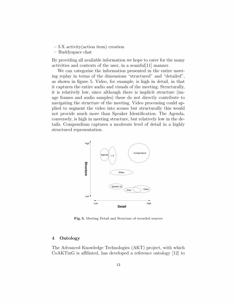
– I-X activity(action item) creation– Buddyspace chat
By providing all available information we hope to cater for the manyactivities and contexts of the user, in a seamful[11] manner.
We can categorise the information presented in the entire meet-ing replay in terms of the dimensions “structured” and “detailed”,as shown in figure 5. Video, for example, is high in detail, in thatit captures the entire audio and visuals of the meeting. Structurally,it is relatively low, since although there is implicit structure (im-age frames and audio samples) these do not directly contribute tonavigating the structure of the meeting. Video processing could ap-plied to segment the video into scenes but structurally this wouldnot provide much more than Speaker Identification. The Agenda,conversely, is high in meeting structure, but relatively low in the de-tails. Compendium captures a moderate level of detail in a highlystructured representation.
Low High
Structure
Low
Detail
Speaker Id
Agenda
Slides
Compendium
VideoChat
I−X
High
Fig. 5. Meeting Detail and Structure of recorded sources
4 Ontology
The Advanced Knowledge Technologies (AKT) project, with whichCoAKTinG is affiliated, has developed a reference ontology [12] to
13

describe the domain of computer science research in the UK, exem-plified by the CS AKTive Space semantic web application. Withinthis domain, its vocabulary is able to express relationships betweenentities such as individuals, projects, activities, locations, documentsand publications. For purposes of capturing meeting specific infor-mation, the reference ontology is already suitable for encapsulating:
– the meeting event itself– meeting attendees– projects which are the subject matter of the meeting– documents associated with the meeting, including multimedia
For activities such as meetings, which we wish to index and navi-gate temporally, the way in which the ontology represents time isof particular relevance. The reference ontology contains the notionof an Event, which is a Temporal-Thing that can define a duration,start and end times, a location and agents involved in the event.More importantly, each Event can express a has-sub-event relation-ship with any number of other Events, and it is with this propertythat we build up our temporal meeting structure. Within the ontol-ogy there are also many Event sub-classes, such as Giving-a-Talk,Sending-an-Email, Book-Publishing, and Meeting-Taking-Place.
While the reference ontology provides a foundation for describingmeeting related resources, the CoAKTinG meeting ontology (figure6) extends the OWL version of AKT reference ontology to betterencompass concepts needed to represent collaborative spaces andactivities, including:
– time properties sufficient for multimedia synchronisation– distributed gatherings to represent meetings which simultane-
ously take place in several spaces, both real and virtual– exhibition of information bearing objects; e.g. showing a slide as
part of a presentation– compound information objects; e.g. to describe a presentation
consisting of several multimedia documents– rendering of information objects; e.g. JPEG image of a slide– transcription of events; e.g. a video recording of a presentation,
minutes of a meeting– annotation of events; e.g. making a verbal comment, creating a
Compendium node
14

Fig. 6. A simplified representation of the meeting ontology
When a meeting takes place we “mark up” the event with meta-data - details such as those listed above - to build a structured de-scription of the activities that occur. Through use of an ontologyshared and understood by several different tools, we can lower theworkload needed to provide usable and useful structure.
5 Case Studies
5.1 e-Response
One CoAKTinG demonstration scenario, termed e-Response, sur-rounds an evolving environmental emergency: an oil spill is threat-ening a sea-bird reserve. The response team (whose members aretogether assumed to have a wide-ranging scientific background) hasto generate a plan for responding to this emergency – the creationof this plan is the synthesis task here.
In constructing their plan, the members of the team follow – indi-vidually and as a group – specific response procedures. While someof these may be extemporised and contingent on circumstances, oth-ers may be instances of ’standard operating procedures’, generic ap-
15

proaches to archetypal activities, which can be downloaded froma central web-store. In addition to the human agents in this envi-ronment, automated agents exist to provide tide data and weatherforecasts, simulate the progress of the oil slick, poll centralised datastores for details of available human expertise in specific fields and soon. The interactions are governed by the activities, issues and con-straints that arise, and mediated by the I-X interfaces of the teammembers, which present to them the current state of the collabora-tion from their individual perspectives, and allow them to decomposeactivities, refine elements of the plan, delegate issues, invoke the au-tomated agents etc, all serving to facilitate the team’s task.
5.2 CombeChem
The CombeChem project aims to enhance structure property corre-lation and prediction by increasing the amount of knowledge aboutmaterials via synthesis and analysis of large compound libraries. Au-tomation of the measurement and analysis is required in order to dothis efficiently and reliably while ensuring that wide disseminationof the information occurs together with all the necessary associatedbackground (raw) data that is needed to specify the provenance ofthe material. The project aims for a complete end-to-end connectionbetween the laboratory bench and the intellectual chemical knowl-edge that is published as a result of the investigation; this necessi-tates that all steps in the process are enhanced by a suitable digitalenvironment. CombeChem has achieved many parts of this ambitiousprogramme, e.g. the smart laboratory (smarttea.org), grid-enabledinstrumentation, data tracking for analysis, methodology for publi-cation@source, process and role based security and high throughputcomputation.
The CoAKTinG tools provide support for the e-Science process inCombeChem and they also enable the digitisation of ’missing links’in the processing chain which form part of the typical collaborativescientific processes that we are attempting to enhance using the gridinfrastructure: support of the experimental process, tracking andawareness of people and machine states, capturing of the discussionsabout data as well as the traditional metadata, and enriched meta-data regarding these components to support interlinking.
The BuddySpace systems can be adapted to show and track theinteractions between the staff and equipment using the National
16
Crystallographic Service (NCS), providing information to their usersabout the state of the service. Compendium provides the harness toensure more adequate capture of the discussions in analysis, whileProcess Panels provide the means to initiate and track key tasksand issues. Additionally the ideas from CoAKTinG provide differ-ent techniques to achieve the necessary multi-user interaction in realtime over the network and give CombeChem the opportunity to im-plement the “video interaction” collaboration part of CombeChemusing event based ontologies to annotate real time streaming mediaand content.
These various components are valuable complements to Combe-Chem individually but jointly are even more powerful. For example,Process Panels can exploit the presence information derived fromBuddySpace with respect to instrument status and operator avail-ability to offer more informed task delegation options. This com-pletes the chain of digital support and capture, maximising the po-tential for re-use of the digital information in support of the scientificprocess.
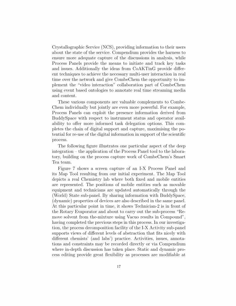
The following figure illustrates one particular aspect of the deepintegration – the application of the Process Panel tool to the labora-tory, building on the process capture work of CombeChem’s SmartTea team.
Figure 7 shows a screen capture of an I-X Process Panel andits Map Tool resulting from our initial experiment. The Map Tooldepicts a real Chemistry lab where both fixed and mobile entitiesare represented. The positions of mobile entities such as movableequipment and technicians are updated automatically through the(World) State sub-panel. By sharing information with BuddySpace,(dynamic) properties of devices are also described in the same panel.At this particular point in time, it shows Technician-2 is in front ofthe Rotary Evaporator and about to carry out the sub-process “Re-move solvent from the-mixture using Vacuo results in Compound”,having completed the previous steps in this process. In our investiga-tion, the process decomposition facility of the I-X Activity sub-panelsupports views of different levels of abstraction that fits nicely withdifferent chemists’ (and labs’) practice. Activities, issues, annota-tions and constraints may be recorded directly or via Compendiumwhere in-depth discussion has taken place. Static and dynamic pro-cess editing provide great flexibility as processes are modifiable at
17

run-time in response to unexpected changes. The ability to store,retrieve and refine process models is important in the Chemistrydomain where existing processes are constantly reviewed and modi-fied to discover or synthesise new chemical compounds. This facilityalone makes I-X a valuable back-end component for integration withthe existing CombeChem Grid.
Fig. 7. I-X Process Panel configured for e-Chemists
6 Conclusions
This paper has introduced the tools that have been developed bythe CoAKTinG project and identified how they are typically used inmeetings, and also shown how they are being explored in scenariossuch as e-Response and CombeChem.
Acknowledgments
This work is funded by the UK Engineering and Physcal SciencesResearch Council under grant number GR/R85143/01, in associa-tion with the Advanced Knowledge Technologies Interdisciplinary
18

Research Collaboration. The AKT IRC research partners and spon-sors are authorized to reproduce and distribute reprints and on-linecopies for their purposes notwithstanding any copyright annotationhereon. The views and conclusions contained herein are those of theauthors and should not be interpreted as necessarily representing theofficial policies or endorsements, either expressed or implied, of otherparties. We are grateful to members of the CombeChem team fortheir assistance with the case study: Jeremy Frey, Gareth Hughes,Hugo Mills, monica schraefel and Graham Smith. CombeChem isalso funded by the EPSRC under grant number GR/R67729/01.
References
1. The CoAKTinG project. http://www.aktors.org/coakting/2. The Access Grid. http://www.accessgrid.org/3. Conklin, J., Selvin, A., Shum, S.B., Sierhuis, M.: Facilitated Hypertext for Col-
lective Sensemaking: 15 Years on from gIBIS. In: Proceedings The Twelfth ACMConference on Hypertext and Hypermedia (Hypertext ’01). (2001) 123–124
4. Selvin, A., Sierhuis, M.: Towards a Framework for Collaborative Modelling andSimulation. In: Workshop on Strategies for Collaborative Modelling and Simu-lation, CSCW’96: ACM Conference on Computer-Supported Cooperative Work,Boston, MA, USA (1996)
5. Conklin, J., Yakemovic, K.C.B.: A Process-Oriented Approach to Design Ratio-nale. Human-Computer Interaction 6 (1991) 357–391
6. Selvin, A.: Supporting Collaborative Analysis and Design with Hypertext Func-tionality. Journal of Digital Information 1 (1999)
7. Shipman, F., McCall, R.: Supporting Knowledge-Base Evolution with IncrementalFormalization. In: Proc. ACM CHI’94: Human Factors in Computing Systems,Boston, Mass., ACM Press: New York (1994) 285–291
8. Selvin, A., Shum, S.B.: Repurposing Requirements: Improving Collaborative Sense-making over the Lifecycle. In: Profess’99: International Conference on ProductFocused Software Process Improvement, Oulu, Finland. (1999) 539–559
9. Tate, A., Dalton, J., J. Stader, J.: I-P2 - Intelligent Process Panels to SupportCoalition Operations. In: Proceedings of the Second International Conferenceon Knowledge Systems for Coalition Operations (KSCO-2002), Toulouse, France(2002)
10. Tate, A.: <I-N-C-A>: an Ontology for Mixed-initiative Synthesis Tasks. In:Proceedings of the Workshop on Mixed-Initiative Intelligent Systems (MIIS) atthe International Joint Conference on Artificial Intelligence (IJCAI-03), Acapulco,Mexico (2003)
11. Chalmers, M., MacColl, I., Bell, M.: Seamful design: Showing the seams in wearablecomputing. In: Proceedings of IEE Eurowearable 2003, Birmingham, UK (2003)11–172
12. The AKT Reference Ontology. http://www.aktors.org/ontology/
19

Distributed Data Management and Integration:The Mobius Project
Shannon Hastings and Stephen Langella, Scott Oster, Joel Saltz
Department of Biomedical InformaticsMultiscale Computing Laboratory
The Ohio State UniversityColumbus, OH, 43210
Abstract. Advances in computational resources, the concept of the Gridand the development of middleware and applications to build and sup-port the Grid will give Grid users the power to access and interpret largeamounts of heterogeneous data. Metadata, data that describes data, canbe used to represent and define the protocols of the Grid, as an abstrac-tion between services and datasets, and to provide syntactic or semanticdescriptions and annotations of any sized datasets so that they may bediscovered, communicated, and analyzed efficiently. In this document, wewill present “Mobius”, which can be described as a generic and extensibleset of protocols and services for managing data in a Grid environment.
1 Introduction
With the emergence of Grid computing and Web services architec-tures, it is increasingly critical to address the information serviceneeds of loosely coupled systems. A multi-institutional Grid envi-ronment will contain many data sources, which maintain differenttypes of data using different storage mechanisms. Management ofdata and metadata is a major task in such systems. Seamless in-tegration of data can facilitate the discovery of data-oriented find-ings that would not be possible without a system that supports thedistributed management of metadata and data in a scalable envi-ronment. A middleware system which provides basic building blockservices for metadata and data management can be extended bymany other service areas such as semantic query services, ad-hocdata warehouse services, and specialized data integration services.
In this paper, we describe the architecture of Mobius, a middle-ware framework designed for efficient management of data and meta-data in dynamic, distributed environments. Its design is motivatedby the Grid [7, 5, 6] (in particular by the activities of the Data Ac-cess and Integration Services group at Global Grid Forum [8, 4, 1, 2]

), by earlier work done at General Electric’s Global Research Cen-ter [13], and by particular domain application area requirements.Biomedical research studies, for example, can involve integration ofdata, including proteomic, molecular, genomic, and image data in amulti-institutional environment. Mobius provides a set of generic ser-vices and protocols to support distributed creation, versioning, andmanagement of data models and data instances, on demand creationof databases, federation of existing databases, and querying of datain a distributed environment. Its services employ XML schemas torepresent metadata definitions (data models) and XML documentsto represent and exchange data instances.
As an example, consider biomedical research studies that collectdata in complex data types, with partial syntactic and semanticoverlap. A researcher can develop a hypothesis and accrue severaltypes of patient and laboratory related data. The researcher needsto create databases to maintain data for patients and laboratory re-sults. Data may have also been previously stored in multiple sourcesand databases, potentially created by other researchers. In whichcase, data must be integrated from these potentially heterogeneoussources for analysis. The researcher should be able to use a system tocreate an ad-hoc data warehouse spanning multiple databases (2Dgel data, clinical data, lab data, drug treatment data, and moleculardata) to enable distributed analysis. The researcher should also beable to use the ad-hoc data warehouse to carry out queries to testhypotheses. Any two databases may define data that contain thesame semantic content with completely different structure represen-tations. The analysis of data may lead to collection of new datasetsas well as new types of data. This type of scenario can be supportedby a system that will allow the researcher to:
– create schemas which describe their data models, register andshare these data models with other collaborators, manage andversion them while new data types are added or deleted,
– facilitate translation between data models that have the samesemantic meaning, but different structure, and
– create, integrate, and manage databases and data that conformto these data models.
Mobius consists of three core service areas: Global Model Ex-change (GME), Data Instance Management (Mako), and Data Trans-
21

lation Service (DTS). These service areas and underlying proto-cols support distributed creation, versioning, management of datamodels defined by XML schema, on-demand creation of distributeddatabases, federation of existing databases, querying of data in a dis-tributed environment, and on demand translation of instance datafrom one data model to another.
Using Mobius, the biomedical researcher can develop databasesand querying capabilities for her studies as follows. The researcherfirst designs XML schemas describing the data types she wants tomaintain. The GME provides several alternatives for the researcherto create and register her schemas: 1) The researcher can search theGME for existing schemas and may use one that suits her researchstudy. 2) She can version an existing schema by adding or deletingdata attributes. 4) The researcher can create a new schema with newattributes and structure. 5) She can compose a schema using newattributes and by referencing multiple existing schema entities in herschema. Once the schema is created, it is registered with the GMEso that other researchers can search for it, and the Mako servicescan use it to create new databases and validate data against its datamodel. The researcher can now instantiate one or more Mako serversto maintain the databases conforming to the schemas. She can alsoregister the schemas with existing running Mako servers. The Makoservers create databases using the XML schemas so that new datacan be entered and maintained across the system. When a new dataset is submitted (as an XML document) to a Mako server, the serveringests the document, stores the data specified in the document inthe databases, and indexes them. Any given data set can also bedistributed across a collection of Mako servers and rematerialized asneeded at query or retrieval time. With the data effectively stored,the researcher can then retrieve data from these databases usingqueries expressed in XPath [3].
2 Requirements
As mentioned earlier, the world is increasingly becoming more de-pendent on electronic data management from patient medical recordsand research data spread across institutions around the world to re-mote monitoring of airline engine sensor data. Data is everywhere,and the easier that it can be integrated and used together the more
22

useful it becomes. This section will enumerate some basic require-ments for managing data in a grid environment and elaborate oneach in a use case driven approach.
2.1 Global Model Management
In order for services on the grid to communicate with each other,their data must be described in a format that is understood by eachinvolved component. Thus a data management system for the gridmust provide a method for defining metadata and data, we will referto this definition as a data model. A data model is the specificationof the structure, format, syntax, and occurrences of data instances.In order for services to communicate with one another they mustagree on a data model over which they communicate. In order forsuch models to exist, they must be globally available to every service,assuming the service has access control rights to obtain and view themodel. Making data models globally available and uniquely identi-fiable forms a conceptual global model consisting of the individualmodels. Therefore, given proper credentials, one model may refer-ence previously defined entities in another model. For example, ifthe entity Patient is defined in the model Hospital, it could be ref-erenced by the model Clinic. This means that the Clinic’s definitionof Patient is equivalent to the Hospital’s definition of Patient. Sinceall entities are globally identifiable, entities within the schema mustbe unique. Therefore once the Patient entity is defined, it cannot bedefined by another model. Although this promotes standardizationof data definitions, this will not be an acceptable solution for thegrid, as there will invariably be competing definitions for these enti-ties. This problem can be solved by namespaces. Entities defined inmodels should be assigned to a namespace, where entities are uniquewithin their namespace. The combination of the entities name andnamespace makes the entity unique within the grid. Thus, entitiescan be referenced, systems and data integration become simpler, andstandards can be promoted.
2.2 Data Instance Management
Services on the grid will need a method for storing and querying dataand metadata. This will be integral for service communication on thegrid. Given valid credentials, data should be able to be stored across
23

a series of heterogeneous loosely-coupled machines. This will allowfor data storage systems to be virtually any size and scale withinthe grid as well as become ad-hoc and dynamic in size and shape.The system should also provide the ability to allow trusted users toupdate, query and delete the data. These generic base storage serviceinterfaces can be extended by application specific grid users in orderto tailor them for specific needs.
2.3 Data Translation
It will often be the case that institutions will have different methodsfor modeling data which may be conceptually or semantically thesame. It would be beneficial to both institutions to be able to trans-late between one another’s data models such that each can leveragethe other services. Where possible, the simplest way to share dataand services is to use common models, but in practice, this is notalways possible. This begs the existence of a registry architecturefor managing and discovering services on the grid that translate be-tween defined data models. Such an architecture would allow servicesto programmatically identify and leverage other computational ser-vices which would otherwise not be possible. This, of course, doesnot mean that the automatic structural or semantic data translationproblem is solved. This simply gives a service architecture wheredata translation services, possibly written by domain experts, arepublished and can be trusted between the two domains in which thedata is translated and potentially accepted by others as the standard.
3 Related Work
Due to the nature of a large componentized middleware architec-ture, covering all possible related work which may be leveraged bythis architecture is beyond the scope of this paper. In this section wewill cover the related work which deals specifically with grid mid-dleware protocols and grid metadata management; the main con-tributing components of the mobius architecture. We will not coverrelated work pertaining to specific service implementation details.However, if there is related work which addresses a similar problem,as a Mobius service implementation, it can simply be wrapped withthe Mobius service protocols or be used in coordination with theMobius middleware.
24

There have been several projects which focus particularly on ser-vice infrastructure for metadata management, and a few which specif-ically target execution on the grid. Storage Resource Broker (SRB) [20]in coordination with the Meta Information Catalogue (MCAT) [15] isa grid-enabled middleware system for accessing heterogeneous datastorage services in a client-server framework. In its current incarna-tion, the SRB system uses the term metadata to mean a predeter-mined set of key-value pairs which describe attributes of the dataset. The user can add extra key-value entities which can be used toquery and discover data sets in the SRB framework. The key definingdifference between the SRB/MCAT solution and the Mobius frame-work is the way in which metadata is handled in the environment.The metadata in SRB is not a user-designed structure which is apublished and managed entity. It is used to describe a specific dataset or data sets and the metadata itself does not contain a partic-ular unique name, or structure (other than key-value). The Mobiusframework enables structured metadata of any size or shape to beuser-defined, published, and managed. It also enables instance dataconforming to this data to be created and validated. Although thetwo systems at a high level seem to support similar interactions,store and retrieve data which can be queried and discovered usingmetadata, they are quite different in scope and direction.
Another grid system for management of metadata is the Meta-data Catalog Service (MCS) [16]. The MCS system was originallycreated to support metadata management in the Grid Physics Net-work (GryPhyN) [10]. MCS is closely related to SRB in that itscurrent use and aim is to store metadata about logical files in a datagrid. Although it does not provide standard data access interfacesthat SRB or Mobius provides, it does store and allow querying ofthese logical files’ metadata. Like MCAT, MCS models metadata asa set key-value pairs and not as a user-defined complex structurewhich can be comprised of other user-defined structures. Mobius ad-dresses the concern that a generic platform for metadata in a gridshould be capable of being structured and comprised of pre-existingstructures from experts of their respective domains.
25

4 Global Model Exchange
The driving force behind the need for a global service architectureto manage user-defined data models can be laid out as a set of use-case driven requirements. A user in the grid would like to be ableto create, publish, and version a data model, possibly defined usingXML Schema. That model may be used by many other services atservice runtime. This feature requires that those requesting servicesbe able to request model definitions by namespace and name, andbe guaranteed that they will receive the same model as any otherservice issuing the same request. The publishing grid user wouldlike other grid services to be able to use that model and detectand use its changes, enabling possible programmatic updating ofrunning services. A particular model may be made up of severalsub-models as defined under different namespaces. The grid userwould like to be assured that when a model is referenced in the grid,there is some assurance it is always available, as well as any of thesub-models that it may be referencing which are defined by othergrid users. A service infrastructure that provides an implementationof these requirements would be the core building block for otherservices as model-to-model translation or mapping services, genericad-hoc model instance storage services, and robust service-to-servicedata communication. These requirements could mostly be met witha combination of current technologies and with a large amount ofnew philosophic agreements with all users. For example, the currentdefacto standard for schema publishing uses web servers, HTTP,and DNS maintained namespaces, and schemas are downloaded viaHTTP requests to a URL matching their fully qualified names. If acertain level of service and availability could be guaranteed, serversmaintained all pervious versions, and authorities were put in placeto allow users to publish schemas to appropriate namespaces, wecould approach a solution to these problems. However, a new set ofgrid services with the sole purpose of providing an implementationof these requirements will be much easier to adopt in practice, andwill be a fundamental building block of many future data driven gridservices.
The Global Model Exchange (GME) is a service that respondsto the requirements stated above. It is responsible for storing andlinking data models as defined inside namespaces in the distributed
26
Root GME
GME GME GME
GME GME GME
Sample Global Model Exchange Grid
org edu
gov
gridforum.org osu.edu nih.gov
GME
cis.osu.edu
GME
medicine.osu.edu
Fig. 1. GME Architecture
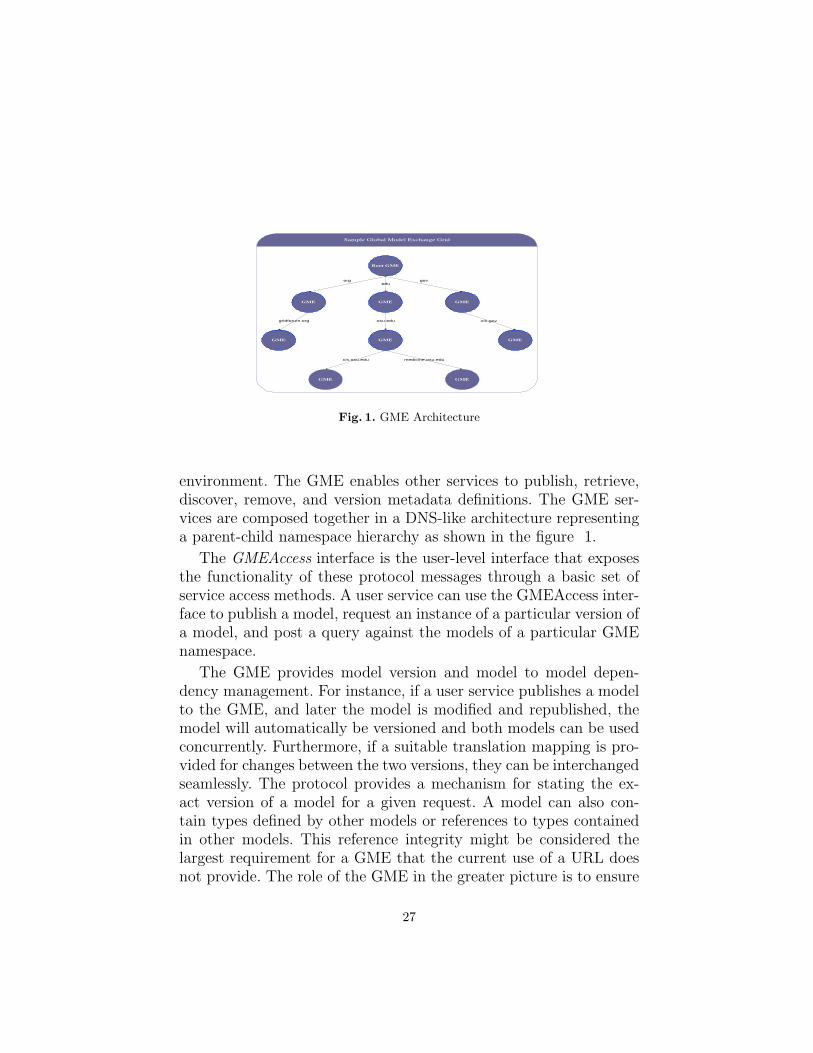
environment. The GME enables other services to publish, retrieve,discover, remove, and version metadata definitions. The GME ser-vices are composed together in a DNS-like architecture representinga parent-child namespace hierarchy as shown in the figure 1.
The GMEAccess interface is the user-level interface that exposesthe functionality of these protocol messages through a basic set ofservice access methods. A user service can use the GMEAccess inter-face to publish a model, request an instance of a particular version ofa model, and post a query against the models of a particular GMEnamespace.
The GME provides model version and model to model depen-dency management. For instance, if a user service publishes a modelto the GME, and later the model is modified and republished, themodel will automatically be versioned and both models can be usedconcurrently. Furthermore, if a suitable translation mapping is pro-vided for changes between the two versions, they can be interchangedseamlessly. The protocol provides a mechanism for stating the ex-act version of a model for a given request. A model can also con-tain types defined by other models or references to types containedin other models. This reference integrity might be considered thelargest requirement for a GME that the current use of a URL doesnot provide. The role of the GME in the greater picture is to ensure
27

distributed model evolution and integrity while providing the abilityfor storage, retrieval, versioning, and discovery of models of all shape,complexity, and interconnectedness in a grid-like environment.
A future extension of the GME service architecture would be tosupport semantic model storage, versioning, and querying. Storingdata models without semantics is a base case building block for be-ing able to begin to store, search, and reason about semantic datamodels. We would like to extend the GME basic service by not onlystoring the model, but also adopting a semantic model definitionlanguage such as RDF [18] and provide higher level querying forthose models. One could imagine being able to pose the question,”Are there any models published anywhere in the grid that havesomething to do with cancer research?”. With higher level semanticmodel storage and querying, questions like this can be applied acrossall data models in all namespaces in the grid.
5 Mako
Mako is a service that exposes data resources as XML data servicesthrough a set of well-defined interfaces based on the Mako protocol.A data resource can be a relational database, an XML database, afile system, or any other data source. Data resources are exposedthrough a set of well-defined interfaces, thus exposing specific dataresource operations as XML operations. For example, once exposed,a relational database would be queried through Mako using XPathas opposed to querying it directly with SQL. Mako provides a stan-dard way of interacting with data resources, thus making it easy forapplications to interact with heterogeneous data resources.
5.1 Mako Interfaces
The Mako client interfaces are similar to those of an XML database,however, since Mako is a distributed service, the interfaces them-selves are motivated by the work of the Data Access and Integration(DAIS) [4, 1, 2] working group in the Global Grid Forum (GGF) [8].Mako defines a set of access interfaces that define the data opera-tions, and it also defines a set of handles that implement said oper-ations on a given context. For example, the XPathAccess interfacewhich defines XPath operations, is implemented by the XMLCol-lectionHandle and by the XMLDocumentHandle. In the context of
28

the XMLCollectionHandle the XPath operations are implementedand applied across the entire collection, whereas in the context ofthe XMLDocumentHandle the XPath operations are performed onlyagainst the XML document that the XMLDocumentHandle repre-sents. In all Mako provides three handle types, a XML Data ServiceHandle, a XML Collection Handle, and a XML Document Handle.
5.2 Mako Architecture
Clients interact with Mako over a network; the Mako architectureillustrated in Figure 2 contains a set of listeners, each using an im-plementation of the Mako communication interface. The Mako com-munication interface allows clients to communicate with a Mako us-ing any communication protocol. For example, if the communicationinterface is implemented using Globus [9] security, clients may com-municate with Mako using the Globus Security Infrastructure (GSI).Each Mako can be configured with a set of listeners, where each lis-tener communicates using a specified communication interface.
Fig. 2. Mako Architecture
When a listener receives a packet, the packet is materialized andpassed to a packet router. The packet router determines the type ofpacket and decides if it has a handler, described below, for processinga packet of that type. If such a handler exists, the packet is passedonto the handler which processes the packet and sends a response tothe client.
29

5.3 Mako Protocol
The Mako Protocol defines a set the packet types that a Mako mayprocess. This section will give an overview of some of the operationsthat the Mako protocol supports.
Service Data Service Data, a term often used by the OGSI [17]working group in the GGF, refers to metadata about a given ser-vice. Mako service data contains information on when the Mako wasstarted, information on the underlying data resource, a list of requesttypes supported, etc.
Collection Management In the context of XML databases, the com-mon nomenclature for referring to a group of related instance docu-ments in a single storage service is a Collection. This is very similar tothe relational database concept of a database. The concept divergesslightly, in that collections can have sub collections, and collectionsmay not have a single schema (or any at all) associated with them.Mako has three request packets for managing collections of XMLdocuments. The CreateCollectionRequest packet is used to createa new XML collection on a Mako. The RemoveCollectionRequestpacket can be used to remove a collection from a Mako. Finally, theCollectionListRequest packet requests a list of collections that existson a Mako or in a sub collections on a Mako.
Schema Management Each collection in Mako can be restricted toonly accept XML documents from a set of certain types. This is ac-complished by specifying a set of XML schemas in which a XMLdocument must be validated against. The Mako protocol provides amethod for adding and removing schemas to and from an XML col-lection within a Mako. The SubmitSchemaRequest packet is used tosubmit schemas to a collection in a Mako, and the RemoveSchemaRe-quest packet removes them. The SchemaListRequest packet can beused to get the list of schemas supported by an XML collection.
Document Management The Mako protocol defines methods for sub-mitting, updating, removing, and retrieving XML documents. TheSubmitXMLRequest packet is used to submit documents to an XMLcollection in a Mako. Upon submission, Mako assigns each entity a
30

unique identifier; later we will see why this identifier is important.XML documents that reside in a Mako can be updated using XUp-date [14], the XUpdateRequest packet is used to accomplish this.
Mako provides two methods of removing documents. First, a listof documents can be removed by specifying their unique identifiers,this is done using the RemoveXMLRequest packet. Second, XMLdocuments can be removed by specifying an element identifyingXPath [3] expression. The XPathRemoveRequest packet is used toremove XML documents that meet an XPath expression.
The RetrieveXMLRequest packet is used to retrieve XML docu-ments, or a subset of XML documents, from a Mako. Documents,or subsets of XML documents, can be retrieved by specifying theirunique identifier. Recall that each element in an XML document isgiven an identifier, making any subset of a document uniquely ad-dressable. The Mako protocol also allows the level of retrieval to bespecified. For example, if you think of an XML document as a tree,then given a unique identifier, one would be able to specify howmany levels of children should be included in the materializationof the document. Elements containing children that are below theheight specified would not be included in the materialization, how-ever references to their immediate children would be included. Thisfeature becomes quite valuable when working with large datasets, inthat full documents do not need to be materialized just to view par-tial results. It also allows one to build a demand driven DocumentObject Model (DOM) on top of the protocol. In general such a fea-ture improves application performance by allowing the applicationto specify how data is materialized.
Querying Mako provides query support through the use of XPath [3],XPath queries are performed using the XPathRequest packet.
5.4 Mako Handlers
As specified in the architecture section, when a Mako receives apacket, the packet is given to the handler that processes that typeof packet. Thus, for each packet type in the Mako protocol, thereis a corresponding handler to process that packet type. In order toabstract the Mako infrastructure from the underlying data resource,there is an abstract handler for each packet type. Thus, for a given
31

data resource, a handler extending the abstract handler would becreated for each supported packet type. This isolates the processinglogic for a given packet, allowing a Mako to expose any data resourceunder the Mako protocol. The initial Mako distribution contains ahandler implementation to expose XML databases that support theXMLDB API [21]. It also contains handler implementations to ex-pose MakoDB. MakoDB is an XML database optimized for interact-ing in the Mako framework. Implementations exposing other dataservices will be distributed as they become available.
5.5 Exposing a Data Service with Mako
Data services can easily be exposed through the Mako protocol bycreating an implementation of the abstract handlers. Since thereis an abstract handler for each packet type in the protocol, dataservices can expose all or a subset of the Mako protocol. Once handlerimplementations exist, Mako can be easily configured to use them.This is done in the Mako configuration file, which contains a sectionfor associating each packet type with a handler.
5.6 Global Addressing
We mentioned earlier that Mako provides a method of uniquely iden-tifying elements contained in XML documents. In actuality theseelements are uniquely identified across the collection in which theyreside. Mako also provides a method of globally addressing XMLelements. This is done using the three tuple id, (Mako URI, collec-tion, elementId). Being able to globally address entities within Makoprovides several advantages. Most importantly it facilitates data fed-eration across multiple Makos.
5.7 Virtual Inclusion
One example of how data may be federated across multiple Makosis by virtual inclusion. Virtual inclusion is a reference within anXML document to another XML document. This means that Makoallows XML documents to be created that may contain references toexisting XML documents or elements, both local and remote. In thisway, an XML document can be distributed and stored across multipleMako servers by storing subsections of the document remotely and
32

integrating them with references. This ability is critical in enablinglarge data documents to be partitioned across a cluster while stillmaintaining the single document semantics of a model.
5.8 VMako
Utilizing Mako’s component architecture, alternate protocol han-dlers can be installed in a Mako server to enable it to utilize re-mote Mako instances. The Virtual Mako, illustrated in Figure 3, isa collection of protocol handler implementations that extend the op-eration of the data services to operate on an administrator-definedset of remote Makos. It maps a number of Virtual Collections to aset of remote collections. This simplifies the client-side complexityof interfacing with multiple Makos by presenting a single virtualizedinterface to a collection of federated Makos.
Fig. 3. Virtual Mako
For example, the SubmitSchemaHandler is extended to broadcastschema submission requests to all remote Makos, and return an ag-gregated response. The SubmitXMLHandler utilizes a configurabledata ingestion algorithm to determine what to do with submittedinstance data. It can be configured to distribute instance data tosupporting Makos via a Round Robin scheduler, or any other de-sired distribution mechanism. Other handlers are implemented in asimilar fashion. The Virtual Mako could also be utilized to decluster
33

large data types. By utilizing virtual inclusion, a submitted XML in-stance document could be broken down into separate sub-documents,and distributed across remote Makos. A new document containingreferences to these sub-documents would then by created and storedin a selected remote Mako. A XMLDocumentHandle to this newdocument would be returned to the client. A request to materializethis document would then completely restore the original document.
While this virtualization eases the burden of interfacing with mul-tiple Makos, the primary purpose for a Virtual Mako is to enabledistributed query execution. In a Virtual Mako, the XPathHandleris implemented such that requests are broken down into sub-queriesand sent to appropriate remote Makos. Responses are then aggre-gated at the Virtual Mako, and returned to the client. In the currentimplementation, the Virtual Mako acts as a simple mediator andaggregator. The architecture was designed such that this could bereplaced by a sophisticated distributed join implementation withoutaffecting any client-side code.
Future work for extending the Virtual Mako concept will focuson adding semantic information about remote data types such thatthe Virtual Mako can make informed decisions about where to storedata, as well as utilizing this information to enable ad hoc queries.For example, with ontological knowledge of remote data types andtheir relationships, a query could be executed by utilizing data trans-formation services and by querying for semantically compatible datatypes instead of strict class equality.
6 Data Translation Service (DTS)
The Data Translation Service (DTS) is responsible for managingthe translation between data types. It accomplishes this task bymaintaining a registry of remote mapping services, which providepairwise translation between namespace elements. As an example,consider the use case where a data type A is required to be trans-lated to datatype B. There are two primary motivators for the DTS.The first driver is the need to maintain the link between data storedagainst a particular version of a schema and future versions, as theschema evolves. As data in Mobius is strongly typed against a par-ticular version of at least one schema, it is important to be able toeasily migrate data adhering to a schema when the schema changes.
34

Given a suitable mapping service from one version to the next, datacould either be migrated to the new schema, or left unchanged butmigrated on-demand when requests for data adhering to the newversion is requested.
A second driver is the need to seamlessly translate data types thatare semantically similar but syntactically different. As the number ofdistributed data sources and data types increase, the need for trans-lation between common data types becomes extremely important.It is unreasonable to assume that in a Grid environment all serviceswill use the same data types for services that are slightly related. It isalso unreasonable to assume that even if the Grid started out usingthe same data types for services, that those data types would notslowly evolve and change over time. Inevitably there are subtle dif-ferences between services that work on related data that necessitatevariations in the data’s representation. Rather than try to imposea universal standard representation for all data types, Mobius takesthe approach of encouraging organizations to represent their data asthey see fit, while still enabling them to inter-operate with similardata types via a DTS published translation service. The hope is thatby easing the data transition between separate schema versions, andeven completely different schemas, the communities will be able toevolve standards organically where standards are appropriate.
While the DTS enables point to point translation of data types,it is expected that mapping services will be provided that map theirdata types to appropriate standards, and from said standards to theirdata types. This will enable a broader range of transitive mappingswithout requiring explicit mappings for every data type.
The basic DTSR (Data Translation Service Registry) is a simpleregistry style service architecture. A DTSR will contain the infor-mation that describes the individual DTSs that are running on thegrid. Any user can build a DTS publishable service as long as theirservice implements the DTS service interface and registers itself witha DTSR who is responsible for one of the namespaces it is mappingto or from.
Once this service infrastructure is put in place you can envisionthe DTS being extended to be able to begin to do semantic transla-tion. A user could begin to pose questions like ”Can anyone map my’car’ to their ’car’?”, where ”car” is some model that has some mean-ing to the user to be the semantic model of a car. This will require
35

an ontology registry which will store semantic information and rela-tionships about registered namespace elements. It is expected thatfor many pairs of data types there will be many possible translationsbetween the two, and a semantic model and query language will berequired for users to specify translation preferences. Research in thisarea is ongoing, but it is our belief that a schema-based structuraltranslation service is a necessary base case required prior to support-ing semantic translation.
7 Applications
Although Mobius is a research effort still under active development,it has been successfully leveraged as a data management middle-ware for several applications. In a collaboration with Rescentris, acompany focusing on information management solutions to enhancelife sciences research and development, Mobius has been utilized toprovide a framework for integrating and aggregating collections ofdisparate medical data sets. This work employed Mobius’s abilityto store, retrieve, and query distributed data sets modeled by XMLschema. By using referenced model elements to describe commonmedical metadata, this application was able to interrogate biologi-cally relevant portions of distinct medical data sets. Specifically, aVirtual Mako was used to query and aggregate distributed data setsrepresenting single nucleotide polymorphisms, and molecular cyto-genetic data, via XPath queries.
Mobius has also been leveraged in several applications which oper-ate on large medical image data sets. The Distributed Image ArchiveSystem (DPACS), was designed to support generic image archivaland management in a grid wide environment, and relied heavily onthe Mobius framework’s ability to perform on demand data loadingusing remote element referencing(Virtual Inclusion). The DPACSsystem consists of a front end client application and a collection offederated back end Mako servers. The Mako servers provide the im-age and metadata storage and retrieval, and the client applicationcan be used by user to upload, query, and inspect the archived data.The DPACS client broadcasts data reference queries to the remoteMakos and is able to quickly display the resultant data sets. The re-quested aspects of the data sets are then loaded on demand as neededby the client, such as the metadata, volumetric thumbnails, and ul-
36

timately the image data itself. In another work, Mobius was used tostore and manage image processing workflows and image data sets ina system to support rapid implementation and distributed executionof image analysis applications [11], implemented using the InsightSegmentation and Registration Toolkit (ITK) [12] and VisualizationToolkit (VTK) [19]. In this work the processing pipeline discoveredwork by querying Makos, and processing components utilized Makosto retrieve and store their input and output data sets.
BlockMan, an application which is under current development,supports the distribution and indexing of extremely large data setswhich may not fit within a single nodes storage limit. The BlockManwill ingest large binary data sets, partition and distribute the chunksbased on a user specified model and distribution algorithm. It thenprovidesa query interface into data and parallel retrieval of queriedresults. The uniqueness of this system is its ability of the user to addqueryable meaning to the data set by allowing rich structured user-defined metadata to be attached to the data chunks. This enablesthe users to interactively query into datasets which before were notonly hard to manage physically but extremely hard to locate andinterrogate.
8 Conclusion
As the development of the concept of the Grid continues to evolve,we feel protocols and services for managing metadata, data descrip-tions, and datasets will play a critical role in the ultimate realizationof the Grid. In this paper we have introduced the three core servicesof Mobius: Global Model Exchange (GME), Data Instance Manage-ment (Mako), and Data Translation Service (DTS), and shown howthey can be leveraged both as a data integration framework in insti-tional research studies, and as key components of a global Grid.
References
1. M. Antonioletti, M. Atkinson, S. Malaika, S. Laws, NW Paton, D. Pearson, andG. Riccardi. Grid Data Service Specification. Technical report, Global Grid Forum,2003.
2. M. Antonioletti, A. Krause, S. Hastings, S. Langella, S. Malaika, J. Magowan,S. Laws, and NW Paton. Grid Data Service Specification: The XML Realisation.Technical report, Global Grid Forum, 2003.
37

3. Anders Berglund, Scott Boag (XSL WG), Don Chamberlin, Mary F. Fernandez,Michael Kay, Jonathan Robie, and Jerome Simeon. XML Path Language (XPath).World Wide Web Consortium (W3C), 1st edition, August 2003.
4. Data Access and Integration Services. https://forge.gridforum.org/projects/dais-wg.
5. I. Foster, C. Kesselman, J.M. Nick, and S. Tuecke. Grid Services for DistributedSystem Integration. IEEE, 35(6):37–46, 2002.
6. I. Foster, C. Kesselman, J.M. Nick, and S. Tuecke. The Physiology of theGrid: An Open Grid Services Architecture for Distributed Systems Integration.http://www.globus.org/ogsa, 2002.
7. I. Foster, C. Kesselman, and S. Tuecke. The Anatomy of the Grid: EnablingScalable Virtual Organizations. 15(3), 2001.
8. Global Grid Forum. http://www.gridforum.org/.9. The Globus Project. http://www.globus.org.
10. Grid Physics Network (GryPhyN). http://www.griphyn.org/index.php.11. Shannon Hastings, Tahsin Kurc, Steve Langella, Umit Catalyurek, Tony Pan, and
Joel Saltz. Image processing for the grid: A toolkit for building grid-enabled imageprocessing applications. In CCGrid: IEEE International Symposium on ClusterComputing and the Grid. IEEE Press, May 2003.
12. National Library of Medicine. Insight Segmentation and Registration Toolkit(ITK). http://www.itk.org/.
13. S. Langella. Intellegent data management system. Master’s thesis, ComputerScience Department, Rensselear Polytechnic Institute, 2002.
14. Andreas Laux and Lars Martin. XUpdate Working Draft. Technical report,http://www.xmldb.org, 2000.
15. Meta Information Catalog (MCAT). http://www.npaci.edu/DICE/SRB/mcat.html.16. Metadata Catalog Service (MCS). http://www.isi.edu/ deelman/MCS/.17. Open Grid Services Infrastructure. https://forge.gridforum.org/projects/ogsi-wg.18. Resource Description Framework (RDF). http://www.w3.org/RDF/.19. Will Schroeder, Ken Martin, and Bill Lorensen. The Visualization Toolkit: An
Object-Oriented Approach To 3D Graphics. Prentice Hall, 2nd edition, 1997.20. SRB: The Storage Resource Broker. http://www.npaci.edu/DICE/SRB/index.html.21. XML:DB Initiative for XML Databases. http://www.xmldb.org/.
38

Interoperability and Transformability throughSemantic Annotation of a Job Description
Language
Jeffrey Hau, William Lee, and Steven Newhouse
180 Queens Gate, Department of Computing, Imperial College London,London SW7 2BZ, UK
{jh398,wwhl,sjn5}@doc.ic.ac.uk
Abstract. The ability to submit jobs to foreign computational resourcesis a core requirement in all compute grids. Existing distributed resourcemanagement systems and job submission gateways require jobs to bedescribed in propreitary languages that render transparent submissiondifficult. Standardisation effort to create a common language might re-solve this problem. However, reliance on natural language documentationand the lack of a formal model to describe job attributes makes trans-formation error-prone and open to ambiguity. In this paper, we presentthe use of a generic transformation framework applicable to schema-tised language annotated with ontological metadata to job descriptiondocuments. The paper demonstrates a meta job submission service util-ising the framework to dynamically integrate and select heterogeneousresource management systems by transforming input job descriptions.
1 Introduction
Job Submission Service is one of the most important building blockin a Service-Oriented Architecture based compute grid. There aremany heterogeneous distributed resource management systems (DRM)providing propreitary interfaces to computational resources. Accessto these systems can be characterised by the communication layer,notably command-line interface, socket-based approach, API withdifferent language-bindings[8][9], HTTP web access and the recentadoption of Web Services. Apart from the means of communication,varieties of job description languages have been devised to describethe parameters of the job, such as input, output, arguments, systemrequirements, etc..
Although architectural differences between stakeholders can beaccommodated by providing connectors or API to hide the com-munication detail, the diversity of job description however presents

difficulty for clients to transparently access any computational re-sources without specific knowledge of the description syntax and se-mantics. It induces lock-in, hindering the network effect of Grid-widejob submission.
Recent effort of the Job Submission Description Language work-ing group[7] in the Global Grid Forum aims to solve this problem bystandardisation. The JSDL language presents a common extensiblejob description template absorbing many features accumulated fromexisting languages. The current form of the language centered aroundthe notion of job attributes apparent in many languages (e.g. Clas-sAd[11], Globus RSL[10]). The standardisation effort aims to docu-ment a set of attributes and their meaning to achieve a common un-derstanding across systems, therefore DRM vendors or third-partiescan device transformations to their proprietary language withoutre-architecting their systems.
This paper motivates the use of ontology to compliment the de-scriptive nature of job submission language. Inferences on the rela-tionship of attributes defined in heterogeneous job descriptions canprovide insights to perform automatic transformation in some cases,or aid manual engineering in the under-specified ones. We arguethat the current standard expressed in natural languages can beaugmented with a formal model. We will provide an overview ofa generic transformation architecture prototyped in ICENI[12]. Thearchitecture exploits ontological metadata expressed in the Web On-tology Language (OWL)[3] attached to XSD schemas, in order todynamically transform semantically compatible schematised XML.We will demonstrate how the transformation architecture is instan-tiated inside a meta job submission service to integrate and select atruntime a variety of compatible DRMs automatically. The exemplaralso motivates application of this technique to other Grid services ina generic fashion.
2 ICENI Semantic Transformation Framework
The Semantic Transformation Service is a core element in ICENIto facilitate message exchanges between syntactically and architec-turally incompatible services based on semantic and syntactic trans-formation augmented with architecture connectors. The transforma-tion service extracts message semantics from ontology documents
40
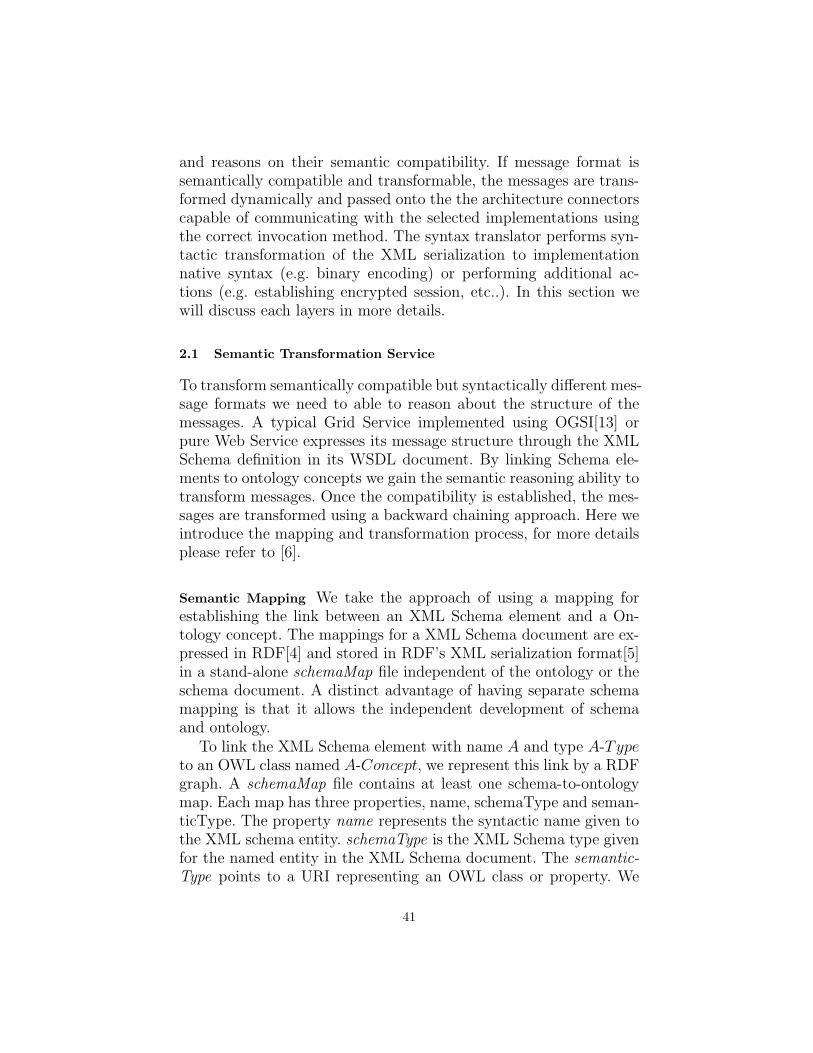
and reasons on their semantic compatibility. If message format issemantically compatible and transformable, the messages are trans-formed dynamically and passed onto the the architecture connectorscapable of communicating with the selected implementations usingthe correct invocation method. The syntax translator performs syn-tactic transformation of the XML serialization to implementationnative syntax (e.g. binary encoding) or performing additional ac-tions (e.g. establishing encrypted session, etc..). In this section wewill discuss each layers in more details.
2.1 Semantic Transformation Service
To transform semantically compatible but syntactically different mes-sage formats we need to able to reason about the structure of themessages. A typical Grid Service implemented using OGSI[13] orpure Web Service expresses its message structure through the XMLSchema definition in its WSDL document. By linking Schema ele-ments to ontology concepts we gain the semantic reasoning ability totransform messages. Once the compatibility is established, the mes-sages are transformed using a backward chaining approach. Here weintroduce the mapping and transformation process, for more detailsplease refer to [6].
Semantic Mapping We take the approach of using a mapping forestablishing the link between an XML Schema element and a On-tology concept. The mappings for a XML Schema document are ex-pressed in RDF[4] and stored in RDF’s XML serialization format[5]in a stand-alone schemaMap file independent of the ontology or theschema document. A distinct advantage of having separate schemamapping is that it allows the independent development of schemaand ontology.
To link the XML Schema element with name A and type A-Typeto an OWL class named A-Concept, we represent this link by a RDFgraph. A schemaMap file contains at least one schema-to-ontologymap. Each map has three properties, name, schemaType and seman-ticType. The property name represents the syntactic name given tothe XML schema entity. schemaType is the XML Schema type givenfor the named entity in the XML Schema document. The semantic-Type points to a URI representing an OWL class or property. We
41

envision graphical tools to help users in creating the schema mapfiles. XML Schema and OWL documents can both be presented ingraphical (trees and graphs) representations, this will allow users todrag and drop entities from both documents to establish the linksbetween them.
Transformation After the semantic compatibility is deduced, we usean algorithm to create the transformation mapping functions[6] be-tween between schema elements of source and target service. A skele-ton1 document is generated from the target service’s schema. Apply-ing the transformation mapping function, a pointer is placed in eachof the value node that refers to the value in the source XML thatneeds to be transformed. Once this transformation document is gen-erated, values are dynamically copied across during transformation.
2.2 Architecture Connector
The architecture connector acts as the bridge between different ser-vice layers. It is at the end of the transformation pipeline that takesmessages off the request queue and invoke the backend service us-ing secured socket, command-line integration with legacy systems orother pluggable means. Apart from being a mere message passingmechanism, it can also acts upon the message to perform actions,such as establishing session, file staging and other routines specificto the application using this framework.
3 A Generic Job Submission Service
The transformation framework (see Figure 1) is instantiated in thegeneric job submission service as the adaptation layer between theWeb Service interface and the underlying distributed resource man-agement systems. The Web Service interface provides a consistentarchitecture to submission clients advocated by the Grid commu-nity. It currently provides submission and monitoring capabilities. Itencapsulates an extensible framework for plugging in architecturalconnectors to communicate with a variety of DRM systems. Theconnectors are associated with a set of XSD schemas describing theXML serialization of the DRM job description syntax annotated with
1 A skeleton is an empty xml document conforming to the XML Schema definition
42

semantic link to a novel job terms ontology extracted from the JSDLlanguage. By accepting input job description in a JSDL-like languagealso annotated with semantic link to the ontology, the transforma-tion framework can deduce whether the input job description aretransformable to any of the underlying DRM target language.
The technique has the advantage that new terms can be addedat will without rewriting the generic job submission service. Onlythe ontological link needs to be appended or modified, which ismore intuitive then a hard-wired transformation using XSLT or otherdeclarative transformation language. Moreover, the semantic modelapplied to the job description can be used to deduce job descriptionsubsumption for scheduling (e.g. different scheduling policies applyto different “classes” of jobs) or monitoring purposes.
Fig. 1. Semantic Transfromation Architecture employed in the meta Job SubmissionService
43

4 Future Work
The syntax translator needs a set of transformation rules to be pre-defined in order to perform the transformation from XML to imple-mentation native syntax. This functionality is necessary due to thelimitation that the transformation service can only automaticallydeduce and perform XML to XML transformation. We are currentlyinvestigating the process of XML to native syntax transformation.This could potentially further simplify our framework by render thesyntax translator redundant.
The transformation framework is developed specifically to solvethe problem of autonomously integrating heterogeneous job submis-sion architectures with the Web Service interface. We believe theframework can be generalised to benefit a broader range of Grid Ser-vices (OGSA), such as resource usage service with diverse account-ing attributes. Applying the current framework to different types ofGrid Services as use cases, we hope to create a generic Grid Servicetransformation framework.
5 Conclusion
In this paper we discussed the difficulty of integrating different jobsubmission languages and the advantages of using semantic meta-data. We proposed a way of binding the metadata to the languageschema by using an ontology. A framework is developed to utilisethe ontologically annotated job description documents. These doc-uments are then transformed dynamically to integrate and selectheterogeneous resource management systems.
References
1. Foster I., Gannon D., Kishimoto H.: The Open Grid Service Architecture (Draft0.14). https://forge.gridforum.org/projects/ogsa-wg March 2004
2. Christensen E., Curbera F., Meredith G., Weerawarana S., Web Service DescriptionLanguage (WSDL), http://www.w3.org/TR/wsdl
3. Bechhofer S., van Harmelen, F., Hendler J., et al: OWL Web Ontology Lan-guage Reference. http://www.w3.org/TR/2004/REC-owl-ref-20040210 (10 Febru-ary 2004)
4. Klyne G., Carroll J. J.: Resource Description Framework (RDF): Concepts andAbstract Syntax (W3C Recommendation). http://www.w3.org/TR/rdf-concepts/10 February 2004
44

5. Beckett D.: RDF/XMLSyntax Sepcification (Revised, W3C Recommendation).http://www.w3.org/TR/rdf-syntax-grammar/ 10 February 2004
6. Hau J., Lee W., Newhouse S.: Web Service Interoperability by Semantic Transfor-mation. Submitted to 3rd International Semantic Web Conference
7. Job Submission Description Language Working Group (JSDL-WG):http://www.epcc.ed.ac.uk/ ali/WORK/GGF/JSDL-WG/
8. Distributed Resource Management Application API Working Group (DRMAA-WG): http://www.drmaa.org
9. Globus Commodity Grid Toolkits: http://www.globus.org/cog10. The Globus Project: http://www.globus.org11. Rajesh Raman, Miron Livny, and Marvin Solomon: Matchmaking: Distributed
Resource Management for High Throughput Computing, Proceedings of the SeventhIEEE International Symposium on High Performance Distributed Computing, July28-31, 1998, Chicago, IL
12. Imperial College e-Science Networked Infrastructure (ICENI):http://www.lesc.ic.ac.uk/iceni/
13. Tuecke S., Czajkowski K., Foster I., Frey J., Graham S., Kesselman C., SnellingD., Vanderbilt P.: Open Grid Service Infrastructure (OGSI) Specification Version1.0
45

Using the Semantic Grid to Build Bridgesbetween Museums and Indigenous Communities
Jane Hunter1, Ronald Schroeter1, Bevan Koopman1, and MichaelHenderson1
DSTC, University of Queensland, Brisbane, Australia 4072{jane, ronalds, bevank, mjh}@dstc.edu.au
Abstract. In this paper we describe a Semantic Grid application de-signed to enable museums and indigenous communities in distributed lo-cations, to collaboratively discuss, describe and annotate digital objectsand documents in museums that originally belonged to or are of culturalor historical significance to indigenous groups. By extending and refiningan existing application, Vannotea, we enable users on access grid nodesto collaboratively attach descriptive, rights and tribal care metadata andannotations to digital images, video or 3D representations. The aim isto deploy the software within museums to enable the traditional ownersto describe and contextualize museum content in their own words andfrom their own perspectives. This sharing and exchange of knowledgewill hopefully revitalize cultures eroded through colonization and glob-alization and repair and strengthen relationships between museums andindigenous communities.
1 Introduction
Many museums, archives, libraries and cultural institutions through-out the world hold large collections of objects that are of cultural orhistorical significance to indigenous communities. Because many ofthese objects were collected without the consent of the traditionalowners, the custodial organizations are now facing the challenges ofdetermining ownership, seeking direction from the traditional own-ers on the future of such objects and repatriating them, storing themor exhibiting them appropriately as requested. This process is mademore difficult because colonization has caused many indigenous com-munities to become dispossessed of their lands and widely dispersedgeographically. New collaborative interactive software tools, high-speed networks and emerging Grid technologies that facilitate com-munication and the sharing of resources and knowledge between ge-ographically dispersed groups, appear to offer an infrastructure that

is ideally suited to the implementation of such digital and physicalrepatriation programs.
Within this paper we describe the software that we are devel-oping specifically for such an application, within the Smithsonian’sNational Museum of the American Indian (NMAI). In the UnitedStates, the Native American Graves Protection and Repatriation Act(NAGPRA) specifies the types of objects and sites to be protectedand/or repatriated. Going beyond the requirements of NAGPRA,the NMAI has established a Culturally Sensitive Collections CareProgram to respond to areas of concern of Native peoples with re-gard to the maintenance, presentation, and disposition of sensitivematerials and information in the collections of the museum. Pastexperience has indicated that many tribal communities want accessto the records of all objects in museum collections associated withtheir community and that after reviewing these, some will be sat-isfied with digital surrogates and access to physical objects whenrequested. The objective of the application described here is to pro-vide the cyber-infrastructure to support such a program.
Within the FilmEd project [1], we developed the Vannotea sys-tem to collaboratively index, annotate and discuss digital film andvideo (MPEG-2) over high bandwidth networks. Vannotea has beenextended to support the sharing, indexing and annotation of high-quality images (JPEG2000) and 3D objects (Direct 3D). Within theIndigenous Knowledge Management (IKM) project [2], we developedsoftware tools to enable non-collaborative indexing, annotation andrights management of indigenous collections. In this paper we ex-plain how we have amalgamated software developed within thesetwo projects to produce a system that enables collaborative index-ing, discussion, annotation and rights management of indigenous col-lections via access grid nodes. We have done this by extending theVannotea software through the addition of:
– Fine-grained rights management components specifically requiredfor Indigenous Knowledge;
– Support for the sharing, indexing and annotation of 3D digitalobjects.
The remainder of this paper is structured as follows. The next sec-tion describes related work and the background and objectives tothe work described here. Section 3 describes the architectural de-sign of the system and the motivation for design decisions that were
47

made. Section 4 describes the issues involved in integrating Indige-nous knowledge management requirements and adding support for3D objects, respectively. Section 5 provides the conclusion and de-scribes plans for future work.
2 Related Work and Objectives
Developing a system to collaboratively index, annotate and discusshigh quality images, videos and 3-D objects within the context ofindigenous collections involves research across a range of disciplines:
– Multimedia indexing, search and retrieval;– Annotation tools for digital multimedia documents;– Collaborative application sharing and document sharing tools;– Authentication, authorization and digital rights management for
Indigenous collections.
In the next four sub-sections we describe relevant, related work inthese areas.
2.1 Multimedia Indexing, Search and Retrieval
There has been considerable work on the indexing, searching andretrieval of images and video content. Many automatic tools havebeen developed to extract low level features [3-6] and various sophis-ticated content-based retrieval methods have been developed (e.g.Query-by-Example, Sketching interfaces, etc.) [7-9]. A number oftools have also been developed to enable semantic descriptions tobe manually attached to video [10-13] and image [14, 15] contentusing free text, controlled vocabularies or ontologies. Other researchgroups are attempting to ”bridge the semantic gap” [3, 16, 17] by au-tomatically generating semantic descriptions using machine-learningtechniques.
Although the majority of multimedia indexing, search and re-trieval systems target images and video, Rowe et. al [18] recentlycreated a tool to capture, model, analyze, and query complex 3Ddata within an archeological museum context. Their focus was onfeature extraction of 3D objects rather than on user annotationsand only asynchronous, non- collaborative user access is provided.
48

None of the work carried out to date allows distributed groups toindex and define the access rights policies associated with multime-dia (images, video and 3D) objects collaboratively. Decision makingwithin many indigenous groups is a group process, carried out by acouncil of elders. When describing cultural or historical objects anddefining access rights, it’s important that geographically dispersedcommunity leaders can do this in collaboration with museum staffthrough real-time group discussions that will generate a legitimateconsensus for future generations.
2.2 Annotating Digital Multimedia Documents
Existing annotation tools (which enable users to attach personalnotes, questions, explanations, etc. to documents) can be categorizedaccording to the media types which can be annotated (text, webpages, images, audio or video, 3D) and the extent of collaborationsupported. This matrix in Table 1, gives an overview of the differentproducts, tools, systems and projects according to these categories.
Non-Collaborative Collaborativeprivate annotations shared annotations logged, live discussions
(assynchronous) (synchronous)Text or text processors like MS Annotea [19], Churchill et al. [21],webpages Word, Adobe Acrobat, etc. Cadiz et al. [20] Collaborative
Information Browser [22]Image Adobe PhotoShop, PAIS [23], Photo Annotator mimio classroom [25]
QTVR (Annotea + SVG) [24]Audio/Video MRAS [26] DTVI [27]3D Jung et al. [28]
Table 1. Annotation Tools
Microsoft’s Distributed Tutored Video Instruction (DTVI) [27] isthe only system that enables students to replay and discuss videosof lectures collaboratively. However it does not support real-timesynchronous annotations. It is based on a combination of WindowsMedia Player and Microsoft’s NetMeeting [29], which uses the T.120protocol [30] for application sharing.
The approach adopted by application sharing protocols such asT.120 (NetMeeting) or VNC-Protocol [31] makes them unsuitablefor our application. In such protocols, the shared application runson a master client or server, which receives the keyboard and mouse
49

events from the participants and sends captured screen/window up-dates back to the participants. Although this framework could po-tentially be used to transfer high frame rates of MPEG-2 video -with sufficient bandwidth and computing power - it clearly tradesefficiency for generality.The protocols are also restrictive in termsof the collaborative environment, e.g. multiple users with multiplesimultaneous cursors are not supported. Therefore we have had tobuild a collaborative environment from scratch, using .NET Remot-ing. This is described in detail in Section 4.4.
2.3 Indigenous Rights Management
One of the challenges that museums face when managing Indigenouscollections is providing support for traditional laws related to theprotection and preservation of sacred or secret resources. Attributesincluding a user’s gender, tribal affiliation and status within the tribeare examples of the fine-grained access control required by organisa-tions such as the National Museum for the American Indian (NMAI).Physical artefacts (such as those stored at the NMAI) also have spe-cial storage, orientation or preservation needs - known as tribal careconstraints. Within the Indigenous Knowledge Management (IKM)project [2, 32] tools have been developed to enable traditional own-ers to define the specific rights requirements associated with digitalobjects and to match them against user profiles to control access. Anumber of other projects [33-35] have been developing software tosupport the management of indigenous multimedia collections butnone provide the same level of granularity, flexibility, scalability andinteroperability or are designed for real-time collaborative use.
Figure 1 shows the rights definition interface which is generatedfrom backend XML Schema files which define the metadata schemes.A graphical user interface is also provided so users can customizethe schema files to suit their particular community’s descriptive andrights metadata requirements. A keyword web-based search interfaceis also provided so users may search, browse and retrieve resourcesthat they are permitted to access. Our objective is to incorporatethe fine-grained rights management components of the IKM soft-ware within the metadata schemas and search interface of the Van-notea system, essentially to enable the IKM software to be used bydistributed groups of users, collaborating in real-time.
50

Fig. 1. Rights definitions using Indigenous Knowledge Management Software
3 System Architecture and Components
Figure 2 illustrates a hypothetical usage scenario of the Vannoteasystem - a live discussion between museum curators and traditionalowners, communicating with each other using Access Grid Nodesand the Vannotea system over the GrangeNet broadband network.
The architecture also reflects the assumption of two separatemetadata stores:
– One (or more) databases for the search and retrieval of multime-dia content based on objective metadata about the multimediacontent. These databases are typically maintained by the custo-dial organization (museum or archive) or owner of the content.
– A separate metadata store that logs the shared personal annota-tions.
Figure 2 also illustrates the four major components of the systemwhich are described in more detail below: User Interface; Indexing,Search and Retrieval; Annotation and Discussion Server; Collabora-tive Environment.
3.1 User Interface
Figure 3 shows the three different components of the user interface.The Content Description component enables the objective and au-
51

Fig. 2. System Architecture
thorized segmentation and indexing of the content, as well as search,browsing and retrieval.
In order to streamline the indexing and segmentation process ofvideo content the Mediaware SDK [36] is used to perform automaticshot- detection. The resulting shot-list is used for further hierar-chical segmentation of shots to frames or aggregation of shots tohigher-level segments (scenes). This hierarchical temporal structur-ing enables easy navigation and browsing through the video. Theentire multimedia object, selected segments, or individual frames,can be described either by entering free text values or using con-trolled vocabulary/terms available through pull-down menus.
Different Content Viewers/Players were required to support thedifferent high quality media formats: MPEG-2 for videos, JPEG2000for images and Direct3D for mesh files. Microsoft Direct3D was cho-sen for its generic mesh file format and native C# API. Direct3Dmesh files describe the model as a series of interconnected polygons.Utilities such as AccuTrans 3D [37] can convert a variety of popular3D languages, including VRML, into this format.
52

Fig. 3. The three key components of the UI
The controls of each Content Viewer/Player vary depending onthe format of the currently shared object. The Video Player featurescommon video playback functionalities (play, pause, seek, stop). TheImage Viewer provides tools such as panning, zooming and tiltingand the 3D Object Viewer (Figure 4) provides controls to zoom, panand rotate or change the current view.
Fig. 4. 3D Object Viewer
Users can attach annotations to selected regions within images,selected segments, frames or frame regions within videos, or areaswithin 3D objects. For 2D this is done through drawing simple shapes
53
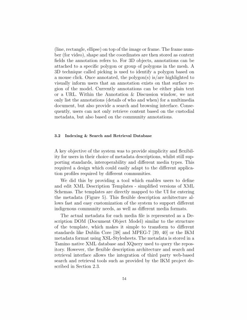
(line, rectangle, ellipse) on top of the image or frame. The frame num-ber (for video), shape and the coordinates are then stored as contextfields the annotation refers to. For 3D objects, annotations can beattached to a specific polygon or group of polygons in the mesh. A3D technique called picking is used to identify a polygon based ona mouse click. Once annotated, the polygon(s) is/are highlighted tovisually inform users that an annotation exists on that surface re-gion of the model. Currently annotations can be either plain textor a URL. Within the Annotation & Discussion window, we notonly list the annotations (details of who and when) for a multimediadocument, but also provide a search and browsing interface. Conse-quently, users can not only retrieve content based on the custodialmetadata, but also based on the community annotations.
3.2 Indexing & Search and Retrieval Database
A key objective of the system was to provide simplicity and flexibil-ity for users in their choice of metadata descriptions, whilst still sup-porting standards, interoperability and different media types. Thisrequired a design which could easily adapt to the different applica-tion profiles required by different communities.
We did this by providing a tool which enables users to defineand edit XML Description Templates - simplified versions of XMLSchemas. The templates are directly mapped to the UI for enteringthe metadata (Figure 5). This flexible description architecture al-lows fast and easy customization of the system to support differentindigenous community needs, as well as different media formats.
The actual metadata for each media file is represented as a De-scription DOM (Document Object Model) similar to the structureof the template, which makes it simple to transform to differentstandards like Dublin Core [38] and MPEG-7 [39, 40] or the IKMmetadata format using XSL-Stylesheets. The metadata is stored in aTamino native XML database and XQuery used to query the repos-itory. However, the flexible description architecture and search andretrieval interface allows the integration of third party web-basedsearch and retrieval tools such as provided by the IKM project de-scribed in Section 2.3.
54
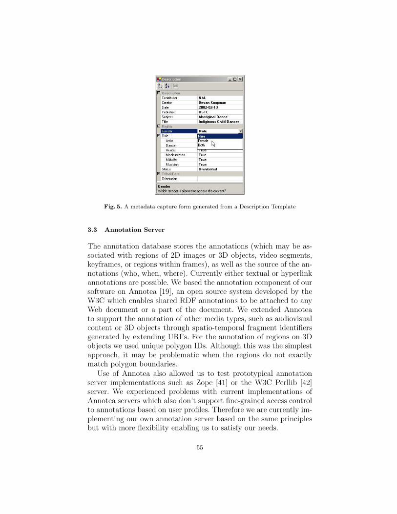
Fig. 5. A metadata capture form generated from a Description Template
3.3 Annotation Server
The annotation database stores the annotations (which may be as-sociated with regions of 2D images or 3D objects, video segments,keyframes, or regions within frames), as well as the source of the an-notations (who, when, where). Currently either textual or hyperlinkannotations are possible. We based the annotation component of oursoftware on Annotea [19], an open source system developed by theW3C which enables shared RDF annotations to be attached to anyWeb document or a part of the document. We extended Annoteato support the annotation of other media types, such as audiovisualcontent or 3D objects through spatio-temporal fragment identifiersgenerated by extending URI’s. For the annotation of regions on 3Dobjects we used unique polygon IDs. Although this was the simplestapproach, it may be problematic when the regions do not exactlymatch polygon boundaries.
Use of Annotea also allowed us to test prototypical annotationserver implementations such as Zope [41] or the W3C Perllib [42]server. We experienced problems with current implementations ofAnnotea servers which also don’t support fine-grained access controlto annotations based on user profiles. Therefore we are currently im-plementing our own annotation server based on the same principlesbut with more flexibility enabling us to satisfy our needs.
55

The flexible architecture of Annotea will also allow us to easilyattach and store audiovisual annotations - small audio or video clipscaptured during the video conferencing discussion. However the cur-rent access grid node videoconferencing tools (vic and rat) preventeasy capture and synchronization of audio and video streams. Re-searchers from the ANU’s Internet Futures Program are currentlyworking on alternative videoconferencing tools [43] which will sup-port easy capture of audiovisual streams from AGN sessions.
3.4 Collaborative Environment
Because Vannotea is implemented in C# within the .NET develop-ment framework, the most flexible, modular and integrated approachto application sharing was to develop it using .NET Remoting. .NETRemoting provides a framework that allows objects to interact witheach other across application domains or on different servers throughevents. Figure 6 illustrates the event-handling architecture of ourapplication. In this example, the client-master is in control of theapplication, the remote clients are joining the session by connectingto the same server-application.
Fig. 6. Event handling using .NET Remoting
The Mediator objects handle the communication between theclients and the server. They can call methods on the remote ob-ject (Coordinator). In return, the Coordinator can call methods onthe Mediator by raising events that the Mediator has subscribed andlistens to. To achieve a form of collaboration, selected events are sim-ulated on all clients. Even mouse movement events can be handled
56

in this way, resulting in several colour-coded mouse pointers withinone application that can all be in control simultaneously.
The MPEG-2 videos are streamed using multicast over VideoLan[44]. VideoLan is controlled by the application server to ensure allclients are watching precisely the same content at the same time.Collaborative viewing of 3D objects can be implemented by:
– Either transferring the whole file and rendering it at the client.This is easier to implement; thin server; each client can have adifferent view. The major disadvantage is that computationallyexpensive rendering must be performed by each client.
– Or rendering it on the server and streaming the rendered resultto each client. This is more efficient because rendering of complex3D objects is computationally expensive. But it is more difficultto implement and to ensure that each client sees the same view.
One objective of the project is to evaluate users’ behavior andobtain user feedback on the different levels of collaboration avail-able during the image / video / 3D object analysis and discussionand annotation processes. We may want to restrict access to sharedapplication controls based on user profiles. Access management ofcontent during collaborative sessions also presents a difficult prob-lem. Participants may have different access rights to content, thatwill be shared during a collaborative session. If a user chooses toopen a new multimedia object, the access rights of each user mustbe compared with the access rights of the object. If one or moreparticipants are not allowed to see the object, the initiating partic-ipant is warned and must choose if the object should be opened orif restricted participants should be excluded from the collaborativesession.
4 Future Work and Conclusions
In this paper we have described a system which combines high-speed networks, access grid nodes and collaborative document- andapplication- sharing software to facilitate the communication andexchange of knowledge between dispersed indigenous communitiesand museum staff. The aim is to deploy and test the software in col-laborative projects between museums, archives and indigenous com-munities, to facilitate cultural repatriation programs. We are cur-rently discussing a collaborative project between the Smithsonian
57
National Museum of the American Indian (NMAI), the AmericanIndian Higher Education Consortium (AIHEC) Tribal Colleges andAmerican Indian communities which will use this system to facilitatethe implementation of the NMAI’s Culturally Sensitive CollectionsCare Program. It will provide a means for Native people to expressand document their concerns with regard to the maintenance, pre-sentation, disposition and repatriation of sensitive materials and in-formation in the museum’s collections.
In the immediate future we plan to complete the integration ofthe IKM software within the Vannotea system and carry out furthertesting, evaluation and usability studies using real groups commu-nicating via access grid nodes. We also intend to investigate thefollowing:
– Audiovisual annotations - capture of video/audio streams fromaccess grid node sessions;
– Rights management of annotations;– The use of Shibboleth and OpenSAML to implement user au-
thentication and access controls;– More intuitive search and browse interfaces, e.g. GIS/map inter-
faces.
Acknowledgements
The work described in this paper has been funded by the Coopera-tive Research Centre for Enterprise Distributed Systems Technology(DSTC) through the Australian Federal Government’s CRC Pro-gramme (Department of Industry, Science and Resources). It hasalso been funded by the GrangeNet program which is a componentof the Australian Federal Government’s BITS Advanced NetworkInitiative (Department of Communications, Information Technologyand the Arts). The IKM project is a collaboration with the Smith-sonian Institution’s National Museum for the American Indian.
References
1. R. Schroeter, J. Hunter, and D. Kosovic, ”FilmEd - Collaborative Video Index-ing, Annotation and Discussion Tools Over Broadband Networks,” in InternationalConference on Multi-Media Modeling, Brisbane, Australia,, 2004.
2. J. Hunter, B. Koopman, and J. Sledge, ”Software Tools for Indigenous KnowledgeManagement,” in Museums and the Web 2003, Charlotte, 2003.
58
3. A. W. M. Smeulders, M. Worring, S. Santini, A. Gupta, and R. Jain, ”Content-based image retrieval at the end of the early years,” IEEE Transactions on PatternAnalysis and Machine Intelligence, vol. 22, pp. 1349-1380, 2000.
4. C. G. M. Snoek and M. Worring, ”A review on multimodal video indexing,” inMultimedia and Expo, 2002. ICME ’02. Proceedings. 2002 IEEE InternationalConference on, 2002, pp. 21-24 vol.2
5. A. K. Jain, R. P. W. Duin, and J. Mao, ”Statistical pattern recognition: a review,”IEEE Transactions on Pattern Analysis and Machine Intelligence, vol. 22, pp. 4-37,2000.
6. C. C. Chibelushi, F. Deravi, and J. S. D. Mason, ”A review of speech-based bimodalrecognition,” IEEE Transactions on Multimedia, vol. 4, pp. 23-37, 2002.
7. J. Fan, A. K. Elmagarmid, X. Zhu, W. G. Aref, and L. Wu, ”ClassView : Hierar-chical Video Shot Classification, Indexing, and Accessing,” IEEE Transactions onMultimedia, vol. 6, pp. 70-86, 2004.
8. M. Worring, A. Bagdanov, J. v. Gemert, J.-M. Geusebroek, M. Hoang, A. T.Schreiber, C. G. M. Snoek, J. Vendrig, J. Wielemaker, and A. W. M. Smeulders,”Interactive Indexing and Retrieval of Multimedia Content,” in 29th Annual Confer-ence on Current Trends in Theory and Practice of Informatics (SOFSEM), Milovy,Czech Republic, 2002.
9. S. Marchand-Maillet, ”Content-Based Video Retrieval: An Overview,” Universityof Geneva, Geneva, Switzerland Technical Report No. 00.06, CUI 2000.
10. Ricoh, ”Movie Tool,” June 2003, Available:http://www.ricoh.co.jp/src/multimedia/MovieTool/
11. B. Adams, et al., ”Semantic Indexing of Multimedia Content Using Visual, Audioand Text Cues,” EURASIP Journal on Applied Signal Processing, 2003.
12. C. Fuller, ”Virage Developer Tools Overview,” Virage, San Mateo, CA, March2002.
13. IBM, ”MPEG-7 Annotation Tool,” April 2003, Available:http://www.alphaworks.ibm.com/tech/videoannex
14. L. Hollink, A. T. Schreiber, J. Wielemaker, and B. J. Wielinga., ”Semantic An-notation of Image Collections.,” in Workshop on Knowledge Markup and SemanticAnnotation, KCAP’03, Florida, 2003.
15. B. B. Yves Lafon, ”Describing and retrieving photos using RDF and HTTP.”Available: http://www.w3.org/TR/photo-rdf
16. R. a. G. Zhao, W. I., ”Negotiating The Semantic Gap: From Feature Maps toSemantic Landscapes,” Pattern Recognition, vol. 35, pp. 51-58, 2002.
17. O. a. B. Marques, N, ”Semi-automatic Semantic Annotation of Images UsingMachine Learning Techniques,” in International Semantic Web Conference, Florida,2003.
18. J. Rowe and A. Razdan, ”A Prototype Digital Library For 3D Collections: ToolsTo Capture, Model, Analyze, And Query Complex 3D Data,” in Museums and theWeb 2003, Charlotte, 2003.
19. J. Kahan, M.-R. Koivunen, E. Prud’Hommeaux, and R. R. Swick, ”Annotea: AnOpen RDF Infrastructure for Shared Web Annotations,” in Proceedings of theWWW10 International Conference, Hong Kong, 2001.
20. J. J. Cadiz, A. Gupta, and J. Grudin, ”Using Web annotations for asynchronouscollaboration around documents,” in Proceedings of the 2000 ACM conference onComputer supported cooperative work. Philadelphia, Pennsylvania, United States:ACM Press, 2000, pp. 309-318.
59

21. E. F. Churchill, J. Trevor, S. Bly, L. Nelson, and D. Cubranic, ”Anchored con-versations: chatting in the context of a document,” in Proceedings of the SIGCHIconference on Human factors in computing systems: ACM Press, 2000, pp. 454-461.
22. Q. Jin, N. Furugori, K. Hanasaki, N. Asahi, and Y. Ooi, ”Collaborative informationbrowser: collecting and organizing information through group collaboration,” in2002 IEEE International Conference on Systems, Man and Cybernetics, 2002, pp.5 pp. vol.6.
23. W. B. Lober and J. F. Brinkley, ”A Portable Image Annotation Tool for Web-basedAnatomy Atlases,” in Proceedings AMIA Symposium 99, 1999.
24. Jim Ley, ”Photo Annotator - Annotating Images with SVG,” Available:http://jibbering.com/svg/AnnotateImage.html
25. Virtual Ink Corporation, ”mimio classRoom,” Available:http://www.mimio.com/meet/classroom/
26. D. Bargeron, A. Gupta, J. Grudin, and E. Sanocki, ”Annotations for StreamingVideo on the Web: System Design and Usage Studies,” Computer Networks, vol.31, pp. 1139-1153, 1999.
27. M. J. Sipusic, R. L. Pannoni, R. B. Smith, J. Dutra, J. F. Gibbons, and W.R. Sutherland, ”Virtual Collaborative Learning: A Comparison between Face-to-Face Tutored Video Instruction (TVI) and Distributed Tutored Video Instruction(DTVI),” Sun Microsystems Laboratories TR-99-72 1999.
28. T. Jung, M. D. Gross, and E. Y.-L. Do, ”Annotating and sketching on 3D webmodels,” in 7th International Conference on Intelligent User Interfaces, San Fran-cisco, California, USA, 2002, pp. 95-102.
29. Microsoft, ”NetMeeting,” January 2002, Available:http://www.microsoft.com/windows/netmeeting/
30. Microsoft Developer Networks, ”NetMeeting COM T.120 Application API,”Available: http://msdn.microsoft.com/library/default.asp? url=/library/enus/ net-meet/nm3tcom 7z6x.asp
31. T. Richardson, Q. Stafford-Fraser, K. R. Wood, and A. Hopper, ”Virtual networkcomputing,” Internet Computing, IEEE, vol. 2, pp. 33-38, 1998.
32. J. Hunter, ”Rights Markup Extensions for the Protection of Indigenous Knowl-edge,” in The 11th International World Wide Web Conference - Global CommunityTrack, Honolulu, 2002.
33. ”Ara Irititja Archival Project.” South Australia. Available:http://waru.org/arairititja
34. ”First Voices Project.” Available: http://www.firstvoices.com35. ”Special Issue on Digital Technology and Indigenous Communities,” in D-Lib
Magazine. Available: http://www.dlib.org/dlib/march02/03contents.html36. ”MediaWare Solutions,” 2003, Available: http://www.mediaware.com.au/37. ”AccuTrans 3D,” MicroMouse Productions. Available:
http://www.micromouse.ca/38. The Dublin Core Metadata Initiative, ”Dublin Core Metadata El-
ement Set, Version 1.1: Reference Description,” 2003, Available:http://dublincore.org/documents/dces/
39. F. Nack and A. T. Lindsay, ”Everything you wanted to know about MPEG-7. 1,”Multimedia, IEEE, vol. 6, pp. 65-77, 1999.
40. F. Nack and A. T. Lindsay, ”Everything you wanted to know about MPEG-7. 2,”Multimedia, IEEE, vol. 6, pp. 64-73, 1999.
41. Zope, ”Zope Annotation Server,” 2003, Available:http://www.zope.org/Members/Crouton/ZAnnot/
60

42. W3C, ”Perllib Annotations Server HOWTO,” 2003, Available:http://www.w3.org/1999/02/26-modules/User/Annotations-HOWTO
43. ”VP (Video Presence), Internet Futures group, Australian National University.”Available: http://if.anu.edu.au/SW/VP.html
44. VideoLAN, ”Overview of the VideoLAN streaming solution,” March 2004, Avail-able: http://www.videolan.org/streaming/
61

eBank UK – Linking Research Data, ScholarlyCommunication and Learning
Dr Liz Lyon1, Dr Simon Coles2, Dr Les Carr3, Rachel Heery1, ProfMike Hursthouse2, Christopher Gutteridge3, Monica Duke1, Dr.
Jeremy Frey2, and Prof Dave De Roure3
1 UKOLN, University of Bath, UK2 School of Chemistry, University of Southampton, UK
3 School of Electonics and Computer Science, University of Southampton, UK
Abstract. This paper presents an overview of the changing landscapeof scholarly communication and describes outcomes from the innovativeeBank UK project, which seeks to build links from e-research throughto e-learning. As introduction, the scholarly knowledge cycle is describedand the role of digital repositories and aggregator services in linking data-sets from Grid-enabled projects to e-prints through to peer-reviewed ar-ticles as resources in portals and Learning Management Systems, areassessed. The development outcomes from the eBank UK project are pre-sented including the distributed information architecture, requirementsfor common ontologies, data models, metadata schema, open linkingtechnologies, provenance and workflows. Some emerging challenges forthe future are presented in conclusion.
1 Introduction and context the scholarly knowledge cycle
The eBank project is predicated on the concept that research andlearning processes are cyclical in nature, and that subsequent out-puts which contribute to knowledge, are based on the continuous useand reuse of data and information [1]. We can start by examiningthe creation of original data, (which may be, for example, numer-ical data generated by an experiment or a survey, or alternativelyimages captured as part of a clinical study). This initial process isusually followed by one or more additional processes which might in-clude aggregation of experimental data, selection of a particular datasubset, repetition of a laboratory experiment, statistical analysis ormodelling of a set of data, manipulation of a molecular structure,annotation of a diagram or editing of a digital image, and which inturn generate modified datasets. This newly-derived data is relatedto the original data and can be re-purposed through publicationin a database, in a pre-print or in a peer-reviewed article. These

secondary items may themselves be reused through a citation in arelated paper, by a reference in a reading list or as an element withinmodular materials which form part of an undergraduate or postgrad-uate course. Clearly it will not always be appropriate to re-purposethe original data from an experiment or study, but it is evident thatmuch research activity is derivative in nature.
The impact of Grid technologies and the huge amounts of datagenerated by Grid-enabled applications, suggest that in the future,(e-)science will be increasingly data-intensive and collaborative. Thisis exemplified in the biosciences where the growing outputs fromgenome sequencing work are stored in databases such as GenBankbut require advanced computing tools for data mining and analy-sis. The UK Biotechnology and Biological Sciences Research Coun-cil (BBSRC) recently published a Ten Year Vision which describesthis trend as ”Towards predictive biology” and proposes that in the21st Century, biology is becoming a more data-rich and quantitativescience. The trend has clear implications for data/information man-agement and curation procedures, and we can examine these furtherby returning to the concept of a scholarly knowledge cycle, figure 1.
A complete cycle may be implemented in either direction so forexample, discrete research data could (ultimately) be explicitly ref-erenced in some form of electronic learning and teaching materials.Alternatively, a student might wish to ”rollback” to the original re-search data from a secondary information resource such as a pub-lished article or from an element within an online course delivered viaa Learning Management System. In order to achieve this, a numberof assumptions must be made which relate largely to the discoveryprocess but are also closely linked to the requirement for essentialdata curation procedures. The assumptions are:
– The integrity of the original data is maintained– There is a shared understanding of the concept of provenance– The original dataset is adequately described using a metadata
description framework based on agreed standards– A common ontology for the domain is understood– Each dataset and derived data and information are uniquely iden-
tified (fig. 2)– Open linking technology is applied to the original dataset and
the derived data and information
63

Fig. 1. Illustration of the scholarly knowledge cycle for research and teaching
In addition to the Grid computing context, these requirementsrelate directly to the vision of the Semantic Web, and Semantic Webtechnologies can be used to express the necessary relationships be-tween objects. The application of Semantic Web technologies withinthe e-Science and Grid computing context places thiss research inthe arena of the Semantic Grid [2].
2 The eBank UK Project - outcomes to date
The eBank UK project is addressing this challenge by investigat-ing the role of aggregator services in linking data-sets from Grid-enabled projects to open data archives contained in digital reposi-tories through to peer-reviewed articles as resources in portals. Thisinnovative JISC-funded project which is led by UKOLN in part-nership with the Universities of Southampton and Manchester, isseeking to build the links between e-research data, scholarly com-munication and other on-line sources. It is working in the chemistry
64

domain with the EPSRC funded eScience testbed CombeChem [3],which is a pilot project that seeks to apply the Grid philosophy tointegrate existing structure and property data sources into an infor-mation and knowledge environment.
The specific examplar chosen from this subject area is that ofcrystallography as it has a strict workflow and produces data that isrigidly formatted to an internationally accepted standard. The EP-SRC National Crystallography Service (NCS) is housed in the Schoolof Chemistry, University of Southampton, and is an ideal case studydue to its high sample throughput, state of the art instrumentation,expert personnel and profile in the academic chemistry community.Moreover, recent advances in crystallographic technology and com-putational resources have caused an explosion of crystallographicdata, as shown by the recent exponential growth of the Crystal Struc-ture Database (CSD) see Cambridge Crystallographic Data Centre.However, despite this rise it is commonly recognized that approx-imately only 20reaching the public domain. This situation is evenworse in the high throughput NCS scenario where approximately15disseminated, despite producing ¿60 peer reviewed journal articlesper annum. With the imminent advent of the eScience environment,this problem can only get more severe.
A schema for the crystallographic experiment has been devisedthat details crystallographic metadata items and is built on a genericschema for scientific experiments, figure 2. During the depositionof data in a Crystallographic EPrint metadata items are seamlesslyextracted and indexed for searching at the local archive level. The toplevel document includes ’Dublin Core bibliographic’ and ’chemicalidentifier’ metadata elements in an Open Archives Initiative Protocolfor Metadata Harvesting (OAI-PMH) compliant form, which allowaccess to a secondary level of searchable crystallographic metadataitems, which are in turn directly linked to the associated archiveddata. In this manner the output from a crystallographic experimentmay be disseminated as ’data’ in such a way that aggregator servicesand researchers may add value to it and transform it into knowledgeand the publication ’bottleneck’ problem can be addressed.
The metadata about datasets made available in the repositorywill be harvested into a central database using the OAI-PMH. Thismetadata will then be indexed together with any other availablemetadata about research publications. A searchable interface will
65
enable users to discover datasets as well as related literature. Themetadata contains links back to the datasets which the user will beable to follow in order to obtain access to the original data, when thisis available. Harvested metadata from different repositories not onlyprovides a common entry point to potentially disparate resources(such as datasets in dataset repositories and published literaturewhich may reside elsewhere) but also offers the potential of enhance-ment of the metadata such as the addition of subject keywords toresearch datasets based on the knowledge of subject classificationterms assigned to related publications. A further area of work inves-tigates the embedding of the search interface within web sites, adopt-ing their look-and-feel. PSIgate (http://www.psigate.ac.uk/) will beused to pilot these embedding techniques based on CGI-mechanismsand portal-related standards.
The concept we have implemented within the Southampton e-print archive system is Data Publication@Source [4]. CrystallographicEPrints use the OAI concept to make available ALL the data gen-erated during the course of a structure determination experiment.That is the publishable output is constructed from all the raw, re-sults and derived data that is generated during the course of theexperiment. This presents the data in a searchable and hierarchicalsystem that relates to the workflow of the experiment. This meta-data includes bibliographic and chemical identifier items which areabove a secondary level of searchable crystallographic items whichare directly linked to the associated archived data. The table belowdepicts the schema and shows the hierarchical manner in which theopen archive report is constructed in the figure below.
Hence the results of a crystal structure determination may be dis-seminated in a manner that anyone wishing to utilise the informationmay access the entire archive of data related to it and assess its va-lidity and worth. In the future a notification, or bulletin board typesystem, (much like Amazons reviewers comments) could be addedto create in effect a new type of peer reviewed publication.
3 Conclusions - issues and challenges for the future
While only test versions of the e-crystal-data-report have been pro-duced so far they have been populated with real crystallographicdata sets produced at the National Crystallography Service (NCS).
66

Name Files associated with this stage Metadata associated with this stageFile Type Description Name Data Type
Initialisation .htm HTML Metadata for crystallography expt Morphology *STRING (SET)i*.kcd BINARY Unit cell determination images Solvent *STRING
Unit cell Sample image .JPGCollection s*.kcd BINARY Diffraction images Instrument Type *STRING
*scan*.jpg JPG Visual version of .kcd file Temperature *INTEGERCrystal image .JPGSoftware Name STRINGSoftware Version INTEGER
Processing scale all.in ASCII Result of processing Cell a *NUMBERscale all.out ASCII Result of correction on processed data Cell b *NUMBER.hkl ASCII Derived data set Cell c *NUMBER.htm HTML Report file Cell alpha *NUMBER
Cell beta *NUMBERCell gamma *NUMBERCrystal system *STRING (SET)Completeness *INTEGER (%)Software Name STRINGSoftware Version INTEGER
Solution .prp ASCII Symmetry file, log of process Space group *STRING (SET)xs.lst ASCII Solution log file Figure of merit *NUMBER
Software Name STRINGSoftware Version INTEGER
Refinement xl.lst ASCII Final refinement listing R1 obs *NUMBER.res ASCII Output coordinates wR2 obs *NUMBER
R1 all *NUMBERwR2 all *NUMBERSoftware Name STRINGSoftware Version INTEGER
CIF .cif ASCII Final results Formula moiety *STRINGcheckcif.htm HTML Automatic validation results CIF check *STRING
Report .html .HTML Publication format EPrint type *CRYSTAL(HTML/XHTML) STRUCTURE
Authors *STRINGAffiliations *STRINGFormula empirical *STRINGCompound name *STRINGCCDC Code *STRINGCompound class *STRING (SET)Keywords *STRING (SET)Available data *STRING (SET)Related publications STRING
Fig. 2. The draft version of the schema details for the crystallographic data show-ing the main data types and associated file names generated in a crystal structuredetermination.
The lessons learnt so far fall in to three main areas. First, the ease ofuse in inputting the data to the system and ensuring that sufficientinformation about the materials, the experiment and the nature ofthe data is being entered. Some of the input styling is taken overdirectly from the current e-print system which of course allows forfiles of different types to be up loaded. However the issue of file typesbecomes more complex with the advent of data. In this regard theconformity of the crystallography community is an advantage, withcommon file types with well-understood extensions. Never the lesssome standardization is imposed following the NCS practice at thisstage. Conversion between different file types for the higher-leveldata elements (e.g. the molecular structure files) can be done au-tomatically, with a high degree of fidelity, and this is necessary toprovide suitable data for the visualization programs built in to theviewing interface.
67

Fig. 3. A summary of the different screens available from the basic e-data report show-ing how the data and metadata described in the basic schema of figure 2 are displayed.
This brings us on to the second main area, the viewing of this in-formation directly from the e-print system. Once an entry is locatedthen the information is presented on a web interface with the majordetails about the molecule available, including a visual, rotateableimage. The conversion of the crystallographic CIF file to other for-mats (e.g. MOL file) is necessary for this. Similarly the newly defineunique chemical identifier (INCHI) is also calculated by convertingthe CIF file via these stages to a CML file. The required conversionsare implemented (or soon will be) as web services to allow updatesindependently of the main e-print software system.
The final issues revolve around finding the existence of the data onthe e-print system. As indicated above the data schema that providesthe outline for the arrangement of the data highlights the significantdata that a chemist would wish to search on. This is made avail-able via an OIA interface to harvesting programs, which can thenprovide additional functionality to enable a multi-parameter search.
68

This side of the system is less tested and does present some prob-lems for us as many of the current search systems allow for searcheson chemical structures (drawn in 2 or 3D) using proprietary algo-rithms, especially for the sub-structure search. We are thus not ableto implement this type of search but can demonstrate that the dataneeded for such searches can be made available to data aggregators.
The test experiments have proved very successful and have en-gaged the interest of several of the traditional suppliers of crystal-lographic information, who wish in effect to move up market in theinformation supply chain. In the academic community there is agrowing word wide interest. The system of separating the archivingof the data, including all the raw and background information, fromthe aggregated higher level structural data which is to be curatedover a much longer term, looks to be very successful.
We should stress that the e-experiment-data-reports are not re-stricted to crystallographic data. These data sets were chosen as anideal test case due to their relative uniformity, community agreementand availability of diagnostics to enable the user to assess the qualityof the data. We are now extending the system to cover spectroscopicdata, for which again the issue of the lack of extensive libraries ofeven common molecules is a major hindrance to efficient research.We are applying the principle to Raman spectra are working withone of the spectrometer supplies from the start to ensure that thelinks to the e-print system can be built in to the spectrometer soft-ware, further simplifying the task of disseminating the data.
One aspect that may need further consideration if the automatedprocesses are enhanced, is finer control over access to the data bydifferent groups at different times. This will of course overlap withsecurity concerns.
References
1. Lyon, L.: Developing Information Architectures - to support Research, Learningand Teaching. In: UCISA Conference. (2002)
2. De Roure, D., Jennings, N.R., Shadbolt, N.R.: The Semantic Grid: A future e-Science infrastructure. In: Grid Computing - Making the Global Infrastructure aReality. John Wiley and Sons Ltd (2003) 437–470
3. Frey, J.G., Bradley, M., Essex, J.W., Hursthouse, M.B., Lewis, S.M., Luck, M.M.,Moreau, L., De Roure, D.C., Surridge, M., Welsh, A.: Combinatorial chemistry andthe Grid. In: Grid Computing - Making the Global Infrastructure a Reality. JohnWiley and Sons Ltd (2003) 945–962
69

4. Frey, J., De Roure, D., Carr, L.: Publishing at Source: Scientific Publication froma Web to a Data Grid. In: EuroWeb 2002 Conference, Oxford (2002)
5. Bearman, D., Lytle, R.: The Power of the Principle of Provenance. Archivaria (21)14–27
6. Hitchcock, S., Brody, T., Gutteridge, C., Carr, L., Hall, W., Harnad, S., Bergmark,D., Lagoze, C.: Open Citation Linking: The Way Forward. D-Lib Magazine 8 (2002)
70

The Integration of Peer-to-peer and the Grid toSupport Scientific Collaboration
Tran Vu Pham, Lydia M. S. Lau, and Peter M. Dew
{tranp,llau and dew}@comp.leeds.ac.ukSchool of Computing, University of Leeds, Leeds, UK
Abstract. There have been a number of e-Science projects which ad-dress the issues of collaboration within and between scientific communi-ties. Most effort to date focussed on the building of the Grid infrastruc-ture to enable the sharing of huge volume of computational and data re-sources. The “portal” approach has been used by some to bring the powerof grid computing to the desk top of individual researchers. However, col-laborative activities within a scientific community are not only confinedto the sharing of data or computational intensive resources. There areother forms of sharing which can be better supported by other forms ofarchitecture. In order to provide a more holistic support to a scientificcommunity, this paper proposes a hybrid architecture, which integratesGrid and peer-to-peer technologies using Service Oriented Architecture.This platform will then be used for a semantic architecture which cap-tures characteristics of the data, functional and process requirementsfor a range of collaborative activities. A combustion chemistry researchcommunity is being used as a case study.
1 Introduction
Research on infrastructure to support scientific collaboration has at-tracted the attention of many institutions and organisations world-wide. The UK e-Science programme and its research centres areamongst the most active participants[1]. E-Science projects, suchas myGrid[2] or DAME[3], have mainly focused on developing mid-dleware to support scientific collaboration commonly known as theGrid. The main purpose of the Grid is for coordinated resource shar-ing and problem solving in dynamic, multi-institutional virtual or-ganisations [4]. Grid developer community recently has adopted aService Oriented Architecture, OGSA[5], to enhance the interoper-ability of services on the Grid and the flexibility when using the ser-vices. However, the challenge is how to bring the benefits of the Gridto the wider scientific communities (i.e. those which may need thepower of the Grid only occasionally). The current portal approach

provides a gateway to the Grid power from a desktop machine, e.g.in [3], but its support for interactive collaboration amongst end usersis rather limited.
Peer-to-peer, on the other hand, is a computing model, whichhas a more lightweight approach to the sharing of computing re-sources. This model has been proved to be successful in many com-mercial desktop file-sharing applications such as Napster1 and cur-rently Kazza2. The advantage of peer-to-peer is that its applicationis closer to end users, and when using the system, they have thesense of ownership over their shared resources. In addition, a peer-to-peer application often provides online means of communication tosupport collaborative work, therefore, not only computing resourcesbut also scientific knowledge could be shared. It is anticipated thatthe world of scientific computing will be more and more decentralisedinto peer-to-peer model, where scientists’ desktops will be edges ofthe network[6].
In the effort to improve the support for scientific collaboration,an integrated architecture combining the Grid and peer-to-peer con-cepts is proposed. The goal of this integration is to bring resources onthe Grid more widely available to the whole scientific community. Inorder to increase automation and quality of collaboration within thenew architecture, the use of Semantic Web technology is planned.
The domain of experimentation for this study comes from theCombustion Chemistry Research Community. Requirements capturehas been an on-going activity. The next section of this paper will pro-vide the background of collaborative requirements within the Com-bustion Chemistry Research Community. The proposed hybrid archi-tecture will be presented in the third section. The potential offeredby the Semantic Web technology and its challenges will be assessed.
2 Context: The Combustion Chemistry ResearchCommunity
The centre of Combustion Chemistry research is building models ofchemical reactions. This activity is time-consuming and requires ex-pert knowledge. However, because the input data necessary for thebuilding process, experimental data and reaction rate coefficients, is
1 Napster has been put out of service2 http://www.kazza.com
72

scattered around in the community and improperly evaluated, themodel builders do not have access to all of these data, and hence,the accuracy of resulted models are limited to only particular condi-tions. Consequently, subsequent combustion processes that use thesemodels are also limited to certain level of accuracy. In order to over-come these shortcomings and to get model users involved in buildingprocess, the combustion chemistry community is looking for a com-puting infrastructure, which has:
– A storage for storing knowledge relevant to compiling reactionmodels, such as experiment data, as well as reaction models.
– A collection of tools for enabling scientific collaboration amongstall distributed participants and tools for enabling processing,analysis and validation of data as well as assembly the data intomodels.
The ultimate goal of the Combustion Chemistry Research Com-munity is a paradigm that enables building reaction models in aconsistent and systematic way by incorporating all available dataand expertise of all members of the community.(The problems and requirements above identified by chemists in[7],[8] & [9])
3 The Integration of Peer-to-peer and the Grid
Integration between Grid and peer-to-peer has been considered inPeer-to-peer Grids[10], which mixes Grid and peer-to-peer conceptsinto a democratic architecture mediated by Web Services. This pa-per proposes a different way of integrating the Grid and peer-to-peer,which attaches peer-to-peer and the Grid together (Fig. 1) so thatthey can mutually support each other. This method of integrationreduces the cost of implementation and management while still main-taining flexibility as characteristics of the Grid and of peer-to-peerwill remain the same.
As shown in Fig. 1, the integrated architecture separates heavycomputation and storage into the Grid side, named computationlayer, and lightweight collaboration into peer-to-peer side, namedcollaboration layer. For example, in the context of Combustion Chem-istry research, heavy computation can be simulations of reactionmechanism; sharing of experimental data and mechanisms amongst
73

Fig. 1. The integration of Peer-to-peer and the Grid
scientists are lightweight collaboration. The two layers can be con-nected by either Web or Grid Services that depends on the choice ofimplementation.
Information about resource on the traditional Grid such as ex-perimental data, simulation programs, is only known and accessibleto authorised users. However, research communities are widely dis-tributed, and not all members are granted access to Grid. Therefore,there might be a situation in which some scientists are desperate forresource, whereas the resource is readily available on the Grid withminimal use. The proposed integration is addressing this problemin the following way: (i) resources on the Grid are transformed intoWeb (Grid) services; (ii) the owners of these services publish serviceadvertisements into their peer-to-peer communities; (iii) on receiv-ing information about necessary services, scientists, who do not haveaccess to Grid, can request service owners to execute the services ontheir behalf. In this model, the role of resource owners is to bridgethe need of peer-to-peer communities and resources on the Grid.This role will be automated and can be extended to authorised Gridusers, who are also members of peer-to-peer communities.
74

In addition to the above advantage, the separation of compu-tation to the Grid and lightweight collaboration into peer-to-peeralso reduces the management complexity of trivial collaboration onthe Grid. Other features of peer-to-peer computing such as instantmessaging, file sharing also add great values to the integrated archi-tecture in supporting scientific collaboration.
4 Potential Application of the Semantic Web
The above section has described in principle the interaction of Gridand peer-to-peer in the collaborative architecture. A semantic ar-chitecture would also be necessary to bring the architecture to itsfull potential as well as to satisfy strict requirements of modern sci-entific communities. For instance, Combustion Chemistry ResearchCommunity requires of higher level of automation in building chem-ical mechanism and locating validated source of scientific data. Inorder to achieve this, characteristics of scientific collaborative pro-cesses and data need to be captured and categorised in a properformat that is understandable to computer programs. This requiresthe use of ontology from the Semantic Web technology. One exam-ple from the architecture, the discovery of available services on theGrid in peer-to-peer environment will clearly benefit from the use ofontology.
The use of ontology in a decentralised peer-to-peer environmentleads to a challenging problem. As ontology is a means of captur-ing scientific knowledge and knowledge in a scientific communityevolves overtime, it will not be feasible to have only a common staticontology for a community. Ontology building has to be a continu-ous process. It will also not appropriate for some people to developthe ontology, and the other people using it. The one who uses theontology is the one who has most knowledge of it, then that oneshould contribute to development of the ontology. In addition, withone piece of ontology, communities from different backgrounds mayunderstand differently. Therefore, ontologies should be local to com-munities that it is built to support.
For all the above reasons, this paper is proposing an approachto be used within the integrated architecture, in which ontologywithin a community will be used and contributed by its members.In order to achieve this, the peer-to-peer environment will be or-
75

ganised as communities and sub-communities. Each community orsub-community will promote a leader or a chairperson, who leads thecommunity, and agree on a common ontology to be used. A memberof a community can make change to the ontology of the commu-nity by advertising definition of new terms and concepts to all othermembers of that community. Other members will give feedback ifappropriate. When all the agreements are made on the new ontol-ogy, the chairperson will make the change official to the communityand notify other members about the decision.
5 Conclusion and Work to Be Done
This paper has introduced an integrated architecture between Gridand peer-to-peer to support scientific collaboration, focusing more onthe collaboration aspect with the aim to bring large-scale resourcesa step closer to end scientist users. The use and the managementof ontologies have also been considered to exploit full potential ofthe collaboration within and amongst communities in peer-to-peerenvironment.
A prototype implementation of the integration in the context ofCombustion Chemistry Research Community without ontology hasbeen developed and proved to be successful. This implementationis using Grid Services from Globus Toolkit 3[11] and JXTA[12] onGrid and peer-to-peer side respectively. The concept Peer Group andmessaging mechanism of JXTA seems to match well with the inte-grated architecture. The next implementation will be incorporatingontology into collaboration layer to support resource discovery, fo-cusing particularly on discovering services, and managing ontologieswithin communities. This implementation promises to bring a novelarchitecture into reality.
References
1. National e-Science centre, http://www.nesc.ac.uk/ (2004) (NeSC’s website).
2. myGrid, http://www.mygrid.org.uk (2004) (myGrid project’s website).
3. DAME: Distributed aircraft maintenance environment,http://www.informatics.leeds.ac.uk/pages/03 research/rp dame.htm (2002)(DAME project’s website).
4. Foster, I., Kesselman, C., Tuecke, S.: The anatomy of the grid: Enabling scalablevirtual organisations. International J. Supercomputer Applications 15(3) (2001)
76

5. Foster, I., Kesselmana, C., Nick, J., Tuecke, S.: The Physiology of the Grid: AnOpen Grid Services Architecture for Distributed Systems Integration. Open GridService Infrastructure WG, Global Grid Forum. (2002)
6. Foster, I., Iamnitchi, A.: On death, taxes, and the convergence of peer-to-peer and grid computing. In: 2nd International Workshop on Peer-to-Peer Sys-tems(IPTPS’03), Berkeley, CA (2003)
7. Dixon, D.A., Rahn, L.A.: Advancing chemical science: Future networking require-ments. In: High Performance Network Planning Workshop, Office of Science, USDepartment of Energy (2002)
8. Bair, R., et al.: Report of the high-performance network planning workshop. In:High Performance Network Planning Workshop, Office of Science, US Departmentof Energy (2002)
9. Process Informatics Model, http://www.me.berkeley.edu/prime/ (2004) (PrIMeinformation website).
10. Fox, G., Gannon, D., Ko, S., Lee, S., Pallickara, S., Pierce, M., Qiu, X., Rao, X.,Uyar, A., Wang, M., Wu, W.: Peer-to-peer Grids. In Berman, F., Fox, G., Hey, T.,eds.: Grid Computing - Making the Global Infrastructure a Reality. John Wiley& Sons Ltd (2003) 471–490
11. The Globus Toolkit, http://www-unix.globus.org/toolkit/ (2004) (The GlobusAlliance website).
12. Project JXTA, http://www.jxta.org (2003) (Project JXTA website).
77

Semantic Annotation of ComputationalComponents
Peter Vanderbilt1 and Piyush Mehrotra2
1 AMTI?, NASA Ames Research Center, M/S T27A-2, Moffett Field, CA [email protected]
2 NASA Ames Research Center, MS 258-5, Moffett Field, CA [email protected]
Abstract. This paper describes a methodology to specify machine-processablesemantic descriptions of computational components to enable them to beshared and reused. A particular focus of this scheme is to enable auto-matic composition of such components into simple workflows.
1 Introduction
Part of the vision of the Semantic Grid is to enable “an infrastruc-ture where all resources, including services, are adequately describedin a form that is machine-processable”[1]. This paper describes amethodology to specify machine-processable semantic descriptionsof computational components.
The focus of the CRADLE project is to represent the semanticsof workflow components, or so called “tools,” with the ideal goal ofenabling automatic generation of semantically correct workflows. Aprototype of CRADLE has been implemented including a repositoryfor tool descriptions, a plan (or workflow) generation program anda prototype plan execution system. While the focus of CRADLE ison tools, we think that similar techniques apply to data collectionsand web/grid services.
In general, a tool is a program, component or service that com-putes one or more outputs from one or more inputs. Some toolsrequire significant computation such as a simulation that computesa flow field around some object or one that computes thermody-namic properties given a flow. However, tools also include formattranslators, data extraction functions, data analysis and visualiza-tion programs.? This work is supported by the NASA Advanced Supercomputing Division under
Task Order A61812D (ITOP Contract DTTS59-99-D-00437/TO #A61812D) withAdvanced Management Technology Incorporated (AMTI).

In order to manage the growing number of these tools and toshare them, it is desirable to put tool descriptions in web-accessible,searchable repositories. Associated with each tool would be informa-tion about what it does, how to run it, who created it, its propertiesand so on.
The main focus of our research is to find ways to express thesemantics of a tool in a machine-readable way. Semantic tool de-scriptions could be used to narrow the set of tools that a user mustselect from to solve a particular problem. Further, we are interestedin plans, collections of interconnected tools, and how to use semanticdescriptions to ensure the well-formedness of a plan and to determineits semantics. Plans are a kind of workflow that have been restrictedto DAGs (directed acyclic graphs).
Our goal is to facilitate plan generation, which is a process thatcreates a plan whose execution produces a specified result given spec-ified inputs. Plan generation uses tool descriptions to determine fea-sible combinations of tools. In order to push the research, we takeas the ideal goal the automatic (“hands-off”) generation of plans.However, we recognize that, for various reasons, user input may beneeded to select among several combinations of tools.
This paper describes CRADLE’s dataspace approach. A dataspaceis an abstraction that allows one to provide meaningful, compoundnames to various properties of real or logical entities. We presenthow this approach can be used to specify descriptions of computa-tional components and also to chain together these components insemantically consistent ways to yield simplified workflows.
2 Tool and Problem Specifications
Consider the situation where a scientist is computationally investi-gating the flow characteristics of a class of aerodynamic structures.For a given system of a body and external characteristics, theremay be several potential properties that could be calculated. Assumethere are tools that take various properties (radius, angle, velocity)and generate datasets (such as meshes), tools that take datasets toother datasets (such as other meshes and flow simulations), toolsthat analyze datasets (yielding floats, integers and booleans) andtools that convert between the different dataset formats used bythese tools.
79

The scientist needs a way to compose these tools depending onwhat is given and what is to be calculated. In order to do this, theremust be ways to describe tools and the problems that users want tosolve.
Consider a simplified example of a “body” whose properties in-clude its geometry file, volume, mass, (average) density, velocity andmomentum. A “problem” specifies which properties will be provided(the “givens”) and which will be calculated (the “goals”). At differ-ent times, there will be different sets of givens and goals. Assumethat the scientist has at his disposal the following “tools”:
1. Three tools for calculating each of momentum, velocity or mass ofa body, given the other two. (There is one tool for each unknown).
2. Three tools for calculating each of average density, mass or vol-ume, given the other two.
3. A tool that takes a body’s geometry file and yields its volume.4. A tool that calculates the mass and volume of a system of bodies,
each with mass and momentum.
So how does one specify these tools and how would the scientistspecify what data he wants (given what data he has)?
In a programming language, a tool would be a method or function.In WSDL[5], such a tool would be a web service[4] operation. In thesetwo systems, the machine-readable aspects of a “tool” description arethe types of its inputs and outputs. A type system ensures that acomposition of tools is consistent at the type level.
While type correctness is required, it is not sufficient for our pur-poses. For instance, the first three tools mentioned in item #1 above,take two floats and return a float (assuming velocity and momentumare scalars) and are thus indistinguishable from the point of view ofthe types. Of course, the problem is that the semantics of each toolis not taken into account. Generally, the semantics of a tool is ex-pressed as a comment and/or is implied by the name of the functionand the names of its inputs. It is difficult to effectively reason aboutinformation in this form.
Another possible method is to require that the function nameindicate the quantity being produced. Unfortunately, there may betools with more than one output. Item #4, above, is an example ofsuch a tool that generates both mass and momentum.
One can associate one or more output names with each tool. How-ever, there may be more than one tool producing the same output.
80
For instance, there are three tools yielding mass in our example.While the types are different, one could imagine examples where thetypes are the same. A way to solve this problem is to treat the inputnames as significant (as well as the output names).
While this approach goes a long way, there are still a few prob-lems. One is that a name alone may not adequately specify a quan-tity and its representation. For instance, if a velocity-producing tooland a velocity-using tool use different units or formats, the toolswill not interoperate. Basically, this is a human issue – the systemcan compare names but only humans can ensure that the names areused consistently. Thus it is important that each name have an as-sociated natural language description that, together with its type,unambiguously describes the associated quantity and its format.
There is also a problem when two different users unintentionallyuse the same term with different meanings. While it is possible for asystem to detect conflicting definitions, it is better to have a namequalification scheme such that two independent people use differ-ent qualifiers for the names they define. Examples of such schemesinclude UUIDs, URIs, XML QNames and Java class names.
A related problem arises, for example, when one tool uses “width”while another uses “breadth” for the same concept. In this case, thetwo tools will be deemed incompatible when really they are compat-ible. What would help is a way to equate two names.
There is also a problem with the “flatness” of names. Consider asimulation of several interacting physical bodies, each with velocity,a mass and momentum. In this case, a simple name, like “velocity,” isambiguous, since each body has a velocity. One could use names like“b1 velocity” and “b2 velocity” but then a tool taking “velocity” asan input will not apply. What is needed is a notion of compoundnames, or paths. In the system above, the bodies could be named“b1” and “b2” and their velocities would be named by “b1.velocity”and “b2.velocity” (where the period combines two names). Toolsapply as if universally quantified over paths, so the tool describedabove also can take inputs “b1.velocity” and “b1.mass” and yield“b1.momentum.”
A final problem is illustrated by considering the computation ofthe area of rectangles and ellipses. Both have “height,” “width” and“area” properties, all floats, but the tools used to compute theirareas must be different. The issue is that property names alone do
81

not determine the semantics of the object of which they are a part.Thus there needs to be a way to associate a tool with a class ofobjects.
3 The Dataspace Model
In this section, we describe an abstract model called the dataspacemodel that addresses the issues of the previous section. Briefly, adataspace is a tree-like structure with named slots as leaves. A slotcan be thought of as a place where a data value can be deposited.Dataspaces have types that imply a vocabulary of slot names andtheir semantic interdependencies. Each tool is associated, via a rela-tion called “appliesTo,” with one type of dataspace. Logically whena tool runs, it is passed a dataspace of the appropriate type; the toolretrieves its inputs from certain slots and places its outputs in otherslots. Roughly, two tools can be composed only if they both havethe same “appliesTo” type and the names of the inputs of one areamong the names of the outputs of the other. We now discuss themodel in more detail.
A dataspace is used to model some real world or logical entity,such as a physical body (of various shapes), a surface, a flow field,a particle or a galaxy. An entity can also be a composite thing likea system of several bodies or a flow interacting with the surface ofsome structure.
A dataspace is made up of a collection of named slots each ca-pable of holding one piece of information, like a float, an array offloats or a filename. Each slot is either empty or filled and, whenfilled, its content denotes one aspect of the entity being modeled. Anaspect is some parameter, attribute, property or view of an entity.Example of aspects are a body’s mass, velocity or a reference to a filecontaining its geometry. Different aspects can be used for differentrepresentations or units for the same property.
It is possible that an aspect of an entity is itself a compositeentity, in which case the aspect is represented by another dataspace,refered to as a subdataspace. In general a dataspace forms a treewith named edges and slots at the leaves. For example, a velocityaspect might be a vector modeled by a subdataspace with x, y and zaspects. Similarly a system with two bodies could be modeled as two
82

subdataspaces named “b1” and “b2.” In this case, “b1.velocity.x”names a slot that contains the x component of b1’s velocity.
Each slot or subdataspace is considered one aspect and is givenan aspect name. A compound name, like “b1.velocity.x,” is called anaspect path.
Aspects are typically interdependent and, so, the values of cer-tain slots can be computed from others. For example, a physicalbody might have aspects mass, geometry, velocity, volume, averagedensity and momentum. Given any two of mass, velocity or momen-tum, the third can be calculated. Volume, mass and density are in asimilar relationship and, presumably, volume can be computed fromgeometry.
A dataspace type denotes a set of dataspaces and is typically asso-ciated with some class of entities. A dataspace type defines a vocab-ulary of aspect names and their associated types and interpretation.The type also denotes a set of constraints on the values of aspects andtheir interdependencies. These semantic properties are given explic-itly by an associated description string or are implied by the namesof the type and its aspects. Essentially, the type name becomes aproxy for these human-understood semantics.
Consider the following example definition
dataspace Body {
aspect URL geometryFile;
aspect Float volume;
aspect Float mass;
aspect Float density;
aspect Float velocity;
aspect Float momentum;
}
While CRADLE actually uses an XML syntax, a more convenientsyntax like this is better for explanatory purposes. This definitiondefines a type named “Body” with six aspects. The first aspect isnamed “geometryFile” and is of type “URL.” The remaining fiveaspects are of type Float with names “volume,” “mass,” “density,”“velocity” and “momentum.” We assume “URL” and “Float” aredefined elsewhere. The interdependencies between aspects are im-plied by the aspect names. A description string could be added tothe definition if further explanation was needed.
83
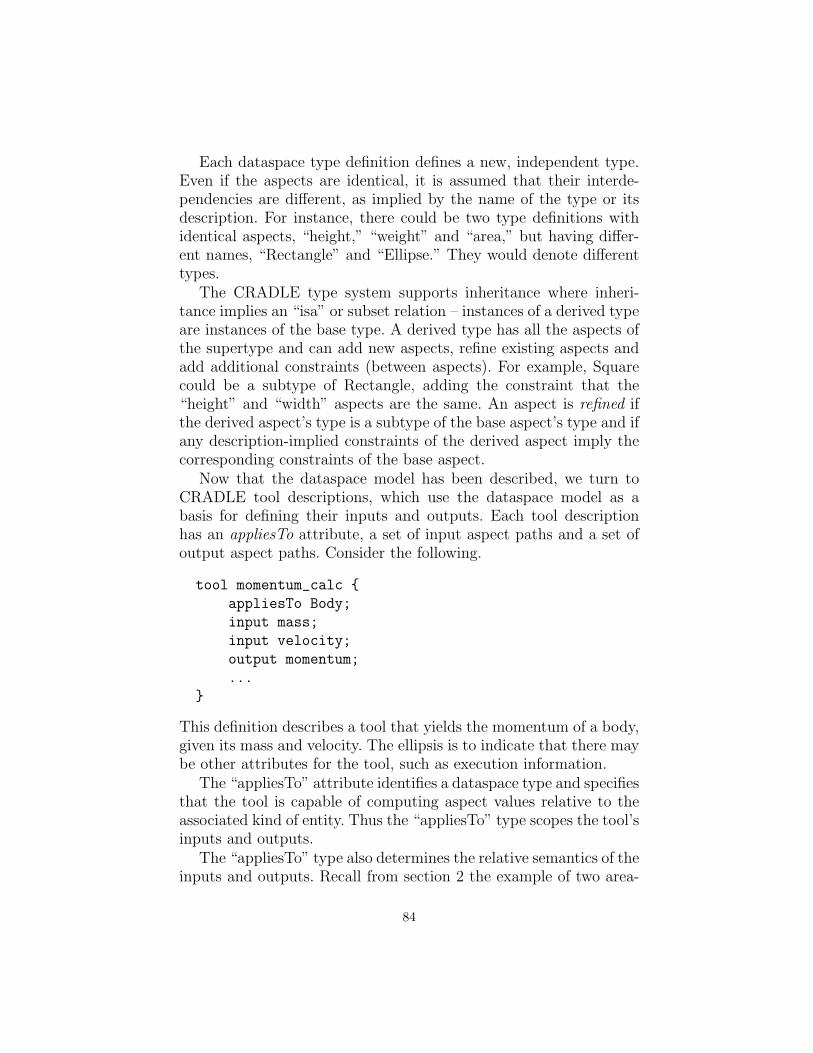
Each dataspace type definition defines a new, independent type.Even if the aspects are identical, it is assumed that their interde-pendencies are different, as implied by the name of the type or itsdescription. For instance, there could be two type definitions withidentical aspects, “height,” “weight” and “area,” but having differ-ent names, “Rectangle” and “Ellipse.” They would denote differenttypes.
The CRADLE type system supports inheritance where inheri-tance implies an “isa” or subset relation – instances of a derived typeare instances of the base type. A derived type has all the aspects ofthe supertype and can add new aspects, refine existing aspects andadd additional constraints (between aspects). For example, Squarecould be a subtype of Rectangle, adding the constraint that the“height” and “width” aspects are the same. An aspect is refined ifthe derived aspect’s type is a subtype of the base aspect’s type and ifany description-implied constraints of the derived aspect imply thecorresponding constraints of the base aspect.
Now that the dataspace model has been described, we turn toCRADLE tool descriptions, which use the dataspace model as abasis for defining their inputs and outputs. Each tool descriptionhas an appliesTo attribute, a set of input aspect paths and a set ofoutput aspect paths. Consider the following.
tool momentum_calc {
appliesTo Body;
input mass;
input velocity;
output momentum;
...
}
This definition describes a tool that yields the momentum of a body,given its mass and velocity. The ellipsis is to indicate that there maybe other attributes for the tool, such as execution information.
The “appliesTo” attribute identifies a dataspace type and specifiesthat the tool is capable of computing aspect values relative to theassociated kind of entity. Thus the “appliesTo” type scopes the tool’sinputs and outputs.
The “appliesTo” type also determines the relative semantics of theinputs and outputs. Recall from section 2 the example of two area-
84

computing tools with the same inputs and output, one for rectanglesand one for ellipses. In this case, the two tool descriptions would bethe same except one would have “appliesTo Rectangle” and the other“appliesTo Ellipse.”
4 Plan Generation and Execution
As discussed above, a dataspace type defines a vocabulary of slotnames and the semantics of their interdependencies. A tool is spec-ified with respect to some dataspace type and, so, its semantics isdetermined by the relative semantics of its inputs to outputs.
When a user uses CRADLE, he presents a problem which consistsof a problem type, a set of givens and a set of goals. The problem typeis a dataspace type and each given and goal is an aspect path relativeto the problem type. During this process, the CRADLE repositorymay be used to browse the set of types and their aspects. An exampleof a problem is as follows.
problem {
problemType Body;
given velocity;
given geometryFile;
given density;
goal momentum;
}
Given a problem, the CRADLE plan generator attempts to find aa plan, which is a directed acyclic graph of steps. Each step containsthe name of a tool and the set of prerequisite steps that it mustfollow. The plan also indicates which steps yield one or more of thegoals. The plan must be such that each tool’s “appliesTo” type is asupertype of (or possibly equal to) the problem type. Each input ofeach tool must be among the problem’s givens or among the outputsof a previous tool. Each of the problem’s goals must be among theoutputs of some tool.
The full plan generation algorithm is too complex to present here,so we give a quick summary. The algorithm uses backward chain-ing and works back from the goals. At each point it has a list,neededAspects, of aspects (really aspect paths) that need to be com-puted and a list, producedAspects, of aspects that are given or com-puted by some tool. Iteratively, it selects a needed aspect, subgoal,
85

and finds a tool, tool, whose “appliesTo” is a supertype of (or equalto) the problem type and whose outputs contain subgoal. If there isno such tool, it backtracks if possible. If there is more than one tool,it tries each in turn. To handle the “flatness” problem mentionedin section 2, the algorithm also considers applying a tool to certainsubdataspaces of the original problem, in addition to applying it atthe root. The outputs of tool are added to producedAspects and itsinputs are added to neededAspects. Also a step is allocated and addedto the plan. The iteration terminates when all neededAspects are inproducedAspects.
Plan execution is the process by which a plan is executed. It fol-lows the usual rules for executing a DAG. The dataspace modelis used to link outputs of one tool to the inputs of the next. Asmentioned earlier, the dataspace concept is logical and it is not nec-essarily the case that any real data structure directly implementsthe dataspace, although some implementations may. The purpose ofthe dataspace concept is to provide a conceptual model interrelatingtypes, tool descriptions, problem specification, plan generation andplan executions.
As examples, one implementation may directly implement thedataspace as a centralized hash table from which the tools extracttheir inputs and into which they place their outputs. Another im-plementation may instantiate a software component for each stepand use the fully qualified input and output names to hook togetherports. A third implementation might generate a script using a “man-gled” form of the aspect paths to name files or script variables thatcarry data produced by one step to later ones.
5 Status and Future Work
A CRADLE prototype has been implemented using a client-servermodel with a protocol similar to web services. The server is in Javaand accesses a MySQL database containing tables for tool and datas-pace type descriptions. The type descriptions can be used by toolspecifiers and by users posing “problems” to CRADLE. Type de-scriptions are also used during plan generation to reason about in-heritance and the types of subdataspaces. Tool descriptions are usedduring plan generation and may also be used during plan executionto obtain execution-related information.
86

For future research, we will look at applying a similar method-ology to data collections and the tools that operate on them. AsRDF[3] is a popular standard for expressing and sharing machineprocessable information on the web, we will investigate using RDF/-XML[2] in the client-server protocol. Also, we plan to look at vari-ous extensions to the dataspace model, including arrays, parameter-ized aspects (similar to methods) and parameterized types. Addingmachine-processable constraint expressions to dataspace types is an-other potential avenue of investigation.
Acknowledgments: We gratefully acknowledge the contributions of KenGee and Karen McCann in the early discussions regarding the direc-tion and design of the project.
References
1. Global Grid Forum, Semantic Grid Working Group: The Semantic Grid Vision.http://www.semanticgrid.org/vision
2. W3C: RDF/XML Syntax Specification (Revised). http://www.w3.org/TR/rdf-syntax-grammar/
3. W3C: Resource Description Framework (RDF): Concepts and Abstract. Syntax.http://www.w3.org/TR/rdf-concepts/
4. W3C: Web Services Architecture. http://www.w3.org/TR/ws-arch/5. W3C: Web Services Description Language (WSDL). http://www.w3.org/TR/-
wsdl20/
87

OWL-Based Resource Discovery forInter-Cluster Resource Borrowing
Hideki YOSHIDA, Nobuo SAKIYAMA, Toshibumi SEKI,Tatsunori KANAI, and Tetsuro KIMURA
Toshiba Corporation, Corporate Research & Development Center,Komukai-Toshiba-Cho 1, Saiwai-ku, Kawasaki 212-8582, Japan
Abstract. To improve the resource adjustment capability of businessapplication cluster systems, we have devised a new grid system in whichclusters borrow lower-level computing resources from each other. Hetero-geneous resources that coexist in these clusters are described using OWLWeb Ontology Language (OWL) to realize a flexible resource discovery.In this paper we present its system structure and OWL-based resourcediscovery.
1 Current Business Application Cluster Systems andTheir Problem
In contrast to traditional grid systems whose main target is scientificand engineering computation, our research focuses on cluster sys-tems used for business applications such as web application servers,content management systems, or groupware systems.
These applications often show high load fluctuations according todate and time, and at the same time have severe service level require-ments such as response time, calling for an alternative approach toconventional grids.
In these systems, jobs are executed as shown in Figure 1.
ClusterManager
Node
Job
Job
Cluster
Job
Node
Job
Job
Fig. 1. Job execution in current cluster systems

The Cluster Manager controls the execution of jobs in a clusterand assures failover of jobs in case of a hardware or software failure.The resource assignment in the cluster is managed centrally to reflectthe resource allocation policy of that cluster.
If there is an overloaded node in the cluster, jobs are moved fromone node to another (as shown with an arrow in Figure 1) to adjustthe load.
Such adjustments limited to a single cluster cannot cope with anextremely high load, causing performance degradations such as adelay in response time.
Furthermore, if nodes reserved for provisioning purposes are usedup to cope with a fault or an overload, redundancy against furtherfaults or further overloads cannot be secured.
To solve these problems, resource adjustment that spans multipleclusters is demanded. We want to realize this resource adjustmentby connecting multiple clusters in a grid-like way.
The traditional approach for connecting cluster systems into agrid is shown in Figure 2. Jobs are either submitted to the grid andallocated to a cluster, or the execution of a job is delegated from onecluster to another cluster.
ClusterManager
ClusterManager
Job
Job
Job
Job
Node
Job
Node
Job
Job
Node
Job
Node
Job
Job
Node
Cluster
Fig. 2. Conventional method to form a grid by connecting clusters
A problem of this approach is that the execution of jobs cannoteasily be assured at the level realized in cluster systems. In a clustersystem, the cluster manager typically uses a heartbeat and a quo-rum mechanism for a reliable fault detection and job failover. Suchmechanisms are usually not available to jobs submitted to a grid.
Another problem is the lack of practical mechanisms to reflecta resource allocation policy to another cluster. Setting priorities tojobs or allocating a job to a specific node is not too difficult within a
89

cluster, but in order to apply such allocation policy to jobs submittedto a grid, an elaborate mechanism and a new protocol are needed.
In these respects, this conventional method of grid deploymenthas a wide discrepancy with the job management in current businessapplication cluster systems.
2 Inter-Cluster Resource Borrowing
As an alternative to the conventional method of grid deploymentdiscussed above, we have devised an approach that we call inter-cluster resource borrowing and is more suited to the resource and jobmanagement model in current cluster systems. Its overall structureis shown in Figure 3.
ClusterManager
ClusterManager
Job
Job
Job
Job
Node
Job
Node
Job
Job
Job
Node
Job
Borrow a node fromanother cluster
Resource Request
Job
Node Node
Job
Cluster A Cluster B
Fig. 3. Abstract structure of inter-cluster resource borrowing
In this approach, each cluster operates as a natural extensionof the current cluster. The resource borrowing between clusters isimplemented at the dedicated layer that we call grid layer.
If Cluster A in Figure 3 is suffering an overload or a fault thatcannot be made up for by an adjustment within Cluster A, the clus-ter manager of Cluster A issues a resource request to the grid layer.The cluster manager of Cluster B is notified of that request in orderto transfer some node from Cluster B to Cluster A.
After the node transfer, jobs are moved to the acquired node toaccomplish the load adjustment within Cluster A.
The node transfer can be implemented in various ways. Networkboot is the node transfer mechanism that we think most promising.As an instance of network boot mechanisms, we are investigating
90

SAN boot. SAN boot is a mechanism to change the correspondenceof a node to a boot image on a disk by placing boot images ona disk on a storage area network (SAN). By using the SAN bootmechanism, a node borrowed from another cluster can be bootedwith the boot image of the borrowing cluster, making it easier toplace the node under the control of the borrowing cluster.
In addition to the network boot, virtualization methods such asvirtual machines can also be employed to realize node transfer.
In conventional grids, a resource was managed by a fixed clusterand jobs were moving across clusters. In an inter-cluster resourceborrowing system, the execution of a job is always control by a fixedcluster, and it is the resources that move across clusters.
A major problem of implementing this system is the discovery ofresources to be borrowed. We will discuss it in the next section.
3 Resource Discovery from Heterogeneous Resources
A business application cluster, which is the target of the inter-clusterresource borrowing, has usually multiple application programs run-ning on it. These applications often run on different operating sys-tems and/or on processor architectures. In addition to this inter-nal heterogeneity of a single cluster, clusters are usually constructedwith their own goals in mind, so there is a high heterogeneity amongclusters.
Furthermore, resources that are physically equivalent can differ inthe area or domain in which they can be used. For example, a bootimage on a SAN disk can only be used from a node that is connectedto the SAN.
In these regards, there is a great deal of diversity among availableor required resources.
Inter-cluster resource borrowing calls for a technology to discoveradequate resources efficiently from these diversified resources.
In order to perform this discovery, both a description mechanismand a matching mechanism are needed. We will discuss them below.
3.1 Description of Heterogeneous Resources
Resources that are target of this discovery should be described insome way. In addition, a mechanism to specify requirements towarddesired resources is necessary.
91

In OGSA (Open Grid Services Architecture) [1] and Globus Toolkit[3], which is its reference implementation, a resource can be describedby a service data. However, requirements can be handled only in avery limited way. For example, GLUE Computing Element (CE) [4]used in Globus can describe hardware resources, but dependency be-tween resources (such as a server and a disk that can be connected toit) cannot be described. Descriptions to handle network topology orbandwidth are also lacking. Resource Specification Language (RSL)[5] has a limited capability to express requirements of an applicationprogram, but the RSL description is not currently matched againstformal resource descriptions.
It is possible to make a new fixed specification (or a fixed exten-sion of these existing specifications) for the resource description, butin order to describe diversified resources including those yet to come,a more flexible method of resource description is preferred.
3.2 Use of OWL
To describe these wanted and available resources, we have introducedthe OWL Web Ontology Language (OWL)[6]. In the sense that weare using a Semantic Web technology for implementing a kind of gridinfrastructure, our study can be classified to a Semantic Grid[7].
By using OWL, off-the-shelf inference engines that support OWLcan be used for matching of resource descriptions. In addition, aflexible resource description is realized as follows.
InstanceDescription
RequirementDescription
ModelDescription
InferenceEngine
“A cluster has physical nodes.Each node is of som e
architecture.”
“Cluster1 has a physical node called Node1.Node1 is of x86 architecture.”
“I want a physical node
of x86 architecture.”
SearchResult
“Cluster1 is likely to have that resource.”
Fig. 4. Matching of OWL descriptions
92

As shown in Figure 4, three kinds of OWL descriptions are in-volved:
1. Model Description.General concepts and their relations are defined here.
2. Instance Description.Actual resources in given clusters are described here based on theabove model.
3. Requirement Description.Requirements toward resources that a cluster wants to borroware stated here also based on the same model.
As model itself is also written in OWL and loaded at runtime,a new model to describe additional resources can be incorporatedwithout modifying the source code of the grid layer (though thecluster manager itself should be able to process the new resourcedescriptions).
Details of the OWL usage are stated in Section 6.
4 Overall System Structure
The overall structure of our implementation is shown in Figure 5.
ResourceDescription
ResourceDescription
Node Node Node
Cluster Manager
ResourceInform ation
ResourceInform ation
NodeRequest
Node Request
Grid LayerGridAgent
GridAgent
Node TransferCluster Manager
GridManager
OGSI-Based Protocol
Fig. 5. Overall structure of inter-cluster resource borrowing system
93

This system is composed of two layers: the cluster layer and thegrid layer. They have following responsibilities:
– Cluster layer.• Execution control of jobs• Resource management and allocation within the cluster
– Grid layer.• Global adjustment of resource allocation• Sharing of resource information• Processing of resource request• Aggregation and resolution of resource requirements• Determination of candidate clusters to provide resource• Processing of node transfer
Of these, the grid layer is further divided into following two com-ponents:
– Grid agent.A grid agent resides in each cluster and provides the interfacebetween the grid layer and the cluster.In addition to the mutual transfer of resource information, theaggregation of resource information is also performed here.
– Grid manager.A grid service to perform the grid-wide processing. Part of theresource information is stored here.
A prototype of this system is currently being implemented asservices on Globus Toolkit 3 (GT3).
5 Two-Phase Resource Discovery
The resource information consulted at the resource discovery spanfrom static to dynamic. If we can manage all the information cen-trally on the grid manager, the resource discovery can be efficientlycontained to the grid manager. However, if all the resource informa-tion is to be registered frequently to the grid manager, its load mayrise excessively and ruin the scalability of the grid. Furthermore, adynamic information that change without intervention of the gridagent or the cluster manager cannot be registered to the grid man-ager consistently.
Therefore, we separated the resource discovery into two phases:
94
Phase 1: Candidate cluster discovery at the grid managerPhase 2: Resource discovery at the grid agent
Some of the resource information is consulted in both phases, andothers are referenced only in the second phase. The criteria of thisclassification are discussed below.
We assume that resource information can be classified into threecategories:
Category 1: Static resource information.Changes itself rarely and can be registered or cached to the gridmanager. The operating system or the processor architecture ofa server are examples of information of this category.
Category 2: Dynamic resource information determined by the clus-ter manager.The resource information that changes dynamically under thecontrol of the cluster manager. These changes can be notifiedfrom the cluster manager to the grid manager to keep the infor-mation at the grid manager consistent. The kind and the numberof jobs running on a node can be classified here.
Category 3: Dynamic resource information determined by compo-nents other than the cluster manager.The cluster manager does not directly affect changes of this re-source information. The network topology information includingconnectivity, bandwidth or delay is an example of the informationof this category.
In this system, the resource information of Category 1 and 2 istransferred from the grid agent to the grid manager and registeredthere. Phase 1 of the resource discovery depends only on the infor-mation of these two categories. In Phase 2, the resource informationof Category 3 is measured dynamically, and the information of allthree categories is used to determine the resource to be borrowed.
6 Resource Description and Constraint Resolution UsingOWL
As stated in Section 3.2, we are using OWL to describe resources andresource requirements. There are three sublanguages of OWL: OWLLite, OWL DL (description logics), and OWL Full. Of these, OWL
95

Full allows most flexible descriptions, but there is no guarantee thatOWL Full descriptions can be processed in finite time, so it is notfeasible here. On the other hand, while OWL Lite descriptions aremost simple and can be processed most efficiently, some functional-ities not included in OWL Lite (such as owl:oneOf) were necessary.Therefore, we have selected OWL DL, whose description capabil-ity and computation complexity appears appropriate, for resourcedescriptions.
Currently we are using Jena 2.1[8], which has a full support ofOWL Lite and a partial support of OWL DL, as the inference engine.
Host
PhysicalHost
BorrowableEntityIdentifiableEntity boolean
ArchitectureanyURI
borrowable
isArchitecureOfinformationServiceURL
subClassOfsubClassOf
subClassOf
Fig. 6. Partial Example of Model Description
In the current prototype, we are using a handwritten OWL modelwith many elements derived from GLUE CE. An example model isshown in Appendix A and its partial structure is shown in Figure 6.PhysicalHost is a resource that share properties of Host includingthe processor architecture, but has additional properties includingconnectivity to a network.
Appendix B shows an requirement description based on this model.This description is used in a request to find a cluster which has aphysical node that can boot a specific logical node (lnode1). Thefirst class in this description defines a cluster which has a desiredphysical host. Three restrictions to this physical host are describedin the definition of the second class: It should be borrowable, shouldbe of the same architecture as lnode1, and should share a storagearea network with the network storage that hosts the boot image oflnode1.
96

We are planning to develop tools to automatically convert descrip-tions written in extended GLUE CE or in cluster-native formats toOWL. CIM(Common Information Model)-based standards [9] arealso candidates of resource information sources.
7 Implementation Status and Future Directions
A stand-alone prototype (i.e. without connection to a real clustermanager) of the grid layer is already runnable. The resource dis-covery using the requirement description in OWL and the resourcerequest is realized. The node transfer is currently just simulated.
Following extensions are planned:
– Interface to real cluster managers.In order to realize an actual node transfer, at least some func-tionality of a real cluster manager is needed. We are examiningfeasibility of several clustering software (including our in-houseproduct cluster manager) to connect to our grid layer.
– Policy handling in resource discovery.Besides hardware and software property of resources, policiessuch as the security or service level policy should be respectedin the resource discovery. We are investigating ways to incorpo-rate policy descriptions into the OWL-based resource discovery.
– Aggregation of resource information.Registering resource information of individual resources to thegrid manager entails a high processing time at the registrationand the first phase of resource discovery. It would be desirable ifwe can make a summarized version of the resource informationand register it to the grid manager for a faster resource discov-ery. Depending on applications, a certain degree of false positivesof resource information can be allowed, as the second phase re-alizes an accurate discovery of resources. If overlooking availableresources is acceptable, false negatives are also allowed. [11] men-tions to an aggregation function that is related to our idea.
8 Conclusion
In this paper, we have illustrated a problem of current business appli-cation cluster systems, and how the inter-cluster resource borrowing
97

can be applied to cope with that problem. By using OWL for thedescription of resources to be borrowed and using an OWL engineas the matching mechanism, a flexible resource discovery is realized.
We are going to further implement this architecture. Resourceborrowing between clusters in a data center is targeted first, andwe aim to support borrowing between clusters that span wide-areanetworks as future prospects.
References
[1] The Physiology of the Grid: An Open Grid Services Architecture for DistributedSystems Integration, Ian Foster, Carl Kesselman, Jeffrey M. Nick, and StevenTuecke, OGSI-WG document, June 2002.
[2] Open Grid Services Infrastructure (OGSI) Version 1.0, S. Tuecke, K. Czajkowski, I.Foster, J. Frey, S. Graham, C. Kesselman, T. Maguire, T. Sandholm, P. Vanderbilt,and D. Snelling, OGSI-WG document, June 2003.
[3] Globus Toolkit 3 Core — A Grid Service Container Framework, Thomas Sandholmand Jarek Gawor, whitepaper, July 2003.
[4] Sharing a Conceptual Model of Grid Resources and Services, Sergio Andreozzi andCristina Vistoli, Conference for Computing in High Energy and Nuclear Physics,March 2003.
[5] A Resource Management Architecture for Metacomputing Systems, K. Czajkowski,I. Foster, N. Karonis, C. Kesselman, S. Martin, W. Smith and S. Tuecke, in 4thWorkshop on Job Scheduling Strategies for Parallel Processing, Springer-Verlag,1998.
[6] OWL Web Ontology Language Reference, Mike Dean and Guus Schreiber, Editors,W3C Recommendation, February 2004.
[7] Semantic Grid and Pervasive Computing, David De Roure, GGF9 Semantic GridWorkshop, October 2003.
[8] Jena: Implementing the Semantic Web Recommendations, Jeremy J. Carroll, IanDickinson, Chris Dollin, Dave Reynolds, Andy Seaborne, Kevin Wilkinson, HPTechnical Report HPL-2003-146, December 2003.
[9] DMTF Announces New Working Group for Utility Computing, Press Release,Distributed Management Task Force, February 2004.
[10] Interoperability of Grid Resource Descriptions: A Semantic Approach, JohnBrooke, Kevin Garwood and Carole Goble, GGF9 Semantic Grid Workshop, Oc-tober 2003.
[11] Knowledge Discovery and Ontology-based services on the Grid, Mario Cannataro,GGF9 Semantic Grid Workshop, October 2003.
98

A Example OWL ModelDescription
<owl:Class rdf:ID="BorrowableEntity" /><owl:Class rdf:ID="IdentifiableEntity" /><owl:Class rdf:ID="BootableEntity" /><owl:Class rdf:ID="Cluster">
<rdfs:subClassOfrdf:resource="#IdentifiableEntity" />
</owl:Class><owl:Class rdf:ID="Host">
<rdfs:subClassOfrdf:resource="#BorrowableEntity" />
<rdfs:subClassOfrdf:resource="#IdentifiableEntity" />
</owl:Class><owl:Class rdf:ID="PhysicalHost">
<rdfs:subClassOf rdf:resource="#Host" /></owl:Class><owl:Class rdf:ID="LogicalHost">
<rdfs:subClassOf rdf:resource="#Host" /><rdfs:subClassOfrdf:resource="#BootableEntity" />
</owl:Class><owl:Class rdf:ID="Network" /><owl:Class rdf:ID="StorageNetwork">
<rdfs:subClassOf rdf:resource="#Network" /></owl:Class><owl:Class rdf:ID="SAN">
<rdfs:subClassOfrdf:resource="#StorageNetwork" />
</owl:Class><owl:Class rdf:ID="Storage" /><owl:Class rdf:ID="NetworkStorage">
<rdfs:subClassOf rdf:resource="#Storage" /><rdfs:subClassOf rdf:resource="#Host" />
</owl:Class><owl:Class rdf:ID="StoragePartition" /><owl:Class rdf:ID="Architecture">
<owl:oneOf rdf:parseType="Collection"><owl:Thing rdf:about="#i386" /><owl:Thing rdf:about="#powerpc" />
</owl:oneOf></owl:Class><Architecture rdf:ID="i386" /><Architecture rdf:ID="powerpc" /><owl:DatatypeProperty rdf:ID="borrowable">
<rdfs:domain rdf:resource="#BorrowableEntity" /><rdfs:range rdf:resource="&xsd;boolean" />
</owl:DatatypeProperty><owl:DatatypePropertyrdf:ID="informationServiceURL"><rdfs:domain rdf:resource="#IdentifiableEntity" /><rdfs:range rdf:resource="&xsd;anyURI" />
</owl:DatatypeProperty><owl:ObjectProperty rdf:ID="controls">
<rdfs:domain rdf:resource="#Cluster" /><rdfs:range rdf:resource="#Host" />
</owl:ObjectProperty><owl:ObjectProperty rdf:ID="isOfArchitecture">
<rdfs:domain rdf:resource="#Host" /><rdfs:range rdf:resource="#Architecture" />
</owl:ObjectProperty><owl:ObjectProperty rdf:ID="isArchitectureOf">
<owl:inverseOf rdf:resource="#isOfArchitecture" /></owl:ObjectProperty><owl:ObjectProperty rdf:ID="connects">
<rdfs:domain rdf:resource="#Network" /><rdfs:range rdf:resource="#Host" />
</owl:ObjectProperty><owl:ObjectProperty rdf:ID="isConnectedTo">
<owl:inverseOf rdf:resource="#connects" /></owl:ObjectProperty><owl:ObjectProperty rdf:ID="connectsPhysicalHost">
<rdfs:subPropertyOf rdf:resource="#connects" /><rdfs:domain rdf:resource="#Network" /><rdfs:range rdf:resource="#PhysicalHost" />
</owl:ObjectProperty><owl:ObjectPropertyrdf:ID="isConnectedPhysicalHostTo">
<owl:inverseOfrdf:resource="#connectsPhysicalHost" />
</owl:ObjectProperty><owl:ObjectProperty rdf:ID="connectsNetworkStorage">
<rdfs:domain rdf:resource="#Network" /><rdfs:range rdf:resource="#NetworkStorage" />
</owl:ObjectProperty><owl:ObjectProperty rdf:ID="includes">
<rdfs:domain rdf:resource="#Storage" /><rdfs:range rdf:resource="#StoragePartition" />
</owl:ObjectProperty><owl:ObjectProperty rdf:ID="hosts">
<rdfs:domain rdf:resource="#StoragePartition" /><rdfs:range rdf:resource="#LogicalHost" />
</owl:ObjectProperty>
B Example OWLRequirementDescription
<owl:Class rdf:ID="ClustersIWantNow"><owl:intersectionOf rdf:parseType="Collection">
<owl:Class rdf:about="&cst;Cluster" /><owl:Restriction>
<owl:onProperty rdf:resource="&cst;controls" /><owl:someValuesFromrdf:resource="#PhysicalHostsIWantNow" />
</owl:Restriction></owl:intersectionOf>
</owl:Class><owl:Class rdf:ID="PhysicalHostsIWantNow">
<owl:intersectionOf rdf:parseType="Collection"><owl:Class rdf:about="&cst;PhysicalHost" /><owl:Restriction>
<owl:onPropertyrdf:resource="&cst;borrowable" />
<owl:hasValue rdf:datatype="&xsd;boolean">true
</owl:hasValue></owl:Restriction><owl:Restriction>
<owl:onPropertyrdf:resource="&cst;isOfArchitecture" />
<owl:someValuesFrom><owl:Restriction>
<owl:onPropertyrdf:resource="&cst;isArchitectureOf" />
<owl:hasValue rdf:resource="#lnode1" /></owl:Restriction>
</owl:someValuesFrom></owl:Restriction><owl:Restriction>
<owl:onProperty rdf:resource="&cst;isConnectedPhysicalHostTo" />
<owl:someValuesFrom><owl:Restriction>
<owl:onProperty rdf:resource="&cst;connectsNetworkStorage" />
<owl:someValuesFrom><owl:Restriction>
<owl:onPropertyrdf:resource="&cst;includes" />
<owl:someValuesFrom><owl:Restriction>
<owl:onPropertyrdf:resource="&cst;hosts" />
<owl:hasValuerdf:resource="#lnode1" />
</owl:Restriction></owl:someValuesFrom>
</owl:Restriction></owl:someValuesFrom>
</owl:Restriction></owl:someValuesFrom>
</owl:Restriction></owl:intersectionOf>
</owl:Class>
99