gillette madison pipeline project (gmpp) technical
TRANSCRIPT

GILLETTE MADISON PIPELINE PROJECT (GMPP)
TECHNICAL MEMORANDUM #13
TO: Mike Cole, P.E., City of Gillette FROM: Darin Brickman, P.E., BMcD
Jason Schaefer, EIT, BMcD DATE: July 20, 2010 JOB NO.: BMcD # 54432, MMI #4776.001 RE: Evaluation of Disinfection Alternatives CC: ATTACHMENTS:
Carl Anderson, P.E., MMI Dan Korinek, P.E., BMcD Casey Hanson, P.E. MMI Bryan Clerkin, P.E., WWDC
Urgent For Review Please Comment Please Reply For Your Use
INTRODUCTION AND BACKGROUND
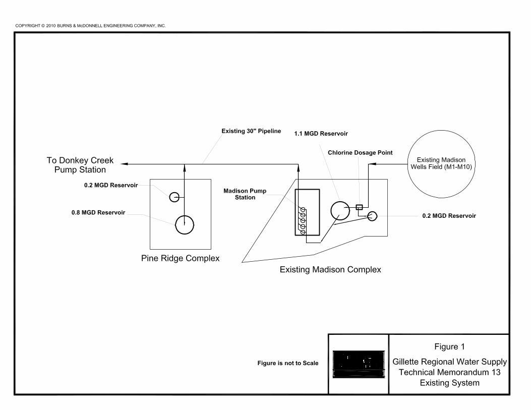
The City of Gillette currently utilizes 26 groundwater wells to provide potable drinking water to their customers. Ten (10) of the wells penetrate the Madison aquifer and 16 wells penetrate the Fort Union and Fox Hills/Lance aquifers. Fort Union and Fox Hills/Lance wells discharge to Pump Station #1 (PS1) where chlorination occurs. Madison water is pumped from the wells and chlorinated prior to entering two storage reservoirs located on the Madison Pumping Station site. These reservoirs feed the Madison Pumping Station which delivers the water to two storage reservoirs at the Pine Ridge site. From the Pine Ridge storage reservoirs the water flows by gravity to the Donkey Creek Pump Station where it is once again “boosted” to the City of Gillette. The Madison Pump Station site has two storage reservoirs, a 1.1 million gallon (MG) reservoir constructed in the early 1980s and a 0.2 MG reservoir constructed in the mid-2000’s. The Madison Pump Station also contains gaseous chlorine feed equipment. Chlorine solution is added in a meter vault located just east of the 1.1 MG storage reservoir. The Pine Ridge

Technical Memorandum #13 Subject: Evaluation of Disinfection Alternatives July 20, 2010 Page 2 of 14 storage reservoirs include one 0.8 MG reservoir built in the early 1980s and one 0.2 MG reservoir built in the mid-2000’s. The existing Madison and Pine Ridge facilities are illustrated in Figure 1. A Madison well field expansion is proposed near the existing Madison and Pine Ridge locations. Technical Memorandum #2 discusses the new well field siting in detail. The new Madison well field will require either a dedicated disinfection system or a larger overall disinfection system to serve the entire Madison supply to provide chlorine residual. This technical memorandum discusses alternatives for disinfection of water from the Madison systems.
WDEQ REGULATIONS
The Wyoming Department of Environmental Quality standards regarding disinfection were reviewed to determine the applicable requirements for the disinfection system. Table 1 summarizes the requirements for the disinfection system applicable to this project. The WDEQ does not have specific standards for the on-site sodium hypochlorite generation systems, nor does it have specific redundancy standards for chemical feed equipment.
Table 1. Applicable WDEQ Disinfection Requirements Chapter Section Page(s) Description
12 10 12-41 Where free chlorine residual is provided, 1/2
hour contact time shall be provided for ground waters.
12 10 12-40 Chlorination Equipment - The chlorinator
capacity shall be such that a minimum 5 mg/L disinfection dose can be added on the
maximum day.
12 11 12-56 Chemical feeders and pumps operate at no lower than 20 percent of the feed range.
12 11 12-57 Storage space or tank volume shall be
provided for at least 30 days of chemical supply.
ON-SITE SODIUM HYPOCHLORITE SYSTEMS
The City of Gillette had internal discussions of alternative disinfection methods including gaseous chlorine, bulk sodium hypochlorite delivery, and on-site sodium hypochlorite generation disinfection. Based on this discussions the City determined that on-site sodium hypochlorite generation was desired for this project primarily due to safety considerations. On-site generation of liquid sodium hypochlorite is typically achieved through the use of commercially available systems. These systems generally consist of a supply water softening device, brine saturator, transformer/rectifier, electrolyzer, sodium hypochlorite storage tank(s), control panel, and metering pumps which are depicted in Figure 2.

Technical Memorandum #13 Subject: Evaluation of Disinfection Alternatives July 20, 2010 Page 3 of 14
Figure 2. On-site Sodium Hypochlorite Operational Schematic
System Components
• Softener: The water used for the saturator and dilution of the brine solution must have less than 17 mg/l hardness (as CaCO3), otherwise operating efficiency and maintenance-free operation will be compromised. The existing Madison well water has approximately 490 mg/l hardness (as CaCo3). Therefore, softening must be provided as part of the overall system.
• Brine Saturator: The saturator allows the salt supply to be stored indefinitely in
sufficient quantity to provide production continuity and economical refill cycles. The salt is stored wet with the make-up water entering above the salt bed. The water passes through the salt bed, forming a saturated brine solution of approximately 32% strength. The brine saturator also serves as a storage tank with a 30-day capacity of brine solution at the maximum flow and dosage rates and includes space for the un-dissolved salt.
• Transformer/Rectifier: A transformer/rectifier is used to provide the necessary low-
voltage DC power required to drive the electrolyzer. DC current control accuracy is provided to ensure high operating efficiency.

Technical Memorandum #13 Subject: Evaluation of Disinfection Alternatives July 20, 2010 Page 4 of 14
Electrolyzer: The electrolyzer represents the “heart” of the process. The electrolyzer contains a chassis to which the cathodes and anodes are fixed in a configuration that ensures maximum operating efficiency. Each electrolyzer contains cells electrically connected in series, containing sufficient anodes and cathodes to produce the desired quantity of chlorine.
• Sodium Hypochlorite Storage Tank: The storage tank stores sufficient sodium hypochlorite for ready use and provides for the release and removal of hydrogen produced by the generation process. Generally, storage is provided for at least 24 to 48 hours of operation. Level probes in the tank provide start/stop control of the process to maintain a continuous supply of product. Typically, air blowers mounted on or near the tank dilute the hydrogen below the flammability limit and force ventilate the tank to an outside discharge.
• Control Panel: The entire process is automatically operated and monitored by a central control panel. Operational functions are continuously monitored to ensure that the system is operating correctly, and it provides alarm functions and a shutdown sequence in the event of a malfunction. Larger systems can be programmed to make use of "off-peak" power to take advantage of lower power costs.
• Metering Pumps: Either positive displacement or centrifugal metering pumps provide sodium hypochlorite to the treatment process. The metering pumps draw chemical from the product storage tanks and can be controlled by the main system control panel.
Supply water passes through the water softener to remove any calcium, magnesium, iron and manganese present. Softened water is added to the brine saturator to produce the brine solution. The brine solution is then pumped from the saturator to the electrolyzer. The dilution water (also softened) is combined with the saturated brine solution to form a 3% brine solution before entering the electrolyzer.
Within the electrolyzer, the brine solution carries a current applied between the positive and negative electrodes, thus electrolyzing the brine solution. This results in chlorine (Cl2) gas being produced at the positive electrode (anode), while sodium hydroxide (NaOH) and hydrogen (H2) gas are produced at the negative electrode (cathode). The chlorine gas further reacts with the hydroxide to form sodium hypochlorite (NaOCl). This reaction can be simplified as follows:
NaCl + H2O + Electricity → NaOCl + H2
When the solution exits the electrolyzer, it is approximately 0.8% strength sodium hypochlorite.
The 0.8% sodium hypochlorite solution, together with the hydrogen by-product produced during electrolysis, are discharged into the sodium hypochlorite storage tank. The hypochlorite

Technical Memorandum #13 Subject: Evaluation of Disinfection Alternatives July 20, 2010 Page 5 of 14 solution is fed to the point of application by a metering pump. Level probes in the storage tank start and stop the electrolyzer to maintain a consistent hypochlorite supply.
The operating temperature of the feed water should be between 50° and 80° F. Temperatures outside this range may require additional conditioning. Low water temperatures will affect the anode surfaces and below 50° F, shorten their life. For this reason, heat exchangers are recommended where cold water conditions are likely to exist. At a temperature greater than 80° F the process efficiency will drop. Water consumption is approximately 15 gallons per lb. of available chlorine produced.
It is recommended that the salt added to the saturator be at least 99.8% pure, food grade, and vacuum dried. Approximately 3.0 lbs of salt are required for each pound of equivalent chlorine produced. This may vary depending on feed water hardness, salt quality, and temperature.
Sodium Hypochlorite Generator Sizing The sodium hypochlorite generation system will be sized for the combined new and existing Madison well flow rates at the required 5 mg/L dose. However, the existing gaseous chlorine system at the Madison Pump Station typically doses between 0.5 mg/L and 1.5 mg/L. Therefore, the WDEQ criteria are expected to result in a substantially conservative generator system size. This should be kept in mind when considering redundancy and designing for maintenance situations. Two generators each sized for 50% of the total required system production are recommended to allow for maintenance. Redundancy for the generator will be accomplished by designing the storage tanks and chemical feed system for 10-12.5% sodium hypochlorite solution at the maximum flow rate and dosage. If the on-site sodium hypochlorite system is out-of-service for maintenance or repair, sodium hypochlorite could still be provided via bulk delivery. The system will be designed with the following design criteria as summarized in Table 2 for the ultimate build out of the system. In the construction phasing section more information has been provided on the design criteria for each phase.
Table 2. Design Criteria Generator Size Two (2) or more systems
Peak Day Flow = 40.2 MGD Maximum Dosage = 5 mg/L
Brine Storage One (1) FRP Tank 30 Days
Sodium Hypochlorite Storage Two (2) FRP Tanks 2 Days Capable of storing 12.5% bulk delivery
Chemical Metering Pumps 0.5 mg/L at 0.13 MGD 5 mg/L at 40.2 MGD No turndown <20% of feed range.
On-site sodium hypochlorite generation system manufacturers were contacted regarding system/generator sizes. These sizes are addressed in each scenario below.

Technical Memorandum #13 Subject: Evaluation of Disinfection Alternatives July 20, 2010 Page 6 of 14 Existing Madison Wells As indicated in Technical Memorandum #5, the existing Madison wells (M-1 through M-10) have a total capacity of 11.1 MGD (7,734 gpm while the firm capacity is 9.5 MGD (6,565 gpm)). The Madison Pump Station has a total capacity of 14 MGD (9,700 gpm) with a firm capacity of 10 MGD (7,000 gpm). The on-site sodium hypochlorite system would be designed for the total capacity of the pump station allowing the potential addition of another well to the existing Madison well field. Table 3 shows the required capacity of the Madison sodium hypochlorite generation system at the maximum flow rate of 14 MGD (9,700 gpm) and a range of dosages from 1 mg/L to 5 mg/L.
Table 3. Existing Madison Wells Generator Capacity at 14 MGD
Dosage Generator Size
mg/L lbs/day 1 117 2 234 3 350 4 467 5 584
The system would include two generators each sized for at least 300 lbs/day. The closest available capacities range from 300 to 500lbs/day. The actual system size will not be known until a manufacturer is chosen due to varying system sizes available from manufacturers. Two sodium hypochlorite storage tanks, minimum 8,800 gallons each, would be provided along with a brine storage tank in excess of 5,600 gallons.
New Madison Wells As indicated in Technical Memorandum #3, the required new firm capacity of the Madison wells will be 16,000 gpm. Given an estimated well production of 1,400 gpm, a total of 12 wells would meet the firm capacity requirement. As such, a total of 13 new wells will ultimately be installed in the new Madison well field with a total capacity of 18,200 gpm, or 26.2 MGD. Table 4 shows the required capacity of a sodium hypochlorite generation system for the new Madison wells at the assumed maximum flow rate and a range of dosages from 1 mg/L to 5 mg/L.
Table 4. New Madison Wells Generator Capacity at 26.2 MGD
Dosage Generator Size
mg/L lbs/day 1 219 2 437 3 656 4 874 5 1,093
The system would include two generators each sized for at least 550 lbs/day. The closest available capacities are 600 lbs/day. Two sodium hypochlorite storage tanks, minimum 16,500 gallons each, would be provided along with a brine storage tank in excess of 10,500 gallons.

Technical Memorandum #13 Subject: Evaluation of Disinfection Alternatives July 20, 2010 Page 7 of 14 Combined New and Existing Madison Wells The capacity of the on-site sodium hypochlorite system would be large enough for both the existing Madison wells (14 MGD) and the new Madison wells (26.2 MGD) for a maximum capacity of 40.2 MGD. Table 5 shows the required capacity of the Madison sodium hypochlorite generation system at the maximum flow rate (40.2 MGD) and a range of dosages from 1 mg/L to 5 mg/L.
Table 5. Generator Capacity for all Madison Wells at 40.2 MGD
Dosage Generator Size
mg/L lbs/day 1 335 2 671 3 1,006 4 1,341 5 1,676
The system would include multiple generators sized for at total capacity of at least 1,676 lbs/day. Depending on the manufacturer, the unit sizes can range from 500 to 1,000 lbs/day. One manufacturer is available in 900 lbs/day units and would include two units. Another manufacturer would have one 1000 lb/day unit and two 500 lb/day units. Yet another manufacturer would have three 600 lb/day units. The actual system size will not be known until a manufacturer is chosen due to varying system sizes available from manufacturers. Two sodium hypochlorite storage tanks, minimum 25,000 gallons each, would be provided along with a brine storage tank in excess of 16,000 gallons.
Sodium Hypochlorite Storage Two sodium hypochlorite storage tanks will be designed to contain a two-day supply of 0.8% sodium hypochlorite solution. Providing two days of storage will allow the on-site sodium hypochlorite generation system to run at a constant rate while demand varies throughout the day. It will also allow time for bulk delivery of sodium hypochlorite if the generator requires significant down time for maintenance or repair. Both sodium hypochlorite tanks will be designed to accommodate storage of 10-12.5% sodium hypochlorite. The sodium hypochlorite storage tanks should be located inside a sodium hypochlorite generation facility. Three materials are acceptable for storage of sodium hypochlorite including; high density polyethylene (HDPE), cross linked polyethylene (XLPE), and fiberglass reinforced plastic (FRP). FRP tanks are typically used for larger volume chemical storage tanks.
Brine Saturator The brine saturator/storage tank can be located outside the proposed sodium hypochlorite generation facility to reduce the required building footprint. Three different materials can be used for the brine vessel including; HDPE, XLPE, and FRP. FRP tanks are typically used for larger volume storage. If the brine vessel is located outside, it should be designed with heat tracing and insulation to protect it from the elements.
Chemical Feed Pumps The sodium hypochlorite feed system will be required to deliver both 0.8% sodium hypochlorite solution generated on-site and 12.5% sodium hypochlorite solution delivered in bulk at the

Technical Memorandum #13 Subject: Evaluation of Disinfection Alternatives July 20, 2010 Page 8 of 14 minimum and maximum dosages and at the required system head pressure. The turndown required to accomplish all dosages, flow rates, and sodium hypochlorite concentrations is too high for a single peristaltic pump generally used in this application. Peristaltic metering pumps are recommended because sodium hypochlorite degrades and produces chlorine gas in the process. This gas can interfere with the operation of diaphragm metering pumps. All chemical feed systems will include isolation valves, pressure relief valves, backpressure valves, and other piping accessories to ensure a properly operating and functional system. Two methods are available to meet the turndown requirements of this system. First, utilizing two chemical feed pumps (one for 0.8% solution and one for 12.5% solution) at every dosing location. Second, dilute the 12.5% solution to a 0.8% solution before feeding. This requires only one pump size. However, softened water must be used to dilute the sodium hypochlorite solution to prevent scaling in the dilution tank. Separate chemical feed pumps for each solution concentration are recommended due to the additional soft water requirements and the cost of an automated dilution panel. The following sections discuss the anticipated feed rates and turndown ratio of the chemical feed pumps. Each of the scenarios below can be met with a peristaltic pump although they may not meet the WDEQ regulation regarding the pumps not operating below 20% turndown of the pumps. Multiple pumps may be needed for each alternative if the current maximum and minimum flow rates do not change. The turndown rates may need to be adjusted once we have drilled the new Madison wells and know the actual yields of these wells. Once an alternative is chosen and the minimum and maximum flow rates are set, a more extensive analysis will be performed to determine actual pump flow rates, number of pumps, and turndowns that meet the WDEQ standard.
Existing Madison Well Water The minimum and maximum flow rates for the existing Madison wells is 0.75 MGD (520 gpm) and 14.0 MGD (9,700 gpm), respectively. The minimum flow rate is assumed equal to the capacity of well M-7, the smallest capacity well. The sodium hypochlorite feed rates are calculated with a dosage of 5 mg/L with the maximum flow rate and 0.5 mg/L with the minimum flow rate. Table 6 shows the chemical feed rates required for the existing Madison wells.
Table 6. Existing Madison Wells Sodium Hypochlorite Feed Rate
Pumped Solution Concentration*
Maximum Flow Rate Minimum Flow Rate Turndown
% gph gph 0.8 363 1.94 187 12.5 23 0.13 187
A turndown ratio of 2793:1 would be required of a single pump size.
New Madison Wells The assumed minimum and maximum flow rates for the new Madison wells are 2.1 MGD (1,450 gpm) and 25 MGD (17,400 gpm). The actual yieds maybe less than 1450 gpm and the turndown may need to be adjusted accordingly. The sodium hypochlorite feed rates are

Technical Memorandum #13 Subject: Evaluation of Disinfection Alternatives July 20, 2010 Page 9 of 14 calculated with a dosage of 5 mg/L with the maximum flow rate and 0.5 mg/L with the minimum flow rate. Table 7 shows the chemical feed rates required for the new Madison wells raw water.
Table 7. New Madison Wells Sodium Hypochlorite Feed Rate
Pumped Solution Concentration*
Maximum Feed Rate Minimum Feed Rate Turndown
% gph gph 0.8 648 5.45 119 12.5 42 0.35 119
A turndown ratio of 1851:1 would be required of a single pump size.
Combined New and Existing Madison Wells The assumed minimum and maximum combined flow rates for the new and existing Madison wells are 0.75 MGD (538 gpm) and 39 MGD (27,105 gpm), respectively. The minimum flow rate is based on the capacity of well M-8. The sodium hypochlorite feed rates are calculated with a dosage of 5 mg/L with the maximum flow rate and 0.5 mg/L with the minimum flow rate. Table 8 shows the chemical feed rates required for the combined water sources.
Table 8. New and Existing Madison Wells Sodium Hypochlorite Feed Rate
Pumped Solution Concentration*
Maximum Feed Rate Minimum Feed Rate Turndown
% gph gph 0.8 1011 1.94 520 12.5 65 0.13 520
A turndown ratio of 7776:1 would be required of a single pump size.
Material Usage and Wastes All generator manufacturers indicated that their sodium hypochlorite generation systems require approximately 3 lbs of salt, 2 kW-hrs of electricity, and 15 gallons of water for each pound of chlorine produced. The only significant waste resulting from sodium hypochlorite generation systems is produced during the water softener regeneration cycle. The amount of waste produced and frequency of regeneration cycles will vary with manufacturer and by the settings on the softener. However, the general relationship of waste produced per pound of sodium hypochlorite generated will remain approximately the same at approximately 0.7-1.0 gallons of waste water per lb of sodium hypochlorite created. Therefore, at 40.2 MGD, the softener will discharge approximately 1,500 gallons per day of waste water at the maximum capacity. The water quality of the regeneration solution will also depend on the softener settings and the type of softener, but the overall mass of cations in the regeneration solution will be the same. The water quality of the regeneration solution will have approximately 5,000 mg/L of calcium, 3,000 mg/L of magnesium, 200 mg/L of sodium, and the salt required to regenerate the softener. Disposing of this waste at remote locations may prove problematic. One potential solution is to inject the softener regeneration water back into the transmission pipeline downstream of the sodium hypochlorite injection point. Karen Farley of the WDEQ indicated they would consider

Technical Memorandum #13 Subject: Evaluation of Disinfection Alternatives July 20, 2010 Page 10 of 14 allowing injection of the softener recharge back into the pipeline. The volume of this waste is approximately 0.004% of the total flow and would not affect the overall quality of the water.
DISINFECTION CONTACT TIME
To determine an appropriate contact time in the existing storage reservoirs an effective volume of the reservoirs must be determined. β values corresponding to the amount of baffling in a reservoir were chosen from the EPA LT1ESWTR Disinfection Profiling and Benchmarking Technical Guidance Manual for the calculation of the detention time in each storage reservoir. The β value for the reservoir decreases the total volume of the reservoir to an effective volume for calculation of the actual detention time in the reservoir. The β values for the 1.1 MG Madison reservoir, 0.2 MG Madison reservoir, and the Pine Ridge reservoirs were determined to be 0.1, 0.1, and 0, respectively. To determine the actual detention time required, we will need to determine where the first customer will be along the discharge line. The location of first customer is currently at the Madison pump station which is a bulk water loading station which will be relocated. The Pine Ridge reservoirs currently have a single inlet/outlet connection. Therefore, the last water entering the reservoir is the first water exiting the reservoir. This allows the potential for no chlorine contact time within the reservoirs. However, the two storage reservoirs at the existing Madison Pump Station site could have some detention time depending on the location of the sodium hypochlorite dosage point. Technical Memorandum 6 – Determination of Storage Requirements discusses the disinfection contact time in the system in greater depth.
ON-SITE SODIUM HYPOCHLORITE ALTERNATIVES
On-site sodium hypochlorite generation, chemical feed, and chlorine contact can be accomplished by multiple methods. Five alternatives are discussed in depth in this section.
Alternative 1 Refer to Figures 3, 4, and 6 for the layout of Alternative 1. In Alternative 1 the existing Madison well water would be pumped to the Pine Ridge Complex. The new Madison well water would also be pumped to the Pine Ridge facilities. Both water supplies would combine at the Pine Ridge facilities and gravity flow to the Donkey Creek Pump Station. Alternative 1 includes two on-site sodium hypochlorite systems, one located north of the Pine Ridge facilities at some location near the new Madison well field and one at the existing Madison Pump Station site for disinfecting their respective water supplies. The new Madison well water would achieve the required chlorine contact time in the pipeline to the Pine Ridge facilities and in a new reservoir near the on-site chlorine generation facilities. The existing Madison well water would achieve chlorine contact time in the existing Madison reservoirs and in the pipeline to the Pine Ridge facilities. The advantages of Alternative 1 include the following:
• Allows for disinfection contact time through the existing Madison reservoirs and pipeline to Pine Ridge.


Technical Memorandum #13 Subject: Evaluation of Disinfection Alternatives July 20, 2010 Page 11 of 14
• Allows for disinfection contact time through the pipeline from the New Madison facilities to the Pine Ridge Complex.
The disadvantages of Alternative 1 include the following:
• Two separate sodium hypochlorite systems, buildings, ancillary equipment, and storage tanks are required.
• More expensive than one on-site sodium hypochlorite system. • Two on-site sodium hypochlorite systems at different locations would need to be
maintained. • Delivery of brine would be required every month at two different locations.
Alternative 2 Refer to Figures 5 and 7 for the layout of Alternative 2. In Alternative 2 the existing Madison well water would be pumped to the Pine Ridge facilities. The new Madison well water would also be pumped to the Pine Ridge facilities. Both water supplies would combine at the Pine Ridge facilities and gravity flow to the Donkey Creek Pump Station. Alternative 2 includes one on-site sodium hypochlorite system located north of the Pine Ridge facilities at some location near the new Madison well field for disinfection of both water supplies. The new Madison well water would achieve the required chlorine contact time in the pipeline to the Pine Ridge facilities and in a new reservoir near the on-site chlorine generation facilities. The existing Madison well water would achieve chlorine contact time in the existing Madison tanks and in the pipeline to the Pine Ridge facilities. The advantages of Alternative 2 include the following:
• One sodium hypochlorite system needs to be maintained • Allows for disinfection contact time through the existing Madison reservoirs and pipeline
to Pine Ridge. • Allows for disinfection contact time through the pipeline from the New Madison well field
to the Pine Ridge Facilities. • Less expensive than two on-site sodium hypochlorite system.
The disadvantages of Alternative 2 include the following:
• Long chemical dosage/transfer pipeline between complexes. • Complex chemical feed system due to the approximately 250 feet elevation difference
between complexes.
Alternative 3 Refer to Figures 5 and 8 for the layout of Alternative 3. In Alternative 3 the existing Madison well water would be pumped to the Pine Ridge Facilities. The new Madison well water would also be pumped to the Pine Ridge Facilities. Both water supplies would combine at the Pine Ridge Facilities and gravity flow to the Donkey Creek Pump Station. Alternative 3 includes one on-site sodium hypochlorite system located at the existing Madison facilities for disinfection of both water supplies. The new Madison well water would achieve the required chlorine contact time in the pipeline to the Pine Ridge Facilities and in a new reservoir near the on-site chlorine generation facilities. The existing Madison well water would achieve chlorine contact time in the existing Madison tanks and in the pipeline to the Pine Ridge Facilities. The advantages of Alternative 3 include the following:
• One sodium hypochlorite system needs to be maintained


Technical Memorandum #13 Subject: Evaluation of Disinfection Alternatives July 20, 2010 Page 12 of 14
• Allows for disinfection contact time through the existing Madison reservoirs and pipeline to Pine Ridge.
• Allows for disinfection contact time through the pipeline from the New Madison well field to the Pine Ridge Facilities.
• Less expensive than two on-site sodium hypochlorite system. The disadvantages of Alternative 3 include the following:
• Long chemical dosage/transfer pipeline between complexes. • Complex chemical feed system due to the approximately 250 feet elevation difference
between complexes.
Alternative 4 Refer to Figures 5 and 9 for the layout of Alternative 4. In Alternative 4 the existing Madison well water would be pumped to the Pine Ridge Facilities. The new Madison well water would also be pumped to the Pine Ridge Facilities. Both water supplies would combine at the Pine Ridge Facilities and gravity flow to the Donkey Creek Pump Station. Alternative 4 includes one on-site sodium hypochlorite system located at the Pine Ridge Facilities for disinfection of both water supplies at the Pine Ridge site. Both water supplies would achieve the required chlorine contact time in a new reservoir and/or oversized pipeline on the Pine Ridge Facilities. Refer to Technical Memorandum 6 regarding the chlorine contact time. The advantages of Alternative 4 include the following:
• One sodium hypochlorite system needs to be maintained. • Less expensive than two on-site sodium hypochlorite system. • Simple chemical feed system.
The disadvantages of Alternative 4 include the following:
• Does not allow for disinfection contact time through the existing Madison reservoirs and pipeline to Pine Ridge.
• Does not allow for disinfection contact time through the pipeline from the New Madison well field to the Pine Ridge Facilities.
• A larger reservoir or oversized pipeline as discussed in Technical Memorandum 6 is required at the Pine Ridge Facilities to achieve all the chlorine contact time for the new and existing Madison well water.
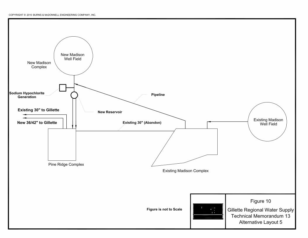
Alternative 5 Refer to Figures 5 and 10 for the layout of Alternative 5. In Alternative 5 the existing Madison well water would be pumped to the new Madison well field/on-site hypochlorite generation facilities. The new and existing Madison well water would be combined and pumped to the Pine Ridge Facilities. Alternative 5 includes one on-site sodium hypochlorite system located at the new Madison well field for disinfection of both water supplies at the new Madison facilities. Both water supplies would achieve the required chlorine contact time in a new reservoir near the on-site chlorine generation facilities and in the pipeline from the new Madison Complex to the Pine Ridge Facilities. The advantages of Alternative 5 include the following:
• One sodium hypochlorite system needs to be maintained. • Less expensive than two on-site sodium hypochlorite system. • Simple chemical feed system.


Technical Memorandum #13 Subject: Evaluation of Disinfection Alternatives July 20, 2010 Page 13 of 14
• Allows for disinfection contact time through the pipeline from the New Madison well field to the Pine Ridge Facilities.
The disadvantages of Alternative 5 include the following:
• Does not allow for disinfection contact time through the existing Madison reservoirs and pipeline to the new Madison well field.
• A reservoir is required near the on-site chlorine generation facilities or an oversized pipeline as discussed in Technical Memorandum 6 is required to achieve the chlorine contact time for the new and existing Madison well water that is not achieved in the pipeline to the Pipe Ridge Facilities.
• The land profile between existing Madison well field to the new Madison well field is rough terrain for the construction of a new pipeline.
CONSTRUCTION PHASING
Up to this point in the Technical Memorandum, the discussion has been on the ultimate capacity of the disinfection facility. A phased construction approach corresponding to the construction of new wells is recommended for design of the sodium hypochlorite storage and feed system. However, it is recommended that the building be sized for the total system capacity (40.2 MGD) at a dosage of 5 mg/L.
Phase 1 During initial construction only five (5) new Madison wells will be constructed. During Phase 1, yard piping, civil construction, and the building will be constructed for the total flow rate (40.2 MGD) and dosage (5 mg/L) as discussed in the alternatives. Within the building, the brine storage tank and sodium hypochlorite storage tanks will be designed for the total system capacity (40.2 MGD). The generator and dosage pumps will be sized for the five (5) new Madison wells. During this period, the existing gas chlorine facility will be used for the existing Madison wells. Table 9 has the design criteria and component sizing for Phase 1 of construction.

Technical Memorandum #13 Subject: Evaluation of Disinfection Alternatives July 20, 2010 Page 14 of 14
Table 9. Design Criteria for Phase 1.
Component Design
Generator Size
One (1) system Phase 1 Flow: 10 MGD Dosage: 5 mg/L Generator Size: 500 lbs/day
Brine Storage
Two (2) FRP Tanks (>8,200 gallons) Total Flow: 40.2 MGD Dosage: 5 mg/L 30 Days
Sodium Hypochlorite Storage
2 FRP Tanks (>25,200 gallons each) 2 Days Total Flow: 40.2 MGD Dosage: 5 mg/L Capable of storing 12.5% bulk delivery
Chemical Metering Pumps 0.5 mg/L at 0.13 MGD 5 mg/L at 10 MGD No turndown <20% of feed range.
Phase 2 Once the existing Madison gas chlorine system is decommissioned the on-site sodium hypochlorite system will be used for the disinfection of the existing Madison wells along with the five (5) new Madison wells for a total flow rate of 21.2 MGD. One additional 500 lb/day sodium hypochlorite generation system skid would used to produce the required amount of sodium hypochlorite. Additional chemical pumps would be added to the system for a flow rate of 21.2 MGD at a dosage of 5 mg/L. No additional storage would be required since it was sized for the total capacity in Phase 1.
Phase 3 Once the remaining new Madison wells are completed, the disinfection system will need to be capable of a total flow rate of 40.2 MGD at a dosage of 5 mg/L. An additional 700 lb/day generation system skid would used to produce the required amount of sodium hypochlorite. Additional chemical pumps would be added to the system for a flow rate of 40.2 MGD at a dosage of 5 mg/L. No additional storage would be required since it was sized for the total capacity in Phase 1.
CONCLUSION
Burns & McDonnell recommends Alternative 4 as the most practical alternative for the onsite sodium hypochlorite system with phasing as discussed previously. Alternative 4 has one onsite sodium hypochlorite system and one dosage point reducing maintenance associated with multiple systems. Refer to Technical Memorandum #6 for additional information on the disinfection contact time requirements and alternatives.