git sysml parametrics work [email protected] presenter [email protected]...
TRANSCRIPT
GIT SysML Parametrics [email protected]
GIT Product & System Lifecycle Management (PSLM) Centerwww.pslm.gatech.edu
Presentation toOMG Systems Engineering
Domain-Specific Interest Group (SE DSIG)
September 13, 2005Atlanta
v2
2Copyright © 2005
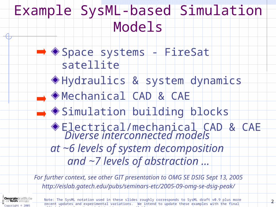
Example SysML-based Simulation Models
Space systems - FireSat satelliteHydraulics & system dynamicsMechanical CAD & CAESimulation building blocksElectrical/mechanical CAD & CAE
Note: The SysML notation used in these slides roughly corresponds to SysML draft v0.9 plus more recent updates and experimental variations. We intend to update these examples with the final official notation when v1.0 that becomes available.
Diverse interconnected models at ~6 levels of system decomposition
and ~7 levels of abstraction ...
For further context, see other GIT presentation to OMG SE DSIG Sept 13, 2005http://eislab.gatech.edu/pubs/seminars-etc/2005-09-omg-se-dsig-peak/
3Copyright © 2005
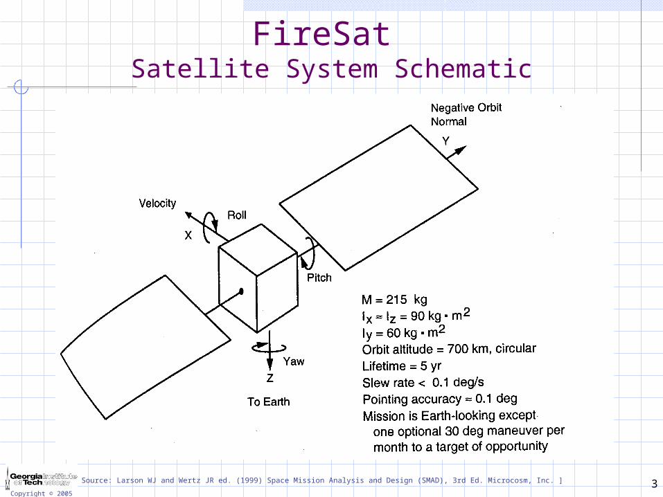
FireSat Satellite System Schematic
Source: Larson WJ and Wertz JR ed. (1999) Space Mission Analysis and Design (SMAD), 3rd Ed. Microcosm, Inc. ]
4Copyright © 2005
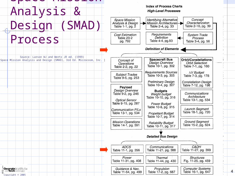
Space Mission Analysis & Design (SMAD) Process
Source: Larson WJ and Wertz JR ed. (1999) Space Mission Analysis and Design (SMAD), 3rd Ed. Microcosm, Inc. ]
5
sc orbit
sc slew
: ADC System
adc ss
sc mass properties
: Structures Sys
structures ss
…: Guid. & Navig.
Sys.
guidance & navigation ss…
: TT&C Sys
tt&c ss
: C&DH Sys.
c&dh ss
: Power System
power ss
: Thermal Sys.
thermal ss
mass
power
…
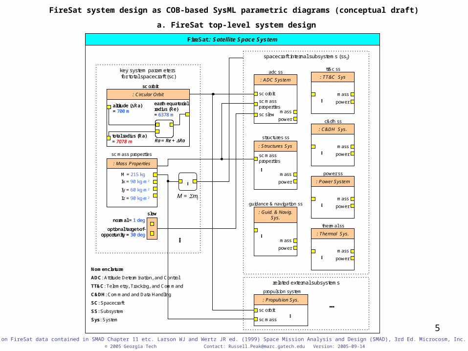
spacecraft internal subsystems (ssi)
key system parameters for total spacecraft (sc)
M = mi
…
…
FireSat : Satellite Space System
…
: Propulsion Sys.
sc orbit
sc mass
related external subsystems
…
Nomenclature
ADC: Attitude Determination, and Control
TT&C: Telemetry, Tracking, and Command
C&DH: Command and Data Handling
SC: Spacecraft
SS: Subsystem
Sys: System
: Mass Properties
sc mass properties
M = 215 kg
Ix = 90 kg-m2
Iy = 60 kg-m2
Iz = 90 kg-m2
slew
normal = 1 deg
optional target-of-opportunity = 30 deg
slew
normal = 1 deg
optional target-of-opportunity = 30 deg
propulsion system
mass
power
…mass
power
…
mass
power
…
sc mass properties
sc orbit
: Circular Orbit
altitude (Ra) = 700 m
total radius (Ra) = 7078 m
earth equatorial radius (Re) = 6378 m
Ra = Re + Ra
sc orbit
: Circular Orbit
altitude (Ra) = 700 m
total radius (Ra) = 7078 m
earth equatorial radius (Re) = 6378 m
Ra = Re + Ra
mass
power
mass
power
mass
power
FireSat system design as COB-based SysML parametric diagrams (conceptual draft)
a. FireSat top-level system design
© 2005 Georgia Tech Contact: [email protected] Version: 2005-09-14
Based on FireSat data contained in SMAD Chapter 11 etc. Larson WJ and Wertz JR ed. (1999) Space Mission Analysis and Design (SMAD), 3rd Ed. Microcosm, Inc. ]
6
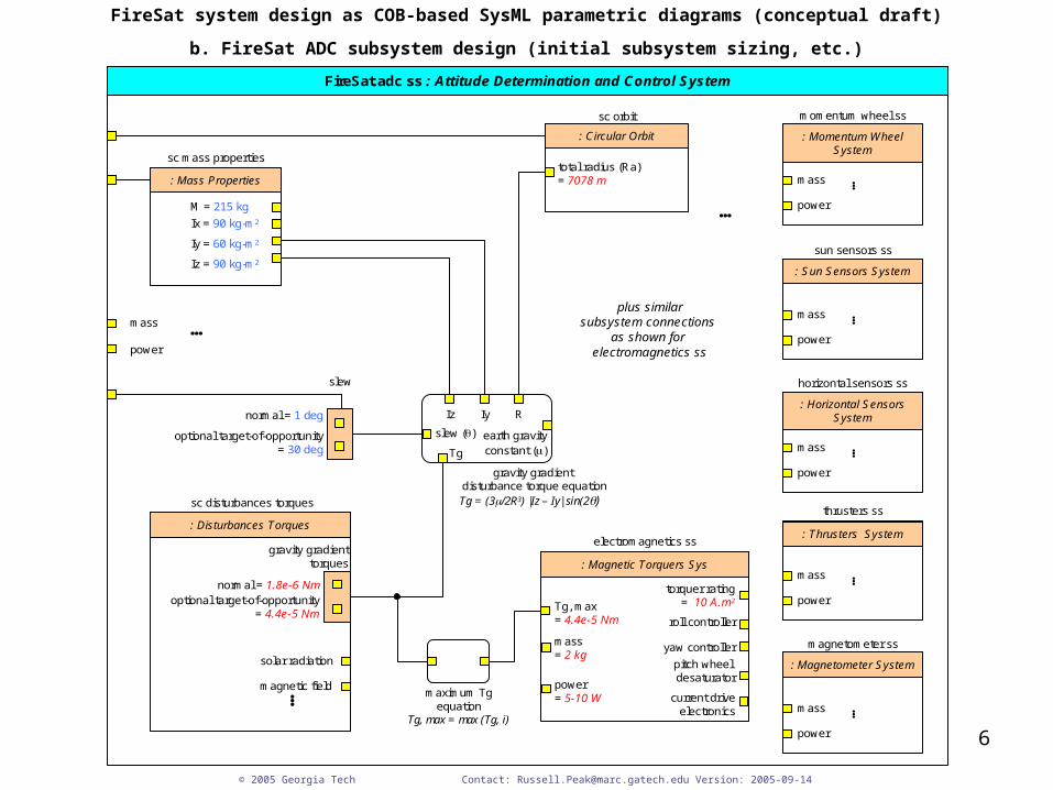
FireSat system design as COB-based SysML parametric diagrams (conceptual draft)
b. FireSat ADC subsystem design (initial subsystem sizing, etc.)
© 2005 Georgia Tech Contact: [email protected] Version: 2005-09-14
: Mass Properties
sc mass properties
M = 215 kg
: Magnetic Torquers Sys
electromagnetics ss
torquer rating= 10 A.m2
roll controller
: Momentum WheelSystem
momentum wheel ss
mass
power…
FireSat.adc ss : Attitude Determination and Control System
Ix = 90 kg-m2
Iy = 60 kg-m2
Iz = 90 kg-m2
: Disturbances Torques
sc disturbances torques
normal = 1.8e-6 Nmoptional target-of-opportunity
= 4.4e-5 Nm
solar radiation
magnetic field…
Iz Iy R
slew ()
Tg
earth gravityconstant ()
Tg, max= 4.4e-5 Nm
mass = 2 kg
power = 5-10 W
yaw controller
pitch wheel desaturator
Tg, max = max (Tg, i)
: Sun Sensors System
sun sensors ss
mass
power
…
: Horizontal SensorsSystem
horizontal sensors ss
mass
power
…
: Thrusters System
thrusters ss
mass
power
…
: Magnetometer System
magnetometer ss
mass
power
…
current driveelectronics
gravity gradient disturbance torque equation
…
plus similarsubsystem connections
as shown for electromagnetics ss
gravity gradienttorques
Tg = (3/2R3) |Iz – Iy| sin(2)
sc orbit
: Circular Orbit
total radius (Ra) = 7078 m
slew
normal = 1 deg
optional target-of-opportunity= 30 deg
maximum Tgequation
mass
power
…
7
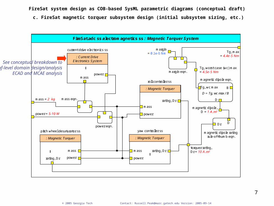
FireSat system design as COB-based SysML parametric diagrams (conceptual draft)
c. FireSat magnetic torquer subsystem design (initial subsystem sizing, etc.)
© 2005 Georgia Tech Contact: [email protected] Version: 2005-09-14
FireSat.adc ss.electromagnetics ss : Magnetic Torquer System
D = Tg, wc max / B
Tg, max= 4.4e-5 Nm
mass = 2 kg
power = 5-10 W
margin= 0.1e-5 Nm
magnetic dipole rating rule-of-thumb eqn.: Magnetic Torquer
pitch wheel desaturator ss
mass
power
…
: Magnetic Torquer
yaw controller ss
mass
power
…
: Magnetic Torquer
roll controller ss
mass
power
rating, Dr
: Current Drive Electronics System
current drive electronics ss
masspower
…
Tg, worst case (wc) max= 4.5e-5 Nm
B
DDr
Tg, wc max
torquer rating, Dr = 10 A.m2rating, Dr
rating, Dr
power eqn.
mass eqn. D
margin eqn.
magnetic dipole eqn.
magnetic dipole,D = 1 A.m2
See conceptual breakdown to leaf-level domain design/analysis
ECAD and MCAE analysis
8
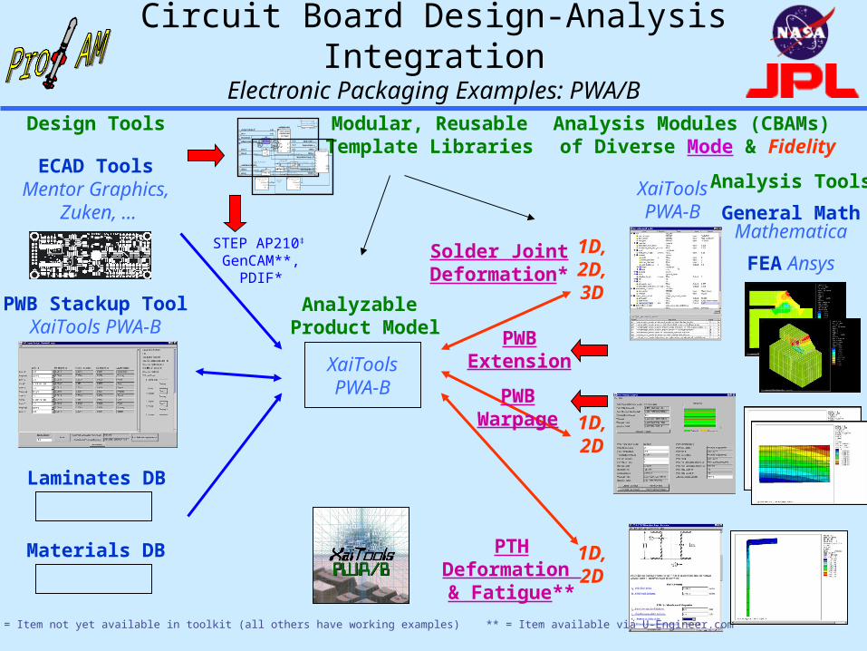
Circuit Board Design-Analysis IntegrationElectronic Packaging Examples: PWA/B
Analysis Modules (CBAMs) of Diverse Mode & Fidelity
Design Tools
Laminates DB
FEA Ansys
General MathMathematica
Analyzable Product Model
XaiToolsPWA-B
XaiToolsPWA-B
Solder JointDeformation*
PTHDeformation & Fatigue**
1D,2D
1D,2D,3D
Modular, ReusableTemplate Libraries
ECAD Tools Mentor Graphics,
Zuken, …
temperature change,T
material model
temperature, T
reference temperature, To
cte,
youngs modulus, E
force, F
area, A stress,
undeformed length, Lo
strain,
total elongation,L
length, L
start, x1
end, x2
mv6
mv5
smv1
mv1mv4
E
One D LinearElastic Model(no shear)
T
e
t
thermal strain, t
elastic strain, e
mv3
mv2
x
FF
E, A,
LLo
T, ,
yL
r1
12 xxL
r2
oLLL
r4
A
F
sr1
oTTT
r3L
L
m a t e r i a l
e f f e c t i v e l e n g t h , L e f f
d e f o r m a t i o n m o d e l
l i n e a r e l a s t i c m o d e l
L o
T o r s i o n a l R o d
G
J
r
2
1
s h e a r m o d u l u s , G
c r o s s s e c t i o n :e f f e c t i v e r i n g p o l a r m o m e n t o f i n e r t i a , J
a l 1
a l 3
a l 2 a
l i n k a g e
m o d e : s h a f t t o r s i o n
c o n d i t i o n r e a c t i o n
t s 1
A
S l e e v e 1
A t s 2
d s 2
d s 1
S l e e v e 2
L
S h a f t
L e f f
s
T
o u t e r r a d i u s , r o a l 2 b
s t r e s s m o s m o d e l
a l l o w a b l e s t r e s s
t w i s t m o s m o d e l
M a r g i n o f S a f e t y( > c a s e )
a l l o w a b l e
a c t u a l
M S
M a r g i n o f S a f e t y( > c a s e )
a l l o w a b l e
a c t u a l
M S
a l l o w a b l et w i s t Analysis Tools
PWBExtension
1D,2D
Materials DB
PWB Stackup ToolXaiTools PWA-B
STEP AP210‡
GenCAM**,PDIF*
‡ AP210 WD48 * = Item not yet available in toolkit (all others have working examples) ** = Item available via U-Engineer.com
PWBWarpage
9
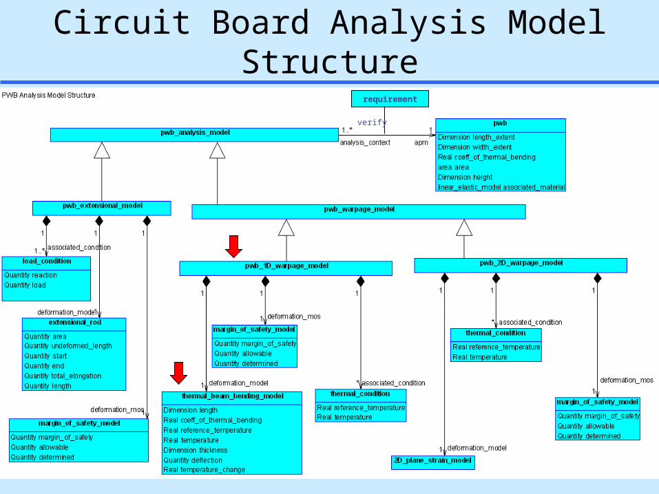
Circuit Board Analysis Model Structurerequirement
verify
10
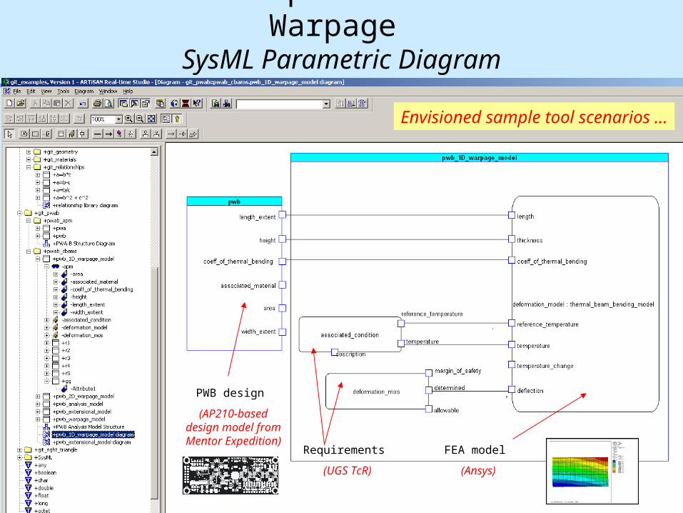
Simulation Template: Circuit Board Warpage SysML Parametric Diagram
PWB design
(AP210-baseddesign model from Mentor Expedition)
FEA model
(Ansys)
Requirements
(UGS TcR)
Envisioned sample tool scenarios ...
11
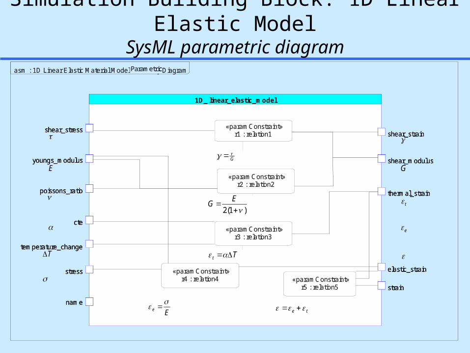
Simulation Building Block: 1D Linear Elastic ModelSysML parametric diagram
1D_ linear_elastic_model
«paramConstraint»r1 : relation1
«paramConstraint»r2 : relation2
«paramConstraint»r3 : relation3
«paramConstraint»r4 : relation4 «paramConstraint»
r5 : relation5
elastic_strain
temperature_change
youngs_modulus
stress
cte
poissons_ratio thermal_strain
strain
shear_modulus
shear_stressshear_strain
name
E
T
G
t
e
G
)1(2
EG
Tt
Ee
te
asm : 1D Linear Elastic Material Model Assembly DiagramParametricParametric
12Copyright © 2005
Contents
Space systems - FireSat satelliteHydraulics & system dynamicsMechanical CAD & CAESimulation building blocksElectrical/mechanical CAD & CAE
Modeling Hydraulic Systems Behavior Using SysML
Presented to:Dr. Gary May & Dr. Chris Paredis
By:Arnaldo J. Colón-López
Universidad del Turabo, P.R.Mechanical Engineering
Fifth Year
SRL
August 3, 2005
14
SRL
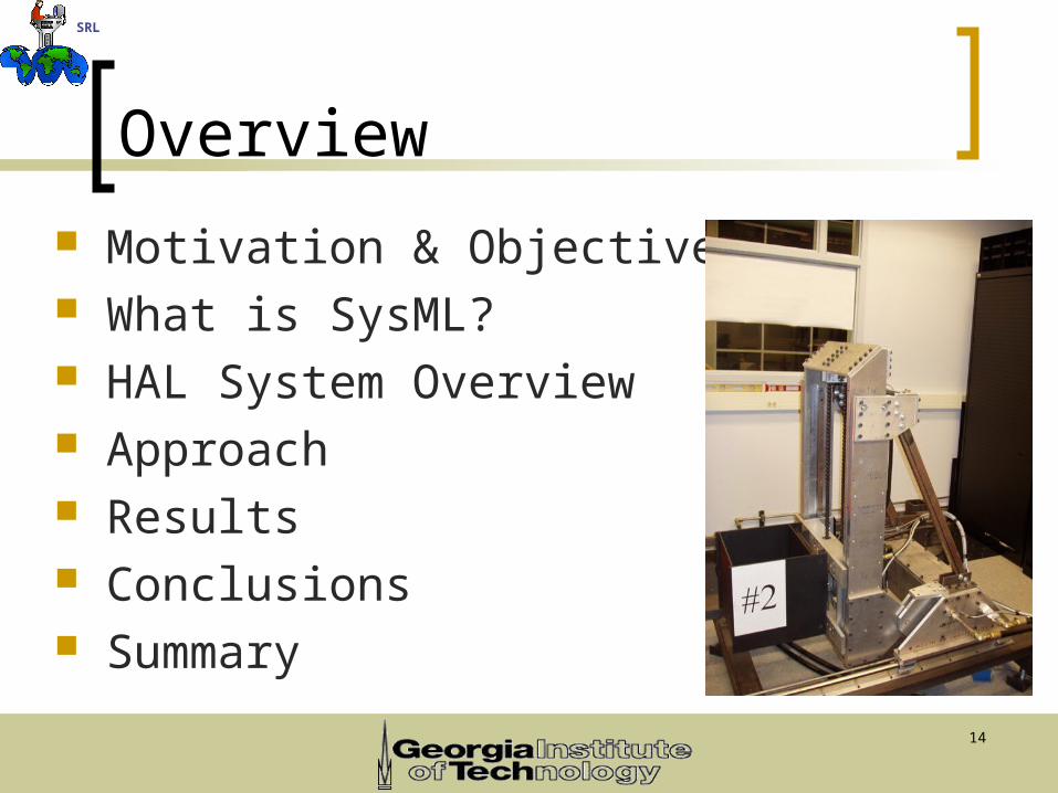
Overview
Motivation & Objectives What is SysML? HAL System Overview Approach Results Conclusions Summary
15
SRL
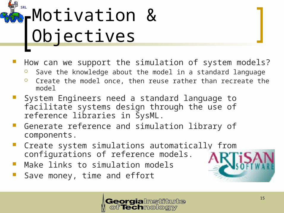
Motivation & Objectives How can we support the simulation of system models?
Save the knowledge about the model in a standard language Create the model once, then reuse rather than recreate the model
System Engineers need a standard language to facilitate systems design through the use of reference libraries in SysML.
Generate reference and simulation library of components. Create system simulations automatically from
configurations of reference models. Make links to simulation models Save money, time and effort
16
SRL
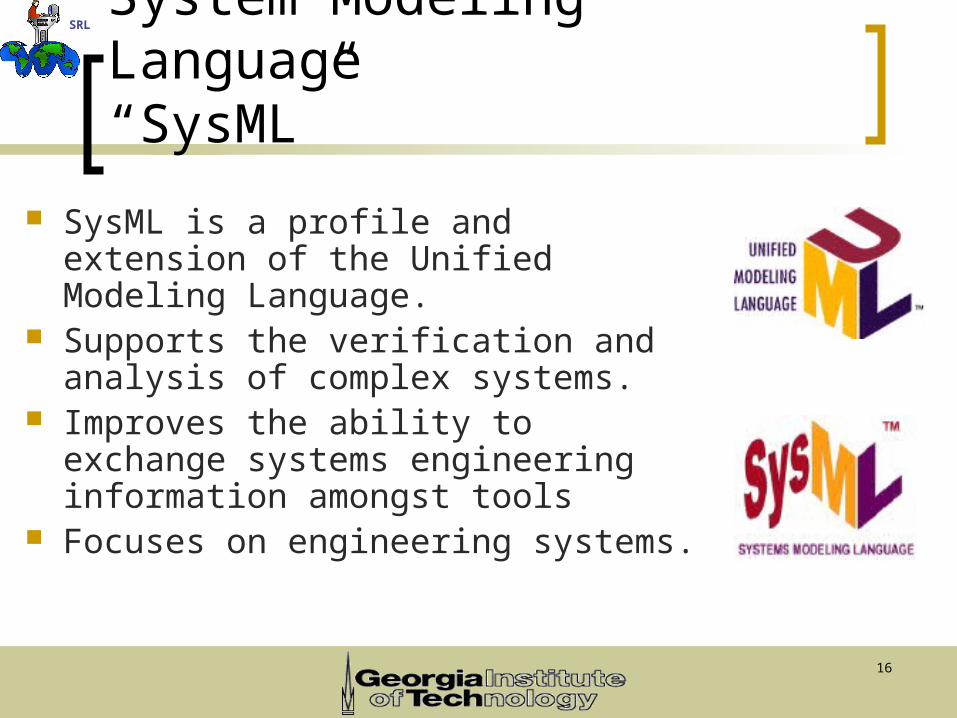
System Modeling Language“SysML”
SysML is a profile and extension of the Unified Modeling Language.
Supports the verification and analysis of complex systems.
Improves the ability to exchange systems engineering information amongst tools
Focuses on engineering systems.
17
SRL
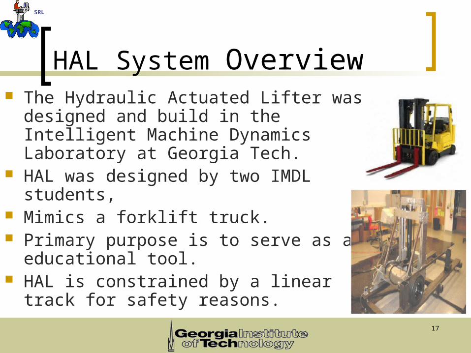
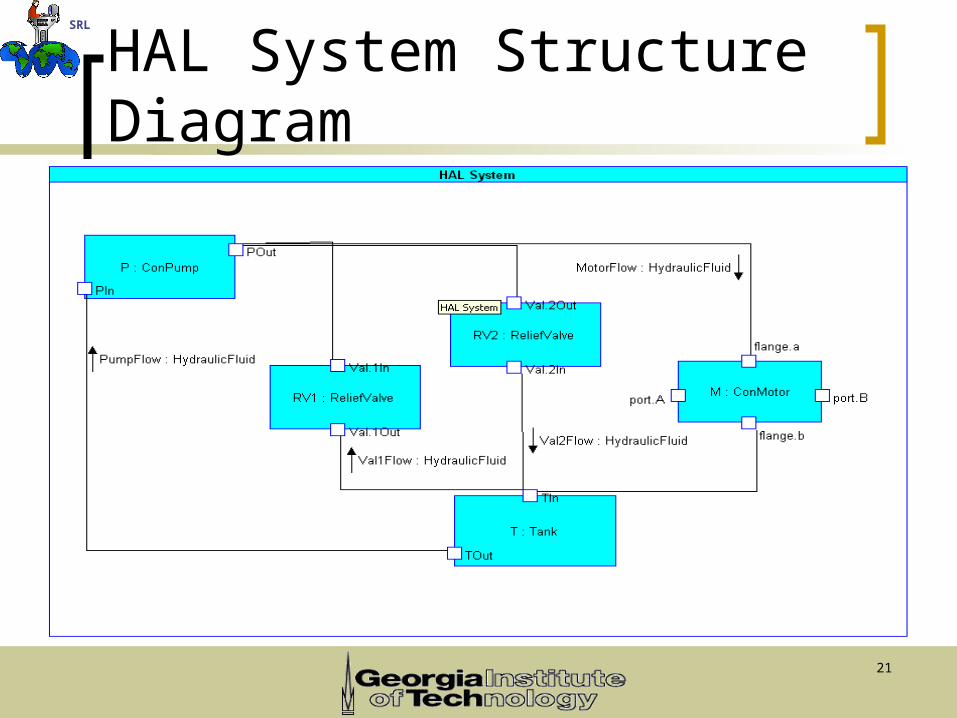
HAL System Overview The Hydraulic Actuated Lifter was
designed and build in the Intelligent Machine Dynamics Laboratory at Georgia Tech.
HAL was designed by two IMDL students, Mimics a forklift truck. Primary purpose is to serve as an
educational tool. HAL is constrained by a linear track for
safety reasons.
18
SRL
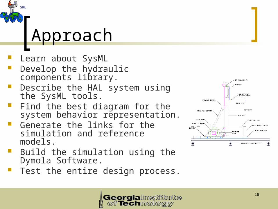
Approach Learn about SysML Develop the hydraulic components
library. Describe the HAL system using the
SysML tools. Find the best diagram for the system
behavior representation. Generate the links for the simulation
and reference models. Build the simulation using the Dymola
Software. Test the entire design process.
19
SRL
Results
20
SRL
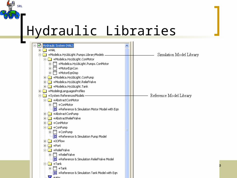
Hydraulic Libraries
21
SRL
HAL System Structure Diagram
22
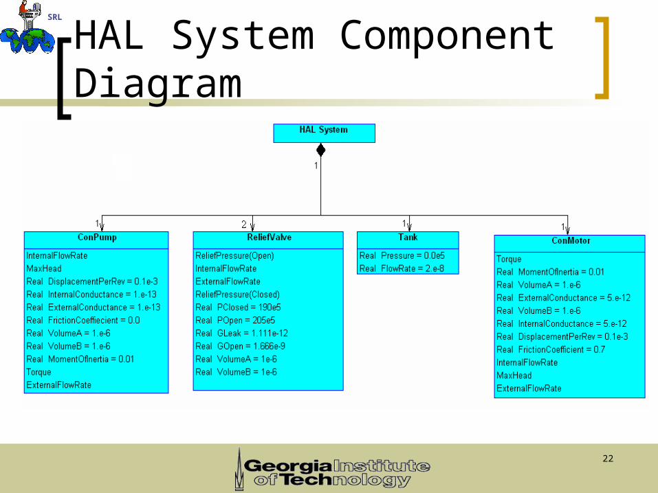
SRL
HAL System Component Diagram
23
SRL
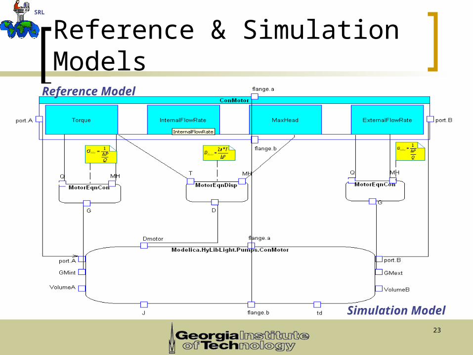
Reference & Simulation Models
Reference Model
Simulation Model
24
SRL
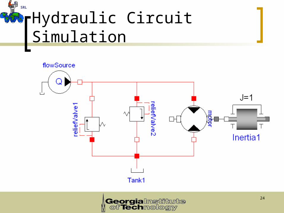
Hydraulic Circuit Simulation
25
SRL
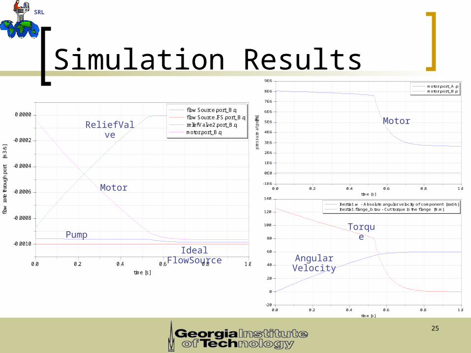
Simulation Results
0.0 0.2 0.4 0.6 0.8 1.0
-0.0010
-0.0008
-0.0006
-0.0004
-0.0002
0.0000
flow
rat
e th
roug
h po
rt
[m3/
s]
time [s]
f low Source.port_B.qf low Source.IFS.port_B.qreliefValve2.port_B.qmotor.port_B.q
0.0 0.2 0.4 0.6 0.8 1.0-1E6
0E0
1E6
2E6
3E6
4E6
5E6
6E6
7E6
8E6
9E6
pre
ssure
at port
[P
a]
time [s]
motor.port_A.pmotor.port_B.p
0.0 0.2 0.4 0.6 0.8 1.0-20
0
20
40
60
80
100
120
140
time [s]
Inertia1.w - Absolute angular velocity of component [rad/s]Inertia1.f lange_b.tau - Cut torque in the f lange [N.m]
Motor
Pump
ReliefValve
Ideal FlowSource
Motor
Torque
Angular Velocity
26
SRL
Conclusions SysML is a good language for defining
reference models. SysML defines the relation between the
reference and simulation models once Reuse the reference model often Saves time & resources.
27
SRL
Summary SysML is a profile and extension of Unified
Modeling Language. SysML was used to provide a standard
modeling language for systems engineering to analyze the HAL System.
Main SysML Diagrams are: Parametric, Class and Structure diagrams.
Artisan Real-Time Studio with SysML supports the representation of system behavior.
28
SRL
Acknowledgements Dr. Gary May
SURE Program Director Dr. Chris Paredis
My SURE Program Advisor Dr. Bruce Powel Douglas Manas Bajaj
Ph.D Student Sai Zeng
Research Scientist @ IBM Cornelius Ejimofor
My SURE Program Mentor & Ph.D Student Cleon Davis –
SURE Program Coordinator 2005 SURE Interns
29Copyright © 2005
ContentsSpace systems - FireSat satelliteHydraulics & system dynamicsMechanical CAD & CAESimulation building blocksElectrical/mechanical CAD & CAE
For more examples, see presentation & webcast archive available at:http://eislab.gatech.edu/pubs/conferences/2005-pde-peak/
For simulation template architecture & methodology, see:http://eislab.gatech.edu/pubs/seminars-etc/2005-cpda-dsfw-peak/
Diverse interconnected models at ~6 levels of system decomposition
and ~7 levels of abstraction ...