gk021 manual cover - elenco electronics · travelogue with mini beest cooperation/theo jansen media...
TRANSCRIPT
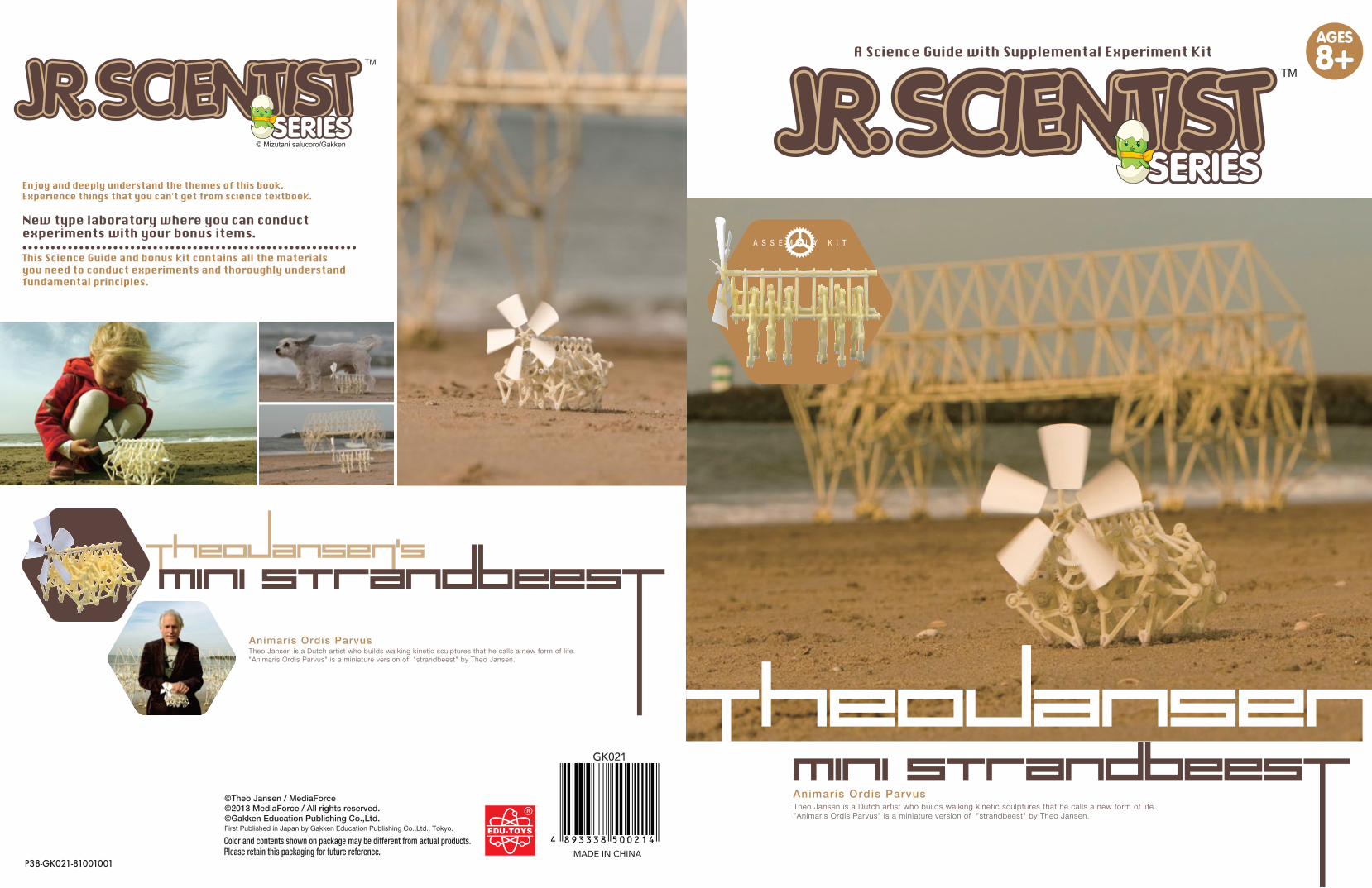
P38-GK021-81001001
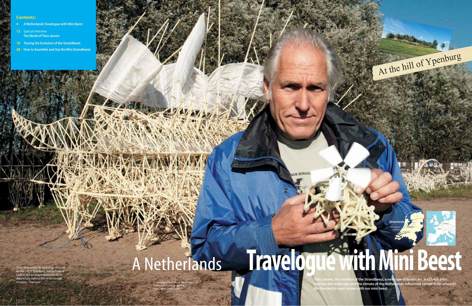
Travelogue with Mini BeestCooperation/Theo Jansen Media Force Ltd.Photograph/Loek van der KlisText/Gakken Editor Team
Theo Jansen, the inventor of the Strandbeest, a new type of kinetic art, is a Dutch artist. How has the landscape and the climate of the Netherlands in�uenced Jansen in his artwork? We traveled to meet Jansen with our mini beest.
Theo Jansen has his workshop situated on the hill of Ypenburg, just outside of Delft in the southern Netherlands. In the picture, behind him is his newest creation, "Siamesis".
Contents:4 A Netherlands Travelogue with Mini Beest
12 Special Interview The World of Theo Jansen
18 Tracing the Evolution of the Strandbeest
28 How to Assemble and Use the Mini Strandbeest
At the hill of Ypenburg
1 2
Netherlands
Scheveningen Amsterdam
Germany
France
RotterdamYpenburg
A Netherlands
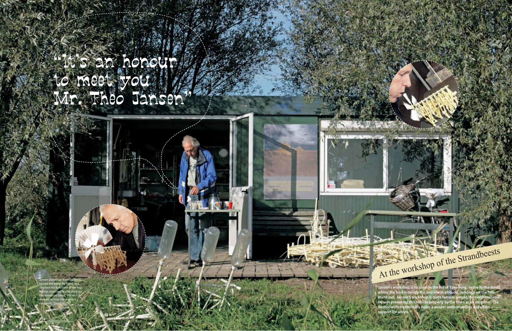
Jansen picked up the mini beest, turned the wings by hand, and checked the functions of the legs. He was absorbed in checking out this miniature beest. We were so relieved to hear the master's comment, "Good job!".
3 4
At the workshop of the Strandbeests
Jansen's workshop is located on the hill of Ypenburg. In the Netherlands, where the land is mostly �at and low in altitude, buildings on the hills stand out. Jansen's workshop is quite famous among the neighborhood. He was presented this hillside property by the town as an art grant. The Netherlands traditionally holds a deeper understanding and o�ers support for artists.
5 6
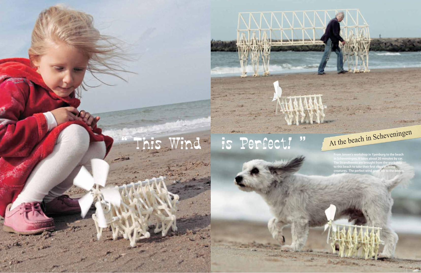
At the beach in Scheveningen
From Jansen's workshop in Ypenburg to the beach in Scheveningen, it takes about 20 minutes by car. The Strandbeests are brought from the workshop to this beach to take their �rst steps as living creatures. The perfect wind gives life to the beests.
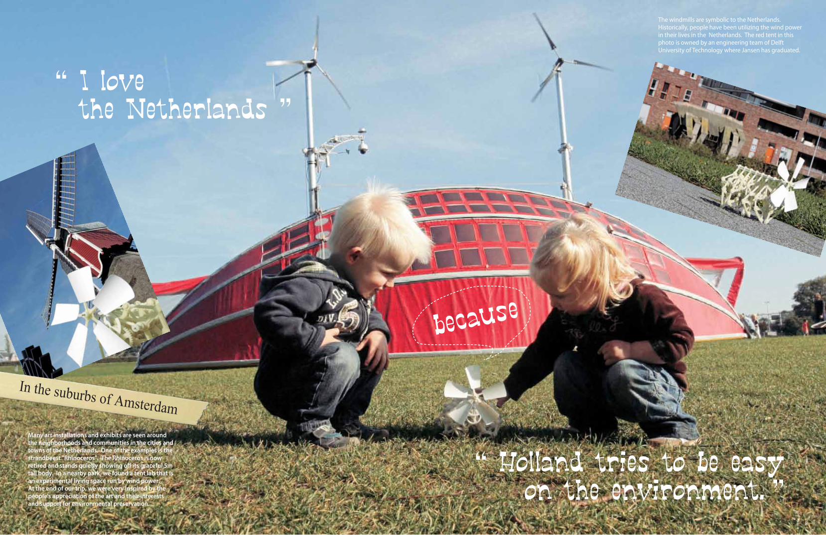
The windmills are symbolic to the Netherlands. Historically, people have been utilizing the wind power in their lives in the Netherlands. The red tent in this photo is owned by an engineering team of Delft University of Technology where Jansen has graduated.
7 8
In the suburbs of AmsterdamMany art installations and exhibits are seen around the neighborhoods and communities in the cities and towns of the Netherlands. One of the examples is the strandbeest "Rhinoceros". The Rhinoceros is now retired and stands quietly showing o� its graceful 5m tall body. In a nearby park, we found a tent lab that is an experimental living space run by wind power. At the end of our trip, we were very inspired by the people's appreciation of the art and their interests and support for environmental preservation.
How this creator made the beest.
9 10
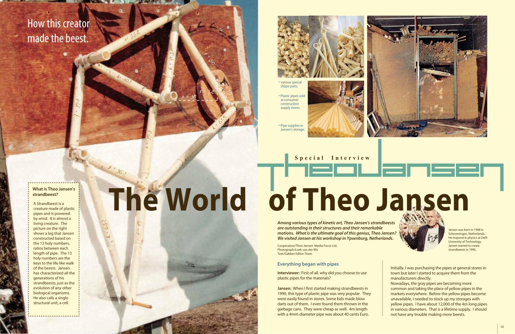
What is Theo Jansen's strandbeest?
→
S p e c i a l I n t e r v i e w
Everything began with pipes
The World of Theo JansenA Strandbeest is a creature made of plastic pipes and is powered by wind. It is almost a living creature. The picture on the right shows a leg that Jansen constructed based on the 13 holy numbers, ratios between each length of pipe. The 13 holy numbers are the keys to the life like walk of the beests. Jansen has characterized all the generations of his strandbeests, just as the evolution of any other biological organisms. He also calls a single structural unit, a cell.
various special shape parts.
Plastic pipes sold at consumer construction supply stores.
Pipe supplies in Jansen's storage.
Among various types of kinetic art, Theo Jansen's strandbeests are outstanding in their structures and their remarkable motions. What is the ultimate goal of this genius, Theo Jansen? We visited Jansen at his workshop in Ypsenburg, Netherlands.
Interviewer: First of all, why did you choose to use plastic pipes for the materials?
Jansen: When I �rst started making strandbeests in 1990, this type of plastic pipe was very popular. They were easily found in stores. Some kids made blow darts out of them. I even found them thrown in the garbage cans. They were cheap as well. 4m length with a 4mm diameter pipe was about 40 cents Euro.
Initially, I was purchasing the pipes at general stores in town but later I started to acquire them from the manufacturers directly. Nowadays, the gray pipes are becoming more common and taking the place of yellow pipes in the markets everywhere. Before the yellow pipes become unavailable, I needed to stock up my storages with yellow pipes. I have about 12,000 of the 4m long pipes in various diameters. That is a lifetime supply. I should not have any trouble making more beests.
Cooperation/Theo Jansen Media Force Ltd.Photograph/Loek van der KlisText/Gakken Editor Team
Jansen was born in 1948 in Scheveningen, Netherlands. He majored in physics at Delft University of Technology. Jansen started to create strandbeests in 1990.
11 12
Skeletal structures, nerves, and cells: Conditions inevitable for a life form....
Jansen: Some time in the last 20 years, I made my beests using wood and steel. Those beests are satisfying work for me but they are lacking something at the same time. I call those years my "a�air period" because my attention deviated from my beloved yellow pipes. The yellow pipes are the irreplaceable love of my life. I am just like Don Quixote. I am obsessed with the yellow pipes even though people laugh at me.
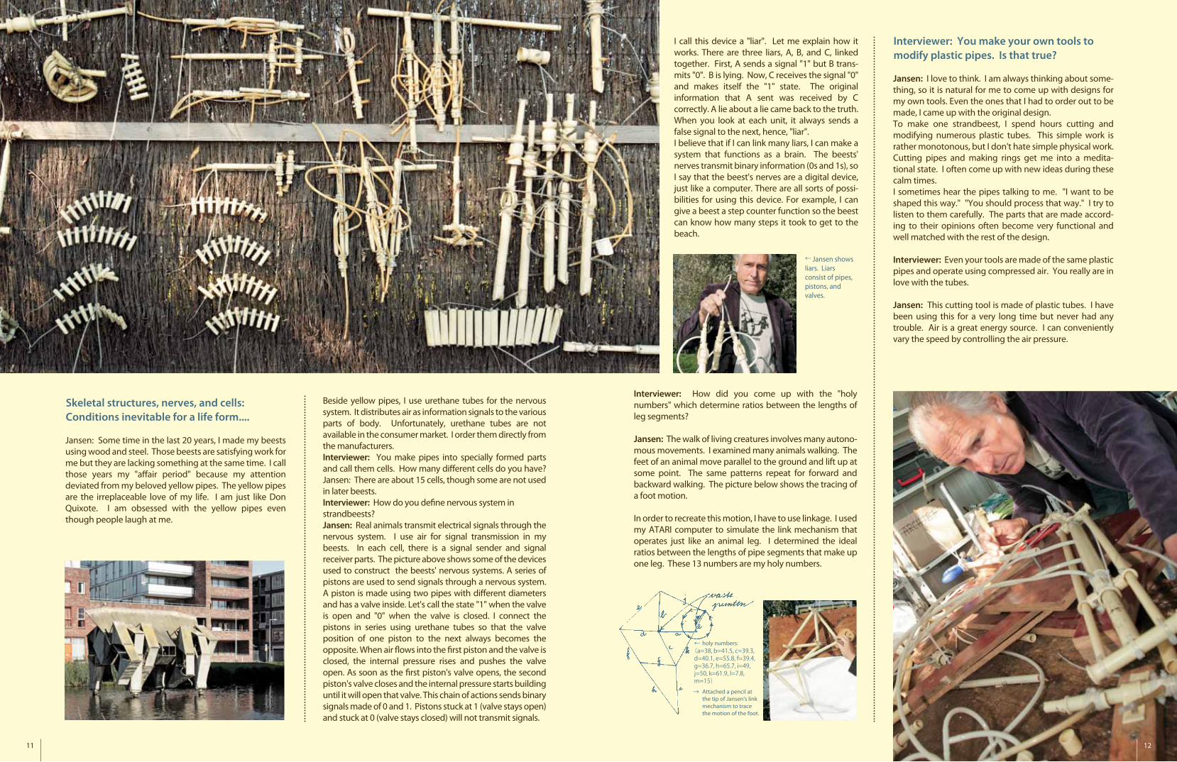
Beside yellow pipes, I use urethane tubes for the nervous system. It distributes air as information signals to the various parts of body. Unfortunately, urethane tubes are not available in the consumer market. I order them directly from the manufacturers. Interviewer: You make pipes into specially formed parts and call them cells. How many di�erent cells do you have?Jansen: There are about 15 cells, though some are not used in later beests.Interviewer: How do you de�ne nervous system in strandbeests?Jansen: Real animals transmit electrical signals through the nervous system. I use air for signal transmission in my beests. In each cell, there is a signal sender and signal receiver parts. The picture above shows some of the devices used to construct the beests' nervous systems. A series of pistons are used to send signals through a nervous system. A piston is made using two pipes with di�erent diameters and has a valve inside. Let's call the state "1" when the valve is open and "0" when the valve is closed. I connect the pistons in series using urethane tubes so that the valve position of one piston to the next always becomes the opposite. When air �ows into the �rst piston and the valve is closed, the internal pressure rises and pushes the valve open. As soon as the �rst piston's valve opens, the second piston's valve closes and the internal pressure starts building until it will open that valve. This chain of actions sends binary signals made of 0 and 1. Pistons stuck at 1 (valve stays open) and stuck at 0 (valve stays closed) will not transmit signals.
Interviewer: How did you come up with the "holy numbers" which determine ratios between the lengths of leg segments?
Jansen: The walk of living creatures involves many autono-mous movements. I examined many animals walking. The feet of an animal move parallel to the ground and lift up at some point. The same patterns repeat for forward and backward walking. The picture below shows the tracing of a foot motion.
In order to recreate this motion, I have to use linkage. I used my ATARI computer to simulate the link mechanism that operates just like an animal leg. I determined the ideal ratios between the lengths of pipe segments that make up one leg. These 13 numbers are my holy numbers.
←(a=38,
holy numbers:
Attached a pencil at the tip of Jansen's link mechanism to trace the motion of the foot.
b=41.5, c=39.3,d=40.1, e=55.8, f=39.4,g=36.7, h=65.7, i=49,j=50, k=61.9, l=7.8,m=15)
I call this device a "liar". Let me explain how it works. There are three liars, A, B, and C, linked together. First, A sends a signal "1" but B trans-mits "0". B is lying. Now, C receives the signal "0" and makes itself the "1" state. The original information that A sent was received by C correctly. A lie about a lie came back to the truth. When you look at each unit, it always sends a false signal to the next, hence, "liar". I believe that if I can link many liars, I can make a system that functions as a brain. The beests' nerves transmit binary information (0s and 1s), so I say that the beest's nerves are a digital device, just like a computer. There are all sorts of possi-bilities for using this device. For example, I can give a beest a step counter function so the beest can know how many steps it took to get to the beach.
Jansen shows liars. Liars consist of pipes, pistons, and valves.
Interviewer: You make your own tools to modify plastic pipes. Is that true?
Jansen: I love to think. I am always thinking about some-thing, so it is natural for me to come up with designs for my own tools. Even the ones that I had to order out to be made, I came up with the original design.To make one strandbeest, I spend hours cutting and modifying numerous plastic tubes. This simple work is rather monotonous, but I don't hate simple physical work. Cutting pipes and making rings get me into a medita-tional state. I often come up with new ideas during these calm times.I sometimes hear the pipes talking to me. "I want to be shaped this way." "You should process that way." I try to listen to them carefully. The parts that are made accord-ing to their opinions often become very functional and well matched with the rest of the design.
Interviewer: Even your tools are made of the same plastic pipes and operate using compressed air. You really are in love with the tubes.
Jansen: This cutting tool is made of plastic tubes. I have been using this for a very long time but never had any trouble. Air is a great energy source. I can conveniently vary the speed by controlling the air pressure.
13 14
Theory of Evolution
Interviewer: Why do you describe the history of the strandbeests as the theory of evolution?
Jansen: I was greatly in�uenced by Richard Dawkins' Sel�sh Gene in my 20's. I wanted to evolve my beests by expanding one idea into modi�ed and improved versions.
Interviewer: Have you researched any species and/or their evolutional process?
Jansen: No. On the contrary, I stayed away from modeling the evolutionary histories of any existing organisms. My focus has been always �nding necessary functions and abilities for the beests to adapt to the environment and survive. For example, the newer beest can anchor itself by hammering a peg into the sandy ground in order to keep its body from being blown away by gusts of wind. It also senses the tide coming in and moves toward dry land. I have often found that some of my beests resemble existing beach creatures or the evolutionary process is similar to that of natural organisms.
Interviewer: How are they going to continue evolving in the future?
Jansen: My ultimate goal is that the strandbeests stroll, eat, reproduce, and survive as a group on the beach without me. I need to improve their energy system: store air in the PET bottles and utilize it as needed. Liars need to be modi�ed to accommodate a more complex nervous system. I would like the beests to behave autonomously.
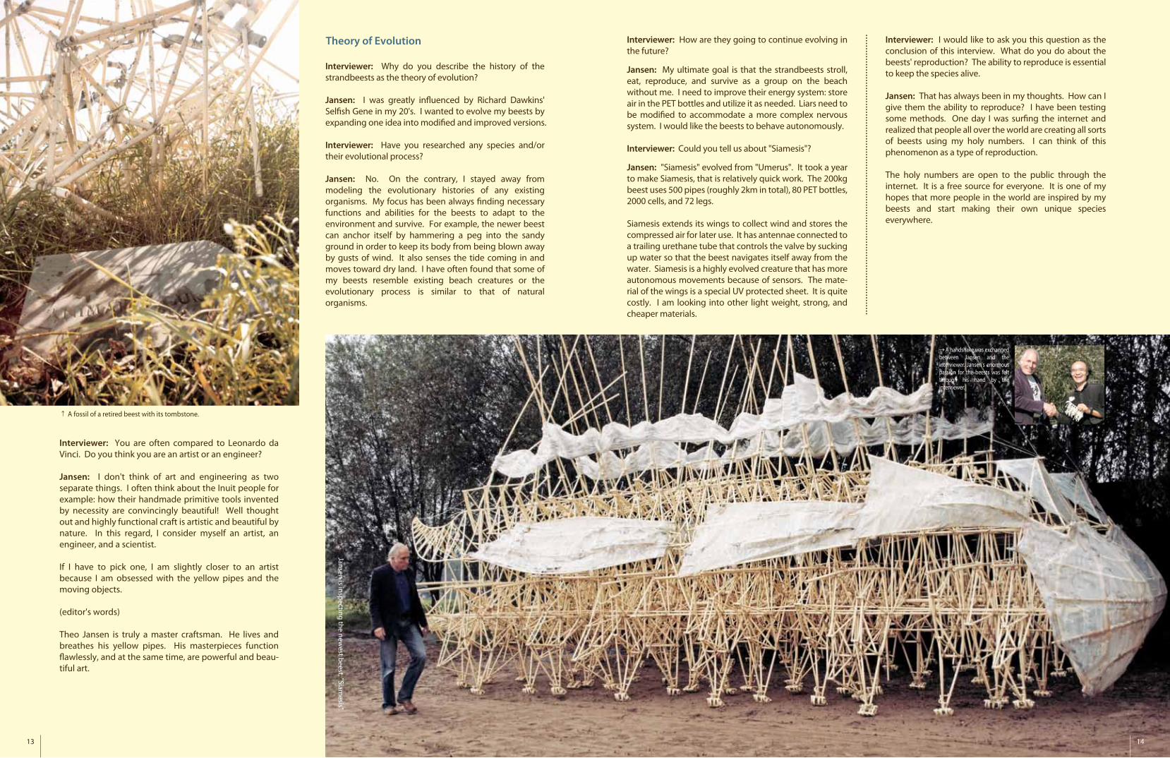
Interviewer: Could you tell us about "Siamesis"?
Jansen: "Siamesis" evolved from "Umerus". It took a year to make Siamesis, that is relatively quick work. The 200kg beest uses 500 pipes (roughly 2km in total), 80 PET bottles, 2000 cells, and 72 legs.
Siamesis extends its wings to collect wind and stores the compressed air for later use. It has antennae connected to a trailing urethane tube that controls the valve by sucking up water so that the beest navigates itself away from the water. Siamesis is a highly evolved creature that has more autonomous movements because of sensors. The mate-rial of the wings is a special UV protected sheet. It is quite costly. I am looking into other light weight, strong, and cheaper materials.
Interviewer: I would like to ask you this question as the conclusion of this interview. What do you do about the beests' reproduction? The ability to reproduce is essential to keep the species alive.
Jansen: That has always been in my thoughts. How can I give them the ability to reproduce? I have been testing some methods. One day I was sur�ng the internet and realized that people all over the world are creating all sorts of beests using my holy numbers. I can think of this phenomenon as a type of reproduction.
The holy numbers are open to the public through the internet. It is a free source for everyone. It is one of my hopes that more people in the world are inspired by my beests and start making their own unique species everywhere.
Interviewer: You are often compared to Leonardo da Vinci. Do you think you are an artist or an engineer?
Jansen: I don't think of art and engineering as two separate things. I often think about the Inuit people for example: how their handmade primitive tools invented by necessity are convincingly beautiful! Well thought out and highly functional craft is artistic and beautiful by nature. In this regard, I consider myself an artist, an engineer, and a scientist.
If I have to pick one, I am slightly closer to an artist because I am obsessed with the yellow pipes and the moving objects.
(editor's words)
Theo Jansen is truly a master craftsman. He lives and breathes his yellow pipes. His masterpieces function �awlessly, and at the same time, are powerful and beau-tiful art.
A fossil of a retired beest with its tombstone.
Jansen is inspecting the newest beest, "Siam
esis".
A handshake was exchanged between Jansen and the interviewer. Jansen's enormous passion for the beests was felt through his hand by the interviewer.
15 16
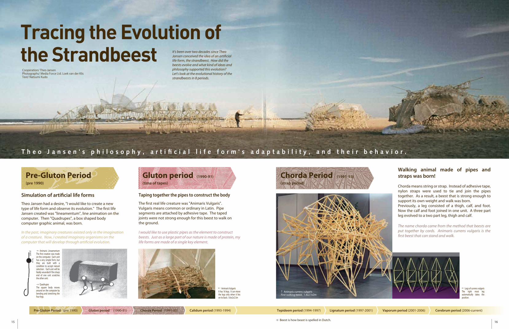
Pre-Gluton Period (pre 1990)
Gluton period (1990-91)
(time of tapes)
Chorda Period (1991-93)
(strap period)
T h e o J a n s e n ' s p h i l o s o p h y , a r t i � c i a l l i f e f o r m ' s a d a p t a b i l i t y , a n d t h e i r b e h a v i o r .
Tracing the Evolution of the StrandbeestCooperation/ Theo JansenPhotographs/ Media Force Ltd. Loek van der KlisText/ Natsumi Kudo
←
Pre-Gluton Period (pre 1990) Gluton period (1990-91) Chorda Period (1991-93) Calidum period (1993-1994) Lignatum period (1997-2001) Vaporum period (2001-2006) Cerebrum period (2006-current)Tepideem period (1994-1997)
Beest is how beast is spelled in Dutch.
It's been over two decades since Theo Jansen conceived the idea of an arti�cial life form, the strandbeest. How did the beests evolve and what kind of ideas and philosophy supported this evolution? Let's look at the evolutional history of the strandbeests in 8 periods.
Simulation of arti�cial life forms
Theo Jansen had a desire, "I would like to create a new type of life form and observe its evolution." The �rst life Jansen created was "lineamentum", line animation on the computer. Then "Quadrupes", a box shaped body computer graphic animal, was born.
In the past, imaginary creatures existed only in the imagination of a creature. Now, I created imaginary organisms on the computer that will develop through arti�cial evolution.
Walking animal made of pipes and straps was born!
Chorda means string or strap. Instead of adhesive tape, nylon straps were used to tie and join the pipes together. As a result, a beest that is strong enough to support its own weight and walk was born. Previously, a leg consisted of a thigh, calf, and foot. Now the calf and foot joined in one unit. A three part leg evolved to a two part leg, thigh and calf.
The name chorda came from the method that beests are put together by cords. Animaris currens vulgaris is the �rst beest that can stand and walk.
Taping together the pipes to construct the body
The �rst real life creature was "Animaris Vulgaris". Vulgaris means common or ordinary in Latin. Pipe segments are attached by adhesive tape. The taped joints were not strong enough for this beest to walk on the ground.
I would like to use plastic pipes as the element to construct beests. Just as a large part of our nature is made of protein, my life forms are made of a single key element.
Animaris Lineamentum The �rst creation was made on the computer. Each unit has a very simple form, but they are built with a condition to accept natural selection: Each unit will be fatally wounded if the sharp end of one unit scratches the other unit.
QuadrupesThe square body moves around on the computer by bending and stretching the four legs.
Animaris VulgarisIt has 16 legs. It can move the legs only when it lies on its back. 0.6x2x2.5m
Legs of currens vulgarisThe right most leg automatically takes the position.
Animaris currens vulgarisFirst walking beest. 1.4x2.1x2m
17 18
Calidum period 1993-1994 (heat period)
Pre-Gluton Period (pre 1990) Gluton period (1990-91) Chorda Period (1991-93) Calidum period (1993-1994) Lignatum period (1997-2001) Vaporum period (2001-2006) Cerebrum period (2006-current)Tepideem period (1994-1997)
Walk with �apping wings by the wind
In this period, beests had evolved remarkably. Animaris Currens Ventosa (shown in the picture) means animal running by the wind. It acquired large wings and walked by �apping its wings. A new creature activated by wind energy was born. The new development in the manufacturing process was that heat guns were used to bend or fuse the tubes. A variety of new parts were made by modifying the tubes by heat gun.
Animals that can utilize wind energy to live do not need to eat food. This type of creature can dominate sandy beaches where there is an abundance of wind but not very much nutrients. This is a tremendous advantage to the strandbeests since they do not need to compete with the other animals in the nature.
Animaris sabulosa adolescensIt has four wings. The legs are controlled by a speed changing device. 4.5x2m
Front view of animaris currens ventosa
Animaris currens ventosaWind caught by the wings on the back moves legs. 3.2x5.5x4m
←
(top) sketch of tail of animaris subulosa adolescens(bottom) concept sketch of speed control mechanism
19 20
Pre-Gluton Period (pre 1990) Gluton period (1990-91) Chorda Period (1991-93) Calidum period (1993-1994) Lignatum period (1997-2001) Vaporum period (2001-2006) Cerebrum period (2006-current)Tepideem period (1994-1997)
Tepideem period 1994-1997 (reduced heat period)
Reproduced from DNA of plastic pipes
Tepideem period means reduced heat time. Jansen considers this period as the reproduction period. Here, reproduction was not through mating and fertilization. It has done by copying the DNA and multiplying the same beests. Creatures sharing the same plastic parts (DNA) were produced. Animaris geneticus indicates the concept. Beests in a group started showing up on the beach.
Not ambiguous genetic data but real gene is transferred to the next generations. Naturally, beests' DNAs are not made of amino acids. Their gene is plastic pipes. (top left)
Animaris rigide properansIt has a propeller. It is capable to walk fast at beach. 14.6x2.5x2m(top right)Animaris propagare 0.7x1x1m
↑
Animaris geneticus ondulaEach leg was controlled by a special angled crank so that each leg moves slightly di�erently. The legs move like a wave in the ocean. 1.7x8.5x2
A group of animaris genetics. There are total of 357 exchangeable DNA (pipe) 1.5~1.8×2.5×2m
21 22
Pre-Gluton Period (pre 1990) Gluton period (1990-91) Chorda Period (1991-93) Calidum period (1993-1994) Lignatum period (1997-2001) Vaporum period (2001-2006) Cerebrum period (2006-current)Tepideem period (1994-1997)
Animaris rugosus peristhaltis Its back made of bent pipes waves.0.5x1.3x0.4m
Animaris vemiculusIt stores wind in 28 PET bottles.1.6x5x0.8m
Nerve cells made of combined plastic pipes and tubes.
Lignatum period 1997-2001(wood period)
Gigantic walking beests made of wood
This period named after Latin word lignum (wood). Beests made of plastic pipes cannot exceed certain body sizes and volumes due to the �exible nature of plastic. Jansen was attracted to wood and metal for the alternative resource to make the beests. He created an enormous beest, animaris rhinoceros transport. Its legs are made of hexagonally joined steel pallets. The rectangular body has 12 legs in total.
I needed to look into alternative materials in order to make gigan-tic beests. Wood and metal pallets made it possible to produce a new style of strandbeest.
Vaporum period 2001-2006 (wind period)
Move itself using stored wind in the bottles
Vaporum means vapor. Past beests all moved by naturally occurring wind, however, these newer beests use stored and compressed wind. They can. to a point, move themselves with their own wills. Jansen calls this new air system, muscles. Animaris vermiculus, shown below, has 28 muscles. Jansen modi�ed his de�nition of gene from the plastic pipes to the ratios between the lengths of pipe segments of each leg.
The characteristics of the beests' walking style depends on the lengths of the pipe segments of their legs, in other words, the speci�c distances between two joints. A new gene came out from the combination of three pipes of di�erent lengths.
Back side of animaris rhinoceros transport
Animaris rhinoceros transport walks by the wind from behind. 4.7x6x5m
23 24
Pre-Gluton Period (pre 1990) Gluton period (1990-91) Chorda Period (1991-93) Calidum period (1993-1994) Lignatum period (1997-2001) Vaporum period (2001-2006) Cerebrum period (2006-current)Tepideem period (1994-1997)
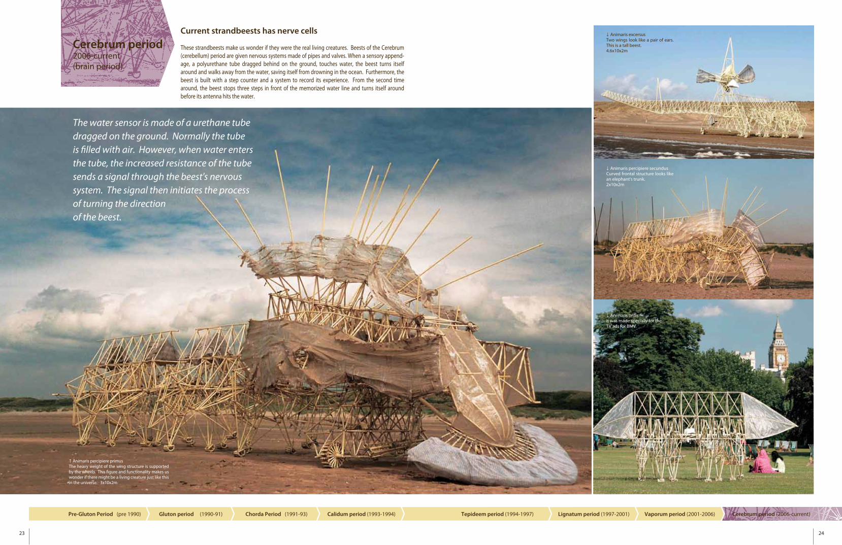
Animaris percipiere primusThe heavy weight of the wing structure is supported by the wheels. This �gure and functionality makes us wonder if there might be a living creature just like this in the universe. 3x10x2m
Cerebrum period 2006-current(brain period)
Current strandbeests has nerve cells
These strandbeests make us wonder if they were the real living creatures. Beests of the Cerebrum (cerebellum) period are given nervous systems made of pipes and valves. When a sensory append-age, a polyurethane tube dragged behind on the ground, touches water, the beest turns itself around and walks away from the water, saving itself from drowning in the ocean. Furthermore, the beest is built with a step counter and a system to record its experience. From the second time around, the beest stops three steps in front of the memorized water line and turns itself around before its antenna hits the water.
The water sensor is made of a urethane tube dragged on the ground. Normally the tube is �lled with air. However, when water enters the tube, the increased resistance of the tube sends a signal through the beest's nervous system. The signal then initiates the process of turning the direction of the beest.
Animaris excersusTwo wings look like a pair of ears. This is a tall beest.4.6x10x2m
Animaris percipiere secundusCurved frontal structure looks like an elephant's trunk.2x10x2m
Animaris ordisit was made specially for the TV ads for BMV.
25 26
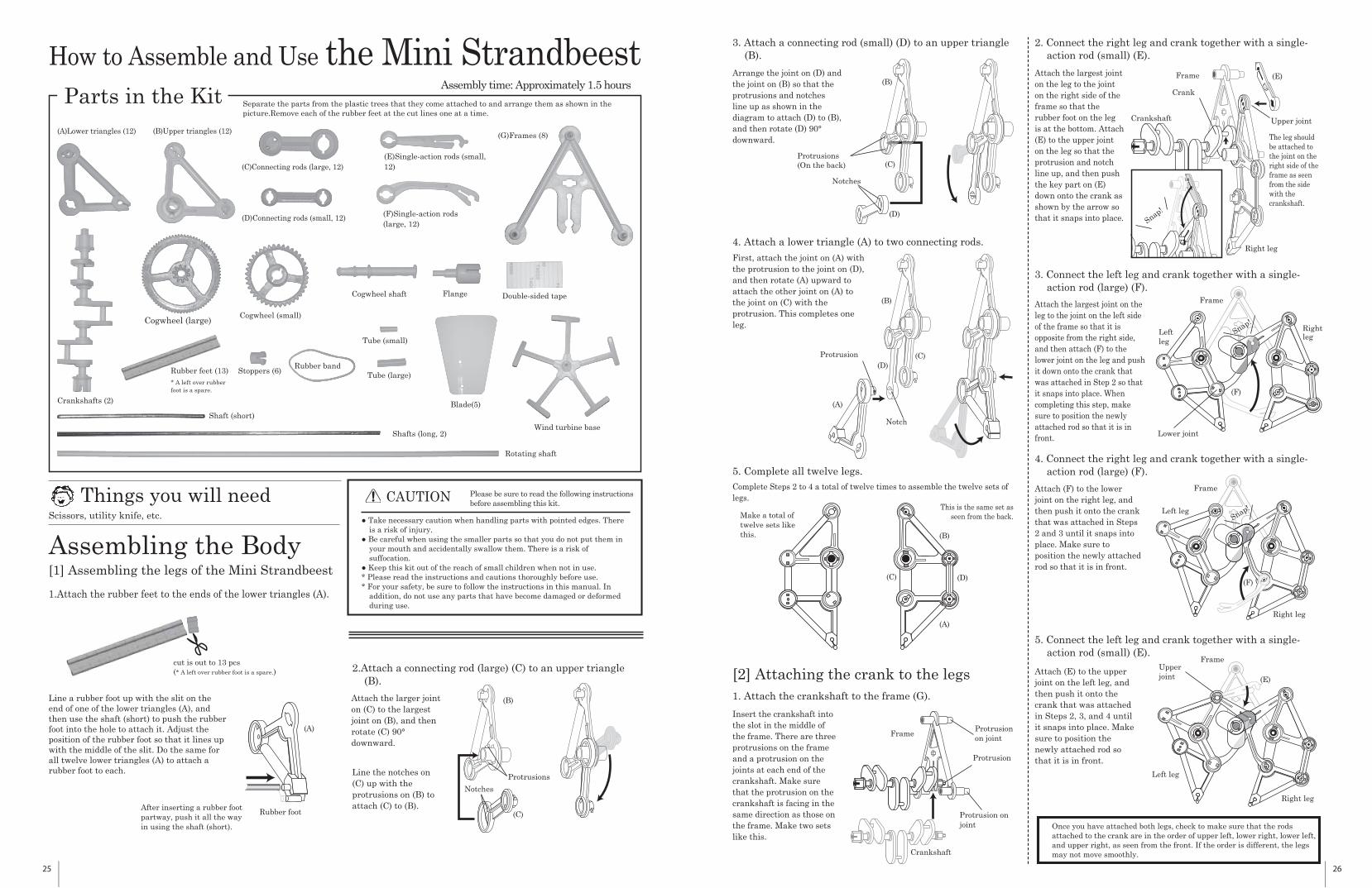
Things you will needScissors, utility knife, etc.
Parts in the Kit
How to Assemble and Use the Mini StrandbeestAssembly time: Approximately 1.5 hours
CAUTION Please be sure to read the following instructions before assembling this kit.
● Take necessary caution when handling parts with pointed edges. There is a risk of injury.
● Be careful when using the smaller parts so that you do not put them in your mouth and accidentally swallow them. There is a risk of suffocation.
● Keep this kit out of the reach of small children when not in use.* Please read the instructions and cautions thoroughly before use.* For your safety, be sure to follow the instructions in this manual. In
addition, do not use any parts that have become damaged or deformed during use.
(A)Lower triangles (12) (B)Upper triangles (12) (G)Frames (8)
Rubber feet (13) Stoppers (6)
Cogwheel (small)Cogwheel (large)
Cogwheel shaft Flange
Shaft (short)
Shafts (long, 2)Wind turbine base
Rotating shaft
Rubber band
Double-sided tape
Tube (small)
Tube (large)
Blade(5)
(C)Connecting rods (large, 12)
Crankshafts (2)
(D)Connecting rods (small, 12)
(E)Single-action rods (small, 12)
(F)Single-action rods (large, 12)
Assembling the Body[1] Assembling the legs of the Mini Strandbeest
1.Attach the rubber feet to the ends of the lower triangles (A).
2.Attach a connecting rod (large) (C) to an upper triangle (B).
(A)
(B)
(C)Rubber footAfter inserting a rubber foot
cut is out to 13 pcs(* A left over rubber foot is a spare.)
partway, push it all the way in using the shaft (short).
Notches
Protrusions
Line a rubber foot up with the slit on the end of one of the lower triangles (A), andthen use the shaft (short) to push the rubberfoot into the hole to attach it. Adjust theposition of the rubber foot so that it lines upwith the middle of the slit. Do the same forall twelve lower triangles (A) to attach arubber foot to each.
Attach the larger joint on (C) to the largest joint on (B), and then rotate (C) 90° downward.
Line the notches on (C) up with the protrusions on (B) to attach (C) to (B).
Separate the parts from the plastic trees that they come attached to and arrange them as shown in the picture.Remove each of the rubber feet at the cut lines one at a time.
* A left over rubber foot is a spare.
3. Attach a connecting rod (small) (D) to an upper triangle (B).
4. Attach a lower triangle (A) to two connecting rods.
5. Complete all twelve legs. Complete Steps 2 to 4 a total of twelve times to assemble the twelve sets of legs.
Make a total of twelve sets like this.
(A)
(B)
(C) (D)
(B)
(C)
(D)
Notches
Protrusions(On the back)
Notch
Protrusion
[2] Attaching the crank to the legs1. Attach the crankshaft to the frame (G).
Crankshaft
Protrusion on joint
Protrusion on joint
Protrusion
Arrange the joint on (D) and the joint on (B) so that the protrusions and notches line up as shown in the diagram to attach (D) to (B), and then rotate (D) 90° downward.
Insert the crankshaft into the slot in the middle of the frame. There are three protrusions on the frame and a protrusion on the joints at each end of the crankshaft. Make sure that the protrusion on the crankshaft is facing in the same direction as those on the frame. Make two sets like this.
2. Connect the right leg and crank together with a single-action rod (small) (E).
Crankshaft
Frame (E)
Crank
Snap!
The leg should be attached to the joint on the right side of the frame as seen from the side with the crankshaft.
Upper joint
Right legFirst, attach the joint on (A) with the protrusion to the joint on (D), and then rotate (A) upward to attach the other joint on (A) to the joint on (C) with the protrusion. This completes one leg.
Attach the largest joint on the leg to the joint on the right side of the frame so that the rubber foot on the leg is at the bottom. Attach (E) to the upper joint on the leg so that the protrusion and notch line up, and then push the key part on (E) down onto the crank as shown by the arrow so that it snaps into place.
Attach the largest joint on the leg to the joint on the left side of the frame so that it is opposite from the right side, and then attach (F) to the lower joint on the leg and push it down onto the crank that was attached in Step 2 so that it snaps into place. When completing this step, make sure to position the newly attached rod so that it is in front.
(F)
Lower joint
Snap!Left leg
Right leg
Frame
3. Connect the left leg and crank together with a single-action rod (large) (F).
4. Connect the right leg and crank together with a single-action rod (large) (F).
(F)
Left leg
Right leg
Frame
5. Connect the left leg and crank together with a single-action rod (small) (E).
Upper joint (E)
Attach (F) to the lower joint on the right leg, and then push it onto the crank that was attached in Steps 2 and 3 until it snaps into place. Make sure to position the newly attached rod so that it is in front.
Attach (E) to the upper joint on the left leg, and then push it onto the crank that was attached in Steps 2, 3, and 4 until it snaps into place. Make sure to position the newly attached rod so that it is in front.
Left leg
Right leg
Frame
Snap!
Frame
This is the same set as seen from the back.
(A)
(B)
(C) (D)
Once you have attached both legs, check to make sure that the rods attached to the crank are in the order of upper left, lower right, lower left, and upper right, as seen from the front. If the order is different, the legs may not move smoothly.
27 28
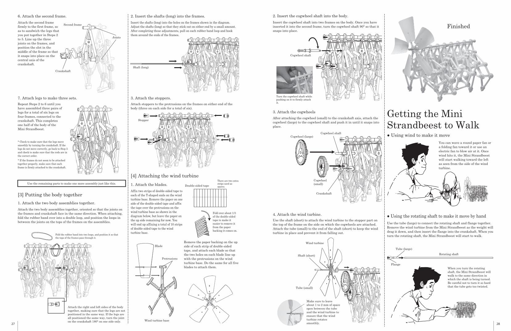
6. Attach the second frame.
Second frame
Joints
Crankshaft
7. Attach legs to make three sets.
[3] Putting the body together
1. Attach the two body assemblies together.
Fold the rubber band into two loops, and position it so that the tops of the frames pass through it.
Attach the second frame firmly to the first frame, so as to sandwich the legs that you put together in Steps 2 to 5. Line up the three joints on the frames, and position the slot in the middle of the frame so that it snaps into place on the central axis of the crankshaft.
2. Insert the shafts (long) into the frames.
3. Attach the stoppers.
Stopper
[4] Attaching the wind turbine
Affix two strips of double-sided tape to each of the T-shaped ends on the wind turbine base. Remove the paper on one side of the double-sided tape and affix the tape over the protrusions on the wind turbine base as shown in the diagram below, but leave the paper on the up side remaining for now. You will end up affixing a total of 10 strips of double-sided tape to the wind turbine base.
Fold over about 1/3 of the double-sided tape to make it easier to remove it from the paper backing it comes on.
Double-sided tape1. Attach the blades.
Remove the paper backing on the up side of each strip of double-sided tape, and attach each blade so that the two holes on each blade line up with the protrusions on the wind turbine base. Do the same for all five blades to attach them.
Use the remaining parts to make one more assembly just like this.
Repeat Steps 2 to 6 until you have assembled three pairs of legs for a total of six legs on four frames, connected to the crankshaft. This completes one half of the body of the Mini Strandbeest.
Insert the shafts (long) into the holes on the frames shown in the diagram. Adjust the shafts (long) so that they stick out on either end by a small amount. After completing these adjustments, pull on each rubber band loop and hook them around the ends of the frames.
Attach the right and left sides of the body together, making sure that the legs are not positioned in the same way. If the legs are all positioned the same way, turn the joint on the crankshaft 180° on one side only.
There are two extra strips used as spares.
* Check to make sure that the legs move smoothly by turning the crankshaft. If the legs do not move correctly, go back to Step 5 and check to make sure that the rods are in the correct order.
* If the frames do not seem to be attached together properly, make sure that each frame is firmly attached to the crankshaft.
Attach the two body assemblies together, oriented so that the joints on the frames and crankshaft face in the same direction. When attaching, fold the rubber band over into a double loop, and position the loops in between the joints on the tops of the frames on the assemblies.
Attach stoppers to the protrusions on the frames on either end of the body (three on each side for a total of six).
Shaft (long)
Wind turbine base
Blade
Protrusions
2. Insert the cogwheel shaft into the body.
Cogwheel shaft
3. Attach the cogwheels
After attaching the cogwheel (small) to the crankshaft axis, attach the cogwheel (large) to the cogwheel shaft and push it in until it snaps into place.
Cogwheel shaft
Crankshaft
Cogwheel (large)
Cogwheel (small)
4. Attach the wind turbine.Use the shaft (short) to attach the wind turbine to the stopper part on the top of the frame on the side on which the cogwheels are attached. Attach the tube (small) to the end of the shaft (short) to keep the wind turbine in place and prevent it from falling out.
Wind turbine
Finished
Getting the Mini Strandbeest to Walk● Using wind to make it move
● Using the rotating shaft to make it move by hand
You can wave a round paper fan or a folding fan toward it or use an electric fan to blow air at it. Once wind hits it, the Mini Strandbeest will start walking toward the left as seen from the side of the wind turbine.
Use the tube (large) to connect the rotating shaft and flange together. Remove the wind turbine from the Mini Strandbeest as the weight will drag it down, and then insert the flange into the crankshaft. When you turn the rotating shaft, the Mini Strandbeest will start to walk.
Flange
Tube (large)
When you turn the rotating shaft, the Mini Strandbeest will walk to the same direction in which the shaft is being turned. Be careful not to turn it so hard that the tube gets too twisted. Tube (small)
Shaft (short) Rotating shaft
Turn the cogwheel shaft while pushing on it to firmly attach it.
Make sure to leave about 1 to 2 mm of space open between the tube and the wind turbine to ensure that the wind turbine rotates smoothly.
Insert the cogwheel shaft into two frames on the body. Once you have inserted it into the second frame, turn the cogwheel shaft 90° so that it snaps into place.