gnss receivers, one step deeper
TRANSCRIPT

DANISH GPS CENTER
GNSS Receivers, One Step Deeper Kai Borre, Head of DGC
Darius Plaušinaitis Danish GPS Center, Aalborg, Denmark

The Signal Reception Problem
• The GNSS signal can be received only when: – The frequency of the local carrier replica matches
the frequency of the carrier in the received signal – The PRN replica code is well aligned in time to the
PRN code in the received signal • There are number of parameters, that
influence how precisely these signals must match to obtain desired processing qualities
2013 Danish GPS Center 2
Carrier wave replica
Incoming signal Correlation result
PRN code replica
Integrator ()2

How Carrier Correlation Works
2013 Danish GPS Center 3
1 2 3 4 5 6 7 8 Correlation

How Code Correlation Works
2013 Danish GPS Center 4
0 1 2 3 4 5 6 7
Incoming code
Generated code
Correlation
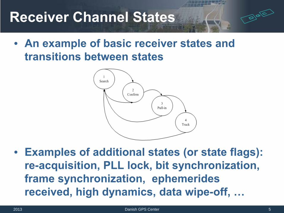
Receiver Channel States
• An example of basic receiver states and transitions between states
• Examples of additional states (or state flags): re-acquisition, PLL lock, bit synchronization, frame synchronization, ephemerides received, high dynamics, data wipe-off, …
2013 Danish GPS Center 5

GNSS Signal Acquisition
• Purpose of acquisition – Find satellites (signals) visible to the receiver – Estimate coarse value for C/A code phase – Estimate coarse value for carrier frequency – Refine carrier search result if it is needed for the
chosen tracking (receiver) design • Acquisition in high sensitivity receivers might
also find bit boundaries • The search space can be reduced if the
receiver has some a priori knowledge about visible GNSS signals
• Re-acquire signals if tracking was interrupted 2013 Danish GPS Center 6

GNSS Signal Acquisition
• Correct values of the code phase (signal alignment in the time domain) and the carrier frequency will yield a high correlation between the locally generated signal and the received GNSS signal
2013 Danish GPS Center 7

Weak Signal Acquisition
• The weak signal acquisition process is an extension of the basic acquisition: – Coherent integration period is increased – Non-coherent integration period is increased
2013 Danish GPS Center 8
∑M ()2
∑M ()2
∑K Correlation
result

Non-Coherent Acquisition • Non-coherent acquisition snapshot was made by student group 1049 (2005)
2013 Danish GPS Center 9

Weak Signal Acquisition Aids
• Additional Information that reduces search space – Precise GNSS time – Approximate position – Ephemerides (or at least almanac data) – Present GNSS signal parameters (Doppler etc.)
• Hardware acceleration – Multiple physical correlators – limited application
• A classical GPS channel is using 2-3 complex correlators
– Other algorithms (parallel processing, FFT etc.) • SirfStarIV – 400000 correlators • u-blox 6 – “over 2 million effective correlators”
2013 Danish GPS Center 10

Carrier Tracking Loop
2013 Danish GPS Center 11
)cos()(21 φnDI =
)cos( φω +nif)cos()( nnD ifω
)sin( φω +nif
)sin()(21 φnDQ =
QI1tan−=φ

Early
Prompt
Late
Received code
-1 -0.5 0 0.5 1 0
0.5
1
Corr
elat
ion
Delay in chips, time
Locally generated
copies of the code
Code Tracking Idea
2013 12 Danish GPS Center

Noncoherent DLL
Local oscillator
PRN code generator
Integrate & dump IE
IP
IL
Incoming signal
E P L
I Integrate & dump
Integrate & dump
90° QE
QP
QL
E P L
Q
Integrate & dump
Integrate & dump
Integrate & dump
Inputs for the discriminator
2013 13 Danish GPS Center

Tracking Results
• Output from the 6 correlators, when the the tracking is locked
2013 Danish GPS Center 14
-6000 -4000 -2000 0 2000 4000 6000
-4000
-2000
0
2000
4000
Discrete-Time Scater Plot
I prompt
Q p
rom
pt
0 100 200 300 400 500 6000
0.5
1
1.5
2
2.5
3x 10
7 Inphase Code Correlators
Time (ms)
Am
plitu
de
0 100 200 300 400 500 6000
0.5
1
1.5
2
2.5
3x 10
7 Quadrature Code Correlators
Time (ms)
Am
plitu
de
IL2
IP2
IE2
QL2
QP2
QE2
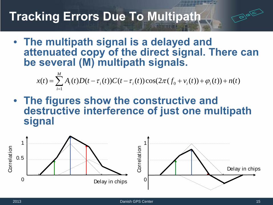
Tracking Errors Due To Multipath
• The multipath signal is a delayed and attenuated copy of the direct signal. There can be several (M) multipath signals.
• The figures show the constructive and destructive interference of just one multipath signal
Corr
elat
ion
Delay in chips 0
0.5
1
Delay in chips
0
1 Co
rrel
atio
n
)())())((2cos())(())(()()( 01
tnttvfttCttDtAtx iiii
M
ii +++−−=∑
=
ϕπττ
2013 15 Danish GPS Center

GNSS Signal Bandwidth and the Measurement Precision Relation
2013 Danish GPS Center 16
Frequency
Frequency

Receiver Tracking Channel
2013 Danish GPS Center 17
Output (nav. data bit stream)
Output (code phase
and count of complete
codes)
Output (carrier phase)
Incoming signal
Local oscillator
PRN code generator
Integrate & dump
IE
IP
IL
E P L
I Integrate & dump
Integrate & dump
90°
QE
QP
QL
E P L
Q
Code loop filter
Code loop discriminator
Integrate & dump
Integrate & dump
Integrate & dump
Carrier loop filter
Carrier loop discriminator

Examples Of Raw Nav. Data
2013 Danish GPS Center 18
-5000 0 5000-5000
-4000
-3000
-2000
-1000
0
1000
2000
3000
4000
5000Discrete-Time Scatter Plot
I prompt
Q p
rom
pt
0 200 400 600 800 1000 1200 1400 1600 1800 2000-6000
-4000
-2000
0
2000
4000
6000
Time (ms)
Prompt I output (strong signal)
-5000 0 5000-5000
-4000
-3000
-2000
-1000
0
1000
2000
3000
4000
5000Discrete-Time Scatter Plot
I prompt
Q p
rom
pt
0 200 400 600 800 1000 1200 1400 1600 1800 2000-2000
-1500
-1000
-500
0
500
1000
1500
Time (ms)
Prompt I output (weak signal)
An example of a strong signal. The
bit transitions are clearly
visible.
An example of a weak
signal. The bit transitions
are not so clear.

An Example Of a GPS Sub-frame
2013 Danish GPS Center 19

First Words Of a Subframe
2013 20 Danish GPS Center

GPS Navigation Data Contents
2013 Danish GPS Center 21

Error Detection And Correction
• Three types of techniques that deal with bit errors in transmitted/received signals: – Error detection: CRC, parity check – Error detection an correction: parity check,
FEC – Techniques to mitigate loss or corruption of
a series of bits (burst errors): block interleaving
2013 Danish GPS Center 22

An Example Of Interleaved Data Corruption
… , 0 1 0 1 1 1 0 1 1, 1 0 1 0 1 1 0 1 0, 0 0 0 1 1 0 1 0 0, 0 1 1 0 0 1 0 1 1, 1 0 1 1 0 0 1 0 1, …
2013 Danish GPS Center 23
… , 0 1 0 0 1, 1 0 0 1 0, 0 1 0 1 1, 1 0 1 0 1, 1 1 1 0 0, 1 1 0 1 0, 0 0 1 0 1, 1 1 0 1 0, 1 0 0 1 1, …
0 1 0 1 1 1 0 1 1 1 0 1 0 1 1 0 1 0 0 0 0 1 1 0 1 0 0 0 1 1 0 0 1 0 1 1 1 0 1 1 0 0 1 0 1
Deinterleaving

GNSS Software Defined Radios (SDR) And Other Alternatives
2013 Danish GPS Center 24
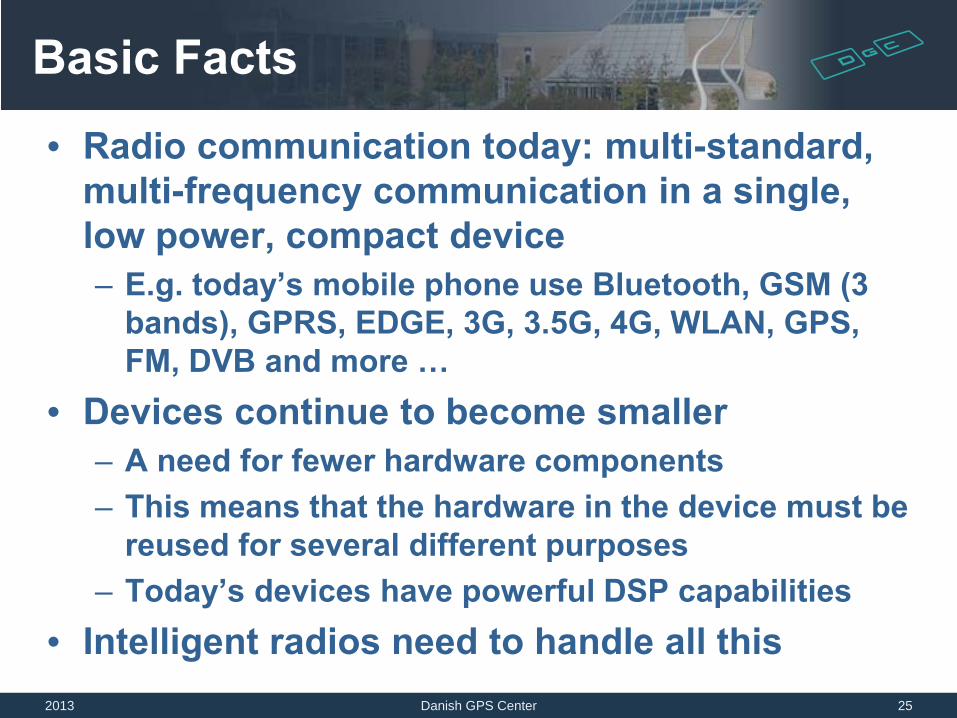
Basic Facts
• Radio communication today: multi-standard, multi-frequency communication in a single, low power, compact device – E.g. today’s mobile phone use Bluetooth, GSM (3
bands), GPRS, EDGE, 3G, 3.5G, 4G, WLAN, GPS, FM, DVB and more …
• Devices continue to become smaller – A need for fewer hardware components – This means that the hardware in the device must be
reused for several different purposes – Today’s devices have powerful DSP capabilities
• Intelligent radios need to handle all this 2013 Danish GPS Center 25

Basic Facts (GNSS Receivers) • GNSS positioning is also becoming multi-standard
and multi-frequency – GPS II, GPS modernizations: M code and L2C, L5 signals,
L1C(GPS III) – Galileo – GLONASS + modernized signals – QZSS (Japan), IRNSS (India), and Beidou (China) – SBAS systems: EGNOS, WAAS, MSAS, GAGAN
• Today GNSS receivers often are part of devices which have other radios too (hardware reuse)
2013 Danish GPS Center 26

GNSS SDR Partitioning
2013 Danish GPS Center 27
ADC Correlators (Channels)
Channel loop closure, Positioning
Radio front-end (analogue)
Position
ADC Correlators (Channels)
Channel loop closure, Positioning
Radio front-end (analogue)
Position
ADC Correlators (Channels)
Channel loop closure, Positioning
Position
Hardware
Software
Traditional Receiver
Software Defined Receiver
”Ideal” Software Receiver

Solutions
• To use general hardware per new signal or ASIC (Application Specific Integrated Circuit)
• To use reconfigurable hardware – FPGA (Field Programmable Gate Array), etc.
• To use DSP (Digital Signal Processor) • To use a general purpose processor (CPU) –
x86, ARM, etc.
2013 Danish GPS Center 28
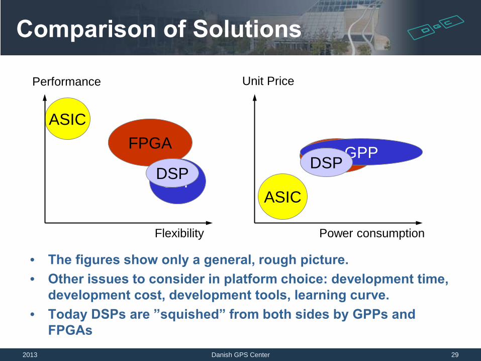
Comparison of Solutions
• The figures show only a general, rough picture. • Other issues to consider in platform choice: development time,
development cost, development tools, learning curve. • Today DSPs are ”squished” from both sides by GPPs and
FPGAs 2013 Danish GPS Center 29
Flexibility
Performance
ASIC FPGA
Power consumption
Unit Price
ASIC
FPGA GPP DSP GPP DSP

SDR Practical Conclusions • Very, very flexible • Matlab enables to write and test algorithms very
quickly (real life example: 6-8 lines in Matlab vs. 2000 lines in VHDL)
• Can be very slow (e.g. pure Matlab version) – Matlab version of a GPS receiver is a few hundred times
slower than real-time – Matlab & C code is close to real time (4 channels on a fast PC)
• Real-time GNSS SDR implementations exist (written in C) for embedded and for PC applications. A very fast PC can process about 5 x 12 channels in real-time (2011)
2013 Danish GPS Center 30

SDR Advantages • A very convenient educational tool • Quick prototyping
• A demo acquisition for Galileo in less than an hour • Students have converted the GPS SDR to EGNOS and Galileo
SDRs in ~6 month
• SDR enables alternative positioning methods (e.g. non-real time)
• “Easy” exploration of particular signal cases (anomalies) or algorithms because the GNSS signal record can be replayed again and again…
2013 Danish GPS Center 31

Data Aiding
GNSS Snapshot Idea
2013 Danish GPS Center 32
Compact, low power snapshot
device (rover) RF front-end
Amplifier
GNSS antenna
A/D
Signal recording
Memory
Software that does GNSS signal processing,
derives measurements and does the actual position computation
Additional tasks can be
precision improvement or GNSS signal validation
Multi-frequency, multisystem
GNSS receiver
Receiver clock
Frequency synthesizer
Mixer
SBAS DGPS
PVT solution
…
Wireless or other
type data delivery

GNSS Snapshot Technique • The rover devices can be a low power type devices (on the
opposite – the ordinary GPS is a very power consuming device) • The rower device is relatively GNSS system independent, and
GNSS modernization independent • The server software implements nearly all GNSS system
dependent signal processing parts – one place to update system capabilities
• The server software can have more time, power and also other types of resources to do position estimation
• The server software can implement signal authentication, validation checks using all available resources
• Usually – not for true real-time applications
2013 Danish GPS Center 33

SDR Demo
2013 Danish GPS Center 34

Current Receiver Development
2013 Danish GPS Center 35
2007 Future Research and development
2008-2010
•High sensitivity •Multi-system & multi-frequency receiver •Multipath mitigation •Further SDR development •GNSS integrity •Integration of other kinds of positioning

The ML507 Setup
2013 Danish GPS Center 36
Battery adapter
GNSS front-end

Simulink Model
2013 Danish GPS Center 37
The adaptor block inside calls nearly unmodified C code of the FPGA receiver

Matlab SDR Plots
2013 Danish GPS Center 38
4 4.005 4.01 4.015 4.02 4.025 4.03 4.035
x 104
-2000
0
2000
4000
6000
Samples (time)
Cor
rela
tion
Real correlation result from GNSS SDR
-1 0 1 2 0
0.5
1
1.5
Code Offset [chips]
Cor
rela
tion
Theoretical correlation
0 5 10 15 20 25 300
5
10
15Acquisition results
PRN number (no bar - SV is not in the acquisition list)
Acqu
isitio
n Metr
ic
Not acquired signalsAcquired signals

Matlab SDR
2013 Danish GPS Center 39
postProcessing.m script
postNavigation.m USB driver (C)
Recorder application (C, C++)
Signal record file (1 byte per sample)
probeSignal.m
acquisition.m
tracking.m
satPos.m
plotTracking.m
plotNavigation.m
Coordinate transformations
findPreambles.m
ephemeris.m
leastSquarePos.m

Commercial DGPS Performance
2013 Danish GPS Center 40

SDR Modification For Galileo
2013 Danish GPS Center 41
One sub-frame

Thank You For Your Attention
http://gps.aau.dk
2013 42 Danish GPS Center
DANISH GPS CENTER
Il contenuto del documento, comprensivo di tutte le informazioni, dati, comunicazioni, grafica, testi, tabelle, immagini, foto, video, disegni, suoni e in generale ogni altra informazione disponibile in qualunque forma e qualsiasi materiale e servizio ivi presente è di proprietà di Sogei e/o degli autori e/o dei titolari dei materiali pubblicati ed è tutelato ai sensi della normativa in materia di diritto d'autore e di opere dell'ingegno.
Non è consentito utilizzare, copiare, alterare, pubblicare e distribuire il documento, dati e informazioni e relative immagini riportate nello stesso, salvo permesso scritto validamente espresso da Sogei e fatte salve eventuali spettanze di diritto. Le note di copyright, gli autori ove indicati o la fonte stessa devono in tutti i casi essere citati nelle pubblicazioni in qualunque forma realizzate e diffuse.
The content of the document, including all the information, data, communications, code, graphics, text, tables, images, photos, videos, music, drawings, sounds and in general all other information available in any form and any material and service present is the property of Sogei and/or the authors and/or of its licensees and assignors and is protected under the terms of legislation on copyright and intellectual property. It is forbidden to use, copy, alter, publish or distribute the documents, data and information and the associated images available on this document, without the written permission validly expressed by Sogei and always subject to any legal rights. The copyright notes, the authors where indicated or the source itself must in all cases be quoted in publications produced and distributed in any form.