gohfn wolf - ct.gov-connecticut's official state …€¦ · gohfn wolf ~p.c.~ attorneys at...
TRANSCRIPT
GOHFNWOLF~P.C.~ATTORNEYS AT LAW JULIE D. KOHLER
PLEASE REPLY TO: BI'Id eCLpOft
WRITER'S DIRECT DIAL: 203) 337-4157
E-Mail Address: jkohler(c~cohenandwolf.com
January 20, 2015
Attorney Melanie BachmanActing Executive DirectorConnecticut Siting CouncilTen Franklin SquareNew Britain, CT 06051
Re: Notice of Exempt ModificationNortheast Utilties/T-Mobile equipment upgradeSite ID CT11111A20 Barnabas Road, Newtown, Connecticut
Dear Attorney Bachman:
This office represents T-Mobile Northeast LLC ("T-Mobile") and has been retained tofile exempt modification filings with the Connecticut Siting Council on its behalf.
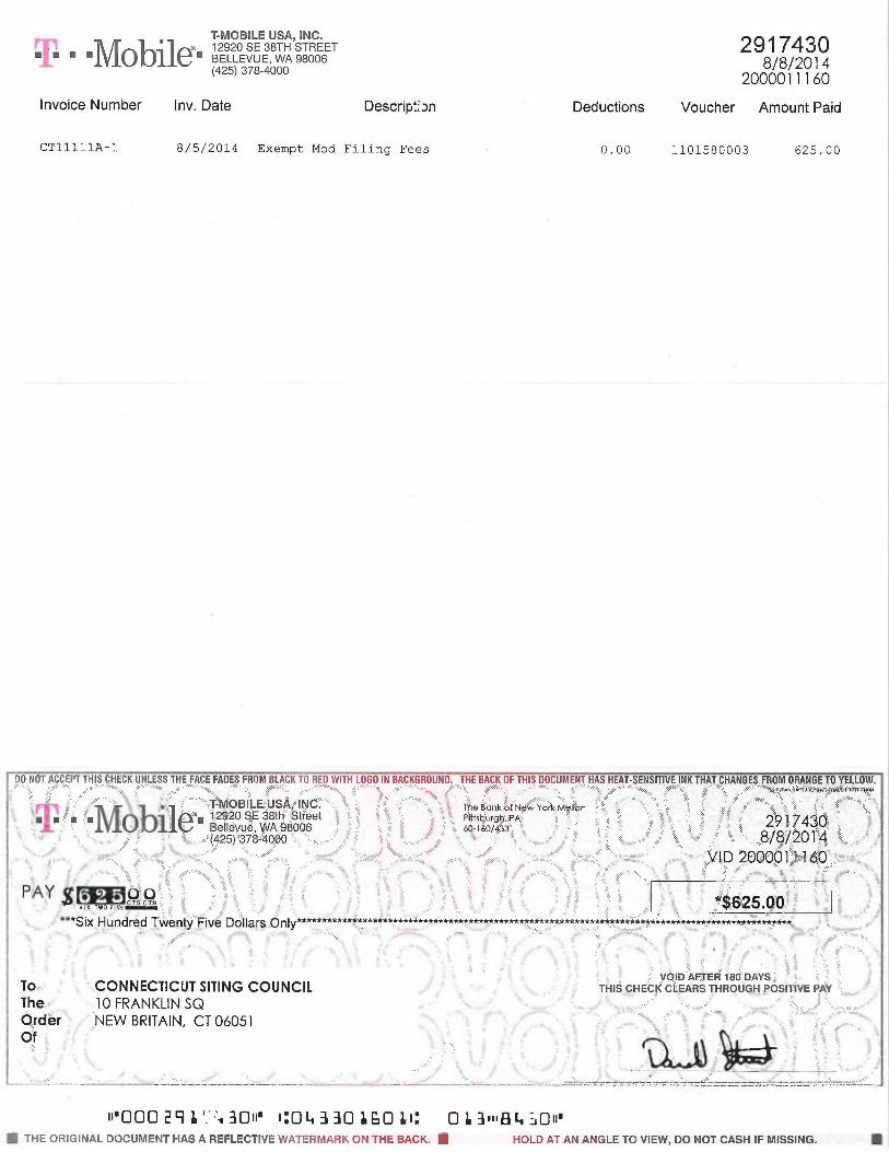
In this case, Northeast Utilities owns the existing lattice tower and related facility locatedat 20 Barnabas Road, Newtown, Connecticut (Latitude: 41.42762905 Longitude: -73.3436).T-Mobile intends to remove three (3) antennas and three (3) TMAs (tower mounted amplifiers)and add six (6) panel antennas and related equipment at this existing telecommunicationsfacility in Newtown ("Newtown Facility"). Please accept this letter as notification, pursuant toR.C.S.A. § 16-50j-73, of construction which constitutes an exempt modification pursuant toR.C.S.A. § 16-50j-72(b)(2). In accordance with R.C.S.A. § 16-50j-73, copies of this letter arebeing sent to the First Selectman, E. Patricia Llodra, and the property owner, Barnabas RealtyGroup General Partnership.
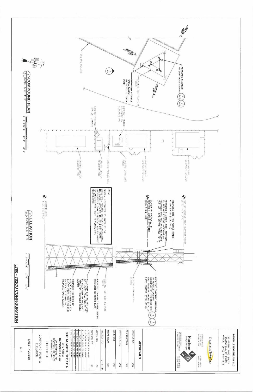
The existing Newtown Facility consists of a 180 foot tall lattice tower, approved by theCouncil in Docket No. 144.' T-Mobile plans to remove three (3) antennas and three (3) TMAs(tower mounted amplifiers) and add six (6) panel antennas on three (3) proposed mounts at acenterline of 149 feet. T-Mobile will also add fiber and coax cables and relocate existing coaxcables on a proposed cable ladder. (See the plans revised to January 12, 2015 attachedhereto as Exhibit A). The existing Newtown Facility is structurally capable of supporting T-Mobile's proposed modifications, as indicated in the structural analysis dated November 10,2014 and attached hereto as Exhibit B.2
The Decision and Order in this docket (dated November 20, 1991) contains no relevant requirements orlirnitations on the configuration of the Newtown Facility.Z The structural analysis provides that the tower is adequate to support the proposed equipment with thereinforcements detailed in Section 4 in the report. Those reinforcements will be completed prior to the installationof the proposed modifications.
I I IS BROAD STREET ISH DEER HII.L AVENUE 320 PosT Rona WasT GSA ORANGE CANTER ROAD
P.O. BOX IHZI DANBURY, Cr O6HIO ~ WESTPORT, CI' 06880 ORANGE, CT OG47~
BRIDGEPORT, CI' 06601-1821 Te[,: (203) 792 2771 Ts[.: (203) 222-1034 1'&L: (203) 298-4066Tit: (203) 368-0211 Fnx: (203) 791-8149 Fax: (203) 227-1373 Fnx: (203) 298 068Fwx: (203) 3949901
COHFNWOLF_~~:_ATT OR~EI'.S \T I.aP
January 20, 2015Site ID CT11111APage 2
1 . The proposed modification will not increase the height of the tower. T-Mobile'sproposed modifications will be installed at a centerline of 149 feet, merely modifying existingantennas located at the same 149 foot elevation. The enclosed tower drawing confirms thatthe proposed modification will not increase the height of the tower.
2 . The proposed modifications will not require an extension of the site boundaries.T-Mobile proposes no changes to the existing compound and equipment pad.
3 . The proposed modification to the Newtown Facility will not increase the noiselevels at the existing facility by six decibels or more.
4 . The operation of the replacement/additional antennas will not increase the totalradio frequency (RF) power density, measured at the base of the tower, to a level at or abovethe applicable standard. According to a Radio Frequency Emissions Analysis Report preparedby EBI dated December 4, 2014, T-Mobile's operations would add 4.92% of the FCCStandard. Therefore, the calculated "worst case" power density for the planned combinedoperation at the site including all of the proposed antennas would be 73.35% of the FCCStandard as calculated for a mixed frequency site as evidenced by the engineering exhibitattached hereto as Exhibit C.
CL&P has authorized the filing of this exempt modification as evidenced by the letter ofauthorization signed January 19, 2015 attached hereto as Exhibit D.
For the foregoing reasons, T-Mobile respectfully submits that the proposedreplacement/additional antennas and equipment at the Newtown Facility constitutes anexempt modification under R.C.S.A. § 16-50j-72(b)(2). Upon acknowledgement by the Councilof this proposed exempt modification, T-Mobile shall commence construction approximatelysixty days from the date of the Council's notice of acknowledgement.
Sincerely,
~~ . ~~
Jul e D. Kohler, Esq.
cc: Town of Newtown, First Selectman E. Patricia Llo~raNortheast UtilitiesBarnabas Realty Group General PartnershipElizabeth Jamieson,Transcend Wireless
T-MOBILE USA, INC.0 12920 SE 38TH STREET
~ . ~ ~ ~1Vlobile ~ BELLEVUE, WA 98006(425) 378-4000
Invoice Number Inv. Date Descrip:;~n Deductions
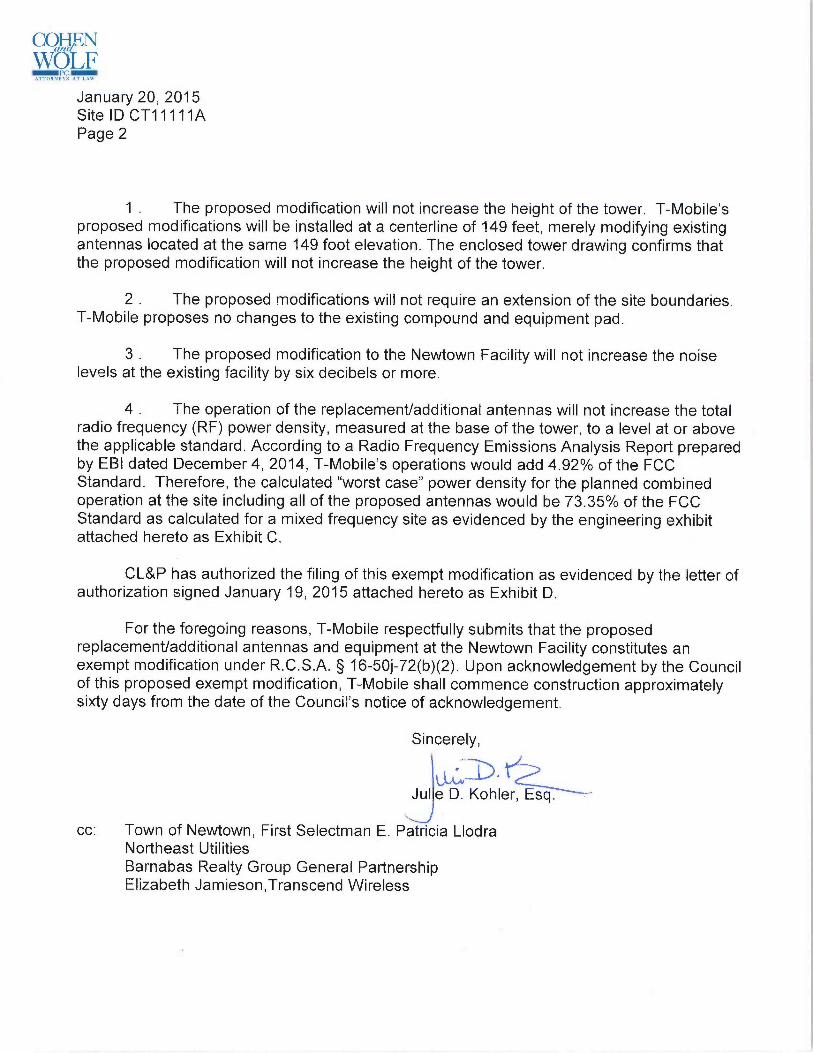
CT11111A-1 8/5/2014 Exempt Mod Filing Fees 0.00
29174308/8/2014
2000011160
Voucher Amount Paid
1101580003 625.00
DO NOT ACCEPT THIS CHECK UNLESS THE FACE FADES FROM BLRCK TO RED WITH LOGD IN BAGKGROUNU. THE BACK Of THIS DOCUMENT HAS HEAT-SENSITIVE INK THAT CHANGES FROM ORANGE TD YELLDW.r -~. ~- _ / ~ ~ \ ~~~~~
. :>~ .....~ ~~\ \ -.~ "~.~ \ / ~a .~~/ //~..; „\\ ;
'~`~Ro \ ~ nvn,~~,n caaU nAalc~~x
~~ ~, ~ YMOBF~E?US~,~INC ~ ~ ~ ~ ~'~ Tfie B'ank,''flzN~YorI~~IFAn ~ •~ ~-■ ■ ~ ■ ■ ~2 ~0 ~E ~Sth ~t~eet • . ~ P1~t5eurgr~ ~A- ~ 2~ ~ ~4~~~' ~ ~q~~~~~ ~e~Yleyue, ~+/A;~J8006 so-i6o/~~' \
' ~./~ (425) ;378=4000 ~ ~.•~• ~ ~ ~ ~ ~ ,.~~~~~~ ~~
~~ ~, ~ ~ ~~ i ~ ~ ~.PAY ~[ ~ b O ~ ' ;.
'~ 51% TWO FIVE CT~r ~ ~ `. j, / ~". y ~ / ~ ~ /'~ ~ \ ~;T \ ̀~ "`~C25 ~0'~~..~ ~'.:.*Six Hundred Twenty Fiv~Dollars Only.~.**,~,~~:*#.******.**~*~~*,~~*.,**,~..,t,..,.,,,.*«***.;~*~*~~*~~~«.,** ,
~~**w**,.~„***„~*...,~.~~**.~*~#.:.;~ ;,«, ,',
,
~~
~;i VOID AFTER 180- DAYS
To-,<~ ~~,.CONNECTICUTSITINGCOUNCIL ~ rHiscHecKc~E,a~~sr-Hapuc,Haosi~~ve~,~r ~~The--~ 10 FRANKLIN SQ ~ ,r' ~ . ~~~< ..,,,.~C~rder~ NEW BRITAIN, CT 06051 ~ ~ ~ ~~V '' ~~ i~~~~ ~~ ~~~~
~' ~ ~~Q.~s~~~ ~..
i~'000 29 L ̀ .", 30ii' x:04 3 30 L60 ~~: 0 L 3~~~84 ~Oii'~ THE ORIGINAL DOCUMENT HAS A REFLECTIVE WATERMARK ON THE BACK. ~ HOLD AT AN ANGLE TO VIEW, Dd NOT CASH IF MISSING. ~

SITE NANi E: N EWTOWN/ I-84 X
9NEWTOWN SERVICE CENTER
20 BARNABUS RD.
NEWTOWN, CT 06470
FAIRFIELD COUNTY
SITE NUMBER: CT11111 A
L700 - 7
02CC CONFIGURATION
GENERAL NOTES
1. THIS DOCUMENT IS
THE CREATION, DESIGN, PROPERTY AND COPYRIGHTED WORK OF
T—MOBILE. ANY DUPLICATION
OR USE WITHOUT EXPRESS WRITTEN
CONSENT IS
STRICTLYPROHIBITED. DUPLICATION
AND USE BY GOVERNMENT AGENCIES FOR THE PURPOSES OF
CONDUCTING THEIR
LAWFULLY AUTHORIZED REGULATORY AND ADMINISTRATIVE
FUNCTIONS IS
SPECIFICALLY ALLOWED.
2. THE FACILITY
IS AN UNMANNED PRIVATE
AND SECURED EQUIPMENT INSTALLATION. IT
IS ONLY
ACCESSED BY TRAINED TECHNICIANS FOR PERIODIC
ROUTINE MAINTENANCE AND THEREFORE
DOES NOT REQUIRE ANY WATER OR SANITARY SEWER SERVICE.
THE FACILITY
IS NOT
GOVERNED BY REGULATIONS REQUIRING PUBLIC ACCESS PER ADA REQUIREMENTS.
3. CONTR4CTOR SHALL VERIFY
ALL PLANS AND EXISTING
DIMENSIONS AND CONDITIONS ON THE
JOB SITE
AND SHALL IMMEDIATELY
NOTIFY THE T—MOBILE NORTHEAST, LLC REPRESENTATIVE
IN WRITING
OF DISCREPANCIES BEFORE PROCEEDING WITH
THE WORK OR BE RESPONSIBLE
FOR SAME.
SPECIAL STRUCTURAL NOTES
1. STRUCTUR4L DESIGNS AND DETAILS
FOR ANTENNA MOUNTS COMPLETED BY HUDSON DESIGN
ON BEHALF OF T—MOBILE ARE INCLUSIVE
OF THE ENTIRE
ANTENNA SUPPORT STRUCTURE
(GLO&4L STRUCTUR4L
STABILITY ANALYSIS BY OTHERS),
EXISTING TOWER
PLATFORM,
EXISTING ANTENNA MOUNTS AND ALL OTHER ASPECTS OF THE STRUCTURE THAT WILL
SUPPORT THE T—MOBILE MODERNIZATION EQUIPMENT DEPLOYMENT AS DEPICTED HEREIN.
2. HUDSON DESIGN ASSUMES THAT THE TOWER IS
PROPERLY CONSTRUCTED AND MAINTAINED.
ALL STRUCTUR4L MEMBERS AND THEIR
CONNECTION ARE ASSUMED TO BE
IN GOOD
CONDITION AND ARE FREE FROM DEFECTS WITH
NO
DEfERI0R4TI0N TO
ITS MEMBER
CAPACITIES
T-MOBILE TECHNICIAN SITE SAFETY NOTES
LOCATION
SPECIAL RESTRICTIONS
SECTOR A:
ACCESS NOT PERMITTED
SECTOR B:
ACCESS NOT PERMITTED
SECTOR C:
ACCESS NOT PERMITTED
GPS/LMU:
UNRESTRICTED
RADIO CABINETS:
UNRESTRICTED
PPC DISCONNECT:
UNRESTRICTED
MAIN CIRCUIT
D/C:
UNRESTRICTED
NIU/T DEMARC:
UNRESTRICTED
OTHER/SPECIAL:
NONE
CALL
BEFORE YOU DIG
CALL TOLL FREE 800-922-4455
OR CALL 81 1
UNDERGROUND SERVICE ALERT
PROJECT INFORMATION
SCOPE OF WORK:
UNMANNED TELECOMMUNICATIONS FACILITY T
—MOBILE
EQUIPMENT MODERNIZATION
ZONING JURISDICTION:
BASED ON INFORMATION PROVIDED BY T—MOBILE, THIS
TELECOMMUNICATIONS EQUIPMENT DEPLOYMENT IS
AN
ELIGIBLE FACILITY
UNDER THE TAX RELIEF A
CT OF 2012,
47 USC 1455(A), A
ND IS
SUBJECT TO AN EXPEDITED
ELIGIBLE FACILITIES
REQUEST/REVIEW AND ZONING
PRE—EMPTION FOR LOCAL DISCRETIONARY PERMITS
(VARIANCE, SPECIAL PERMIT, SITE
PLAN REVIEW).
SITE ADDRESS:
20 BARNABUS RD
NEWTOWN, CT 06470
LATITUDE: 41' 2
5' 39.468" N
LONGITUDE:
73' 20' 36.9594" W
JURISDICTION: NATIONAL, S
TATE &LOCAL CODES OR ORDINANCES
CURRENT USE:
TELECOMMUNICATIONS FACILITY
PROPOSED USE:
TELECOMMUNICATIONS FACILITY
DRAWING INDEX
REV
T-1 TITLE SHEET
6
GN-1 GENERAL NOTES
6
A-1 COMPOUND ~ ELEVATION PLAN
S
A-2 ANTENNA PLAN &DETAILS
6
G-1 GROUNDING DETAILS
6
T-MOBILE NORTHEAST LLC
35 GRIFFlN
ROAD SOUTH
BLOOMFIELD, CT 06002
OFFICE: (860) 648-1116
Transcend lNir~/ess
TRANSCEND WIRELESS
101NDU5TRIAL AVE
iE1: (201 684-0055
MAHWAH, NJ 07430
FAX:(201~684-0066
Hudson~~
Design Graapuc
iecooscoo~sme~BUILDING 2
0 NORTH, SURE 3090
TEL: X978) 557-5553N. A
NDOVER, MA 07845
FAX: ~978~ 336-5586
APPROVALS
CONSTRUCTION DATE
RF ENGINEERING DATE
ZONING/SITE ACQ. DATE
OPERATIONS DATE
TOWER OWNER
DATE
PROJECT N0:
CT11111A
DRAWN BY:
AS
CHECKED BY:
DR
6 01/12/75 ISSUED FOR REVIEW
5 01/08/15 ISSUED FOR REVIEW
4 72/22/14 ISSUED FOR REVIEW
3 11/26/14 ISSUED FOR REYIEW
2 08/25/14 ISSUED FOR REVIEW
7 08/22/14 ISSUED FOR REVIEW
0 08/11/74 ISSUED FOR REVIEW
SITE NUMBER: CT11111A
SITE NAME:
NEWTOWN/ 1-84 X9
20 BARNABUS RD
NEWTOWN, CT 06470
FAIRFIELD COUNTY
SHEET TITLE
TITLE SHEET
SHEET NUMBER
T-1
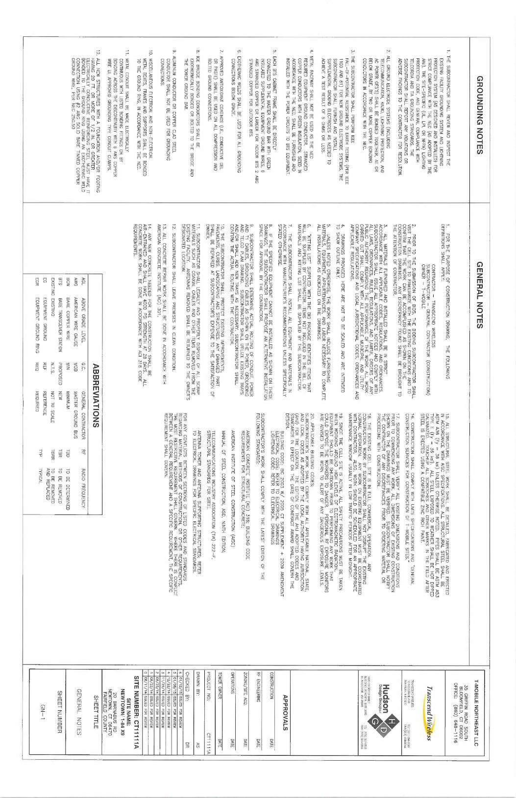
GROUNDING NOTES
1. THE SUBCONTR4CTOR SHALL REVIEW
AND INSPECT T
HE
EXISTING FACILITY G
ROUNDING SYSTEM
AND LIGHTNING
PROTECTION SYSTEM (
AS DESIGNED
AND INSTALLED) F
OR
STRICT COMPLIANCE WITH THE NEC (AS ADOPTED BY THE
AHJ), THE SITE-SPECIFIC (UL, LPI, O
R NFPA) LIGHTfNG
PROTECTION CODE, AND GENERAL COMPLIANCE
WITHTELCORDIA A
ND TIA
GROUNQING STANDARDS. T
HE
SUBCONTRACTOR SHALL REPORT ANY VIOLATfONS O
RADVERSE FINDINGS T
O THE CONTRACTOR FOR RESOLUTION.
2. ALL GROUND ELECTRODE SYSTEMS (fNCLUDING
TELECOMMUNICATION, RADIO, LIGHTNING PROTECTION, A
ND
AC POWER GES'S) S
HALL BE BONDED TOGETHER, AT O
RBELOW GRADE, B
Y TWO OR MORE COPPER BONDING
CONDUCTORS IN
ACCORDANCE WITH
THE NEC.
3. THE SUBCONTRACTOR SHALL PERFORM IEEE
FALL -OF-POTENTIAL RESISTANCE T
O EARTH TESTING (
PER IEEE
1100 ANO 81) FOR NEW GROUND ELECTRODE SYSTEMS. T
HE
SUBCONTRACTOR SHALL FURNISH
AND INSTALL
SUPPLEMENTAL GROUND ELECTRODES AS NEEDEQ TO
ACHIEVE A TEST RESULT O
F 5 OHMS OR LESS.
4. METAL R4CEWAY SHALL NOT BE USED AS THE NEC
REQUIRED EQUIPMENT GROUND CONDUCTOR. STRANDED
COPPER CONDUCTORS WITH
GREEN INSULATION, SIZED
INACCORDANCE WITH T
HE NEC, S
HALL BE FURNISHED
AND
INSTALLED WITH T
HE POWER CIRCUITS T
O 8T5 EQUIPMENT.
5. EACH BTS CABINET F
RAME SHALL BE DIRECTLY
CONNECTED TO THE MASTER
GROUND BAR
WITH GREEN
fNSULATED SUPPLEMENTAL EQUIPMENT GROUND WIRES, 6
AWG STRANDED COPPER OR LARGER
FOR INDOOR
BTS 2 AWG
STRANDED COPPER FOR OUTDOOR BTS.
6. EXOTHERMIC WELDS SHALL BE USED FOR ALL G
ROUNDING
CONNECTIONS BELOW GRADE.
7. APPROVED ANTIOXIDANT COATINGS (I.E., CONDUCTIVE
GEL
OR PASTE) S
HALL BE USED ON ALL C
OMPRESSION AND
BOLTED GROUND CONNECTIONS.
8. ICE BRIDGE BONDING CONDUCTORS SHALL BE
EXOTHERMICALLY BONDED OR BOLTED T
O THE BRIDGE A
ND
THE TOWER GROUND BAR.
9. ALUMINUM CONDUCTOR OR COPPER CLAD
STEELCONDUCTOR SHALL NOT BE USED FOR GROUNDING
CONNECTIONS.
10. MISCELLANEOUS ELECTRICAL A
ND NON-ELECTRICAL
METAL BOXES, FRAMES AND SUPPORTS SHALL BE BONDED
TO THE GROUND RING, IN
ACCORDANCE WITH T
HE NEC.
11. METAL CONDUIT SHALL BE MADE ELECTRICALLY
CONTINUOUS WITH
LISTED BONDING FITTINGS O
R BY
BONDING ACROSS THE DISCONTINUITY WITH 6
AWS COPPER
WIRE UL APPROVED GROUNDING TYPE CONDUIT CLAMPS.
12. ALL NEW STRUCTURES WITH
A FOUNDATION AND/OR FOOTING
HAVING 20 FT. O
R MORE OF 1/2 IN.
OR GREATER
ELECTRICALLY CONDUCTIVE REINFORCING STEEL MUST HAVE IT
BONDED TO THE GROUND RING
USING AN EXOTHERMIC WELD
CONNECTION USING #2 AWG SOLIp BARE TINNED COPPER
GROUND WIRE, P
ER NEC 250.50
GENERAL NOTES
1. FOR THE PURPOSE OF CONSTRUCTION DRAWING, THE FOLLOWWG
DEFINITIONS SHALL APPLY:
CONTRACTOR -TRANSCEND WIRELESS
SUBCONTRACTOR -GENERAL CONTRACTOR (CONSTRUCTION)
OWNER - T-
MOBILE
2. PRIOR TO THE SUBMISSION OF BIDS, T
HE BIDDING
SUBCONTR4CTOR SHALL
VISIT THE CELL SITE T
O FAMILIARIZE
WITH THE EXISTING
CONDITIONS AND TO
CONFIRM THAT THE WORK CAN BE ACCOMPLISHED AS SHOWN ON THE
CONSTRUCTION DRAWWGS. ANY DISCREPANCY FOUND SHALL BE BROUGHT TO
THE ATTENTION
OF CONTRACTOR.
3. ALL MATERIALS
FURNISHED AND INSTALLED
SHALL BE IN
STRICTAGCORDANCE WITH
ALL APPLICABLE CODES, REGULATIONS, AND ORDINANCES:
SUBCONTRACTOR SHALL ISSUE ALL APPROPRIATE NOTICES AND COMPLY WITH
ALL LAWS, ORDINANCES, RULES, REGULATIONS, AND LAWFUL ORDERS OF ANY
PUBLIC AUTHORITY REGARDING THE PERFORMANCE OF THE WORK. ALL WORK
CARRIED OUT SHALL COMPLY WITH
ALL APPLICABLE MUNICIPAL A
ND UTILITY
COMPANY SPECIFICATIONS
AND LOCAL JURISDICTIONAL C
ODES, ORDINANCES AND
APPLICABLE REGULATIONS.
4. DRAWINGS PROVIDED HERE ARE NOT TO BE SCALED AND ARE INTENDED
TO SHOW OUTLINE ONLY.
5. UNLESS NOTED OTHERWISE, THE WORK SHALL INCLUDE FURNISHING
MATERIALS, EQUIPMENT, APPURTENANCES, AND LABOR NECESSARY TO COMPLETE
ALL INSTALLATIONS
AS INDICATED
ON THE DRAWINGS.
6.
"KITTING LIST" S
UPPLIED WITH
THE BID
PACKAGE IDENTIFIES
ITEMS THAT
WILL BE SUPPLIED BY CONTRACTOR. ITEMS
NOT INCLUDED IN
THE BILL O
FMATERIALS
AND KITTING
LIST SHALL BE SUPPLIED BY THE SUBCONTRACTQR.
7. THE SUBCONTRACTOR SHALL INSTALL
ALL EQUIPMENT AND MATERIALS IN
ACCORDANCE WITH
MANUFACTURER'S RECdMMENDATIONS UNLESS SPECIFICALLY
STATED OTHERWISE.
8. IF T
HE SPECIFIED
EQUIPMENT CANNOT BE INSTALLED
AS SHOWN ON THESE
DRAWINGS, THE SUBCONTRACTOR SHALL PROPOSE AN ALTERNATIVE
INSTALLATIONSPACE FOR APPROVAL BY THE CONTRACTOR.
9. SUBCONTRACTOR SHALL DETERMINE ACTUAL ROUTING OF CONDUIT, POWER
AND T1
CABLES, GROUNDING CABLES AS SHOWN ON THE POWER, GROUNDING
AND TELCO PLAN DRAWWG. SUBCONTRACTOR SHALL UTILJZE
IXISTING TRAYS
AND/OR SHALL ADD NEW TRAYS AS NECESSARY. SUBCONTRACTOR SHALL
CONFIRM THE ACTUAL ROUTING WITH
THE CONTRACTOR.
10. THE SUBCONTRACTOR SHALL PROTECT EXISTING
IMPROVEMENTS,
PAVEMENTS, CURBS, LANDSCAPING AND STRUCTURES. ANY DAMAGED PART
SHALL BE REPAIRED AT SUBCONTRACTOR'S EXPENSE TO THE SATISFACTION
OF
OWNER.
11. SUBCONTRACTOR SHALL LEGALLY AND PROPERLY DISPOSE OF ALL SCR4P
MATERIALS SUCH AS COAXIAL
CABLES AND OTHER ITEMS
REMOVED FROM THE
EXISTING FACILITY.
ANTENNAS REMOVED SHALL BE RETURNED TO THE OWNER'S
DESIGNATED LOCATION.
12. SUBCONTRACTOR SHALL LEAVE PREMISES IN
CLEAN CONDITION.
13. ALL CONCRETE REPAIR
WORK SHALL BE DONE IN
ACCORDANCE WITH
AMERICAN CONCRETE INSTITUTE (ACT) 3
0i.
14. ANY NEW CONCRETE NEEDED FOR THE CONSTRUCTION SHALL BE
AIR-ENTRAINED AND SHALL HAVE 4000 P51
STRENGTH AT 28 DAYS. ALL
CONCRETE WORK SHALL BE DONE IN
ACCORDANCE WITH
ACI 318 CODE
REQUIREMENTS.
15. ALL STRUCTURAL STEEL WORK SHALL BE DETAILED, F
ABRICATED AND ERECTED
IN ACCORDANCE WITH
AISC SPECIFICATIONS. ALL STRUCTURAL STEEL SHALL BE
ASTM A36 (Fy = 36 ksi)
UNLESS OTHERWISE NOTED.
PIPES SHALL BE ASTM A53
TYPE E (Fy = 36 ksi).
ALL STEEL EXPOSED TO WEATHER SHALL BE HST DIPPED
GALVANIZED. TOUCHUP ALL SCRATCHES AND OTHER MARKS IN
THE FIELD
AFTER
STEEL IS
ERECTED USING A COMPATIBLE ZINC RICH
PAINT.
16. CONSTRUCTION SHALL COMPLY WITH
UMTS SPECIFICATIONS
AND °GENERAL
CONSTRUCTION SERVICES FOR CONSTRUCTION OF T-
MOBILE SITES."
17. SUBCONTRACTOR SHALL VERIFY
ALL EXISTING
DIMENSIONS AND CONDITIONS
PRIOR TO COMMENCING ANY WORK. ALL DIMENSIONS OF EXISTING
CONSTRUCTION
SHOWN ON THE DRAWINGS MUST BE VERIFIED.
SUBCONTRACTOR SHALL NOTIFY
THE CONTRACTOR OF ANY DISCREPANCIES PRIOR TO ORDERING MATERIAL O
RPROCEEDING WITH
CONSTRUCTION.
18. THE EXISTING
CELL SITE
IS IN
FULL COMMERCIAL QPERATION. ANY
CONSTRUCTION WORK BY SUBCONTRACTOR SHALL NOT DISRUPT THE EXISTfNG
NORMAL OPERATION. ANY WORK ON EXISTING
EQUIPMENT MUST BE COORDINATED
WITH CONTRACTOR. ALSO, WORK SHOULD BE SCHEDULED FOR AN APPROPRIATE
MAINTENANCE WIPIDOW
USUALLY IN
LOW TRAFFIC
PERIODS AFTER MIDNIGHT.
19. SINCE THE CELL SITE
IS ACTIVE, A
LL SAFETY PRECAUTIONS MUST BE TAKEN
WHEN WORKING AROUND HIGH
LEVELS OF ELECTROMAGNETIC RADIATION.
EQUIPMENT SHOULD BE SHUTDOWN PRIOR TO PERFORMING ANY WORK THAT
COULD EXPOSE THE WORKERS TO DANGER. PERSONAL RF EXPOSURE MONITORS
ARE ADVISED. T
O BE WORN TO ALERT OF ANY DANGEROUS EXPOSURE LEVELS.
20. APPLICABLE BUILDING
CODES:
SUBCONTRACTORS WORK SHALL COMPLY WITH
ALL APPLICABLE NATIONAL, STATE,
AND LOCAL CODES AS ADOPTED BY THE LOCAL AUTHORITY HAVING JURISDICTION
(AHJ) FOR THE LOCATION. THE EDITION
OF THE AHJ ADOPTED CODES AND
STANDARDS IN
EFFECT ON THE DATE OF CONTRACT AWARD SHALL GOVERN THE
DESIGN.BUILDING
CODE: IBC 2
003 W/ 2005 CT SUPPLEMENT + 2009 AMENDMENT
ELECTRICAL CODE: REFER TO ELECTRICAL DRAWINGS
LIGHTENING CODE: REFER TO ELECTRICAL DRAWINGS
SUBCONTRACTOR'S WORK SHALL COMPLY WITH
THE LATEST EDITION
OF THE
FOLLOWING STANDARDS:
AMERICAN CONCRETE INSTIME (ACT) 3
18; BUILDING
CODE
REQUIREMENTS FOR STRUCTURAL CONCRETE;
AMERICAN INSTITUTE
OF STEEL CONSTRUCTION (AISC)
MANUAL OF STEEL CONSTRUCTION, ASD, NINTH
EDITION;
TELECOMMUNICATIONS INDUSTRY ASSOCIATION (TIA) 2
22-F,
STRUCTURAL STANDARDS FOR STEEL
ANTENNA TOWER AND ANTENNA SUPPORTING STRUCTURES; REFER
TO ELECTRICAL DRAWINGS FOR SPECIFIC
ELECTRICAL STANDARDS.
FOR ANY CONFLICTS BETWEEN SECTIONS OF LISTED
CODES AND STANDARDS
REGARDING MATERIAL, M
ETHODS OF CONSTRUCTION, OR OTHER REQUIREMENTS,
THE MOST RESTRICTIVE
REQUIREMENT SHALL GOVERN. WHERE THERE IS
CONFLICT
BETWEEN A GENERAL REQUIREMENT AND A SPECIFIC
REQUIREMENT, THE SPECIFIC
REQUIREMENT SHALL GOVERN.
ABBREVIATIONS
AGL
ABOVE GRADE LEVEL
G.C. GENERAL CONTRACTOR
RF
RADIO FREQUENCY
AWG
AMERICAN WIRE GAUGE
MGB
MASTER GROUND BUS
BCW
BARE COPPER WIRE
MIN MINIMUM
TBD
TO BE DETERMINED
BTS
BASE TRANSCEIVER
STATION PROPOSED
NEW
TBR
TO BE REMOVED
EXISTING EXISTING
N.T.S. NOT TO SCALE
TBRR
TO BE REMOVED
EG
EQUIPMENT GROUND
REF
REFERENCE
AND REPLACED
EGR
EQUIPMENT GROUND RING
REQ
REQUIRED
NP
NP~CAL
T-MOBILE NORTHEAST LLC
35 GRIFFlN
ROAD SOUTH
BLOOMFIELD, CT 06002
OFFICE: (860) 648-1116
Tl"dR5CElI[~ w/!"E~eSS
TRANSCEND WIRELESS101NDU5TRIAL ASE
TEL: (201 694-0055
MANWAH. NJ 07d3~
FAX:~201J 684-OD66
Hudson~~
Design 6roupuc
16000SGOOD STREET
BUILDING 20 NORTH, SURE 3090 Td: X978) 557-5553
N. ANDOVER,. MA 01845
FAX: ~978f 33b5586
APPROVALS
CONSTRUCTION DATE
RF ENGINEERING DATE
ZONING/SITE ACQ. DATE
OPERATIONS DATE
TOWER OWNER
DATE
PROJECT N0:
CT11111A
DRAWN BY:
AS
CHECKED BY:
DR
6 01/12/15 ISSUED FOR REVIEW
5 01/08(15 ISSUED FOR REVIEW
a iz/2z/ia issued FOR R
~Ew
3 11/26/14 ISSUED FOR REVIEW
2 08/25/14 ISSUED FOR REVIEW
1 08/22/74 ISSUED FOR REYIEW
0 08/11/14 ISSUED FOR REVIEW
SITE NUMBER: CT11111A
SITE NAME:
NEWTOWN/ 1-84 X9
20 BARNABUS RD
NEWTOWN, CT 06470
FAIRFIELD COUNTY
SHEET TITLE
GENERAL NOTES
SHEET NUMBER
GN-1
5~,~
~~~ ~ O
PROPOSED T-MOBILE
z
3~~ ~ ANTENNA MODIFICATIONS
A-3
A-3
~CTaR8p.
EXISTING SELF-SUPPORT
~
TOWER
O S
PROPOSED T-MOBILE
Ch i ti~ CABLE LADDER
(MOUNTED TO TOWER
FACE
EXISTING T-MOBILE
EQUIPMENT ON
CONCRETE PAD
2A-1
EXISTING PROPANE
TANK (BY OTHERS
EXISTING BUILDING
13'gs•
z~
_~~ '~~~
z~
XCOMPOUND PLAN
A-1 SCALE: 3/32"=1'-0"
0
5'-4" 10'-8" 21'-4"
32'-0"
EXISTWC AT&T
EQUIPMENT SHELTER
TOP OF EXISTING
SELF-SUPPORT TOWER
~ELEV. 180'± (AGL)
PROPOSED SITE P
RO AMAX TOWER
u u
MOUNT CWT01 (TYP. OF 3)
PROPOSED T-
MOBILE AIR21
ANTENNAS
TO REPLACE IXISTING
ANTENNAS ON
PROPOSED PIPE AND ANTENNA MOUNT
(NP. OF 1 PER SECTOR, TOTAL OF 3)
PROPOSED T-MOBILE ANTENNAS
TO REPLACE EXISTING
2
3CENTER OF PROPOSED &
ANTENNAS ON PROPOSED PIPE
A-3
A-3
EXISTING T-MOBILE ANTENNAS
AND ANTENNA MOUNT (TYP. OF
EXISTING SPRINT
~ELEV. 149't (AGL)
1 PER SECTOR, TOTAL OF 3)
EQUIPMENT SHELTER
EXISTING ANTENNAS BY
OTHERS
EXISTING CHAIN
LINKFENCE
EXISTING ACCESS GATE
NOTE:
GENERAL CONTRACTOR TO REFER TO THE
EXISTING VERIZON
STRUCTURAL ANALYSIS
BY: CENTEK ENGINEERING,
CONCRETE PAD
INC. DATED: NOVEMBER 10, 2014 FOR TOWER
MODIFICATIONS, COAX PLACEMENT AND EQUIPMENT
RECOMMENDATIONS PRIOR TO COMMENCING
CONSTRUCTION
EXISTING VERIZON
CONCRETE PAD
EXISTING 180' SELF-SUPPORT
TOWER
PROPOSED T-MOBILE CABLE LADDER
(MOUNTED TO TOWER FACE)
RELOCATED EXISTING (
6) LINES
OF 1-5/8" COAX CABLES TO
BE RELOCATED TO FACE OF
TOWER ON PROPOSED CABLE
LADDER
PROPOSED (6) LINES
OF
1-5/8" COAX CABLES & (1)
t-5/8" FlBER
CABLE TO RUN
ON FACE OF TOWER ON
PROPOSED CABLE LADDER
h GROUND LEVEL
2 ELEVATION
A-1 SCALE: 3/32"=1'-0"
0
5'-4° 10'-8" 21'-4"
32~-0"
L700 - 7
02CU CONFIGURATION
T-MOBILE NORTHEAST LLC
35 GRIFFIN
ROAD SOUTH
BLOOMFIELD, CT 06002
OFFICE: (860) 648-1116
Transcend Wire%ss
TRANSCEND WIRELESS
lOINDt15TRIALA~E TEL (201
6840055
MAHWAH. NJ 07430
FAX:~201f 684-0066
Hudson,
D~s~gn a~P~
1600 0SGOOD STREET
BUILDING 20 NORTH, SUITE 3090
iEL: (978 557-5553N. A
NDOVER, MA 01845
FAX: ~978~ 336-5586
APPROVALS
CONSTRUCTION DATE
RF ENGINEERING DATE
ZONING/SITE ACQ. DATE
OPER4TIONS DATE
TOWER OWNER
DATE
PROJECT N0:
CT11111A
DRAWN BY:
AS
CHECKED BY:
DR
6 01/12/15 ISSUED FOR REVIEW
5 01/08/15 ISSUED
FOR REVIEW
4 12/2214 ISSUED FOR REVIEW
3 71/26/14 ISSUED FOR REVIEW
2 06/25/14 ISSUED FOR REVIEW
1 08/22/14 ISSUED FOR REVIEW
0 08/11/14 ISSUED FOR REVIEW
SITE NUMBER: CT11111A
SITE NAME:
NEWTOWN/ 1-84 X
9
20 BARNABUS RD
NEWTOWN, CT 06470
FAIRFIELD COUNN
SHEET TITLE
COMPOUND PLAN &
ELEVATION
SHEET NUMBER
A-1
~~
GA~4MA SECTOR
GSM/UMTS
Z90"
ALPHA SECTCR
GSM/UM7S
90`
EXISTING GSM/UMTS ANTENNA TO BE REMOVED
(TYP. OF 1 PER SECTOR, TOTAL OF 3)
EXISTING GSM/UMTS TMA TO BE REMOVED
(TYP. OF 1 PER SECTOR, TOTAL OF 3)
EXISTING (6) LINES OF 1-5/8"
COAX CABLES TO BE RELOCATED
BETA SECTOR
tsa5' GSM/UMTS
190°
Z~
=m
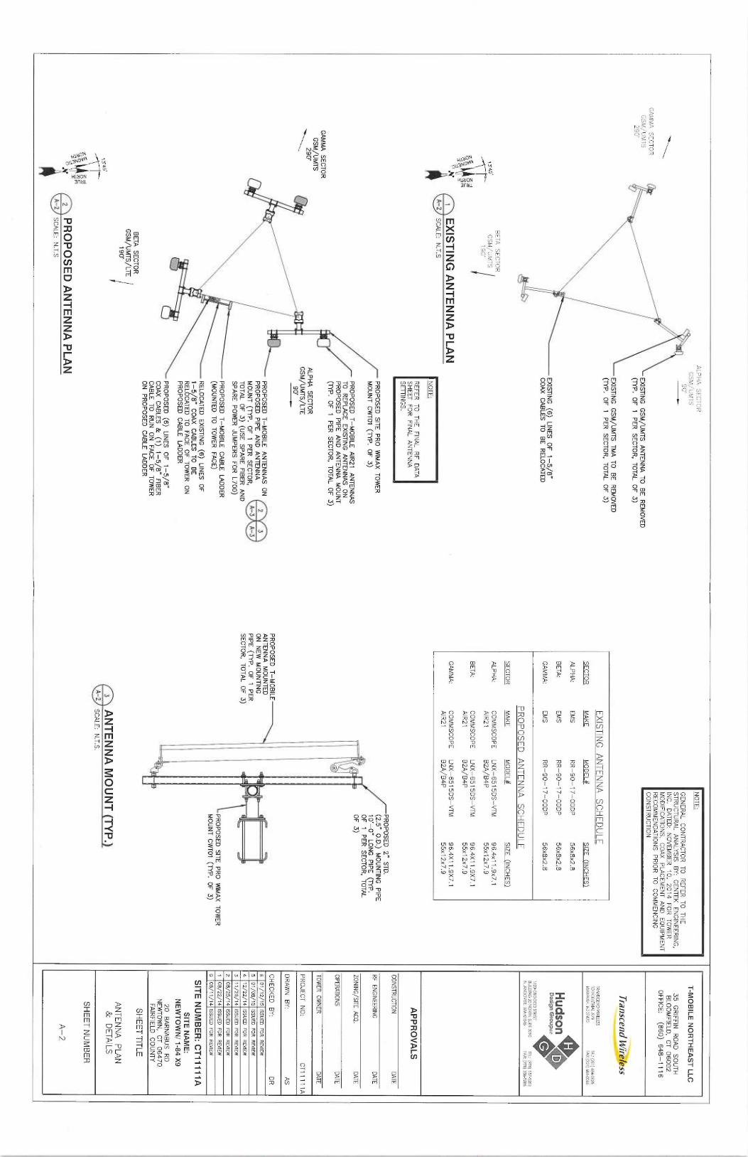
"N ~ EXISTING ANTENNA PLAN
A-Z
SCALE: N.T.S
NOTE:
REFER TO THE FINAL
RF DATA
SHEET FOR FINAL
ANTENNA
SETTINGS.
GAMMA SECTOR
GSM/UMTS
~\90'
BETA SECTOR
GSM/UMTS/LTE
190'
134 5
o=
o~
~~ =m~] PROPOSED ANTENNA PLAN
A-2 SCALE: N.T.S
PROPOSED SITE P
RO AMAX TOWER
MOUNT CWT01 (TYP. OF 3)
PROPOSED T—MOBILE AIR21
ANTENNAS
TO REPLACE EXISTING
ANTENNAS ON
PROPOSED PIPE AND ANTENNA MOUNT
(TYP. OF 1 PER SECTOR, TOTAL OF 3)
HA SECTOR
I/UMTS/LTE
90'
PROPOSED T—MOBILE ANTENNAS ON
2 3
PROPOSED PIPE AND ANTENNA
MOUNT (TYP. OF 1
PER SECTOR,
A-3
A-3
TOTAL OF 3) (USE SPARE FlBER AND
SPARE POWER JUMPERS FOR L700)
PROPOSED T—MOBILE CABLE LADDER
(MOUNTED TO TOWER FACE)
RELOCATED EXISTING (
6) LINES OF
1-5/8" COAX CABLES TO BE
RELOCATED TO FACE OF TOWER ON
PROPOSED CABLE LADDER
PROPOSED (6) LINES OF 1-5/8"
COAX CABLES & (1) 1-5/8" FIBER
CABLE TO RUN ON FACE OF TOWER
ON PROPOSED CABLE LADDER
NOTE:
GENERAL CONTRACTOR TO REFER TO THE
STRUCTURAL ANALYSIS BY: CENTEK ENGINEERING,
INC. DATED: NOVEMBER 10, 2014 FOR TOWER
MODIFICATIONS, COAX PLACEMENT AND EQUIPMENT
RECOMMENDATIONS PRIOR TO COMMENCING
CONSTRUCTION
EXISTING ANTENNA SCHEDULE
SECTOR
MAKE
MODEL
SIZE (INCHES)
ALPHA:
EMS
RR-90-17—OODP
56x8x2.8
BETA:
EMS
RR-90-17—OODP
56x8x2.8
GAMMA:
EMS
RR-90-17—OODP
56x8x2.8
PROPOSED ANTENNA SCHEDULE
SECTOR
MAKE
MODEL
SIZE (INCHES
ALPHA:
COMMSCOPE
LNX-6515DS—VTM
96.4x11.9x7.tAIR21
B2A/B4P
SSx12x7.9
BETA:
COMMSCOPE
WX-6515DS—VTM
96.4X11.9X7.1
AIR21 B2A/B4P
55x12x7.9
GAMMA:
COMMSCOPE
LNX-6515DS—VTM
96.4X11.9X7.1
AIR21 62A/64P
55x 12x7.9
PROPOSED T—MOBILE
ANTENNA MOUNTED
ON NEW MOUNl1NG
PIPE (TYP. OF 1
PER
SECTOR, TOTAL OF 33 ANTENNA MOUNT (TYP.)
A-2
SCALE: N.T.S.
PRO AMAX TOWER
TYP. OF 3)
T-MOBILE NORTHEAST LLC
35 GRIFFIN
ROAD SOUTH
BLOOMFIELD, CT 06002
OFFICE: (860) 648-1116
TldDSCERf~ W%CB~ESS
TRANSCEND WIRELESS
101N~U5TRIAL AVE
TEL: (201J 6840055
MAHWAH, NJ 07430
FAX:~201J 684-0066
Hudson4~
Design 6roupuc
1600 05GOOD STREET
BUILDING 20 NORTH, SIlIiE 3090
iEL: (970557-5553N. A
NDOVER, MA 01845
FAX: ~978~ 336-5586
APPROVALS
CONSTRUCTION DATE
RF ENGINEERING
DATE
ZONING~SITE ACQ. DATE
OPERATIONS DATE
TOWER OWNER
DATE
PROJECT N0:
CT11111A
DRAWN BY:
AS
CHECKED BY:
DR
6 01/12/75 ISSUED FOR REVIEW
5 01/08/15 ISSUED FOR REVIEW
4 12/22/14 ISSUED FOR REVIEW
3 17/26/74 ISSUED FOR REVIEW
2 08/25/14 ISSUED FOR REVIEW
1 08/22/14 ISSUED FOR REVIEW
0 OB/11 /14 ISSUED FOR REVIEW
SITE NUMBER: CT11111A
SITE NAME:
NEWTOWN/ 1-84 X9
20 BARNABUS RD
NEWTOWN, CT 06470
FAIRFIELD COUNTY
SHEET TITLE
ANTENNA PLAN
& DETAILS
SHEET NUMBER
A-2
~e.,~„~~~ ~~ STD
JNTING PIPE
IPE (TYP.
TOR, TOTAL
STAINLESS
STEEL
HARDWARE
GROUNDING
TWO HOLE COPPER
COMPRESSION TERMINAL
GROUND BAR
LOCK WASHER,
FLAT WASHER, NP.
(TYP.)
3/8"z1-1/4" HEX
BOLT
NUT, TYP.
GROUND BAR
GROUNDING
EXPOSED BARE COPPER TO BE
CABLE
KEPT TO ABSOLUTE MINIMUM, NO
SECTION "A—A"
INSULATION ALLOWED WITHIN
THE
COMPRESSION TERMINAL (TYPICAL)
NOTE:
1. "DOUBLING UP" OR "STACKING
OF CONNECTION IS
NOT PERMITTED.
2. OXIDE INHIBITING
COMPOUND TO BE USED AT ALL LOCATIONS.
3. CADWELD DOWNLEADS FROM UPPER EGB, LOWER EGB, AND MGB.
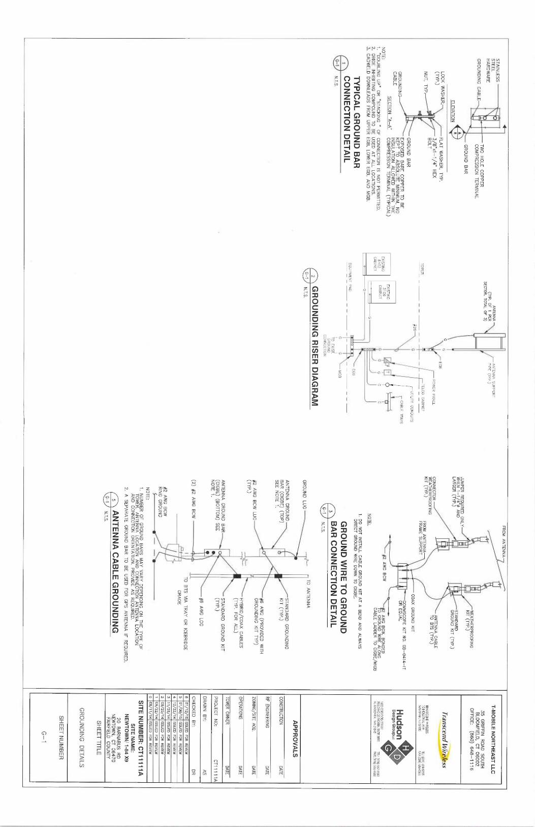
TYPICAL GROUND BAR
~ CONNECTION DETAIL
G-1 N.T.S.
ANTENNA
ANTENNA SUPPORT
(TYP. OF 1
PER
PIPE (1YP.)SECTQR, TOTAL OF 3)
G
~
EGB
POWER PANEL
TOWER
TELCO CABINET
#ZG
~
UTILITY CONDUITS
TRAYS
EXISTING -
7
E 6I102G CABINET
G
GN ~
G
GCABINET
G
o
c
EQUIPMENT PAD
o
EGB
G
G
MGB
TO EXIST.
GROUND
CONNECTION
~ GROUNDING RISER DIAGRAM
G-1 N.T.S.
FROM ANTENNA
A.r
JUMPER REQUIRED
ONLY
WHEN 1-1/4"0 AND
LARGER (TYP.)
CONNECTOR --~
WEATHERPROOFING
KIT (TYP.) FROM ANTENNA
FRAME SUPPORT#2 AWG BCW
NOTE:
STANDARD
GROUND KIT (TYP.)
ANTENNA CABLE
TO BTS (TYP.)
COAX GROUND KIT
—COMMSCOPE KIT N0. G
B-0414—IT
OR EQUAL
AWG BCW, BONDED
0 GROUND WIRE A
LONG
CABLE LADDER TO CIGBE/MIGB
1. DO NOT INSTALL C
ABLE GROUND KIT A
T A BEND AND ALWAYS
DIRECT GROUND WIRE D
OWN TO CIGBE.
GROUND WIRE TO GROUND
~ BAR CONNECTION DETAIL
G-1 N.T.S..
GROUND LUG
TO ANTENNA
ANTENNA GROUND
STANDARD GROUNDING
BAR (CIGBE) (TOP)
KIT (TYP.)
SEE NOTE 1.
~#6 AWG (PROVIDED WITH
#2 AWG BCW LUG
GROUNDING KIT T
YP)
(TYP.)
HYBRID/COAX GABLES
(TYP. FOR ALL)
ANTENNA GROUND BARS
_
STANDARD GROUND KIT
(CIGBE) (BOTTOM) SEE
(TYP.)
NOTE 1.
#6 AWG LOG
(2) #2 AWG BCW
~ TO BTS VIA
TRAY OR ICEBRIDGE
GRADE
#2 AWG BCW
RING GROUND
~~ ~
NOTE:
1. NUMBER OF GROUND BARS MAY VARY DEPENDING ON THE TYPE OF
TOWER. ANTENNA LOCATION AND CONNECTION ANTENNA LOCATION
AND CONNECTION ORIENTATION. PROVIDE AS REQUIRED.
2. A SEPARATE GROUND BAR TO BE USED FOR GPS ANTENNA IF
REQUIRED.
~ ANTENNA CABLE GROUNDING
~`~ N.T.S.
T-MOBILE NORTHEAST LLC
35 GRIFFlN
ROAD SOUTH
BLOOMFIELD, CT 06002
OFFICE: (860) 648-1116
TranscEnd Wire%ss
TRANSCEND WIRELESS101NDU5fRIAL ASE
TEL: ~201J 6840055MAHWAH, NJ W430
FN(:~201~ 684-0066
Hudson4~
design t,'~oupuc
160005GOOD SiREEi O
BUILDING 7A NORTH. SURE 3090 Td: (978) 557-5553
N. ANDOVER, MA O1B45
FAX: (978 33G5586
APPROVALS
CONSTRUCTION DATE
RF ENGINEERING
DATE
ZONING/SITE ACQ. DATE
OPERATIONS DATE
TOWER OWNER
DATE
PROJECT N0;
CT11111A
DRAWN BY:
AS
CHECKED BY:
DR
6 ~t/72/15 ISSUED
FOR REVIEW
5 01/08/75 ISSUED
FOR REVIEW
4 12/22/14 ISSUED
FOR REVIEW
3 11/26/14 ISSUED
FOR REVIEW
2 OB/25~14 ISSUES
FOR REVIEW
1 08/22/14 ISSUES F
OR REVIEW
0 08/11/14 ISSUED
FOR REVIEW
SITE NUMBER: CT11111A
SITE NAME:
NEWTOWN/ 1-84 X
920 BARNABUS RD
NEWTOWN, CT 06470
FAIRFIELD COUNTY
SHEET TITLE
GRQUNDING DETAILS
SHEET NUMBER
G-1

C=NT =1~engineering
Centered on Solutions"`
Structural Analysis andTower Reinforcement R e p o r t
180-ft Existing ROHN SSV Lattice Tower
Proposed T-MobileAntenna Upgrade
T-Mobile Site Ref: CT17171A
20 Barnabas RoadNewtown, CT 06470
CENTEK Project No. 14025.011
Date: November 10, 2014
y5,~ti yRllelidi~~+~
~'t` L,a ~r+ P~1 ~~,P ,i ~*it~, ~}~ r'. ~''..r
~~ ~ f~~ .s.~ v
'+tl ~. ~ ~ r . ~~,
~ — ° ~
~~ t41 ~`si~~~ ~~1
r~ fr f
rts~rt ~~~',.A''.
Prepared for:T-Mobile Towers4 Sylvan Way
Parsippany, NJ 07054
63-2 North Branford Road, Branford, CT 06405 203.88.0580 Fax 203.488.8587 www.CentekEng.com
CENTEK Errgine~!~r~a, ~`~°?r,Structural Analysis - 180-ft ROHN SSV Lattice TowerT-Mobile Antenna Upgrade — CT11117ANewtown, CTNovember 70, 2014
Table of Contents
SECTION 1 —REPORT
■ INTRODUCTION.
■ ANTENNA AND APPURTENANCE SUMMARY.
■ PRIMARY ASSUMPTIONS USED IN THE ANALYSIS.
■ ANALYSIS.
■ TOWER LOADING.
■ TOWER CAPACITY.
■ FOUNDATION AND ANCHORS.
■ CONCLUSION.
SECTION 2 —CONDITIONS 8~ SOFTWARE
■ STANDARD ENGINEERING CONDITIONS.
■ GENERAL DESCRIPTION OF STRUCTURAL ANALYSIS PROGRAM.
SECTION 3 —CALCULATIONS
■ tnxTower INPUT/OUTPUT SUMMARY
■ tnxTower FEED LINE PLAN
■ tnxTower FEED LINE DISTRIBUTION
■ tnxTower DETAILED OUTPUT
■ ANCHOR BOLT ANALYSIS
■ FOUNDATION ANALYSIS
SECTION 4 —DRAWINGS
■ T-1 TITLE SHEET
■ N-1 DESIGN BASIS AND GENERAL NOTES
■ N-2 STRUCTURAL STEEL NOTES
■ MI-1 MODIFICATION INSPECTION REQUIREMENTS
■ S-1 TOWER REINFORCEMENT DETAILS
SECTION 5 —REFERENCE MATERIALS
■ EQUIPMENT CUT SHEETS.
TABLE OF CONTENTS TOC-1
CENTEK ~ngir~ediK~~, d~~c.Structural Analysis - 180-ft ROHN SSV Lattice TowerT-Mobile Antenna Upgrade — CT11111ANewtown, CTNovember 10, 2014
Introduction
The purpose of this report is to summarize the results of the non-linear, P-4 structural analysisof the antenna upgrade proposed by T-Mobile on the existing Northeast Utilities self supportinglattice tower located in Newtown, Connecticut.
The host tower is a 180-ft three legged, tapered steel lattice tower originally designed andmanufactured by UNR-ROHN. The tower geometry and structure member sizes were obtainedfrom a tower mapping report prepared by CSB Communications LLC, dated August 22, 2006and a previous structural analysis and reinforcement design report prepared by CentekEngineering, Inc., project no. 14025.002 (Rev. 2), dated April 9, 2014.
Antenna and appurtenance inventory were obtained from a combination of the aforementionedCentek Engineering, Inc. structural analysis and reinforcement design report and informationfrom T-Mobile.
The existing tower consists of nine (9) tapered steel pipe leg sections conforming to ASTMA572-50..Diagonal lateral support bracing consists of single angle steel sections conforming toASTM A36. All tower connections are bolted. The width of the tower face is 8.56-ft at the topand 24.86-ft at the base.
T-Mobile proposes the removal of three (3) panel antennas and three (3) TMA's and theinstallation of six (6) panel antennas mounted on three (3) proposed mounts. Refer to theAntenna and Appurtenance Summary below for a detailed description of the proposed antennaand appurtenance configuration.
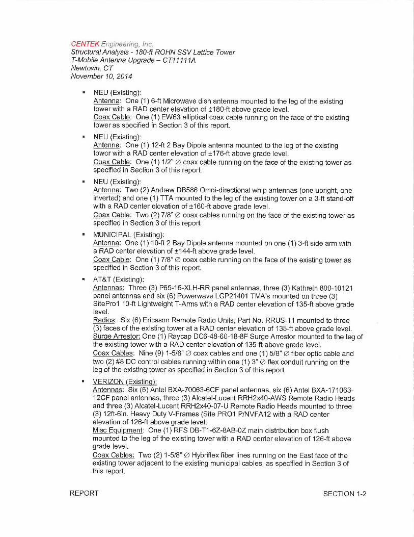
Antenna and Appurtenance Summary
The existing tower supports several communication antennas. The existing and proposed loadsconsidered in the analysis consist of the following:
■ NEU (Existing):Antenna: One (1) RFS PD220 Omni-directional whip antenna pipe mounted to thetop of the existing tower with a RAD center elevation of ±191-ft above grade level.Coax Cable: One (1) 7/8" Q1 coax cable running on the face of the existing tower asspecified in Section 3 of this report.
■ NEU (Existing):Antenna: One (1) 8-ft Omni-directional whip antenna mounted to the top of theexisting tower with a RAD center elevation of ±189-ft above grade level.Coax Cable: One (1) 1/2" ~ coax cable running on the face of the existing tower asspecified in Section 3 of this report.
■ MUNICIPAL (EXISTING):Antenna: One (1) 10-ft 2 Bay dipole antenna mounted to the top of the existingtower with a RAD center elevation of ±188-ft above grade level.Coax Cable: One (1) 1/2" Q~ coax cable running on the face of the existing tower asspecified in Section 3 of this report.
REPORT SECTION 1-1
CENTEK Engineering, Inc.Structural Analysis - 180-ft ROHN SSV Lattice TowerT-Mobile Antenna Upgrade — CT11171ANewtown, CTNovember 10, 2014
■ NEU (Existing):Antenna: One (1) 6-ft Microwave dish antenna mounted to the leg of the existingtower with a RAD center elevation of ±180-ft above grade level.Coax Cable: One (1) EW63 elliptical coax cable running on the face of the existingtower as specified in Section 3 of this report.
■ NEU (Existing):Antenna: One (1) 12-ft 2 Bay Dipole antenna mounted to the leg of the existingtower with a RAD center elevation of ±176-ft above grade level.Coax Cable: One (1) 1/2" ~ coax cable running on the face of the existing tower asspecified in Section 3 of this report.
■ NEU (Existing):Antenna: Two (2) Andrew DB586 Omni-directional whip antennas (one upright, oneinverted) and one (1) TTA mounted to the leg of the existing tower on a 3-ft stand-offwith a RAD center elevation of ±160-ft above grade level.Coax Cable: Two (2) 7/8" ~ coax cables running on the face of the existing tower asspecified in Section 3 of this report.
■ MUNICIPAL (Existing):Antenna: One (1) 10-ft 2 Bay Dipole antenna mounted on one (1) 3-ft side arm witha RAD center elevation of ±144-ft above grade level.Coax Cable: One (1) 7/8" ~ coax cable running on the face of the existing tower asspecified in Section 3 of this report.
■ AT&T (Existing):Antennas: Three (3) P65-16-XLH-RR panel antennas, three (3) Kathrein 800-10121panel antennas and six (6) Powerwave LGP21401 TMA's mounted on three (3)SitePro1 10-ft Lightweight T-Arms with a RAD center elevation of 135-ft above gradelevel.Radios: Six (6) Ericsson Remote Radio Units, Part No. RRUS-11 mounted to three(3) faces of the existing tower at a RAD center elevation of 135-ft above grade level.Surge Arrestor: One (1) Raycap DC6-48-60-18-8F Surge Arrestor mounted to the leg ofthe existing tower with a RAD center elevation of 135-ft above grade level.Coax Cables: Nine (9) 1-5/8" Qs coax cables and one (1) 5/8" ~ fiber optic cable andtwo (2) #8 DC control cables running within one (1) 3" Qs flex conduit running on theleg of the existing tower as specified in Section 3 of this report.
■ VERIZON (Existing):Antennas: Six (6) Antel BXA-70063-6CF panel antennas, six (6) Antel BXA-171063-12CF panel antennas, three (3)Alcatel-Lucent RRH2x40-AWS Remote Radio Headsand three (3)Alcatel-Lucent RRH2x40-07-U Remote Radio Heads mounted to three(3) 12ft-bin. Heavy Duty V-Frames (Site PR01 P/NVFA12 with a RAD centerelevation of 126-ft above grade level.Misc Equipment: One (1) RFS DB-T1-6Z-8AB-OZ main distribution box flushmounted to the leg of the existing tower with a RAD center elevation of 126-ft abovegrade level.Coax Cables: Two (2) 1-5/8" QS Hybriflex fiber lines running on the East face of theexisting tower adjacent to the existing municipal cables, as specified in Section 3 ofthis report.
REPORT SECTION 1-2
CENTEK ~ne~i~aeerin~~ ~r~ ~.Structural Analysis - 180-ft ROHN SSV Lattice TowerT-Mobile Antenna Upgrade — CT11171ANewtown, CTNovember 10, 2014
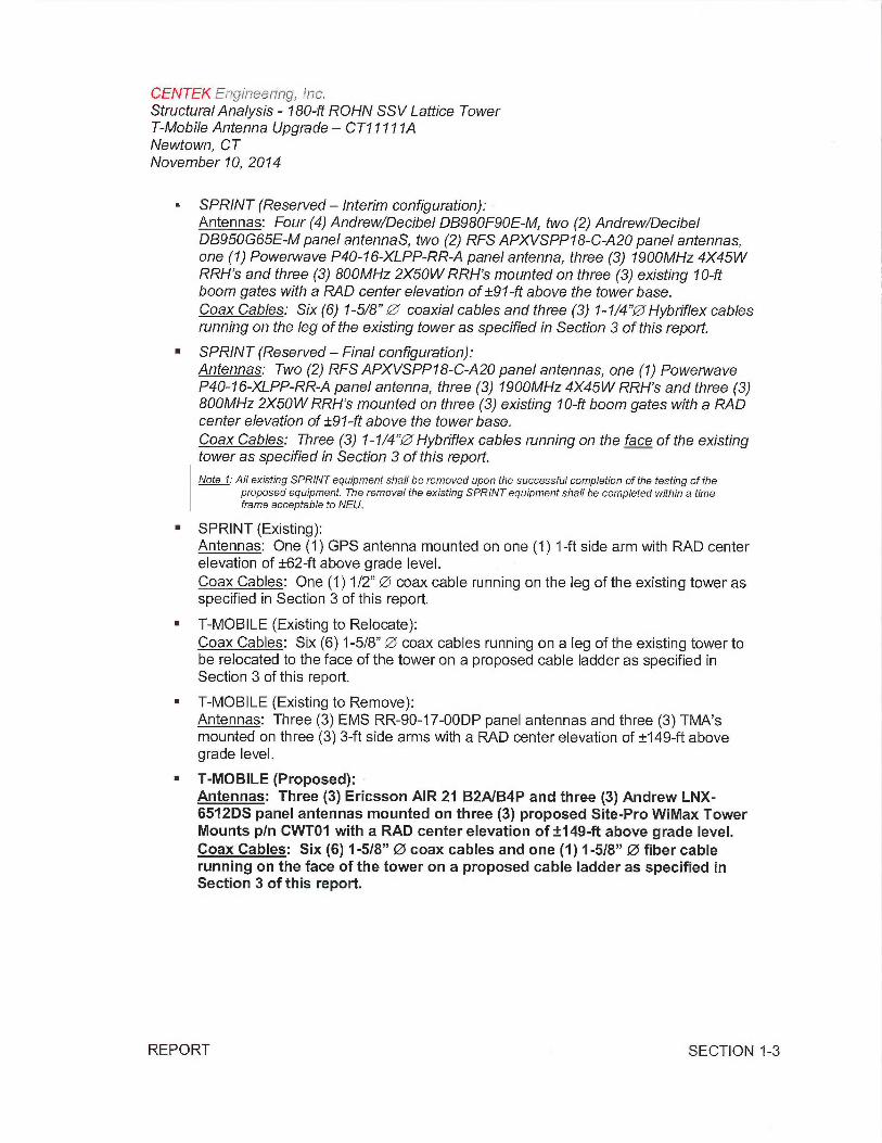
■ SPRINT (Reserved —Interim configuration):Antennas: Four (4) Andrew/Decibel D8980F90E-M, iwo (2) Andrew/DecibelD8950G65E-M panel antennas, two (2) RFS APXVSPP18-C A20 panel antennas,one (1) Powerwave P40-16-XLPP-RR A panel antenna, three (3) 1900MHz 4X45WRRH's and three (3) 800MHz 2X50W RRH's mounted on three (3) existing 70-ftboom gates with a R,4D center elevation of ±91-ft above the tower base.Coax Cables: Six (6) 1-5/8" ~" coaxial cables and three (3) 1-1/4"~ Hybriflex cablesrunning on the leg of the existing tower as specified in Section 3 of this report.
■ SPRINT (Reserved —Final configuration):Antennas: Two (2) RFS APXVSPP18-C-A20 panel antennas, one (1) PowerwaveP40-16-XLPP-RR-A panel antenna, three (3) 1900MHz 4X45W RRH's and three (3)800MHz 2X50W RRH's mounted on three (3) existing 10-ft boom gates with a R,4Dcenter elevation of ±97-ft above the tower base.Coax Cables: Three (3) 1-1/4'Pl Hybriflex cables running on the face of the existingtower as specified in Section 3 of this report.
Note 1: All existing SPRINT equipment shall be removed upon the successful completion of the testing of theproposed equipment. The removal the existing SPRINT equipment shall be completed within a timeframe acceptable to NEU.
■ SPRINT (Existing):Antennas: One (1) GPS antenna mounted on one (1) 1-ft side arm with RAD centerelevation of ±62-ft above grade level.Coax Cables: One (1) 1/2" ~ coax cable running on the leg of the existing tower asspecified in Section 3 of this report.
■ T-MOBILE (Existing to Relocate):Coax Cables: Six (6) 1-5/8" ~ coax cables running on a leg of the existing tower tobe relocated to the face of the tower on a proposed cable ladder as specified inSection 3 of this report.
■ T-MOBILE (Existing to Remove):Antennas: Three (3) EMS RR-90-17-OODP panel antennas and three (3) TMA'smounted on three (3) 3-ft side arms with a RAD center elevation of ±149-ft abovegrade level.
■ T-MOBILE (Proposed):Antennas: Three (3) Ericsson AIR 21 B2A/B4P and three (3) Andrew LNX-6512DS panel antennas mounted on three (3) proposed Site-Pro WiMax TowerMounts p/n CWT01 with a RAD center elevation of ±149-ft above grade level.Coax Cables: Six (6) 1-5/8" Q1 coax cables and one (1) 1-5/8" QJ fiber cablerunning on the face of the tower on a proposed cable ladder as specified inSection 3 of this report.
REPORT SECTION 1-3
CENTEK ~nc~inee!;r~rc~, Inc,Structural Analysis - 180-ft ROHN SSV Lattice TowerT-Mobile Antenna Upgrade — CT11111ANewtown, CTNovember 10, 2014
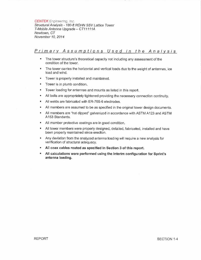
Primary Assumptions Used in the Analysis
■ The tower structure's theoretical capacity not including any assessment of thecondition of the tower.
■ The tower carries the horizontal and vertical loads due to the weight of antennas, iceload and wind.
■ Tower is properly installed and maintained.
■ Tower is in plumb condition.
■ Tower loading for antennas and mounts as listed in this report.
■ All bolts are appropriately tightened providing the necessary connection continuity.
■ All welds are fabricated with ER-70S-6 electrodes.
■ All members are assumed to be as specified in the original tower design documents.
■ All members are "hot dipped" galvanized in accordance with ASTM A123 and ASTMA153 Standards.
■ All member protective coatings are in good condition.
■ All tower members were properly designed, detailed, fabricated, installed and havebeen properly maintained since erection.
■ Any deviation from the analyzed antenna loading will require a new analysis forverification of structural adequacy.
■ All coax cables routed as specified in Section 3 of this report.
■ All calculations were performed using the interim configuration for Sprint'santenna loading.
REPORT SECTION 1-4
CENTEK Ena~~aeerit~c~, lac.Structural Analysis - 180-ft ROHN SSV Lattice TowerT-Mobile Antenna Upgrade — CT11171ANewtown, CTNovember 10, 2074
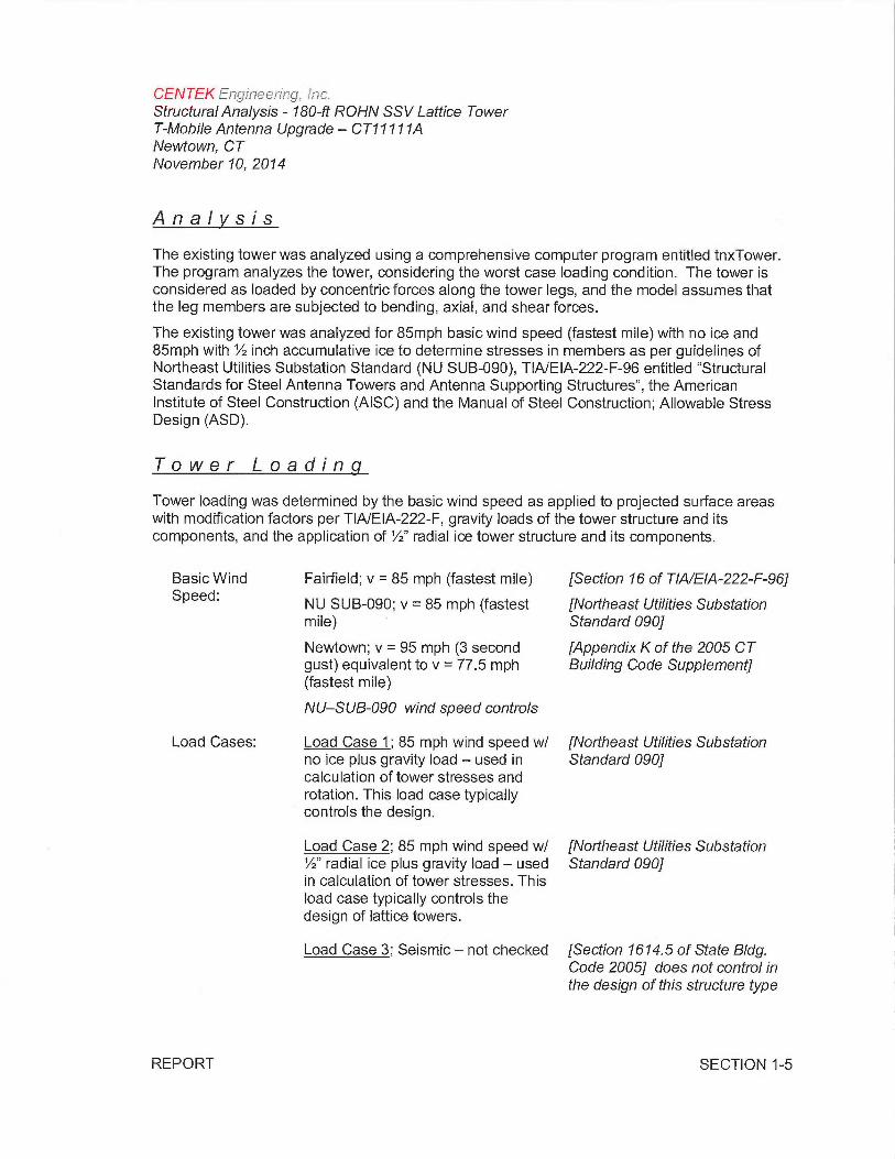
Analysis
The existing tower was analyzed using a comprehensive computer program entitled tnxTower.The program analyzes the tower, considering the worst case loading condition. The tower isconsidered as loaded by concentric forces along the tower legs, and the model assumes thatthe leg members are subjected to bending, axial, and shear forces.
The existing tower was analyzed for 85mph basic wind speed (fastest mile) with no ice and85mph with'/z inch accumulative ice to determine stresses in members as per guidelines ofNortheast Utilities Substation Standard (NU SUB-090), TIA/EIA-222-F-96 entitled "StructuralStandards for Steel Antenna Towers and Antenna Supporting Structures", the AmericanInstitute of Steel Construction (AISC) and the Manual of Steel Construction; Allowable StressDesign (ASD).
Tower Loading
Tower loading was determined by the basic wind speed as applied to projected surface areaswith modification factors per TIA/EIA-222-F, gravity loads of the tower structure and itscomponents, and the application of/2" radial ice tower structure and its components.
Basic Wind Fairfield; v = 85 mph (fastest mile) (Section 16 of TIA/EIA-222-F-96]Speed:
NU SUB-090; v = 85 mph (fastest (Northeast Utilities Substationmile) Standard 090]
Newtown; v = 95 mph (3 second (Appendix K of the 2005 CTgust) equivalent to v = 77.5 mph Building Code Supplement](fastest mile)
NU—SUB-090 wind speed controls
Load Cases: Load Case 1; 85 mph wind speed w/ (Northeast Utilities Substationno ice plus gravity load —used in Standard 090]calculation of tower stresses androtation. This load case typicallycontrols the design.
Load Case 2; 85 mph wind speed w/ (Northeast Utilities Substation'/z" radial ice plus gravity load —used Standard 090]in calculation of tower stresses. Thisload case typically controls thedesign of lattice towers.
Load Case 3; Seismic —not checked (Section 1614.5 of State Bldg.Code 2005] does not control inthe design of this structure type
REPORT SECTION 1-5
CENTEK ~nc~rr7eer~rrg, fr~c.Structural Analysis - 180-ft ROHN SSV Lattice TowerT-Mobile Antenna Upgrade — CT11111ANewtown, CTNovember 70, 2014
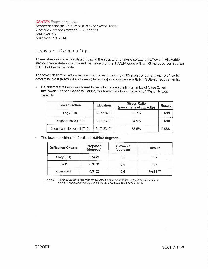
Tower Capacity
Tower stresses were calculated utilizing the structural analysis software tnxTower. Allowablestresses were determined based on Table 5 of the TIA/EIA code with a 1/3 increase per Section3.1.1.1 of the same code.
The tower deflection was evaluated with a wind velocity of 85 mph concurrent with 0.5" ice todetermine twist (rotation) and sway (deflection) in accordance with NU SUB-90 requirements.
• Calculated stresses were found to be within allowable limits. In Load Case 2, pertnxTower "Section Capacity Table", this tower was found to be at 84.9% of its totalcapacity.
Tower Section Elevation Stress Ratio Result(percentage of capacity)
Leg (T10) 3'-0"-23'-0" 78.7% PASS
Diagonal Bolts (T10) 3'-0"-23'-0" 84.9% PASS
Secondary Horizontal (T10) 3'-0"-23'-0" 83.5% PASS
■ The tower combined deflection is 0.5462 degrees.
Deflection Criteria Proposed Allowable Result(degrees) (degrees)
Sway (Tilt) 0.5449 0.5 n/a
Twist 0.0370 0.5 n/a
Combined 0.5462 0.5 PASS ~2~
Note 2: Tower deflection is less than the previously approved deflection of 0.5564 degrees per thestructural report prepared by Centek job no. 74025.002 dated April 9, 2014.
REPORT SECTION 1-6
CENTEK~a~grr~e~rFna, o~?c,Structural Analysis - 180-ft ROHN SSV Lattice TowerT-Mobile Antenna Upgrade — CT11111ANewtown, CTNovember 10, 2014
Foundation and Anchors
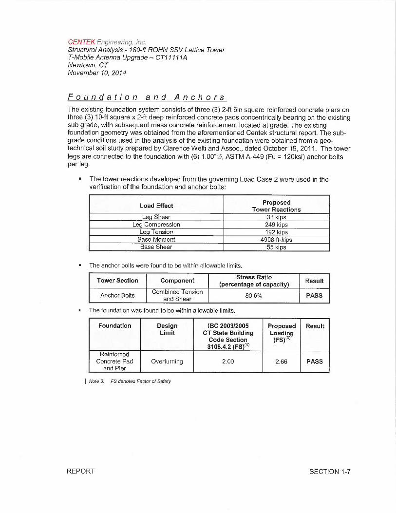
The existing foundation system consists of three (3) 2-ft bin square reinforced concrete piers onthree (3) 10-ft square x 2-ft deep reinforced concrete pads concentrically bearing on the existingsub grade, with subsequent mass concrete reinforcement located at grade. The existingfoundation geometry was obtained from the aforementioned Centek structural report. The sub-grade conditions used in the analysis of the existing foundation were obtained from a geo-technical soil study prepared by Clarence Welti and Assoc., dated October 19, 2011. The towerlegs are connected to the foundation with (6) 1.00"QS, ASTM A-449 (Fu = 120ksi) anchor boltsper leg.
■ The tower reactions developed from the governing Load Case 2 were used in theverification of the foundation and anchor bolts:
Load Effect ProposedTower Reactions
Leg Shear 31 kipsLe Compression 249 kips
Leg Tension 192 kipsBase Moment 4908 ft-kipsBase Shear 55 kips
■ The anchor bolts were found to be within allowable limits.
Tower Section Component Stress Ratio Result(percentage of capacity)
Anchor Bolts Combined Tension
g0.6% PASSand Shear
■ The foundation was found to be within allowable limits.
Foundation Design IBC 2003/2005 Proposed ResultLimit CT State Building Loading
Code Section (FS)~3~3108.4.2 (FS)~4~
ReinforcedConcrete Pad Overturning 2.00 2.66 PASS
and Pier
Note 3: FS denotes Factor of Safety
REPORT SECTION 1-7
CENTEK ~rrg~ir~eeri~~g, dr~c.Structural Analysis - 180-ft ROHN SSV Lattice TowerT-Mobile Antenna Upgrade — CT11711ANewtown, CTNovember 10, 2014
Conclusion
This analysis shows that the subject tower with the proposed reinforcement detailed insection 4 of this report is adequate to support the proposed modified antenna configuration.
The analysis is based, in part, on the information provided to this office by T-Mobile. If theexisting conditions are different than the information in this report, Centek Engineering, Inc.must be contacted for resolution of any potential issues.
Please feel free to call with any questions or comments.
Respectfully Submitted by:
_~ ~ ~~
Timothy J. Lynn, PEStructural Engineer
~ ~Sti~Y J ~r r
r ~~ ~ ?~ `~ --1~i_~ .; ~ v_ ~ `~:
~ No. Z9J36 ,L41
J :~~~ {~~''~ iJ Sir ,,"C~'`;~
f °~~~r~i4~~.$m r~~ ti°t
ti~`~d/!911i3~ti~'~~
REPORT SECTION 1-8
CENTEK Er~gi~~eerinc~, lrac.Structural Analysis - 780-ft ROHN SSV Lattice TowerT-Mobile Antenna Upgrade — CT17171ANewtown, CTNovember 10, 2014
Standard Conditions for Furnishing ofProfessional Engineering Services onExisting Structures
All engineering services are performed on the basis that the information used is current andcorrect. This information may consist of, but is not necessarily limited to:
■ Information supplied by the client regarding the structure itself, its foundations, the soilconditions, the antenna and feed line loading on the structure and its components, orother relevant information.
■ Information from the field and/or drawings in the possession of Centek Engineering, Inc.or generated by field inspections or measurements of the structure.
■ It is the responsibility of the client to ensure that the information provided to CentekEngineering, Inc. and used in the performance of our engineering services is correct andcomplete. In the absence of information to the contrary, we assume that all structureswere constructed in accordance with the drawings and specifications and are in an un-corroded condition and have not deteriorated. It is therefore assumed that its capacityhas not significantly changed from the "as new" condition.
■ All services will be performed to the codes specified by the client, and we do not imply tomeet any other codes or requirements unless explicitly agreed in writing. If wind and iceloads or other relevant parameters are to be different from the minimum valuesrecommended by the codes, the client shall specify the exact requirement. In theabsence of information to the contrary, all work will be performed in accordance with thelatest revision of ANSI/ASCE10 &ANSI/EIA-222
■ All services performed, results obtained, and recommendations made are in accordancewith generally accepted engineering principles and practices. Centek Engineering, Inc.is not responsible for the conclusions, opinions and recommendations made by othersbased on the information we supply.
REPORT SECTION 2-1
CENTEK Engft~eering, Fr7c.Structural Analysis - 180-ft ROHN SSV Lattice TowerT-Mobile Antenna Upgrade — CT17171ANewtown, CTNovember 10, 2074
GENERAL DESCRIPTION OF STRUCTURALANALYSIS PROGRAM
tnxTower, is an integrated structural analysis and design software package for Designedspecifically for the telecommunications industry, tnxTower, formerly RISA Tower, automatesmuch of the tower analysis and design required by the TIA/EIA 222 Standard.
tnxTower Features:
■ tnxTower can analyze and design 3-and 4-sided guyed towers, 3-and 4-sided self-supporting towers and either round or tapered ground mounted poles with or withoutguys.
■ The program analyzes towers using the TIA-222-G (2005) standard or any of theprevious TIA/EIA standards back to RS-222 (1959). Steel design is checked using theAISC ASD 9th Edition or the AISC LRFD specifications.
■ Linear and non-linear (P-delta) analyses can be used in determining displacements andforces in the structure. Wind pressures and forces are automatically calculated.
■ Extensive graphics plots include material take-off, shear-moment, leg compression,displacement, twist, feed line, guy anchor and stress plots.
■ tnxTower contains unique features such as True Cable behavior, hog rod take-up,foundation stiffness and much more.
REPORT SECTION 2-2
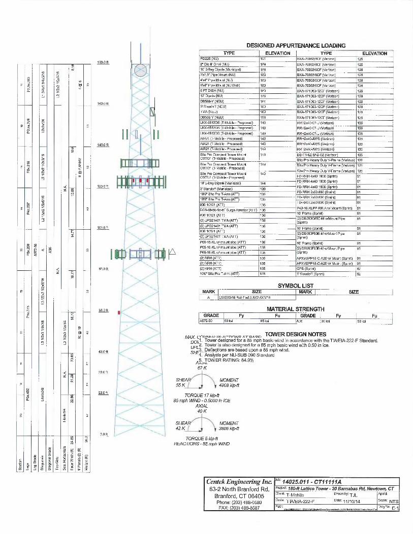
DESIGNED APPURTENANCE LOADING
m n ~ry ~ ~ n
~ b NH m ~ aa
r aN
Na
n~ ~ aN {p
N tp
a ~ (c~
~ W
z ~N
~ ~
N
a c~
a
C ~ ~ ¢ ~ °~a ¢ a
4z
'o
xa ci
a
'~ ~"
C M ~1 a~ o
N€ ~
4z
N
~ ~N ~
V
Xa ~ i~'
a
~ paJ
v nN
~ Fes' C~~'
m C7 Q r ~0 _ _ ~ .o a _ Y
o ~ ~ x 3J c ~a
y~~ o v t'- in ii u 3
103.0 ft
163_0 ft
143.0 f[
1?3.0 ft
703.0 ft
83.0 ft
63A ft
43.0 ft
33.0 ft
23.0 ft
3.0 ft
SYMBOL LISTMARK SIZE MARK SIZEA L3X3X3/16 Relrrf WIL2.SX2.5X3/1fi
MATERIAL STRENGTHGRADE Fy Fu GRADE Fy Fu
A572-50 50 ksl 65 ksi A36 36 ksl 58 ksi
~-no~~~o ocnr~nnn~c nTQnc~. TOWER DESIGN NOTESDOLE- Tower designed for a 85 mph basic wind in accordance with the TIA/EIA-222-F Standard.UPLZ' Tower is also designed fora 85 mph basic wind with 0.50 in ice.
3. Deflections are based upon a 85 mph wind.SHE4. Analysis per NU-SUB-090 Standard~5_rTOW ER RATING: 84.9%
62 K
SHEAh' \ MOMENT55 K~~~ ` 4908 kip-ft
TORQUE 17 kip-fr85 mph WIND - 0.5000 in ICE
AXIAL40 K
SHEA~ MOMENT42 K~ 1~ 3806 kip-ft
TORQUE 5 kip-ftREACTIONS - 85 mph WIND
TYPE ELEVATION TYPE ELEVATIONPD220 (NU) 791 BXA-70~fi3/6CF (Verizon) 126
2' Dia B' Omm (NU) 189 BXA-70D63IfiCF (Verizon) 126
70' 2-Bay Dipole (Munidpal) 188 BXA-70063/6CF (Verimn) 12fi
3'X2.5' Pipe Mount (NU) 183 BXA-700631fiCF (Verimn) 12fi
4k4" Pipe Mount (NU) 183 BXA-70063/6CF (Verimn) 126
6k4" Pipe Mount (NU Dlsh) 180 BXA-7006316CF (Verimn) 126
6 FT DISH (NU) 180 BXA-1770fi&12CF (Verizon) 126
17 Dipole (NU) 176 8XA-171063-12CF (Vedzon) 126
DB586-Y (NEU) 164 BXA-17106&12CF (Vedmn) 126
3' Standoff (NEU) 160 BXA-171063-12CF (Ved7An) 726
TMA (N EU) 1fi0 BXA-171063-12CF (Verizon) 126
DB58CrY (NEU) 156 BXA-771063-12CF (Veriwn) 126
LMC~51?DS (f-Mobile-Proposed) 149 RRHDc40-07-U (Verizon) 726
LNX~51?DS (f-Mobile-Proposed) 149 RRHDc46-07-U (Verizon) 126
LM(~512DS (T-Mo611e-Proposed) 149 RRHDc40-07-U (Verizon) 126
AIR21 (f-Mobile-Proposed) 149 RRHDc40.AW5 (Verimn) 126
AIR21 (f-0Ao6ile-Proposed) 149 RRH9c40-AWS (Verizon) 126
NR21 (T-Mobile-Proposed) 149 RRH2c40 AW5(Yerimn) 126
Site Pro Compact Tourer Mount 149 DB-T1-6Z-BAB-~Z (Verlmn) 126CWT01 (T-Moblle-Proposed) Site Pro Heavy Duty V-Frame (Verizon) 726Site Pm Compact Tower Mount 149 Site Pro Heavy Dury V-Frame (Verizon) 72fiCWT~1 (T-Mobile- Proposed)
Site Pro Heary Dury V-Frame (Verizon) 726Site Pm Compact Tourer Mount 749
F0.RRH 4x4()1900 (Spoof) 91CNlT01 (T-Mobile-Proposed)
10' 2$ay Dipole (Munidpal) 7qq F0.RRH 4~c40 1900 (Sprits) 91
3' S~ndofl (Mwicipal) egg F0.RRH 4x40 1900 (Sprits) 91
10'6" Site Pro T-Artn (ATT) X35 F~RH ~d0 800 (Spriflt) 91
10'6" Site Pro T-Arm (ATT) 735 F~RH 2~d0 800 (Spflnt) 91
BOD 10121 (ATT) 135 F0.RRH 2x50 800 (Spritrt) 91
DC6-08-60-18-8F Surga Arrestor (A'f~ 135 P40-16-XLPP-RR-Aw/Mount (Sprint) 91
B00 10121 (ATT) 135 70' Freme (Sprirrt) 91
(2) LPG21401 TMA (ATT) 135 (2) D0950G65E-M wlMount Plpe 91(Spent)
(2) LPG21401 TMA (ATT) 135 10' Frame (Sprird) 91
800 10121 (ATE 135 (2) DB980F90E-M wlMoisit Pipe 91
(2) IPG21401 TMA (ATT) 135 (SprirR)
P6S1GXL w/ mourn pipe (ATT) 135 10' Frame (SprirR) 91P65-16-XL wl mount pipe (ATT) 135 (2) D8980F90E-M wRvtount Pipe 91P65-1GXL w/ mount pipe (ATT) 135 (SprirR)
(2) RRH (ATT) 135 APXVSPPIB-C-A20 w/ Mourn (SprirR) 91
(2) RRH (ATT) 135 APXVSPPIB-C-A20 w/ Moum (Sporn) 91
(2) RRH (ATT) 135 GPS (Sprirrt) fit
1~'6" Site Pro T-Arm (ATT) 135 7' Standoff (SprirR) 62
Centek Engineering InG °b' 14025.011- CT11111A63-2 North Branford Rd. P~OJ8L~:180-ft Lattice Tower-20Barnabas Rd, Newtown, CT
Branford, CT 06405 Client: T-Mobile ~~`vney'TJL APP'd'
Pho~2: (203) 488-0580 Ode' TIAIEIA-222-F ~~e' 11/10/14 S̀ ~e' NTSFAX: 203 488-8587 Path: Dwg No. E_~
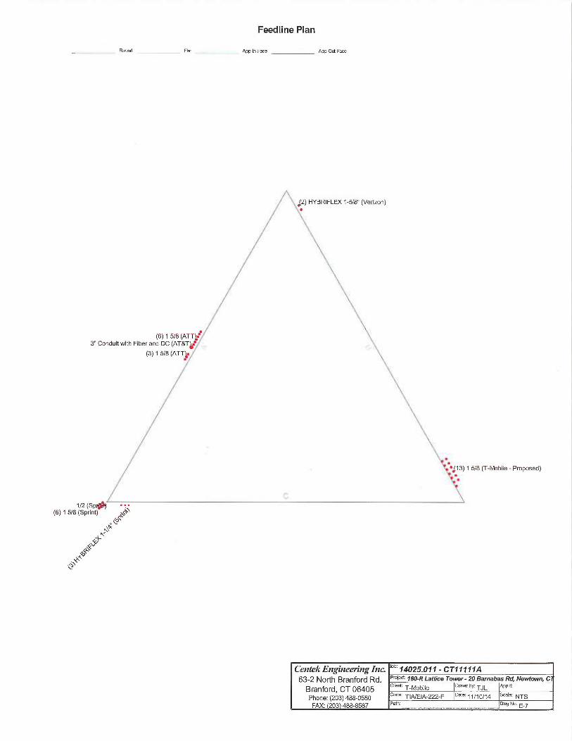
Feedline Plan
Round Flat App In Face App Ou[ Face
1 5/8 (T-Mobile -Proposed)
(6) 1 5/8
.. ̀c~~^\~`
~^~~~
~~`1~
Centek Engineering InG oe~ 14025.011- CT11111A63-2 North Branford Rd. PfOfe~ ~8o-ftLafticeTower-20BamabasRd,Newtown,C
Branford, CT 06405 Cliene T-Mobile orawnhy:T~L aPP~a:
Phone: (203) 488-0580 Code: TIA/EIA-222-F Date:. ~~10/14 Scale: NTS
FAX: 203 488-8587 Path Dwg No.._.~..m.._........_..~..~ ~_._~._.___..._....w...,..__e. E-7
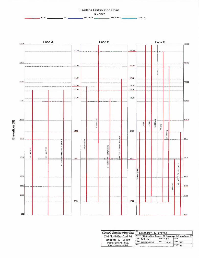
Feedline Distribution Chart3' -183'
Round Flat App In Face App Out Face Truss Leg
.~
0
dw
Centek Engineering Inc °b' 14025.011- CT11177A63-2 North BI'8nfo~d Rd. Pr°~eL~:180-ftLaffice Tower-20Barnabas Rd,NewEown,C
Branford, CT 06405 ciiern: T-Mobile °ra"'" bY`TJL APP~d
Phone: (203) 488-0580 code: TIA/EIA-222-F oate:11/10/14 scale: NTS
FAX: 203 488-8587 Path: owg No.,._.._..N,.m..,,._...~....tr_._ .r.........,._~..._s~ E-7
Face A Face B Face C
Job Page
~~~~OWey' 14025.011 - CT11111A 1 of 35
CentekEngineeringlnc. Project Date
63-zNorahBYanfo~~ana. 180-ft Lattice Tower- 20 Barnabas Rd, Newtown, CT 12:12:26 11/10/14
Branford, CT 06405 Client Designed byPhone: (203)488-0580 T-Mobile TJLFAX. (203) 488-8587
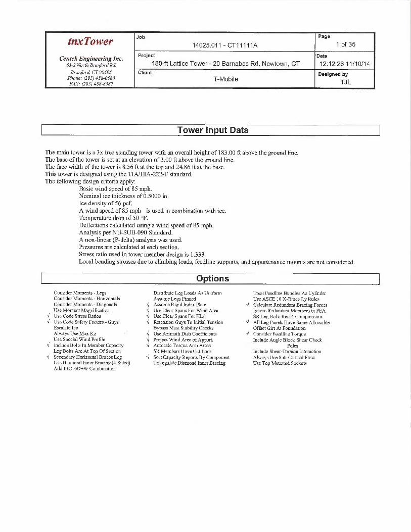
Tower Input Data
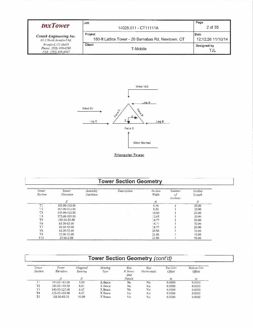
The main tower is a 3x free standing tower with an overall height of 183.00 ft above the ground line.The base of the tower is set at an elevation of 3.00 ft above the mound line.The face width of the tower is 8.56 $ at the top and 24.86 ft at the base.This tower is designed using the TIA/EIA-222-F standard.The following design criteria apply.
Basic wind speed of 85 mph.Nominal ice thiclaiess of 0.5000 in.Ice density of 56 pcf.A wind speed of 85 mph is used in combination with ice.Temperature drop of 50 °F.Deflections calculated using a wind speed of 85 mph.Analysis per NLT-SUB-090 Standard.Anon-linear (P-delta) analysis was used.Pressures are calculated at each section.Stress ratio used in tower member design is 1.333.Local bending stresses due to climbing loads, feedline supports, and appurtenance mounts are not considered.
Options
Consider Moments -LegsConsider Moments -HorizontalsConsider Moments -DiagonalsUse Moment MagnificarionUse Code Stress RatiosUse Code Safety Factors -GuysEscalate. IceAlways Use Max KzUse Special Wind ProfileInclude Bolts In Member CapacityLeg Bolts Are At Top Of SecrionSecondary Horizontal Braces LegUse Diamond Inner Bracing (4 Sided)Add IBC .6D+W Combination
Distribute Leg Loads As UniformAssume Legs PinnedAssume Rigid Index Plate.Use Clear Spans For Wind AreaUse Clear Spans For KLh
~ Retension Guys To Initial TensionBypass Mast Stability Checks
~ Use Azimuth Dish Coefficients~ Project Wind Area ofAppurt.~ Autocalc Torque Arm Areas
SR Members Have Cut Ends~ Sort Capacity Reports By Component
Triangulate Diamond Inner Bracing
Treat Feedline Bundles As CylinderUse ASCE 10 X-Brace Ly RulesCalculate Redundant Bracing ForcesIgnore Redundant Members in FEASR Leg Bolts Resist CompressionAll Leg Panels Have Same AllowableOffset Girt At FoundationConsider Feedline TorqueInclude Angle Block Shear Check
PolesInclude Shear-Torsion InteractionAlways Use Sub-Critical FlowUse Top Mounted Sockets
Job Page
t~~~OWeY 14025.011 - CT11111A 2 of 35
Centek Engineering Inc. Project Date
63-zNo~-rhBYa~fo~~axa. 180-ft Lattice Tower- 20 Barnabas Rd, Newtown, CT 12:12:26 11/10/14Branford, CT 06405 Client Designed by
Phone: (203) 488-0580 T-Mobile TJLFAX (203) 488-8587
Wind 180
~ Lea A
Wind 90 T
~ ~~e' dPN~ e
Leg C Z ~_
Face C
Wind Normal
Triangular Tower
Tower Section Geometry
Tower Towe~~ Assembly Description Section Number SectionSection Elevation Database Width of Length
Sections
T1 183.00-163.00 8.56 1 20.00T2 163.00-143.00 8.56 1 20.00T3 143.00-123.00 10.60 1 20.00T4 123.00-103.00 12.68 1 20.00TS 103.00-83.00 14.77 1 20.00T6 83.00-63.00 16.77 1 20.00T7 63.003.00 18.77 1 20.00T8 43.00-33.00 20.86 1 10.00T9 33.00-23.00 21.86 1 10.00T10 23.00-3.00 22.86 1 20.00
Tower Section Geometry (cont'd)
Tower Tower Diagonal Bracing Has Has Toy Girt Bottom GirtSection Elevation Syacing Type KBrace Horizontals Offset Offset
Endft ft Panels zn in
T1 183.00-163.00 5.00 XBrace No No 0.0000 0.0000T2 163.00-143.00 6.67 X Brace No No 0.0000 0.0000T3 143.00-123.00 6.67 X Brace No No 0.0000 0.0000T4 123.00-103.00 6.67 X Brace No No 0.0000 0.0000TS 103.00-83.00 10.00 X Brace No No 0.0000 0.0000
tnxTowe~ J°b Page
14025.011 - CT11111A 3 of 35
Centek Engineering Inc. Project Date
63-zNol~rha,•anfoYana. 180-ft Lattice Tower - 20 Barnabas Rd, Newtown, CT 12:12:26 11/10/14Branford, CT 06405 Client Designed by
Phone: (203) 488-0580 T-MobileFAX. (203) 488-8587 TJ L
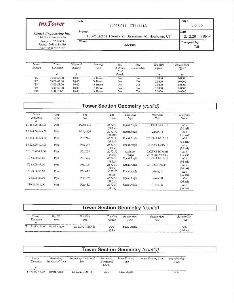
---Towe~~ Tower Diagonal B~ acing Has Has Top Girt Bottom Gi~~tSection Elevation Spacing Type KBrace Horizontals Offset Offset
Endft ft Panels in in
T6 83.00-63.00 10.00 X Brace No No 0.0000 0.0000T7 63.00-43.00 10.00 X Brace No Yes 0.0000 0.0000T8 43.00-33.00 10.00 X Brace No No 0.0000 0.0000T9 33.00-23.00 10.00 X Brace No No 0.0000 0.0000T10 23.00-3.00 10.00 XBrace No Yes 0.0000 0.0000
Tower Section Geometry (cont'd)
Tower Leg Leg Leg Diagonal Diagonal DiagonalElevation Type Size Grade Type Size Grade
Tl 183.00-163._00 Pipe P2Sx.203 A572-50 Equal Angle Ll 3/4x1 3/4x3/16 A36(50 ksi) (36 ksi)
T2163.00-143.00 Pipe P2.Sx276 A572-50 Equal Angle L2~x1/4 .A36(50 ksi) (36 ksi)
T3 143.00-123.00 Pipe P3x.216 A572-50 Equal Angle L2 1/21c2 1/2x3116 A36(50 ksi) (36 ksi)
T4 123.00-103.00 Pipe P4x337 A572-50 Equal Angle L2 1/2Jc2 1/2x5/16 A36(50 ksi) (36 ksi)
TS 103.00-83.00 Pipe PSx258 A572-50 Arbitrary L3X3X3/16 Reinf A36(50 ksi) Shape w/L2.SX2.SX3/16 (36 ksi)
T683.00-63.00 Pipe PSx375 A572-50 Equal Angle L31/2x31/2x5/16 A36(50 ksi) (36 ksi)
T7 63.00-43.00 Pipe PSx.375 .A572-50 Equal Angle L3 1/2ac3 1/2rc3/8 A36(50 ksi) (36 ksi)
T843.00-33.00 Pipe P6x.432 A572-50 Equal Angle L4x41c3/8 A36(50 ksi) (36 ksi)
T9 33.00-23.00 Pipe P6x.432 A572-50 Equal Angle L4x4~c3/8 A36(50 ksi) (36 ksi)
T10 23.00-3.00 Pipe P6x.432 A572-50 Equal Angle L4x4x3/8 A36(50 ksi) (36 ksi)
Tower Section Geometry (cont'd)
Tower Toy Girt Top Girt Top Girt Bottom Girt Bottom Girt Bottom GirtElevation. Type Size Grade Type Size Grade
T1183.00-163.00 Equal Angle L2 1/2ac2 1/2ac3/16 A36 Equal Angle A36(36 ksi) (36 ksi)
Tower Section Geometry (cont'd)~~--- . _v _. -~._~- - _-- ~ == - -= . __~ ~ .__
Tower Secondary Secondary Horizontal Secondary bznerBracing Inner BracingSizeil Inner BracingElevation Horizontal7}~pe Size Horizontal T}~e Grade
Gr^ade
T7 63.00-43.00 Equal Angle L3 1/2ac3 1/2x1/4 A36 Equa] Angle A36
Job Page
tn'x~OY~~~ 14025.011 - CT11111A 4 of 35
Centek Engineering Inc. Project Date
63-zNo~~rt,B,~a~,fo~~ana. 180-ft Lattice Tower- 20 Barnabas Rd, Newtown, CT 12:12:26 11/10/14Branford, CT 06405 Client Designed by
Phone: (203) 488-0580 T-MobileFAX. (203) 488-8587 TJL
Tower Secondary SecondaryHordzoi~tal Secondary Inner Bracing Inner Bracing Size Inner BracingElevation Hordzoratal Tyye Size Horizontal ape Grade
Grade
(36 ksi) (36 ksi)T10 23.00-3.00 Equal Angle L4x4x1/4 A36 Equal Angle A36
(36 ks~) (36 ks~)
Tower Section Geometry (cont'd)
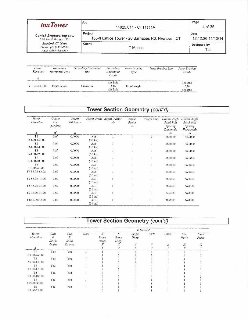
Tower Gusset Gusset Gusset Grade Adjust. Factor Adjust. Weight Mult. Double Angle Double Angle&levation Area Thick~sess Af Factor Stitch Bolt Stitch Bolt
(per face) Ar Spacing SpacingDiagonals Hori>ontals
ft ft' zn in znTl 0.00 0.0000 A36 1 1 1 36.0000 36.0000
183.00-163.00 (36 ksi)T2 0.00 0.0000 A36 1 1 1 36.0000 36.0000
163.00-143.00 (36 ksi)T3 0.00 0.0000 A36 1 1 1 36.0000 36.0000
143.00-123.00 (36 ksi)T4 0.00 0.0000 A36 1 1 1 36.0000 36.0000
123.00-103.00 (36 ksi)TS 0.00 0.0000 A36 1 1 1 36.0000 36.0000
103.00-83.00 (36 ksi)T6 83.00-63.00 0.00 0.0000 A36 1 1 1 36.0000 36.0000
(36 ksi)T7 63.00-43.00 0.00 0.0000 A36 1 1 1 36.0000 36.0000
(36 ksi)T8 43.00-33.00 0.00 0.0000 A36 1 1 1 36.0000 36.0000
(36 ksi)T9 33.00-23.00 0.00 0.0000 A36 1 1 1 36.0000 36.0000
(36 ksi)T10 23.00-3.00 0.00 0.0000 A36 1 1 1 36.0000 36.0000
(36 ksi)
Tower Section Geometry (cont'd)___~w
KFactorslTower Calc Calc Legs X K Single Girts Horiz. Sec. Inner
Elevation K K Brace Brace Diags Horiz. BraceSingle Solid Diags DiagsAngles Rounds X X X X X X X
ft Y Y Y Y Y Y YT1 Yes Yes 1 1 1 1 1 1 1 1
183.00-163.00 1 1 1 1 1 1 1T2 Yes Yes 1 1 1 1 1 1 1 1
163.00-143.00 1 1 1 1 1 1 1T3 Yes Yes 1 1 1 1 1 1 1 1
143.00-123.00 1 1 1 1 1 1 1T4 Yes Yes 1 1 1 1 1 1 1 1
123.00-103.00 1 1 1 1 1 1 1TS Yes Yes 1 1 1 1 1 1 1 1
103.00-83.00 1 1 1 1 1 1 1T6 Yes Yes 1 1 1 1 I 1 1 1
83.00-63.00 1 1 1 1 1 1 1
Job Page
~nx~Q'W~~' 14025.011 - CT11111A 5 of 35
CentekEngineeringlnc. Project Date
63-2 NorthBranforana. 180-ft Lattice Tower- 20 Barnabas Rd, Newtown, CT 12:12:26 11/10/14Branford, CT 06405 Client Designed by
Phone: (203) 488-0580 T-Mobil@FAX. (203) 488-8587 TJ L
~.:_- --- _ _ _ __KFactors
Tower Calc Calc Legs X K Single Girts Horzz. Sec. InnerElevation K K Brace Brace Diags Horiz. Brace
Single Solid Diags DiagsAngles Rounds X X X X X X X
ft Y Y Y Y Y Y YT7 Yes Yes 1 1 1 1 1 I 1 1
63.00-43.00 1 1 1 1 1 1 1T8 Yes Yes 1 1 1 1 1 1 1 1
43.00-33.00 1 1 1 1 1 1 1T9 Yes Yes 1 1 1 1 1 1 1 1
33.00-23.00 1 1 1 1 1 1 1T10 Yes Yes 1 1 1 1 1 1 1 1
23.00-3.00 1 1 1 1 1 1 1
Note: Kfacto~^s m•e applied to member segment lengths. K-braces without inner supporting membe~•s will have the Kfactor in the out-of-plane direction applied tothe overall Zength.
Tower Section Geometry (cont'd)
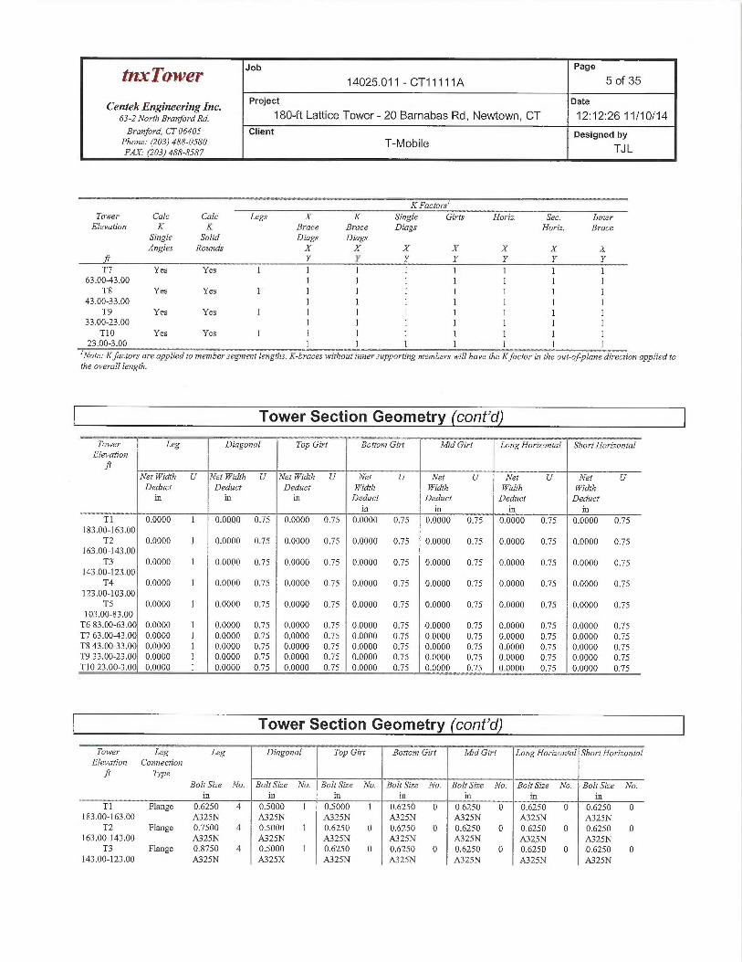
Tower Leg Diagonal Top Girt ~, Bottom Girt Mid Girt Long Hor t~ontal Slaort Hoy izantalElevation
Net Width U Net kVidth U Net YVidth U Net U Net U Net U Net UDeduct Deduct Deduct Width YVidth Width Width
in in in Deduct Deduct Deduct Deductin in in in
Tl 0.0000 1 0.0000 0.75 0.0000 0.75 0.0000 0.75 0.0000 0.75 0.0000 0.75 0.0000 0.75183..00-163.00
T2 0.0000 l 0.0000 0.75 0.0000 0.75 0.0000 0.75 0.0000 0.75 0.0000 0.75 0.0000 0.75163.00-143..00
T3 0.0000 1 0.0000 0.75 0.0000 0.73 0.0000 0.75 0.0000 0.75 0.0000 0.75 0.0000 0.75143.00-123..00
T4 0.0000 1 0.0000 0.75 0.0000 0.75 0.0000 0.75 0.0000 0.75 0.0000 0.75 0.0000 0.75123.00-103.00
TS .0.0000 1 0.0000 0.75 0.0000 0.75. 0,0000 0.75 0.6000 0.75 0.0000 0.75 0.0000 0.75103.00-83.00
T6 83.00-63.00 0.0000 1 0.0000 0.75 0.0000 0.75 0.0000 0.75 0.0000 0.75 0.0000 0.75 0.0000 0.75T7 63.00-43.00 0.0000 1 0.0000 0.75 0.0000 0.75 0.0000 0.75 0:0000 0.75 0.0000 0.75 0.0000 0.75T8 43.0033.0 0.0000 1 0.0000 0.75 0.0000 0.75 0.0000 0.75 0.0000 0.75 0.0000 0.75 0.0000 0.75T9 33.00-23.00 0.0000 1 0.0000 0.75 0.0000 0.75 0.0000 0.75 0.0000 0.75 0.0000 0.75 0.0000 0.75T10 23.00-3.00 0.0000 1 0.0000 0.75 0.0000 0.75 0.0000 0.75 0.0000 0.75 0.0000 0.75 0.0000 0.75
Tower Section Geometry (cont'd)
Towez~ Leg Leg Diago~aal Top Girt Bottom Girt Mid Girt~LongHor~izontal Short HorizontalElevation Connection
ft Type
Bolt Size No. Bolt Size No. Bolt Size No. Bolt Size No. Bolt Size No. Bolf Size No. Bolt Size No.in in in in in in in
T1 Flange 0.6250 4 0.5000 1 0.5000 1 0.6250 0 0.6250 0 p.6250 0 0.6250 0183.00-163.00 A325N A325N A325N A325N A325N A325N A325N
T2 Flange 0.7500 4 0.5000 1 0.6250 0 0.6250 0 0.6250 0 0.6250 0 0.6250 0163.00-143.00 A325N A325N A325N A325N A325N A325N A325N
T3 Flange 0.8750 4 0.5000 1 0.6250 0 0.6250 0 0..5250 0 0.6250 0 D.6250 0143.00-123.00 A325N A325X A325N A325N A325N A325N A325N
Job Page
tnxTower 14025.011 - CT11111A 6 of 35
Centek Engineering Inc. Project Date
63-zNo~-rhB~~a~,fo~~ana. 180-ft Lattice Tower- 20 Barnabas Rd, Newtown, CT 12:12:26 11/10/14Branford, CT 06405 Client Designed by
Phone: (203) 488-0580 T-MobileFAX (203) 488-8587 TJL
.._ V. ~ -:_______ - __ ...__ _ ~ _..____ . __. .Tower Leg Leg Diagonal Toy Giri Bottom Girt tl~id Girt Long Horizontal ShortHorizontad
Elevation Connectdonft Type
Bolt Size No. Bolt Size No. Bolt Size No. Bolt Size No. Bolt Sdze No. Bolt Szze No. Bolt Size No.in in in in in in in
T4 Flange 1.0000 4 0.6250 1 0.6250 0 0.6250 0 0.6250 0 0.6250 0 0.6250 0123.00-103.00 A325N A325N A325N A325N A325N A325N A325N
TS Flange 1.0000 4 0.7500 1 0.6250 0 0.6250 0 0.6250 0 0.6250 0 0.6250 0103.00-83.00 A325N A325N A325N A325N A325N A325N A325NT6 83.00-63.00 Flange 1.0000 4 0.7500 1 0.6250 0 0.6250 0 0.6250 0 0.6250 0 D.6250 0
A325N A325N A325N A325N A325N A325N A325NT7 63.003.00 Flange 1.0000 6 0.7500 1 0.6250 0 0.6250 0 0.6250 0 0.6250 0 0.6250 0
A325N A325X A325N A325N A325N A325N A325NT8 43.0033.00 Flange 0.0000 0 0.7500 1 0.6250 0 0.6250 0 0.6250 0 0.6250 0 0.6250 0
A325N A325X A325N A325N A325N A325N A325NT9 33.00-23.00 Flange 1.0000 6 0.8750 1 0.6250 0 0.6250 0 0.6250 0 0.6250 0 0.6250 0
A325N A325N A325N A325N A325N A325N A325NT10 23.00-3.00 Flange 1.0000 6 0.8750 1 0.6250 0 0.6250 0 0.6250 0 0.6250 0 0.6250 0
A449 A325N A325N A325N A325N A325N A325N
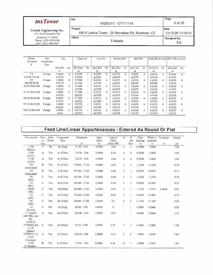
Feed Line/Linear Appurtenances -Entered As Round Or Flat
Description Face Allow Component Placement Face Lateral # # Clear YVidth or Perimeter Weighto~• Shield ape Offset Offset Per Spacing DiameterLeg ft in (Prat FYV) Row in iii in plf
1 5/8 C No Ar (Leg) 91.00 - 3.00 0.0000 -0.02 6 3 0.5000 1.9800 1.04(Sprint)1 5/8 A Yes Ar (CfAe) 135.00 - 3.00 2.0000 0.02 6 6 0.5000 1.9800 1.04(ATT)1 5/8 A Yes Ar (CfAe) 135.00 - 3.00 2.0000 -0.04 3 3 0.5000 1.9800 1.04(ATT)
7/8 B Yes Ar (CfAe) 139.00 - 17.00 2.0000 -0.47 1 1 1.1100 1.1100 0.54(Municipal)
1/2 B Yes Ar (CfAe) 183.00 - 17.00 2.0000 -0.46 1 1 0.5800 0.5800 0.25(Municipal)
7/8 C Yes Ar (CfAe) 183.00 -17.00 2.0000 -0.45 1 1 1.1100 l .11 00 0.54
~)I/2 C Yes Ar (CfAe) 183.00 - 17.00 2.0000 -0.44 1 1 0.5800 0.5800 0.25
~)EW63 C Yes Af (CfAe) 183.00 - 17.00 2.0000 -0.43 1 ] 1.5742 1.5742 5.0668 0.51~~1/2 C Yes Ar (CfAe) 176.00 - 17.00 2.0000 -0.42 1 1 0.5800 0.5800 0.25
~~7/8 C Yes Ar (CfAe) 160.00 - 17.00 2.0000 -0.4 2 2 1.1100 1.1100 0.54
~)1/2 C No Ar (Leg) 62.00 - 3.00 0.0000 0 1 1 0.5800 0.5800 0.25
(Sprint)3"Conduit A Yes Ar (CfAe) 135.00 - 3.00 2.0000 -0.01 1 1 0.0000 3.0000 1.16
with Fiber andDC
(AT&T)HYBRIFLEX C Yes Ar (CfAe) 91.00 - 3.00 2.0000 0.45 3 3 1.5400 1.5400 130
1-1/4"(Sprint)
HYBRIFLEX B Yes Ar (CfAe) 126.00 - 3.00 2.0000 -0.44 2 2 1.9800 1.9800 1.901-5/8"
(Verizon)1 5/8 B Yes Ar (CfAe) 147.00 - 3.00 0.0000 0.41 13 7 1.9800 1.9800 1.04
(T-Mobile -

Job Page
~'~~~r 14025.011 - CT11111A 7 of 35
CentekEngineeringlnc. Project pate
63-zzvo~•eharanfoYaxa. 180-ft Lattice Tower - 20 Barnabas Rd, Newtown, CT 12:12:26 11/10/14Branford, CT 06405 Client Designed by
Phone: (203)488-0580 T-Mobile TJLFAX.- (203) 488-8587
Descriytion Face Allow Comyonent Placement Face Lateral # # Clear Width or Perimeter Weightor Shield Type Offset Offset Per Spacing DiameterLeg ft in (Prat FYI Row in in in plf
Proposed)
Feed Line/Linear Appurtenances Section Areas
Tower ~ Tower Face ~ AR AF ~ CAA CAAA WeightSection Elevation In Face Out Face
Tl 183.00-163.00 A 0.000 0.000 0.000 0.000 0.00B 0.967 0.000 0.000 0.000 0,01C 3.445 2.624 0.000 0.000 0.03.
T2 163.00-143.00 A 0.000 0.000 0.000 0.000 0.00B 5.587 0.000 O.000 O.OdO 0.06C 6.928 2.624 0.000 0.000 0.05
T3 143.00-123.00 A 20.820 0.000 0.000 0.000 0.13B 26.537 0.000 0.000 0.000 0.30C 7.483 2.624 0.000 0.000 0.05
T4 123.00-103.00 A 34.700 0.000 0.000 O.000 0.21B 32.517 0.000 0.000 0.000 036C 7.483 2.624 0.000 0.000 0.05
TS 103.00-83.00 A 38.660 0.000 0.000 0.000 0.21B 32.517 0.000 0.000 0.000 036C 14.523 2.624 0.000 0.000 0.13
T6 83.00-63.00 A 44.600 0.000 0.000 0.000 021B 32.517 0.000 0.000 0.000 036C 25.083 2.624 0.000 0.000 026
T7 63.00-43.00 A 45.518 0.000 0.000 0.000 0.21B 32.517 0.000 0.000 0.000 036C 26.002 2.624 0.000 0.000 026
T8 43.00-33:00 A 22.783 0.000 0.000 0.000 0.11B 16.258 0.000 0.000 0.000 0.18C 13.025 1.312 0.000 0.000 0.13
T9 33.00-23.00 A 22.783 0.000 0.000 0.000 0.11B 16.258 0.000 0.000 0.000 0.18C 13.025 1312 0.000 0.000 0.13
T10 23.00-3.00 A 45.567 0.000 0.000 0.000 0:21B 30.545 0.000 0.000 0.000 035C 20.812 0.787 0.000 0.000 0.22
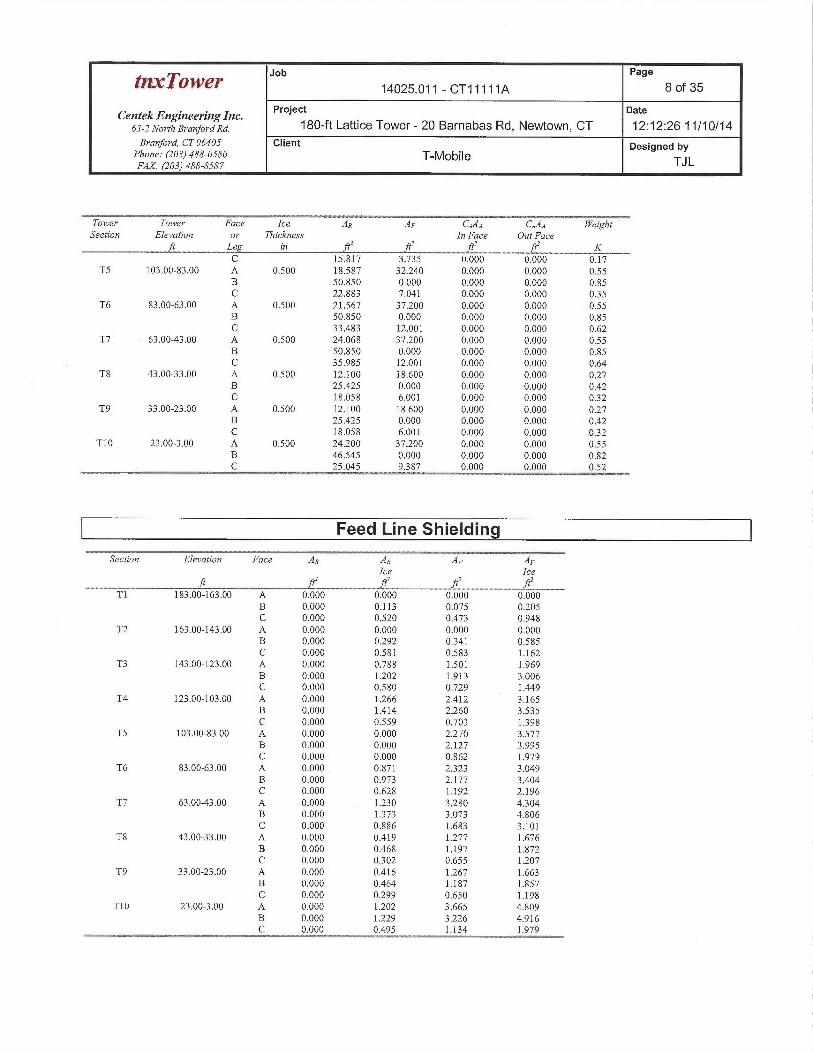
Feed Line/Linear Appurtenances Section Areas -With Ice
Tower Tower Face Ice AR AF CA•4A CAAA WeightSection. Elevation or Thickness In Face Out Face
ft Leg in ftZ ft fiZ ft' KTl 183.00-163.00 A 0.500 0.000 0.000 0.000 0.000 0.00
B 2.633 0.000 0.000 0.000 0.02C 7.862 3.735 0.000 0.000 0.10
T2 163.00-143.00 A 0.500 0.000 0.000 0.000 0.000 0.00B 9.587 0.000 0.000 0.000 0.15C 14.762 3.735 0.000 0.000 0.16
T3 143.00-123.00 A 0.500 9.960 17.360 0.000 0.000 033B 41.703 0.000 0.000. 0.000 0.73C 15.817 3.735 0.000 0.000 0.17
T4 123.00-103.00 A 0.500 16.600 28.933 0.000 0.000 0.55B 50.850 0.000 0.000 0.000 0.85
Job Page
tnxTower 14025.011 - CT11111A 8 of 35
Centek Engineering Inc. Project Date
63-zNo7-rna~~anfo,~ana. 180-ft Lattice Tower- 20 Barnabas Rd, Newtown, CT 12:12:26 11/10/14Branford, CT 06405 Client Designed by
Phone: (203) 488-0580 T-MOblle TJLFAX.• (203) 488-8587
Tower Tower ~ Face Ice ~ ~ AR~ AF ~ C,iAA CAAA WeightSection Elevation or Thickness In Face Out Face
ft Leg in ft' ftZ ft' ftz KC 15.817 3.735 0.000 0.000 0.17
TS 103.00-83.00 A 0.500 18.587 32.240 0.000 0.000 0.55B 50.850 0.000 0.000 0.000 0.85C 22.883 7.041 0.000 0.000 035
T6 83.00-63.00 A 0.500 21.567 37.200 0.000 0.000 0.55B 50.850 0.000 0.000 0.000 0.85C 33.483 12.001 0.000 0.000 0.62
T7 63.00-43.00 A 0.500 24.068 37.200 0.000 0.000 0.55B 50.850 0.000 0.000 0.000 0.85C 35.985 12.001 0.000 0.000 0.64
T8 43.00-33.00 A 0.500 12.100 18.600 0.000 0.000 0.27B 25.425 0.000 0.000 0.000 0.42C 18.058 6.001 0.000 0.000 032
T9 33.00-23.00 A 0.500 12.100 18.600 0.000 0.000 0.27B 25.425 0.000 0.000 0.000 0.42C 18.058 6.001 0.000 0.000 0.32
T10 23.00-3.00 A 0.500 24.200 37.200 0.000 0.000 0.55B 46.545 0.000 0.000 0.000 0.82C 25.045 9.387 0.000 0.000 0.52
Feed Line Shielding
Section Elevation Face AR ~ AR ~ ~ AF AFIce Ice
T1 183.00-163.00 A 0.000 0.000 0.000 0.000B 0.000 0.113 0.075 0.205C 0.000 0.520 0.473 0.948
T2 163.00-143.00 A 0.000 0.000 0.000 0.000B 0.000 0.292 0341 0.585C 0.000 0.581 0.583 1.162
T3 143.00-123.00 A 0.000 0.788 1.501 1.969B 0.000 1.202 1.913 3.006C 0.000 0.580 0.729 1.449
T4 123.00-103.00 A 0.000 1.266 2.412 3.165B 0.000 1.414 2.260 3.535C 0.000 0.559 0.703 1398
TS 103.00-83.00 A 0.000 0.000 2.270 3.577B 0.000 0.000 2.127 3.995C 0.000 0.000 0.862 1.979
T6 83.00-63.00 A 0.000 0.871 2323 3.049B 0.000 0.973 2.177 3.404C 0.000 0.628 1.192 2.196
T7 63.00-43.00 A 0.000 1.230 3.280 4304B 0.000 1.373 3.073 4.806C 0.000 0.886 1.683 3.101
T8 43.00-33.00 A 0.000 0.419 1.277 1.676B 0.000 0.468 1.197 1.872C 0.000 0302 0.655 1.207
T9 33.00-23.00 A 0.000 0.416 1.267 1.663B 0.000 0.464 1.187 1.857C 0.000 0.299 0.650 1.198
T10 23.00-3.00 A 0.000 1.202 3.665 4.809B 0.000 1.229 3.226 4.916C 0.000 0.495 1.134 1.979
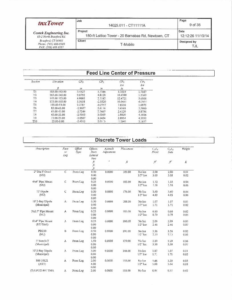
Job Page
~~Q~~r 14025.011 - CT11111A 9 of 35
Centek Engineering Inc. Project Date
63-Z NorthB~~an}oraxa. 180-ft Lattice Tower- 20 Barnabas Rd, Newtown, CT 12:12:26 11/10/14Brantford, CT 06405 Client Designed by
Phone: (203) 488-0580 T-MobileFAX. (203) 488-8587 TJ L
Feed Line Center of Pressure
~Secfion Elevation ~ CPX ~ ~ CPz~ ~ CPX CPzIce Ice
ft in in in inTl 183.00-163:00 3.4327 1.7386 4.1619 1.7337T2 163.00-143.00 9.0792 4.8128 10.4389 5.2360T3 143.00-123.00 8.9895 2.3182 12.4721 3.6866T4 123.00-103.00 5.5618 23520 10.0451 -0.7014TS 103.00-83.00 2.2787 -0.2757 7.8310 1.0875T6 83.00-63.00 -23687 2.6116 3.6388 3.5860T7 53.00-43.00 -2.7249 2.7407 2.4129 3.8736T8 43.00-33.00 -2.9569 3.0369 2.8020 43826T9 33.00-23.00 -3.0507 3.1454 2.8954 4.5352T10 23.00-3.00 -5.4915 2.0513 -1.2941 3.1657
Discrete Tower Loads
Description Face Offset Offsets: Azimuth Placement C,iAg C,~A~ Weightor Type Horz Adjustment Front SideLeg Lateral
Vert
.~ .~ ~~ ~ K
2" Dia 8' Omni C From Leg 0.50 O.000O 189.00 No Ice 2.00 2.60 0.01(NLJ) 0.00 1/2"Ice 3.03 3:03 0.02
0.004Sc4" Pipe Mount C From Leg 0.25 0.0000 183.00 No Ice 1.32 1:32 0.04
(NU) 0.00 1/2"Ice 1.58 1.58 OA60.00
12' Dipole C From Leg 0.50 0.0000 176.00 No Ice 3.60 3.60 0.04(N Cn 0.00 ll2"Ice 4.83 4.83 0.06
0.0010' 2-Bay Dipole A From Leg 0.50 0.0000 188.00 No Ice 1.07 1.07 0.01(Municipal} OAO 1/2"Ice 1.71 1.71 Q.02
0.003'x2.5" Pipe Mount A From Leg 0.25 0.0000 183.00 No Ice 0.60 0.60 0.02
(NL~ 0.00 1/2"Ice 0.79 0.79 O.Q30.00
6'x4" Pipe Mount A From Leg 0.25 0.0000 180.00 No Ice 2.09 2.09 0.05(NiJ Dish) 0.00 1/2"Ice 2.46 2.46 0.07
0.00PD220 B From Leg 0.50 0.0000 191.00 No Ice 3..56 3.56 0.02(N~C~ O.Oq 1/2° Ice 7.13 7.13 OAS
0.003' Standoff A From Leg 1.50 0.0000 139.00 No Ice 2.20 2.20 0.06(Municipal) 0.00 1/2"Ice 330 330 0.07
0.0010' 2-Bay Dipole A From Leg 3.00 D,0000 144.00 No Ice 1.07 1.Q7 0.01(Municipal) 0.00 1/2" Ice 1.71 1.7I O.Q2
0.00800 10121 A From Leg 2.00 0.0000 135.00 No Ice 5.46 3.29 0.05(ATT) 4.00 1/2"Ice 5:88 3.64 0.08
0.00(2) LPG21401 TMA A From Leg 2.00 0.0000 135.00 No Ice 0.95 037 0.02
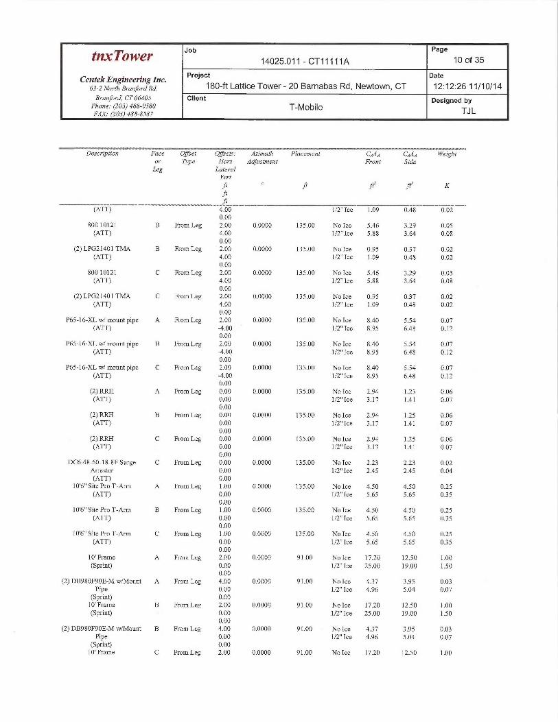
Job Page
tnxTow~r 14025.011 - CT11111A 10 of 35
CentekEngineeringlnc. Project Date
63-2 NorthBranforaRa. 180-ft Lattice Tower - 20 Barnabas Rd, Newtown, CT 12:12:26 11/10/14Branford, CT 06405 Client Designed by
Phone: (203) 488-0580 T-MobileFAX.• (l03) 488-8587 TJ L
Description Face Offset Offsets: Azimuth Placement CA,4A C,~AA Weightor Type Horz Adjustment Front SideLeg Lateral
Yert
.~ ~ .~ .~ K
(ATT) 4.00 1/2"Ice 1.09 0.48 0.020.00
800 10121 B From Leg 2.00 0.0000 135.00 No Ice 5.46 3.29 0.05(ATT) 4.00 1/2"Ice 5.88 3.64 0.08
0.00(2) LPG21401 'I'MA B From Leg 2.00 0.0000 135.00 No Ice 0.95 037 0.02
(ATT) 4.00 1/2"Ice 1.09 0.48 0.020.00
800 10121 C From Leg 2.00 0.0000 135.00 No Ice 5.46 3.29 0.05(ATT) 4.00 1/2"Ice 5.88 3.64 0.08
0.00(2) LPG21401 TMA C From Leg 2.00 0.0000 135.00 No Ice 0.95 037 0.02
(ATT) 4.00 1/2" Ice 1.09 0.48 0.020.00
P65-16-XL w/ mount pipe A From Leg 2.00 0.0000 135.00 No Ice 8.40 5.54 0.07(ATT) -4.00 1/2" Ice 8.95 6.48 0.12
0.00P65-16-XL w/ mount pipe B From Leg 2.00 0.0000 135.00 No Ice 8.40 5.54 0.07
(ATT) -4.00 1/2"Ice 8.95 6.48 0.120.00
P65-16-XL w/ mount pipe C From Leg 2.00 0.0000 135.00 No Ice 8.40 5.54 0.07(ATT) -4.00 1/2"Ice 8.95 6.48 0.12
0.00(2) RRH A From Leg 0.00 0.0000 135.00 No Ice 2.94 1.25 0.06(ATT) 0.00 1/2"Ice 3.17 1.41 0.07
0.00(2) RRH B From Leg 0.00 0.0000 135.00 No Ice 2.94 1.25 0.06(ATT) 0.00 1/2"Ice 3.17 1.41 0.07
0.00(2) RRH C From Leg 0.00 0.0000 135.00 No Ice 2.94 1.25 0.06(ATT) 0.00 1/2"Ice 3.17 1.41 0.07
0.00DC6~8-60-18-8F Surge C From Leg 0.00 0.0000 135.00 No Ice 223 2.23 0.02
Arrestor 0.00 1/2" Ice 2.45 2.45 0.04(ATT) 0.00
10'6" Site Pro T-Arm A From Leg 1.00 0.0000 135.00 No Ice 4.50 4.50 0.25(ATT) 0.00 1/2"Ice 5.65 5.65 035
0.0010'6" Site Pro T-Arm B From Leg 1.00 0.0000 135.00 No Ice 4.50 4.50 0.25
(ATT) 0.00 1/2"Ice 5.65 5.65 0350.00
10'6" Site Pro T-Arm C From Leg 1.00 0.0000 135.00 No Ice 4.50 4.50 0.25(ATT) 0.00 1/2"Ice 5.65 5.65 035
0.0010' Frame A From Leg 2.00 0.0000 91.00 No Ice 17.20 12.50 1.00(Sprint) 0.00 1/2" Ice 25.00 19.00 1.50
0.00(2) DB980F90E-M w/Mount A From Leg 4.00 0.0000 91.00 No Ice 437 3.95 0.03
Pipe 0.00 1/2"Ice 4.96 5.04 0.07(Sprint) 0.0010' Frame B From Leg 2.00 0.0000 91.00 No Ice 17.20 12.50 1.00(Sprint) 0.00 1/2"Ice 25.00 19.00 1.50
0.00(2) DB980F90E-M w/Mount B From Leg 4.00 0.0000 91.00 No Ice 437 3.95 0.03
Pipe 0.00 1/2"Ice 4.96 5.04 0.07(Sprint) 0.0010' Frame C From Leg 2.00 0.0000 91.00 No Ice 17.20 12.50 1.00
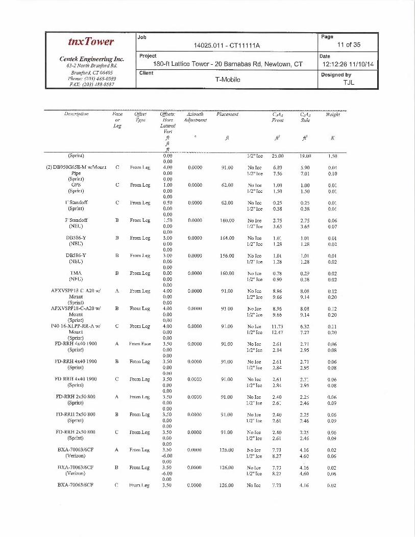
Job Page
tnxTow~r 14025.011 - CT11111A 11 of 35
Centek Engineering Inc. Project Date
63-allorrha,~an}oYana. 180-ft Lattice Tower- 20 Barnabas Rd, Newtown, CT 12:12:26 11/10/14Branford, CT 06405 Client Designed by
Phone: (203)488-0580 T-Mobile TJLFAX.- (203) 488-8587
Description Face Offset Offsets: Azimuth Placement C,~Aq C,~A~ Weightm~ Type Horz Adjustment Front SrdeLeg Lateral
Pertft ft ftZ fl1 K.~
(Sprint) 0.00 1/2"Ice 25.00 19.00 1.500.00
(2) DB950G65E-M w/Mount C From Leg 4.00 0.0000 91.00 No Ice 6.89 5.90 0.04Pipe 0.00 1/2"Ice 7.56 7.01 0.10
(Sprint) 0.00GPS C From Leg 1.00 0.0000 62.00 No Ice 1.00 1.00 0.01
(Sprint) 0.00 1/2"Ice 1.50 1.50 0.01o.00
1' Standoff C From Leg 0.50 0.0000 62.00 No Ice 0.25 0.25 0.01(Sprint) 0.00 1/2" Ice 038 038 0.01
0.003' Standoff B From Leg 1.50 0.0000 160.00 No Ice 2.75 2.75 0.06(NE[J) 0.00 1/2"Ice 3.65 3.65 0.07
0.00DB586-Y B From Leg 3.00 0.0000 164.00 No Ice 1.01 1.01 0.01(NEi~ 0.00 1/2" Ice 1.28 1.28 0.02
0.00DB586-Y B From Leg 3.00 0.0000 156.00 No Ice 1.01 I.Ol 0.01(NEL~ 0.00 1/2"Ice 1.28 1.28 0.02
0.00TMA B From Leg 0.00 0.0000 160.00 No Ice 0.78 0.29 0.02(NEi~ 0.00 1/2"Ice 0.90 038 0.02
0.00APXVSPPI8-C-AZO w/ A From Leg 4.00 0.0000 91.00 No Ice 8.96 8.08 0.12
Mount 0.00 1/2" Ice 9.66 9.14 0.20(Sprint) 0.00
APXVSPPI8-C-A20 w/ B From Leg 4.00 0.0000 91.00 No Ice 8.96 8.08 0.12Mount 0.00 1/2"Ice 9.66 9.14 0.20(Sprint) 0.00
P40-16-XLPP-RR-A w/ C From Leg 4.00 0.0000 91.00 No Ice 11.73 632 0.11Mount 0.00 1/2"Ice 12.47 7.27 0.20(Sprint) 0.00
FD-RRH 4x40 1900 A From Face 3.50 0.0000 91.00 No Ice 2.61 2.71 0.06(Sprint) 0.00 1/2"Ice 2.84 2.95 0.08
0.00FD-RRH 4x40 1900 B From Leg 3.50 0.0000 91.00 No Ice 2.61 2.71 0.06
(Sprint) 0.00 1/2"Ice 2.84 2.95 0.080.00
FD-RRH 4x40 1900 C From Leg 3.50 0.0000 91.00 No Ice 2.61 2.71 0.06(Sprint) 0.00 1/2" Ice 2.84 2.95 0.08
0.00FD-RRH 2x50 800 A From Leg 3.50 0.0000 91.00 No Ice 2.40 2.25 0.06
(Sprint) 0.00 1/2"Ice 2.61 2.46 0.090.00
FD-RRH 2x50 800 B From Leg 3.50 0.0000 91.00 No Ice 2.40 2.25 0.06(Sprint) 0.00 1/2"Ice 2.61 2.46 0.09
0.00FD-RRH 2x50 800 C From Leg 3.50 0.0000 91.00 No Ice 2.40 2.25 0.06
(Sprint) 0.00 1/2"Ice 2.61 2.46 0.090.00
BXA-70063/6CF A From Leg 3.50 0.0000 126.00 No Ice 7.73 4.16 0.02(Verizon) -6.00 1/2"Ice 8.27 4.60 0.06
0.00BXA-70063/6CF B From Leg 3.50 0.0000 126.00 No Ice 7.73 4.16 0.02
(Verizon) -6.00 1/2" Ice 8.27 4.60 0.060.00
BXA-70063/6CF C From Leg 3.50 0.0000 126.00 No Ice 7.73 4.16 0.02
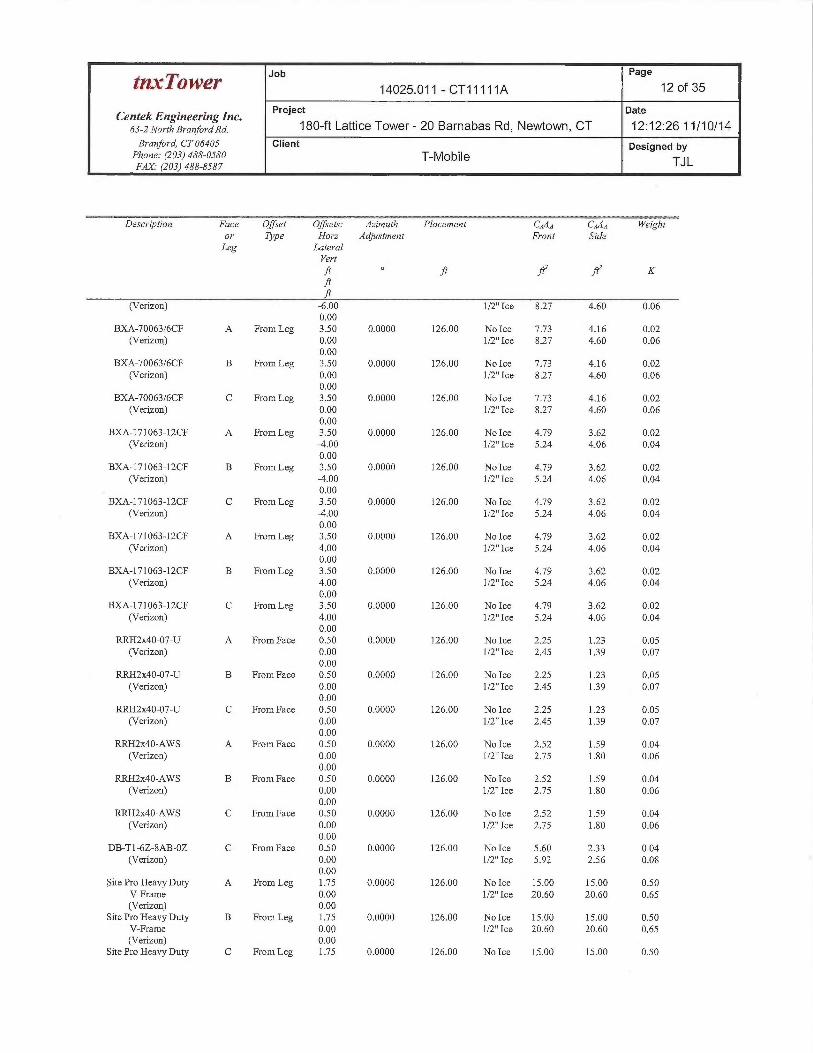
Job Page
~~x~Q~~r 14025.011 - CT11111A 12 of 35
CentekEngineeringlnc. Project gate
63-2NorrhBran}oraRa. 180-ft Lattice Tower - 20 Barnabas Rd, Newtown, CT 12:12:26 11/10/14
Branford, CT 06405 Client Designed byPhone: (203)488-0580 T-MobileFAX.• (203) 488-8587 TJ L
Desc~iptzon Face Offset Offsets: Azimuth Placement C~An C,~AA Weightor Type Horz Adjustment Front SideLeg Lateral
Vert
.h h .~ .~ K
(Verizon) -6.00 1/2"Ice 8.27 4.60 0.060.00
BXA-70063/6CF A From Leg 3.50 0.0000 126.00 No Ice 7.73 4.16 0.02(Verizon) 0.00 1/2"Ice 8.27 4.60 0.06
0.00BXA-70063/6CF B From Leg 3.50 0.0000 126.00 No Ice 7.73 4.16 0.02
(Verizon) 0.00 1/2"Ice 8.27 4.60 0.060.00
BXA-70063/6CF C From Leg 3.50 0.0000 126.00 No Ice 7.73 4.16 0.02(Verizon) 0.00 1/2"Ice 8.27 4.60 0.06
0.00BXA-171063-12CF A From Leg 3.50 0.0000 126.00 No Ice 4.79 3.62 0.02
(Verizon) x.00 1/2"Ice 5.24 4.06 0.040.00
BXA-171063-12CF B From Leg 3.50 0.0000 126.00 No Ice 4.79 3.62 0.02(Verizon) -4.00 1/2"Ice 5.24 4.06 0.04
0.00BXA-171063-12CF C From Leg 3.50 0.0000 126.00 No Ice 4.79 3.62 0.02
(Verizon) -4.00 1/2"Ice 5.24 4.06 0.040.00
BXA-171063-12CF A From Leg 3.50 0.0000 126.00 No Ice 4.79 3.62 0.02(Verizon) 4.00 1/2"Ice 5.24 4.06 0.04
0.00BXA-171063-12CF B From Leg 3.50 0.0000 126.00 No Ice 4.79 3.62 0.02
(Verizon) 4.00 1/2"Ice 5.24 4.06 0.040.00
BXA-171063-12CF C From Leg 3.50 0.0000 126.00 No Ice 4.79 3.62 0.02(Verizon) 4.00 1/2"Ice 5.24 4.06 0.04
0.00RRH2x40-07-U A From Face 0.50 0.0000 126.00 No Ice 2.25 1.23 0.05
(Verizon) 0.00 1/2"Ice 2.45 139 0.070.00
RRH2x40-07-U B From Face 0.50 0.0000 126.00 No Ice 2.25 123 0.05(Verizon) 0.00 1/2" Ice 2.45 139 0.07
0.00RRH~x40-07-U C From Face 0.50 0.0000 126.00 No Ice 2.25 1.23 0.05
(Verizon) 0.00 1/2"Ice 2.45 1.39 0.070.00
RRH2x40-AWS A From Face 0.50 0.0000 126.00 No Ice 2.52 1.59 0.04(Verizon) 0.00 1/2"Ice 2.75 1.80 0.06
0.00RRH2x40-AWS B From Face 0.50 0.0000 126.00 No Ice 2.52 1.59 0.04
(Verizon) 0.00 1/2"Ice 2.75 1.80 0.060.00
RRH~x40-AWS C From Face 0.50 0.0000 126.00 No Ice 2.52 1.59 0.04(Verizon) 0.00 1/2"Ice 2.75 1.80 0.06
0.00DB-T1-6Z-8AB-OZ C From Face 0.50 0.0000 126.00 No Ice 5.60 233 0.04
(Verizon) 0.00 1!2"Ice 5.92 2.56 0.080.00
Site Pro Heavy Duty A From Leg 1.75 0.0000 126.00 No Ice 15.00 15.00 0.50V-Frame 0.00 1/2"Ice 20.60 20.60 0.65(Verizon) 0.00
Site Pro Heavy Duty B From Leg 1.75 0.0000 126.00 No Ice 15.00 15.00 0.50V-Frame 0.00 1/2"Ice 20.60 20.60 0.65(Verizon) 0.00
Site Pro Heavy Duty C From Leg 1.75 0.0000 126.00 No Ice 15.00 15.00 0.50
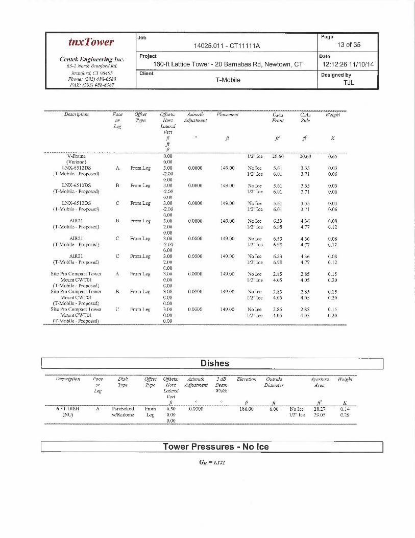
Job Page
~~cxTower 14025.011 - CT11111A 13 of 35
Centek Engineering Inc. Project Date
63-~No~~rhB~~anfo~-axa. 180-ft Lattice Tower- 20 Barnabas Rd, Newtown, CT 12:12:26 11/10/14Branford, CT 06405 Client Designed by
Phone: (203) 488-0580 T-MobileFax ~zo3~ ass-sss~ TJL
Description Face Offset Offsets: Azimuth Placement CA,4A C,3AA Werghtor Type Horz Adjustment Front SideLeg Lateral
Vert
ft ~ J`t ft~ fly Kft
V-Frame 0.00 1/2" Ice 20.60 20.60 0.65(Verizon) 0.00
LNX-6512DS A From Leg 3.00 0.0000 149.00 No Ice 5.61 335 0.03(T-Mobile -Proposed) -2.00 1/2"Ice 6.01 3.71 0.06
0.00LNX-6512DS B From Leg 3.00 0.0000 149.00 No Ice 5.61 3.35 0.03
(T-Mobile -Proposed) -2.00 1/2"Ice 6.01 3.71 0.060.00
LNX-6512DS C From Leg 3.00 0.0000 149.00 No Ice 5.61 335 0.03(T-Mobile -Proposed) -2.00 1/2"Ice 6.01 3.71 0.06
0.00AIR21 B From Leg 3.00 0.0000 149.00 No Ice 6.53 4.36 0.08
(T-Mobile -Proposed) 2.00 1/2" Ice 6.98 4.77 0.120.00
AIR21 C From Leg 3.00 0.0000 149.00 No Ice 6.53 436 0.08(T-Mobile- Proposed) -2.00 1/2"Ice 6.98 4.77 0.12
0.00AIR21 C From Leg 3.00 0.0000 149.00 No Ice 6.53 436 0.08
(T-Mobile -Proposed) 2.00 1/2" Ice 6.98 4.77 0.120.00
Site Pro Compact Tower A From Leg 3.00 0.0000 149.00 No Ice 2.85 2.85 0.15Mount CWT01 0.00 1 /2" Ice 4.05 4.05 0.20
(T-Mobile -Proposed) 0.00Site Pro Compact Tower B From Leg 3.00 0.0000 149.00 No Ice 2.85 2.85 0.15
Mount CWT01 0.00 1/2" Ice 4.05 4.05 0.20(T-Mobile -Proposed) 0.00Site Pro Compact Tower C From Leg 3.00 0.0000 149.00 No Ice 2.85 2.85 0.15
Mount CWTO1 0.00 1/2"Ice 4.05 4.05 0.20(T-Mobile -Proposed) 0.00
Dishes
Descriptio~~ Face Dish Offset Offsets: Azzmuth 3 dB Elevation Outsdde Aperture YPeightor Type Type Hm~z Adjustment Beam Diameter A~~eaLeg Lateral Width
Yertft ~ ~ ft ft ft ~ K
6 FT DISH A Paraboloid From 0.50 0.0000 180.00 6.00 No Ice 28.27 0.14(NU) w/Radome Leg 0.00 1/2"Ice 29.05 0.29
0.00
Tower Pressures - No Ice
Gg = 1121
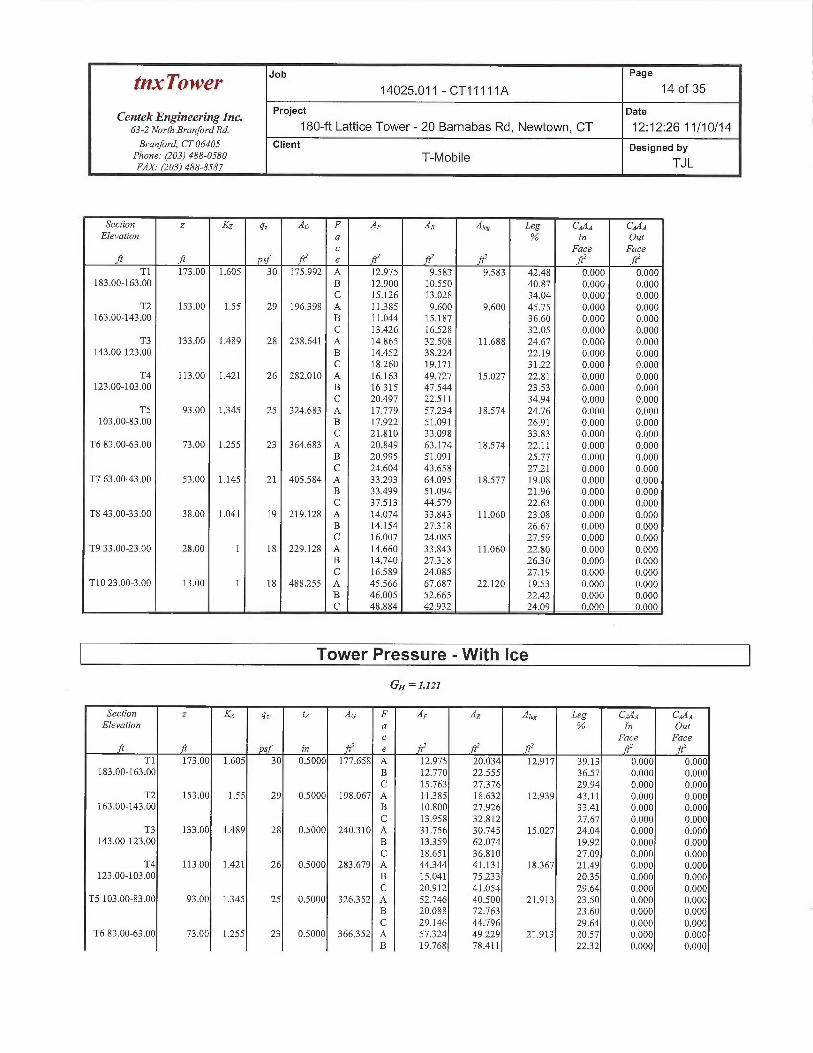
tnxTower Jib Page
14025.011 - CT 11111 A 14 of 35
Centek Engineering Inc. Project Date
63-2NorchBranfo.ana. 180-ft Lattice Tower - 20 Barnabas Rd, Newtown, CT 12:12:26 11/10/14B~~anford, CT 06405 Client Designed by
Phone: (203) 488-0580 T-MobileFAX. (203) 488-8587 TJ L
Section z KZ g, A~ F AF AR A~eg Leg CAAA CA.4AElevation a % In Out
c Face Face.~ .~ Psf ~ e ~Z
Tl 173.00 1.605 30 175.992 A 12.975 9.583 9.583 42.48 0.000 0.000183.00-163.00 B 12.900 10.55 40.87 0.000 0.000
C 15.126 13.028 34.04 0.000 0..000T2 153.00 1.55 29 196398 A 11.385 9.600 9.600 45.75 0.000 0.000
163.00-143.00 B 11.044 15.187 36.60 0.000 0.000C 13.426 16.528 32.05 0.000 0.000
T3 133.00 1.489 28 238.641 A 14.865 32.508 11.688 24.67 0.000 0.000143.00-123.00 B 14.452 38.224 22.19 0.000 0.000
C 1 &.260 19.171 3122 0.000 0.000T4 113.00 1.421 26 282.010 A 16.163 49.727 15.027 22.81 0.000 0.000
123.00-103.00 B 16315 47.544 23.53 0.000 0.000C 20.497 22.511 34.94 0.000 0.000
TS 93.00 1345 25 324.683 A 17.779 57.234 18.574 24.76 0.000 0.000103.00-83.00 B 17.922 51.091 26.91 0.000 0.000
C 21.810 33.098 33.83 0.000 0:000T6 83.00-63.00 73.00 1255 23 364.683 A 20.849 63.174 18.574 22.11 0.000 0.000
B 20.995 51.091 25.77 0.000 0.000C 24.604 43.658 27.21 0.000 0.000
T7 63.00-43.00 53.00 1.145 21 405.584 A 33.293 64.095 18.577 19.08 0.000 0.000B 33.499 51.094 21.96 0.000 0.000C 37.513 44.579 22.63 0.000 0.000
T8 43.00-33.00 38.00 1.041 19 219.128 A 14.074 33.843 11.060 23.08 0.000 0.000B 14.154 27318 26.67 0.000 0.000C 16.007 24.085 27.59 0.000 0.000
T9 33.00-23.00 28.00 1 18 229.128 A 14.660 33.843 11.060 22.80 0.000 0.000B 14.740 27.318 2630 0.000 0.000C 16.589 24.085 27.19 0.000 0.000
T10 23.00-3.00 13.00 1 18 488.255 A 45.566 67.687 22.120 19.53 0.000 0.000B 46.005 52.665 22.42 0.000 0.000C 48.884 42.932 24.09 0.000 0.000
Tower Pressure -With Ice
GH =1.121
Section z KZ q~ tZ A~ F AF AR A~eg Leg C,~AA CA•4~Elevation a % In Out
c Face Facesf in ' e ft' ' ft' - ft'
Tl 173.00 1.605 30 0.5000 177.658 A 12.975 20.034 12.917 39.13 0.000 0.000183.00-163.00 B 12.770 22.555 36.57 0.000 0.000
C 15.753 27376 29.94 0.000 0.000T2 153.00 1.55 29 0.5000 198.067 A 11.385 18.632 12.939 43.11 0.000 0.000
163.00-143.00 B 10.800 27.926 33.41 0.000 0.000C 13.958 32.812 27.67 0.000 0.000
T3 133.00 1.489 28 0.5000 240310 A 31.756 30.745 15.027 24.04 0.000 0.000143.00-123.00 B 13359 62.074 19.92 0.000 0.000
C 18.651 36.810 27.09 0.000 0.000T4 113.00 1.421 26 0.5000 283.679 A 44344 41.131 18367 21.49 0.000 0.000
123.00-103.00 B 15.041 75.233 2035 0.000 0.000C 20.912 41.054 29.64 0.000 0,000
T5103.00-83.00 93.00 1345 25 0.5000 326352 A 52.746 40.500 21.913 23.50 0.000 0.000B 20.088 72,763 23.60 0.000 0.000C 29.146 44.796 29.64 0.000 0.000
T6 83.00-63.00 73.00 1.255 23 0.5000 366352 A 57324 49.229 21.913 20.57 0.000 0.000B 19.768 78.411 22.32 0.000 0.000
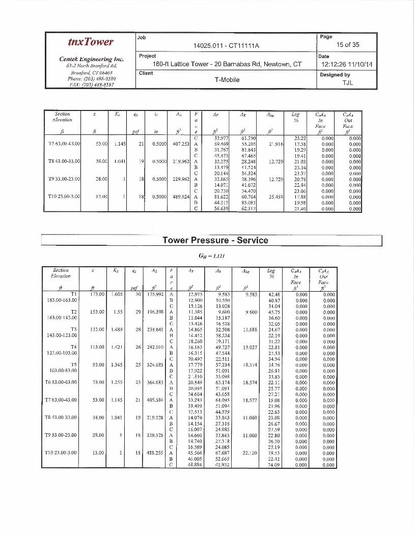
Job Page
~~.~Tower 14025.011 - CT11111A 15 of 35
CentekEngineeringlnc. Project Date
63-2 NorthBranfo~axa. 180-ft Lattice Tower - 20 Barnabas Rd, Newtown, CT 12:12:26 11/10/14Branford, CT 06405 Client Designed by
Phone: (203) 488-0580 T-MobileFAX.• (203) 488-8587 TJ L
Section z KZ y, tZ A~ F AF AR A~eg Leg CAAA CAAAElevation a % In Out
c Face Faceft ft ysf in fC' e fC ~ ftz ft' ftZ
C 32.977 6139Q 23.22 0.000 0.000T7 63.00-43.00 53.00 1.145 21 0.5000 407.253 A 64.469 55.205 21.916 17.58 0.000 0.000
B 31.767 81.843 19.29 0.000 0.000C 45.473 67.465 19.41 0.000 0.000
T8 43.00-33.00 38.00 1.041 19 0.5000 219.962 A 32.275 28.248 12.729 21.03 0.000 0.000B 13,479 41.524 23.14 0.000 0.000C 20.144 34.324 23.37 0.000 0.000
T9 33.00-23.00 28.00 1 18 0.5000 229.962 A 32.865 28.396 12.729 20.78 0.000 0.000B 14.071 41.672 22.84 0.000 0.000C 20.730 34.470 23.06 0.000 0..000
T10 23.00-3.00 13.00 1 18 0.5000 489.924 A 81.622 60.764 25.459 17.88 0.000 0.000B 44.315 83.083 19.98 0.000 0:000C 56.639 62317 21.40 0.000 0.000
Tower Pressure -Service
GH = I.I2I
Section z KZ q~ A~ F AF AR A~eg Leg CAAA CAAAElevation a % In Out
c Face Facef~ ~ Psf .f~' e ~ .f~' f~' R' f~
Tl 173.00 1.605 30 175.992 A 12.975 9.583 9.583 42.48 0.000 0.000183.00-163.00 B 12.900 10.550 40.87 0.000 0.000
C 15.126 13.Q28 34.04 0.000 0.000T2 153.00 1.55 29 196398 A 11385 9.600 9.600 45.75 0.000 0.000
1.63.00-143.00 B 11.044 15.187 36.60 0.000 0,000C 13.426 16.528 32.05 0.000 0.000
T3 133.00 1.489 28 238.641 A 14.865 32.508 11.688 24.67 0.000 0.000143.00-123.00 B 14.452 38.224 22.19 0.000 0.000
C 18.260 19.171 31.22 0.000 0.000T4 113.00 1.421 26 282.010 A 16.163 49.727 15.027 22:81 .0.000 0.000
123.00-103.00 B 16315 47.544 23.53 O.000 0.000C 20.497 22.511 34.94 0.000 0.000
TS 93.00 1.345 25 324.683 A 17.779 57.234 18.574 24:76 0.000 0,000103.04-83.00 B 17.922 51.091 26.91 0.000 0.000
C 21.810 33.098 33.83 0.000 0,000T6 83.00-63.00 73.00 1.255 23 364.683 A 20.849 63.174 18.574 22.11 0.000 0.000
B 20.995 51.091 25.77 0.000 0.000C 24.604 43.658 27.21 0.000 0.000
T7 63.003.00 53.00 1.145 21 405.584 A 33.293 64.095 18.577 19.08 0.000 0.000B 33.499 51.094 21.96 0.000 0.000C 37.513 44.579 22.63 0.000 0.000
T8 43.00-33.00 38.00 1.041 19 219.128 A 14.074 33.843 11.060 23.08 0.000 0.000B 14.154 27.318 26.b7 0.000 0.000C 16.007 24.085 27.59 0.000 0.000
T9 33.00 23.00 28.00 1 18 229.128 A 14.660 33.843 11.060 22:80 0:000 0.000B 14.740 27318 26.30 0.000 0.000C 16.589 24.085 27.19 0.000 0.000
T10 23.00-3.00 13.00 1 18 488.255 A 45.566 67.687 22.120 19.53 0.000 0.000B 46.005 52.665 22.42 0.000 0.000C 48.884 42.932 24.09 0.000 0.000
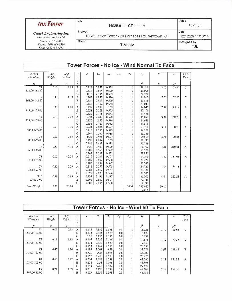
Job Page
~~~~~Y 14025.011 - CT11111A 16 of 35
CentekEngineeringlne. Project pate
63-zNoYrhBranfo~axa. 180-ft Lattice Tower - 20 Barnabas Rd, Newtown, CT 12:12:26 11/10/14Branford, CT 06405 Client Designed by
Phone: (203) 488-0580 T-MobileFAX.• (203) 488-8587 TJL
Tower Forces - No Ice -Wind Normal To Face
Secfron Add Self F e CF RR DF DR AE F w Ctrl.Elevation Weight YYeight a Face
cK K e K 1
T1 0.03 0.93 A 0.128 2.853 0.57$ 1 1 18.518 2.07 103.42 C183.00-163.00 B 0.133 2.834 0.579 1 1 19.009
C 0.16 2.735 0.583 1 1 22.722T2 0.11 1.13 A 0.107 2.937 0.576 1 1 16.913 2.05 102.27 C
163.00-143.00 B 0.134 2.833 0.579 1 1 19.839C 0.153 2.762 0.582 1 1 23.043
T3 0.47 1.20 A 0.199 2.601 0.59 1 1 34.047 2.90 145.14 B143.00-123.00 B 0.221 2.528 0.595 1 1 37.190
C 0.157 2.746 0.583 1 1 29.428T4 0.63 2.27 A 0.234 2.487 0.598 1 1 45.892 3.36 168.20 A
123.00-103.00 B 0.226 2.51 0.596 1 1 44.658C 0.153 2.762 0.582 1 1 33.595
TS 0.71 3.33 A 0.231 2.496 0.597 1 1 51.961 3.61 180.73 A103.00-83.00 B 0.213 2.555 0.593 1 1 48.221
C 0.169 2.702 0:585 T 1 41.159T6 0.83 2.99 A 0,23 2.498 0.597 1 1 58.569 3.80 19024 A
83.00-63.00 B 0.198 2.604 0.59 1 1 51.135C 0.187 2.639 0.588 1 1 50.269
T7 0.83 4.18 A 0.24 2.467 0.599 1 1 71.712 4.20 210.01 A63,00-43.00 B 0.209 2.568 0.592 1 1 b3.756
C 0.202 2.588 0.591 1 1 63.855T8 0.42 2.24 A 0.219 2.535 0.594 1 1 34.190 1.87 187.06 A
43.00-33.00 B 0.189 2.632 0.588 1 1 30.224C 0.183 2.654 0.587 1 1 30.147
T9 0.42 2.29 A 0.212 2.557 0.593 1 1 34.725 1.84 184.11 A33.00-23.00 B 0.184 2.652 0.587 1 1 30.781
C O.I78 2.673 0.586 1 1 30.705T10 0.79 5.69 A 0.232 2.493 0,547 1 1 86.005 4.44 222.23 A
23.00-3.00 B 0.202 2.:589 0.591 1 1 77.121C 0.188 2.636 0.588 1 1 74.130
Sum Weight: 5.23 26.24 OTM 2363.46 30.16ki -ft
Tower Forces - No Ice -Wind 60 To Face
Secfion Add Self F e CF RR DF DR AE F w Ctrl.Elevation Weight YYeight a Face
cft K K e ftZ K plf
T1 0.03 0.93 A 0.128 2.853 0.578 0.8 1 15.923 1.79 89.65 C183..00-163.00 B 0.133 2.834 0.579 0.8 1 16.429
C 0.16 2.735 0.583 Q.8 1 19.697T2 0.11 1.13 A 0.107 2.937 0.576 0.8 1 14.636 1.81 9035 C
163.00-143.00 B 0.134 2.833 0.579 0.8 1 17.630C 0.153 2.762 0.582 0.8 1 20.358
T3 0.47 120 A 0.199 2.601 0.59 0.8 1 31.074 2.68 133.86 B143.00-123.00 B 0.221 2.528 0.595 0.8 1 34.300
C 0.157 2.746 0.583 0:8 1 25.776T4 0.63 2.27 A 0.234 2.487 0.598 0.8 1 42.660 3.13 15635 A
123.00-103.00 B 0.226 2.51 0.596 0:8 1 41395C 0.153 2.762 0.582 0.8 1 29.495
TS 0.71 3.33 A 0.231 2.496 0.597 0:8 1 48.405 337 16836 A103.00-83.00 B 0.213 2.555 0.593 0.8 1 44.637
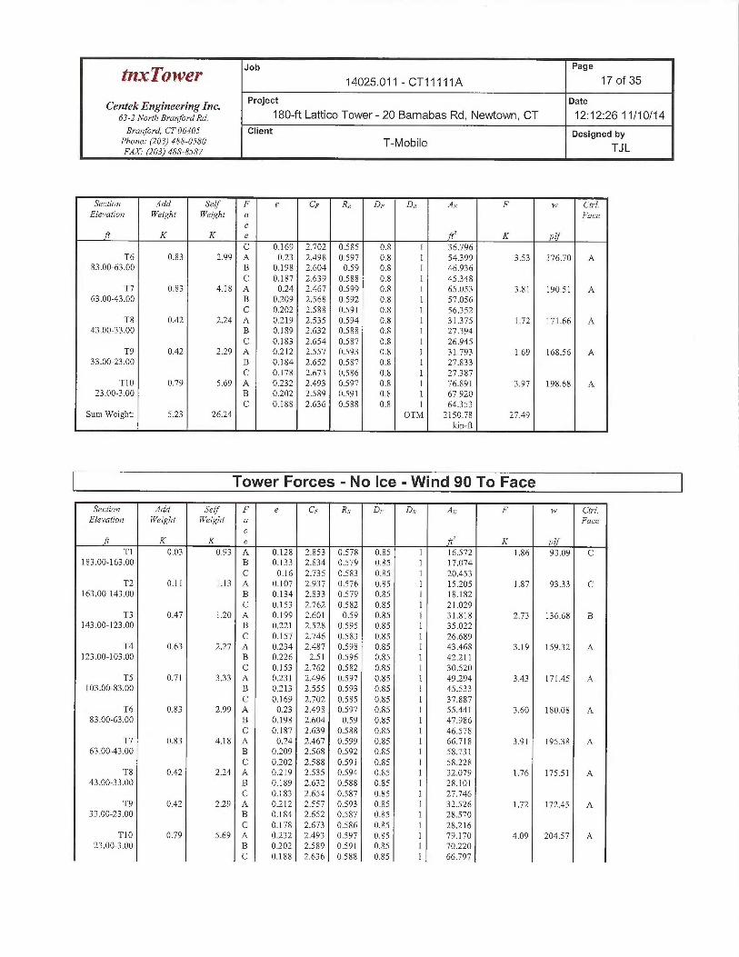
tn.~ ~Q~~~ Job Page
14025.011 - CT 11111 A 17 of 35
Centek Engineering Inc. Project Date
63-z No,-ct,BYa„for~axa. 180-ft Lattice Tower - 20 Barnabas Rd, Newtown, CT 12:12:26 11/10/14Branford, CT 06405 Client Designed by
Pho~ze: (203) 488-0580 T-MobileFAX (203) 488-8587 TJ L
Section Add Self F e CF RR DF DR AE F w Ch~1.Elevatzo~7 Weight Weight a Face
cft K K e fC K plf
C 0.169 2.702 0.585 0.8 1 36.796T6 0.83 2.99 A 0.23 2.498 0.597 0.8 1 54399 3.53 176.70 A
83.00-63.00 B 0.198 2.604 0.59 0.8 1 46.936C 0.187 2.639 0.588 0.8 1 45348
T7 0.83 4.18 A 0.24 2.467 0.599 0.8 1 65.053 3.81 190.51 A63.00-43.00 B 0.209 2.568 0.592 0.8 1 57.056
C 0.202 2.588 0.591 0.8 1 56352T8 0.42 2.24 A 0.219 2.535 0.594 0.8 1 31.375 1.72 171.66 A
43.00-33.00 B 0.189 2.632 0.588 0.8 1 27.394C 0.183 2.654 0.587 0.8 1 26.945
T9 0.42 2.29 A 0.212 2.557 0.593 0.8 1 31.793 1.69 168.56 A33.00-23.00 B 0.184 2.652 0.587 0.8 1 27.833
C 0.178 2.673 0.586 0.8 1 27387T10 0.79 5.69 A 0.232 2.493 0.597 0.8 1 76.891 3.97 198.68 A
23.00-3.00 B 0.202 2.589 0.591 0.8 1 67.920C 0.188 2.636 0.588 0.8 1 64353
Sum Weight: 5.23 26.24 OTM 2150.78 27.49kip-ft
Tower Forces - No Ice -Wind 90 To Face
Section Add Self F e CF RR DF DR AE F w Ch-l.Elevation Weight Weight a Face
cft K K e ft' K if
TI 0.03 0.93 A 0.128 2.853 0.578 0.85 1 16.572 1.86 93.09 C183.00-163.00 B 0.133 2.834 0.579 0.85 1 17.074
C 0.16 2.735 0.583 0.85 1 20.453T2 0.11 1.13 A 0.107 2.937 0.576 0.85 1 15.205 1.87 93.33 C
163.00-143.00 B 0.134 2.833 0.579 0.85 1 18.182C 0.153 2.762 0.582 0.85 ] 21.029
T3 0.47 1.20 A 0.199 2.601 0.59 0.85 1 31.818 2.73 136.68 B143.00-123.00 B 0.221 2.528 0.595 0.85 1 35.022
C 0.157 2.746 0.583 0.85 1 26.689T4 0.63 2.27 A 0.234 2.487 0.598 0.85 1 43.468 3.19 159.32 A
123.00-103.00 B 0.226 2.51 0.596 0.85 1 42.211C 0.153 2.762 0.582 0.85 1 30.520
TS 0.71 333 A 0.231 2.496 0.597 0.85 1 49.294 3.43 171.45 A103.00-83.00 B 0.213 2.555 0.593 0.85 1 45.533
C 0.169 2.702 0.585 0.85 1 37.887T6 0.83 2.99 A 0.23 2.498 0.597 0.85 1 55.441 3.60 180.08 A
83.00-63.00 B 0.198 2.604 0.59 0.85 1 47.986C 0.187 2.639 0.588 0.85 1 46.578
T7 0.83 4.18 A 0.24 2.467 0.599 0.85 1 66.718 3.91 19538 A63.00-43.00 B 0.209 2.568 0.592 0.85 1 58.731
C 0.202 2.588 0.591 0.85 1 58.228T8 0.42 2.24 A 0.219 2.535 0.594 0.85 1 32.079 1.76 175.51 A
43.00-33.00 B 0.189 2.632 0.588 0.85 1 28.101C 0.183 2.654 0.587 0.85 1 27.746
T9 0.42 2.29 A 0.212 2.557 0.593 0.85 1 32.526 1.72 172.45 A33.00-23.00 B 0.184 2.652 0.587 0.85 1 28.570
C 0.178 2.673 0.586 0.85 1 28.216T10 0.79 5.69 A 0.232 2.493 0.597 0.85 1 79.170 4.09 204.57 A
23.00-3.00 B 0.202 2.589 0.591 0.85 1 70.220C 0.188 2.636 0.588 0.85 1 66.797

Job Page
t~.xTOWeP 14025.011 - CT11111A 18 of 35
Centek Engineering Inc. Project Date
63-zNorcha~-anfo~-axa. 180-ft Lattice Tower- 20 Barnabas Rd, Newtown, CT 12:12:26 11/10/14Brm~ford, CT 06405 Client Designed by
Phone: (203) 488-0580 T-Mobile TJLFAX. (203) 488-8587
Section Add Self F e CF RR DF DR AE F w Ctrl.&elevation Weight Weight a Face
cft K K e ftz K plf
Sum Weight: 5.23 26.24 OTM 2203.95 28.16kip-ft
Tower Forces -With Ice -Wind Normal To Face
Section Add Self F e CF RR DF DR AE F w Ch-l.Elevation Wedght YPeight a Face
cft K K e ft~ K ylf
Tl 0.12 1.53 A 0.186 2.644 0.588 1 1 24.747 2.63 131.74 C183.00-163.00 B 0.199 2.6 0.59 1 1 26.081
C 0.243 2.459 0.6 1 1 32.190T2 0.31 1.66 A 0.152 2.766 0.582 1 1 22.223 2.68 133.85 C
163.00-143.00 B 0.196 2.611 0.589 1 1 27.262C 0.236 2.48 0.598 1 1 33.594
T3 1.22 1.91 A 0.26 2.408 0.604 1 1 50342 3.74 187.10 A143.00-123.00 B 0314 2.26 0.62 1 1 51.861
C 0.231 2.496 0.597 1 1 40.632T4 1.56 3.09 A 0301 2.293 0.616 1 1 69.692 4.71 235.42 A
123.00-103.00 B 0318 2.249 0.622 1 1 61.809C 0.218 2.536 0.594 1 1 45313
TS 1.75 4.33 A 0.286 2335 0.612 1 1 77.517 5.04 252.23 A103.00-83.00 B 0.285 2338 0.611 1 1 64.567
C 0.227 2.51 0.596 1 1 55.853T6 2.02 3.97 A 0.291 2.321 0.613 1 1 87.508 5.28 264.10 A
83.00-63.00 B 0.268 2.385 0.607 1 1 67334C 0.258 2.415 0.604 1 1 70.047
T7 2.04 5.60 A 0306 2.28 0.618 1 1 103.574 5.60 280.25 A63.00-43.00 B 0.279 2353 0.61 1 1 81.665
C 0.277 2358 0.609 1 I 86.574T8 1.02 2.86 A 0.275 2.364 0.609 1 1 49.467 2.52 252.43 A
43.00-33.00 B 0.25 2.437 0.602 1 1 38.472C 0.248 2.445 0.601 1 1 40.782
T9 1.02 2.93 A 0.266 2.389 0.606 1 1 50.078 2.48 248.05 A33.00-23.00 B 0.242 2.46 0.6 1 1 39.073
C 0.24 2.468 0.599 1 1 41.391T10 1.89 7.53 A 0.291 2.321 0.613 1 1 118.875 5.72 286.03 A
23.00-3.00 B 0.26 2.408 0.604 1 1 94.537C 0.243 2.459 0.6 1 1 94.034
Sum Weight: 12.93 35.41 OTM 316537 40.42kip-ft
Tower Forces -With Ice -Wind 60 To Face
Section Add Self F e CF RR DF DR AE F w Ctrl.Elevation Weight Weight a Face
cft K K e ft' K plf
T1 0.12 1.53 A 0.186 2.644 0.588 0.8 1 22.152 2.38 118.83 C183.00-163.00 B 0.199 2.6 0.59 0.8 1 23.527
C 0.243 2.459 0.6 0.8 1 29.037
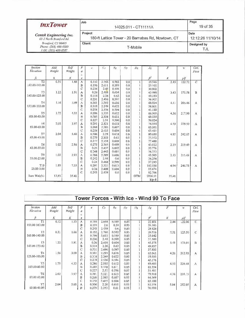
Job Page
tI~OW~r 14025.011 - CT11111A 19 of 35
Centek Engineering Inc. Project gate
63-2 NorthBranforaRa. 180-ft Lattice Tower- 20 Barnabas Rd, Newtown, CT 12:12:26 11/10/14Branford, CT 06405 Client Designed by
Phone: (103)488-0580 T-Mobile TJLFAX.• (203) 488-8587
Section Add Sedf F e C~ RR DF DR AE F w Ctrl.Elevation Weight Weight a Face
cK K e ft' K plf
T2 031 1.66 A 0.152 2.766 0.582 0.8 1 19.946 2.45 122.72 C163.00-143.00 B 0.196 2.611 0.589 0.8 1 25.102
C 0.236 2.48 0.598 0.8 1 30.802T3 1.22 1.91 A 0.26 2.408 0.604 0.8 1 43.990 3.43 171.58 B
143.00-123.00 B 0314 2.26 0.62 0.8 1 49.189C 0.231 2.496 0.597 0.8 1 36.902
T4 1.56 3.09 A 0301 2.293 0.616 0.8 1 60.824 4.11 205.46 A123.00-103.00 B 0318 2.249 0.622 0.8 1 58.801
C 0.218 2.536 0.594 0.8 1 41.130TS 1.75 433 A 0.286 2335 0.612 0.8 1 66.968 436 217.90 A
103.00-83.00 B 0.285 2338 0.611 0.8 1 60.550C 0.227 2.51 0.596 0.8 1 50.024
T6 2.02 3.97 A 0291 2321 0.613 0.8 1 76.044 4.59 229.50 A83.00-63.00 B 0268 2385 0.607 0.8 1 63381
C 0.258 2.415 0.604 0.8 1 63.451T7 2.04 5.60 A 0306 2.28 0.618 0.8 1 89.680 4.85 242.65 A
63.003.00 B 0279 2353 0.61 0.8 1 75312C 0.277 2358 0.609 0.8 1 77.480
T8 1.02 2.86 A 0275 2364 0.609 0.8 I 43.012 2.19 219.49 A43.00-33.00 B 0.25 2.437 0.602 0.8 1 35.776
C 0.248 2.445 0.601 0.8 1 36.753T9 1.02 2.93 A 0.266 2389 0.606 0.8 1 43.505 2.15 215.49 A
33.00-23.00 B 0.242 2.46 0.6 0.8 1 36.258C 024 2.468 0.599 0.8 1 37.245
T10 1.89 7.53 A 0291 2321 0.613 0.8 1 102.550 4.94 246.75 A23.003.00 B 0.26 2.408 0.604 0.8 1 85.674
C 0.243 2.459 0.6 0.8 1 82.706Sum Weight: 12.93 35.41 OTM 2806.55 3~.~6
kip-ft
Tower Forces -With Ice -Wind 90 To Face
Section Add Self F e CF RR DF DR AF F w Ctrl.Elevation Weight Weight a Face
cft K K e ftZ K plf
Tl 0.12 1.53 A 0.186 2.644 0.588 0.85 1 22.801 2.44 122.06 C183.00-163.00 B 0.199 2.6 0.59 0.85 1 24.165
C 0.243 2.459 0.6 0.85 1 29.826T2 031 1.66 A 0.152 2.766 0.582 0.85 l 20.516 2.51 125.50 C
163.00-143.00 B 0.196 2.611 0.589 0.85 1 25.642C 0236 2.48 0.598 0.85 ] 31.500
T3 122 1.91 A 0.26 2.408 0.604 0.85 1 45.578 3.48 173.91 B143.00-123.00 B 0314 2.26 0.62 0.85 I 49.857
C 0.231 2.496 0.597 0.85 I 37.835T4 1.56 3.09 A 0301 2.293 0.616 0.85 1 63.041 4.26 212.95 A
123.00-103.00 B 0.318 2.249 0.622 0.85 1 59.553C 0218 2.536 0.594 0.85 1 42.176
TS 1.75 433 A 0.286 2.335 0.612 0.85 I 69.605 4.53 226.48 A103.00-83.00 B 0.285 2338 0.611 0.85 1 61.554
C 0.227 2.51 0.596 0.85 1 51.481T6 2.02 3.97 A 0.291 2321 0.613 0.85 1 78.910 4.76 238.15 A
83.00-63.00 B 0268 2.385 0.607 0.85 I 64369C 0258 2.415 0.604 0.85 1 65.100
T7 2.04 5.60 A 0306 2.28 0.618 0.85 1 93.154 5.04 252.05 A63.00-43.00 B 0279 2353 0.61 0.85 1 76.900
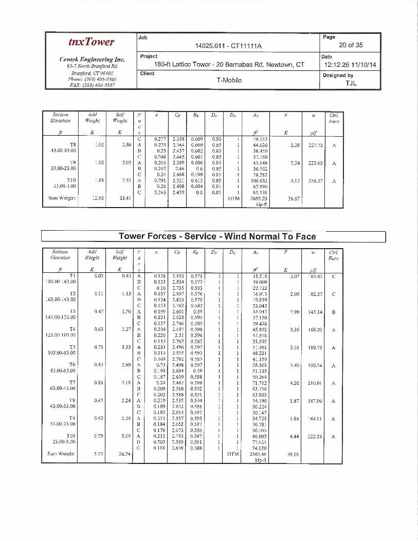
Job Page
tnxTower 14025.011 - CT11111A 20 of 35
Centek Engineering Inc. Project Date
63-zNo~-rhB~~anfo~~ana. 180-ft Lattice Tower- 20 Barnabas Rd, Newtown, CT 12:12:26 11/10/14B~~a~aford, CT 06405 Client Designed by
Pho~se: (203) 488-0580 T-Mobile TJLFAX. (203) 488-8587
Section Add Self F e CF Rn DF DR Ae F w Ctrl.Elevation Weight Weight a Face
cft K K e ft' K plf
C 0.277 2.358 0.609 0.85 1 79.753T8 1.02 2.86 A 0.275 2.364 0.609 0.85 1 44.626 2.28 227.72 A
43.00-33.00 B 0.25 2.437 0.602 0.85 1 36.450C 0.248 2.445 0.601 0.85 1 37.760
T9 1.02 2.93 A 0.266 2389 0.606 0.85 1 45.148 2.24 223.63 A33.00-23.00 B 0.242 2.46 0.6 0.85 1 36.962
C 0.24 2.468 0.599 0.85 1 38.282T10 1.89 7.53 A 0.291 2.321 0.613 0.85 1 106.632 5.13 256.57 A
23.00-3.00 B 0.26 2.408 0.604 0.85 1 87.890C 0.243 2.459 0.6 0.85 1 85.538
Sum Weight: 12.93 35.41 OTM 2892.23 36.67kip-ft
Tower Forces -Service -Wind Normal To Face
Section Add Self F e CF RR DF DR AE F w Ctrl.Elevation Weighi Weight a Face
cft K K e ft~ K if
T1 0.03 0.93 A 0.128 2.853 0.578 1 1 18.518 2.07 103.42 C183.00-163.00 B 0.133 2.834 0.579 1 1 19.009
C 0.16 2.735 0.583 1 1 22.722T2 0.11 1.13 A 0.107 2.937 0.576 1 1 16.913 2.05 102.27 C
163.00-143.00 B 0.134 2.833 0.579 1 1 19.839C 0.153 2.762 0.582 1 1 23.043
T3 0.47 1.20 A 0.199 2.601 0.59 1 1 34.047 2.90 145.14 B143.00-123.00 B 0.221 2.528 0.595 1 1 37.190
C 0.157 2.746 0.583 1 1 29.428T4 0.63 2.27 A 0.234 2.487 0.598 1 1 45.892 336 168.20 A
123.00-103.00 B 0.226 2.51 0.596 1 1 44.658C 0.153 2.762 0.582 1 1 33.595
TS 0.71 333 A 0.231 2.496 0.597 1 1 51.961 3.61 180.73 A103.00-83.00 B 0.213 2.555 0.593 1 1 48.221
C 0.169 2.702 0.585 1 1 41.159T6 0.83 2.99 A 0.23 2.498 0.597 1 1 58.569 3.80 190.24 A
83.00-63.00 B 0.198 2.604 0.59 1 1 51.135C 0.187 2.639 0.588 1 1 50.269
T7 0.83 4.18 A 0.24 2.467 0.599 1 1 71.712 4.20 210.01 A63.00-43.00 B 0.209 2.568 0.592 1 1 63.756
C 0.202 2.588 0.591 1 1 63.855T8 0.42 2.24 A 0.219 2.535 0.594 1 1 34.190 1.87 187.06 A
43.00-33.00 B 0.189 2.632 0.588 1 1 30.224C 0.183 2.654 0.587 1 1 30.147
T9 0.42 2.29 A 0.212 2.557 0.593 1 1 34.725 1.84 184.11 A33.00-23.00 B 0.184 2.652 0.587 1 1 30.781
C 0.178 2.673 0.586 1 1 30.705T10 0.79 5.69 A 0.232 2.493 0.597 1 1 86.005 4.44 222.23 A
23.00-3.00 B 0.202 2.589 0.591 1 1 77.121C 0.188 2.636 0.588 1 1 74.130
Sum Weight: 5.23 26.24 OTM 2363.46 30.16kip-ft
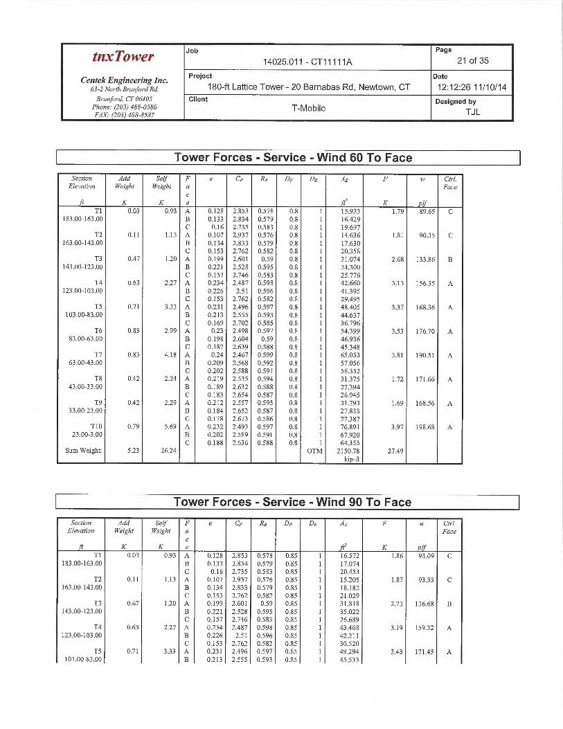
Job Page
tnxTower 14025.011 - CT11111A 21 of 35
CentekEngineeringlnc. Project Date
63-2 NorthBranfo~~ana. 180-ft Lattice Tower - 20 Barnabas Rd, Newtown, CT 12:12:26 11/10/14Branford, CT 06405 Client Designed by
Phone: (203) 488-0580 T-MobileFAX.• (203) 488-8587 TJ L
Tower Forces -Service -Wind 60 To Face
Section Add Self F e CF RR DF DR AE F w Ctrl.Elevation Weight Weight a Face
cK K e K If
T1 0.03 0.93 A 0.128 2.853 0.578 0.8 1 15.923 1.79 89.65 C183.00-153._00 B 0.133 2.834 0.579 0.8 1 16.429
C 0.16 2.735 0.583 0.8 1 19.697T2 0.11 1.13 A 0.107 2.937 0:576 0.8 1 14.636 1.81 9035 C
163.Q0-143.00 B 0.134 2,833 0,579 0.8 1 17.630C 0.153 2.762 0:582 0.8 1 20.358
T3 0.47 1.20 A 0.199 2.601 0,59 0.8 1 31.074 2.68 133.86 B143.00-123.00 B 0.221 2.528 0.595 0.8 1 34300
C 0.157 2.746 0.583 0.8 1 25.776T4 0.63 2.27 A 0.234 2.487 0.598 0.8 1 42.660 3.13 156.35 A
123.00-103.00 B 0.226 2.51 0.596 0.8 1 41395C 0.153 2.762 0.582 0.8 1 29.495
TS 0.71 333 A 0.231 2.496 0.597 0.8 1 48.405 337 168.36 A103:00-83.00 B 0.213 2.555 0.593 0.8 1 44.637
C 0.169 2.702 0.585 0.8 1 36.796T6 0.83 2.99 A 0.23 2.498 0.597 0.8 1 54399 3.53 176.70 A
83.00-63.00 B 0.198 2.604 0.59 0.8 1 46.936C 0.187 2.639 0.588 0.8 1 45.348
T7 0.83 4.18 A 0.24 2.467 0.599 0.8 1 65.053 3.81 190.51 A63.00-43.00 B 0.209 2.568 0.592 0:8 1 57.056
C 0.202 2.588 0.541 0.8 1 56352T8 0.42 2.24 A 0.219 2.535 0.594 0.8 1 31375 1.72 171.66 A
43,00-33.00 B 0.189 2.632 0.588 0.8 1 27394C 0.183 2.654 0.587 0.8 1 26.945
T9 0.42 2.29 A 0.212 2.557 0.593 0~8 1 31..793 1.69 168.56 A33.00-23.00 B 0.184 2.652 0.587 0.8 1 27.833
C 0.178 2.673 0.586 0.8 1 27387T10 0.79 5.69 A 0.232 2.493 0,597 0.8 1 76.891 3.97 198.68 A
23.00-3.00 B 0.202 2.589 0.591 0.8 1 67.920C 0.188 2.636 0.588 0.8 1 64353
Sum Weight: 523 26.24 OTM 2150.78 27.49kip-ft
Tower Forces -Service -Wind 90 To Face
Section Add Self F e CF RR DF DR AE F w Ctrl.Elevation Weight Weight a Face
cft K K e ftZ K if
T1 0.03 0.93 A 0.128 2.853 0.578 0.85 1 16.572 1.86 93.09 C183.00-163.00 B 0.133 2.834 0.579 0.85 1 17.074
C 0.16 2.735 0.583 0.85 1 20.453T2 0.11 1.13 A 0.107 2.937 0.576 0.85 1 15.205 1.87 93.33 C
163.00-143..00 B 0.134 2.833 0.579 0.85 1 18.182C 0.153 2.762 0.582 0.85 1 21.029
T3 0.47 1.20 A 0.199 2.601 0.59 0.85 1 31.818 2.73 136.68 B143.00-123.00 B 0.221 2.528 0.595 0.85 1 35.022
C 0.157 2.746 0.583 0.85 1 26.689T4 0.63 2.27 A 0.234 2.487 0.598 0.85 1 43.468 3.19 15932 A
123.00-103.00 B 0.226 2.51 0.596 0.85 1 42.211C 0.153 2.762 0,582 0.85 1 30.520
TS 0.71 333 A 0.231 2.496 0.597 0.85 1 49.294 3.43 171.45 A103.00-83.00 B 0.213 2.555 0.593 0:85 1 45.533
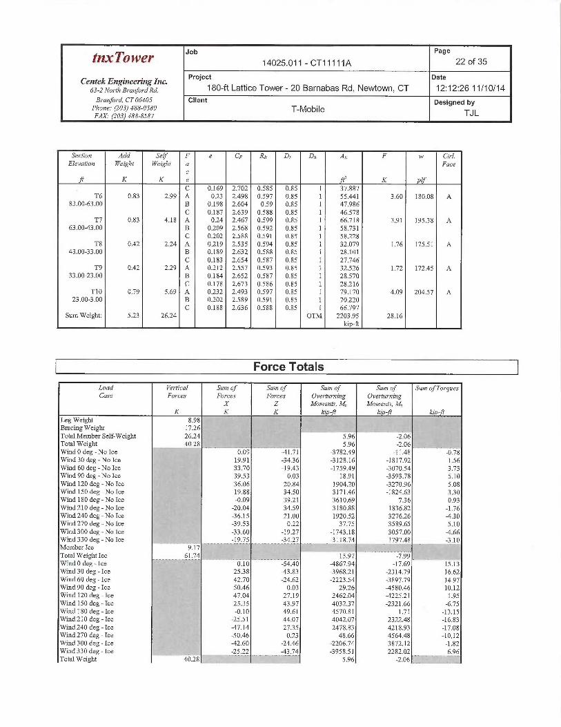
tnxTower J°b Page
14025.011 - CT11111A 22 of 35
CentekEngineeringlnc. Project Date
63-2Norrharanforana. 180-ft Lattice Tower - 20 Barnabas Rd, Newtown, CT 12:12:26 11/10/14Branford, CT 06405 Client Designed by
Phone: (203) 488-O.i80 T-MobileFax. ~zoa)48s-sss~ TJL
Section Add Self F e CF RR DF DR AE F w Ctrl.Elevation YVeight Weight a Face
cft K K e fC' K plf
C 0.169 2.702 0.585 0.85 1 37:887T6 0.83 2.99 A 0.23 2:498. 0.597 0.85 1 55.441 3.60 180.08 A
83.00-63.00 B 0.198 2.604 0.59 0.85 1 47.986C 0.187 2.639 0.588 0.85 1 46.578
T7 0.$3 4.18 A 0.24 2.467 0.599 0.85 1 66.718 3.91 195.38 A63.00-43.00 B 0.209 2.568 0.592 0.85 1 58.731
C 0.202 2.588 0.591 0.85 1 58.228T8 0.42 2.24 A 0.219 2.535 0.594 0.85 1 32.079 1.76 175.51 A
43..00-33.00 B 0.189 2.632 0.588 0.85 1 28.101C 0.183 2.654 0.587 0,85 1 27.746
T9 0.42 2.29 A 0.212 2.557 0.593 0.85 1 32.526 1.72 172.45 A33.00-23.00 B 0.184 2.652 0.587 0.85 1 28.570
C 0.178 2.673 0.586 0.85 1 28.216T10 0.79 5.69 A 0.232 2.493 0.597 0.85 1 79.170 4.09 204.57 A
23.00-3.00 B 0.202 2.589 0.591 0.85 1 70.220C 0.188 2.636 0.58& 0.85 1 66.797
Sum Weight: 5..23 2624 OTM 2203.95 28.16kip-8
Force Totals
Load Vertical Sum of Sum of Sum of Sum of Sum of TorquesCase Forces Forces Forces Overturning Overturning
X Z Moments, M Moments, M,K K K ki -ft Ici -ft ki -
Leg Weight 8.98Bracing Weight 17.26Total Member Self-Weight 26.24 5.96 -2.06Total Weight 40.28 5.96 -2.06
- -- - - - -~Wind 0 deg -No Ice 0.09 -41.71 -3782.49 -11.48 -0.78Wind 30 deg - No Ice 19.91 -34.36 -3128.16 -1817.92 1.56Wind 60 deg -No Ice 33.70 -19.43 -1759.49 3070.54 3.73Wind 90 deg - No Ice 39.53 0.03 18.91 -3593.78 5.10Wind 120 deg - No Ice 36.06 20.84 1904.20 -3270.96 5.08Wind 150 deg - No Ice 19.88 34.50 3171.46 -1824.63 330Wind 180 deg - No Ice -0.09 39.21 3610.69 736 0.93Wind 210 deg - No Ice -20.04 34.59 3180.88 1836.82 -1.76Wind 240 deg-No Ice -36.15 21.00 1920.52 3276.26 -430Wind 270 deg - No Ice -39.53 0.22 37.75 3589:65 -5.10Wind 300 deg - No Ice -33.60 -19.27 -1743.18 3057.00 -4.66Wind330 deg -No Ice -19.75 -34.27 -3118.74 1797.48 -3.10Member Ice 9.17 ____Total Weight Ice 61.74 15.97 -7.99 ...Wind 0 deg -Ice 0.10 -54.40 -4867.94 -17.69 15.13Wind 30 deg -Ice 2538 -43.83 -3968.21 -2314.79 16.62Wind 60 deg -Ice 42.70 -24.62 -2223.54 -3897:79 14.97Wind 90 deg -Ice 50.46 0.03 29.26 -4580.46 10.12Wind 120 deg -Ice 47.04 27.19 2462.04 -4225.21 1.95Wind 150 deg -Ice 2535 43.97 4032.37 -2321.66 -6.75Wind 180 deg -Ice -0.10 49.61 4570.81 1.71 -13.15Wind 210 deg -Ice -25.51 44.07 4042.07 2322.48 -16.83Wind 240 deg -Ice -47.14 27.35 2478.83 4218.93 -17.08Wind 270 deg -Ice -50.46 0.23 48.66 4564.48 -10,12Wind 300 deg -Ice -42.60 -24.46 -2206.74 3872:12 -1.82Wind 330 deg -Ice -25.22 -43.74 3958.51 2282.02 6.96Total Weight 40.28 _ 5.96 2 06 '` ,~ ~-
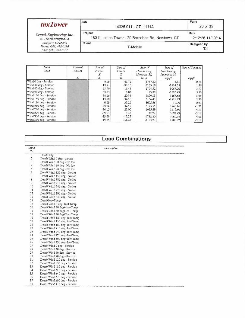
Job Page
t~Q~~~ 14025.011 - CT11111A 23 of 35
Centek Engineering Inc. Project Date
63-2 North Branford Rd. 180-ft Lattice Tower- 20 Barnabas Rd, Newtown, CT 12:12:26 11/10/14Branford, CT0640S Client Designed by
Phone: (203) 488-OS80 T-MobileFAX.• (l03) 488-8587 TJ L
Load Vertical Sum of Sum of Sum of Sum of Sum of TorquesCase Forces Forces Forces Overturning Overturning
X Z Moments, M Moments, MK K K kip ft kip-ft kip-ft
Wind 0 deg -Service 0.09 -41.71 -3787.52 -8.14 -0.78Wind 30 deg -Service 19.91 -3436 3133.19 -1814.58 1.56Wind 60 deg -Service 33.70 -19.43 -1764.52 -3067.20 3.73Wind 90 deg -Service 39.53 0.03 13.89 -3590.43 5.10Wind 120 deg -Service 36.06 20.84 1899.18 -3267.62 5.08Wind 150 deg -Service 19.88 34.50 3166.43 -1821.29 3.30Wind 180 deg -Service -0.09 39.21 3605.66 10.70 0.93Wind 210 deg -Service -20.04 34.59 3175.85 1840.16 -1.76Wind 240 deg -Service -36.15 21.00 1915.49 3279.60 -430Wind 270 deg -Service -39.53 022 32.72 3592.99 -5.10Wind 300 deg -Service -33.60 -19.27 -1748.20 306034 -4.66Wind 330 deg -Service -19.75 -34.27 -3123.77 1800.82 -3.10
Load Combinations_,.~,_
Comb. Desc~~iptionNo.1 Dead Only2 Dead+Wind 0 deg - No Ice3 Dead+Wind 30 deg -No Ice4 Dead+Wind 60 deg - No Ice5 Dead+Wind 90 deg - No Ice6 Dead+Wind 120 deg - No Ice7 Dead+Wind 150 deg - No Ice8 Dead+Wind 180 deg - No Ice9 Dead+Wind 210 deg - No Ice10 Dead+Wind 240 deg - No Ice11 Dead+Wind 270 deg - No Ice12 Dead+Wind 300 deg - No Ice13 Dead+Wind330deg-No Ice14 Dead+Ice+TempIS Dead+Wind 0 deg+Ice+Temp16 Dead+Wind 30 deg+Ice+Temp17 Dead+Wind 60 deg+Ice+Temp18 Dead+Wind 90 deg+Ice+Temp19 Dead+Wind 120 deg+Ice+Temp20 Dead+Wind 150 deg+Ice+Temp21 Dead+Wind 180 deg+Ice+Temp22 Dead+Wind 210 deg+Ice+Temp23 Dead+Wind 240deg+Ice+Temp24 Dead+Wind 270 deg+Ice+Temp25 Dead+Wind 300 deg+Ice+Temp26 Dead+Wind 330 deg+Ice+Temp27 Dead+Wind 0 deg -Service28 Dead+Wind 30 deg -Service29 Dead+Wind 60 deg -Service30 Dead+Wind 90 deg -Service31 Dead+Wind 120 deg -Service32 Dead+Wind 150 deg -Service33 Dead+W~d 180 deg -Service34 Dead+Wind 210 deg -Service35 Dead+Wind 240 deg -Service36 Dead+Wind 270 deg -Service37 Dead+Wind 300 deg -Service38 Dead+Wind 330 deg -Service
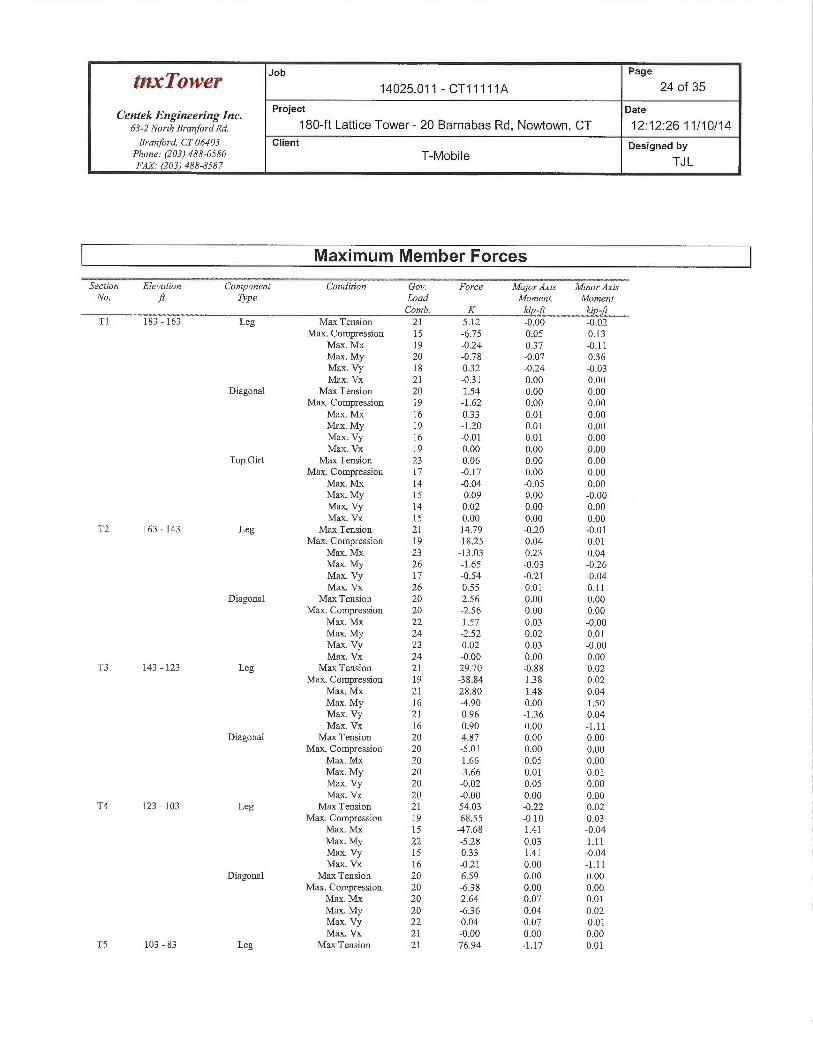
Job Page
~1~~`TO'W~l~ 14025.011 - CT11111A 24 of 35
Centek Engineering Inc. Project Date
63-1 NorthBranforaxa. 180-ft Lattice Tower- 20 Barnabas Rd, Newtown, CT 12:12:26 11/10/14Branford, CT 06405 Client Designed by
Phone: (203)488-0580 T-Mobile TJLFAX.• (203) 488-8587
Maximum Member Forces~~__z_ ---s- _a.~ ~. - -__ :. __----
Section Elevation Component Condition Gov. Force Major Axis Minor AxisNo. ft Type Load Moment Moment
Comb. K kip-ft kip-ftT1 183 -163 Leg Max Tension 21 5.12 -0.00 -0.02
Max. Compression 15 -6.75 0.05 0.13Max. Mx 19 -0.24 0.37 -0.11Marc. My 20 -0.78 -0.07 036Marc. Vy 18 032 -0.24 -0.03Max. Vx 21 -0.31 0.00 0.00
Diagonal Max Tension 20 1.54 0.00 0.00Marc. Compression 19 -1.62 0.00 0.00
Max. NLY 16 033 0.01 0.00Max. My 19 -1.20 0.01 0.00Max. Vy 16 -0.01 0.01 0.00Max. Vx 19 0.00 0.00 0.00
Top Gut Max Tension 23 0.06 0.00 0.00Max. Compression 17 -0.17 0.00 0.00
Max. Mx 14 -0.04 -0.05 0.00Max. My 15 -0.09 0.00 -0.00Max Vy 14 0.02 0.00 0.00Max. Vx 15 0.00 0.00 0.00
T2 163 -143 Leg Maas Tension 21 14.79 -0.20 -0.01Mas. Compression 19 -18.25 0.04 0.01
Max. Mx 23 -13.03 0.23 0.04Max. My 26 -1.65 -0.03 -026Max. Vy 17 -0.54 -0.21 -0.04Max. Vx 26 0.55 0.01 0.11
Diagonal Max Tension 20 2.56 0.00 0.00MaJc. Compression 20 -2.56 0.00 0.00
Max. Mx 22 1.57 0.03 -0.00Max. My 24 -2.52 0.02 0.01Max. Vy 22 0.02 0.03 -0.00Max. Vx 24 -0.00 0.00 0.00
T3 143 -123 Leg Max Tension 21 29.70 -0.88 0.02Max. Compression 19 -38.84 1.38 0.02
Maas. Mx 21 28.80 1.48 0.04Max. My 16 -4.90 0.00 1.50Max. Vy 21 0.96 -136 0.04Max. Vx 16 0.90 0.00 -1.11
Diagonal Max Tension 20 4.87 0.00 0.00Mas. Compression 20 -5.01 0.00 0.00
Max. Mx 20 1.66 0.05 0.00Maas. My 20 -3.66 0.01 0.01Max. Vy 20 -0.02 0.05 0.00Max. Vx 20 -0.00 0.00 0.00
T4 123 -103 Leg Max Tension 21 54.03 -0.22 0.02Max. Compression 19 -68.55 -0.10 0.03
Max. Mx 15 X7.68 1.41 -0.04Max. My 22 -5.28 0.03 1.11Max. Vy 15 033 1.41 -0.04Max. Vx 16 -0.21 0.00 -1.11
Diagonal Max Tension 20 6.59 0.00 0.00Marc. Compression 20 -6.38 0.00 0.00
Max. Mx 20 2.64 0.07 0.01Max. My 20 -636 0.04 0.02Max. Vy 22 0.04 0.07 -0.01Max. Vx 21 -0.00 0.00 0.00
TS 103 - 83 Leg Max Tension 21 76.94 -1.17 0.01
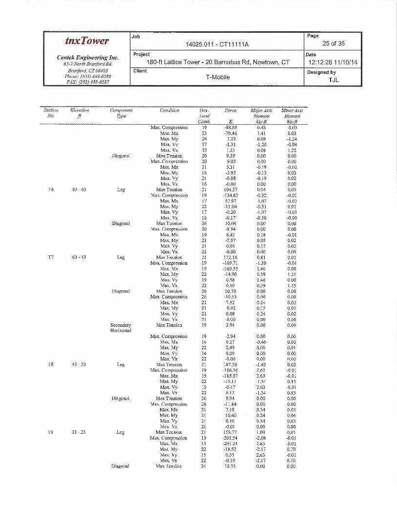
Job Page
tnxTowe~ 14025.011 - CT11111A 25 of 35
Centek Engineering Inc. Project Date
63-2 NorthBranfo.ana. 180-ft Lattice Tower- 20 Barnabas Rd, Newtown, CT 12:12:26 11/10/14Branford, CT 06405 Client Designed by
Phone: (203)488-0580 T-MobileFAX.• (203) 488-8587 TJ L
_ _ _ _ ~~Section Elevation Component Condition Gov. Force Major Axis Minor.LrisNo. ft Type Load Moment Moment
Comb. K kdp-ft kip-fiMa1c. Compression 19 -98.80 0.48 -0.03
Max. Mx 23 -79.46 1.41 0.03Max. My 26 -7.22 0.09 -1.24Max. Vy 17 -131 -120 -0.04Max. Vx 22 1.23 0.08 1.22
Diagonal Max Tension 20 9.29 0.00 0.00Max. Compression 20 -9.02 0.00 0.00
Max. Mx 21 531 -0.19 -0.02Max. My 16 -3.92 -0.13 0.03Max. Vy 21 -0.08 -0.19 0.02Max. Vx 16 -0.00 0.00 0.00
T6 83 - 63 Leg Max Tension 21 104.57 0.04 0.03Max. Compression 19 -134.62 -032 -0.01
Max. Mx 17 87.97 -1.07 -0.03Max. My 22 -11.04 -031 0.91Max. Vy 17 -0.20 -1.07 -0.03Max. Vx 16 -0.17 -0.30 -0.90
Diagonal Max Tension 26 10.06 0.00 0.00Max. Compression 20 -9.94 0.00 0.00
Max. NUc 19 8.43 0.18 -0.01Max. My 21 -7.97 0.08 0.02Max. Vy 21 0.06 0.17 0.02Max. Vx 21 -0.00 0.00 0.00
T7 63 -43 Leg Max Tension 21 132.16 0.81 0.01Max. Compression 19 -169.71 -130 -0.01
Max. Mx 19 -169.55 1.46 0.00Max. My 22 -14.90 039 1.25Max. Vy 19 0.58 1.46 0.00Max. Vx 22 0.40 0.39 1.25
Diagonal Max Tension 26 10.70 0.00 0.00Max. Compression 26 -10.53 0.00 0.00
Max. Mx 21 732 0.24 0.02Max. My 21 -8.92 0.15 0.03Max. Vy 21 0.08 0.24 0.02Max. Vx 21 -0.00 0.00 0.00
Secondary Max Tension 19 2.94 0.00 0.00Horizontal
Max. Compression 19 -2.94 0.00 0.00Max. Mx 14 0.27 -0.46 0.00Max. My 22 2.49 0.00 0.01Max. Vy 14 0.09 0.00 0.00Max. Vx 22 -0.00 0.00 0.00
T8 43 - 33 Leg Max Tension 21 14730 -1.45 0.02Mas. Compression 19 -186.56 2.62 -0.01
Max. Mx 15 -185.57 2.63 -0.01Max. My 22 -15.11 -134 0.83Max. Vy I S -0.47 2.63 -0.OlMax Vx 22 0.12 -134 0.83
Diagonal Max Tension 26 9.94 0.00 0.00Max. Compression 26 -11.84 0.00 0.00
Max. Mx 21 7.18 0.34 0.03Mme. My 21 -10.40 0.24 0.04Max. Vy 21 0.10 034 0.03Max. Vx 21 -0.01 0.00 0.00
T9 33 - 23 Leg Maas Tension 21 158.77 1.09 0.01Max. Compression 19 -205.54 -2.08 -0.01
Max. Mx 15 -204.24 2.63 -0.01Max. My 22 -18.52 -2.17 0.70Max Vy 15 0.55 2.63 -0.01Max. Vx 22 -0.10 -2.17 0.70
Diagonal Max Tension 24 1233 0.00 0.00
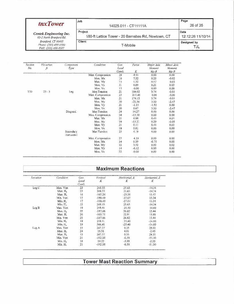
Job Page
tf~x~OW~Y 14025.011 - CT11111A 26 of 35
CentekEngineeringlnc. Project Date
63-zNorrhB,~anfo~~and. 180-ft Lattice Tower- 20 Barnabas Rd, Newtown, CT 12:12:26 11/10/14Branford, CT 06405 Client Designed by
Phone: (203) 488-0580 T-MobileFAX. (203) 488-8587 TJ L
Section Elevation Component Condition Gov. Force Major Axis MinortLzisNo. ft Type Load Moment Moment
Comb. K kip ft kip-ftMaas. Compression 24 -9.91 0.00 0.00
Max. Mx 10 7.52 0.23 -0.02Max. My 15 1:32 0.17 -0.03Max. Vy 21 0.09 0.21 0.03Max. Vx 15 -0.60 0.00 0.00
T10 23 - 3 Leg Max Tension 21 184.02 3.74 -0.01Marc. Compression 23 -241.48 -0.00 -0.00
Max.IvLY 21 174.15 3.74 -0.01Max. My 20 -21.56 3:.10 -2.47Max. Vy 21 -1.15 -1.92 0.00Max. Vx 20 0.67 3.10 -2,47
Diagonal Max Tension 24 14.27 0.00 0.00Max. Compression 24 -1330 0.00 0.00
Max Mx 21 6.98 0.43 0:03Max. My 18 -1321 0.29 -0.05Max. Vy 21 0.11 0.43 0.03Max. Vx 18 0.01 0.00 0.00
Secondary Mas Tension 23 4.19 0.00 0.00Horizontal
Max. Compression 23 -4.19 0.00 0.00Mme. Mx 14 0.39 -0.75 0.00Maas. My 22 3.52 0.00 0.02Max. Vy 14 -0.12 0.00 0.00Max. Vx 22 -0.00 0.00 0.00
Maximum Reactions~~_ ,.~__ _ _ __~,o:
Location Condition Gov. Vertical Horizontal, X Horizontal, ZLoad K K KComb.
Leg C Max. Vert 23 248.55 25.65 -14.34Max. Hx 23 248.55 25.65 -1434Max H~ 16 -165.26 -23.29 15.47Min. Vert 17 -188.49 -27.07 15.24Min. Hx 17 -188.49 -27.07 15.24Min. H~ 23 248.55 25.65 -14.34
Legg Max. Vert 19 248.41 -25.40 -14.60Max. Hx 25 -187.06 26.82 15.44Max. Hz 26 -163.71 22.91 15:88Min. Vert 25 -187.06 26.82 15.44Min. Hx 19 248.41 -25.40 -14.60Min. H~ 19 248.41 -25:40 -14.60
Leg A Max. Vert 15 24737 035 2931Maas. H, 24 18.31 4.01 -2.45Max. H~ 15 247.37 035 29.31Min. Vert 21 -19238 -030 -3130Min. Hx 18 19.22 -3.99 -233Min. H~ 21 -19238 -030 -31.30
Tower Mast Reaction Summary
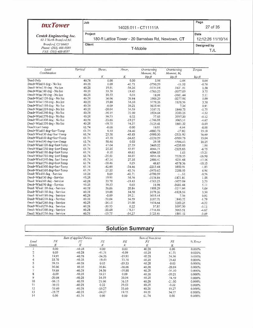
Job Page
tt~a~~'ower 14025.011 - CT11111A 27 of 35
Centek Engineering Inc. Project gate
63-2 NorthBranforaxa. 180-ft Lattice Tower- 20 Barnabas Rd, Newtown, CT 12:12:26 11/10/14Branford, CT 06405 Client Designed by
Phone: (203)488-0580 T-Mobile TJLFAX.• (203) 488-8587
_ -- - - wLoad Vertical Shearx Shear, Overturning Overturning Torque
Combination Moment, M Moment, M,K K K kiR-~ ~P-}~ ~P-It
Dead Only 40.28 0.00 0.00 5.96 -2.06 0.00Dead+Wind 0 deg - No Ice 40.28 0.09 -41.71 3790.59 -11.52 -0.76Dead+Wind 30 deg - No Ice 40.28 19.91 -34.36 -3134.84 -1821.81 1.58Dead+Wind 60 deg -No Ice 40.28 33.70 -19.43 -1763.23 -3077.09 3.75Dead+Wind 90 deg -No Ice 40.25 39.53 0.03 18.98 -3601.44 5.11Dead+Wind 120 deg - No Ice 40.28 36.06 20.84 1908.29 -3277.96 5.09Dead+Wind 150 deg - No Ice 40.28 19.88 34.50 317826 -1828.56 3.30Dead+Wind 180 deg-No Ice 4028 -0.09 39.21 3618.44 736 0.91Dead+Wind 210 deg - No Ice 4028 -20.04 34.59 3187.71 1840.75 -1.79Dead+Wind 240 deg - No Ice 40.28 -36.15 21.00 1924.64 3283.25 -432Dead+Wind 270 deg-No Ice 40.28 -39.53 0.22 37.85 359730 -5.12Dead+Wind 300 deg - No Ice 4028 -33.60 -19.27 -1746.88 3063.51 -4.67Dead+Wind 330 deg - No Ice 40.28 -19.75 -3427 -3125.41 180132 -3.09Dead+Ice+Temp 61.74 -0.00 -0.00 16.01 -8.04 -0.00Dead+Wind 0 deg+Ice+Temp 61.74 0.10 -54.40 -4882.73 -17.82 15.19Dead+Wind 30deg+Ice+Temp 61.74 2538 -43.83 -3980.30 -2321.92 16.69Dead+Wind 60 deg+Ice+Temp 61.74 42.70 -24.62 -2230.29 -3909.73 15.04Dead+Wind 90 deg+Ice+Temp 61.74 50.46 0.03 29.39 X594.43 10.15Dead+Wind 120 deg+Ice+Temp 61.74 47.04 27.19 2469.52 X238.05 1.96Dead+Wind 150 deg+Ice+Temp 61.74 2535 43.97 4044.71 -2328.83 -6.75Dead+Wind 180 deg+Ice+Temp 61.74 -0.10 49.61 4584.85 1.65 -13.21Dead+Wind 210 deg+Ice+Temp 61.74 -25.51 44.07 4054.48 2329.53 -16.90Dead+Wind 240 deg+Ice+Temp 61.74 X7.14 2735 2486.41 4231.68 -17.16Dead+Wind 270 deg+Ice+Temp 61.74 -50.46 0.23 48.85 457836 -10.15Dead+Wind 300deg+Ice+Temp 61.74 X2.60 -24.46 -2213.48 3883.91 -1.83Dead+Wind 330 deg+Ice+Temp 61.74 -25.22 -43.74 -3970.62 2288.93 6.96Dead+Wind 0 deg -Service 40.28 0.09 -41.71 -3790.59 -11.52 -0.76Dead+Wind 30 deg -Service 40.28 19.91 -3436 -3134.84 -1821.81 1.58Dead+Wind 60 deg -Service 4028 33.70 -19.43 -1763.23 -3077.09 3.75Dead+Wind 90 deg -Service 40.28 39.53 0.03 18.98 -3601.44 5.11Dead+Wind 120 deg -Service 40.28 36.06 20.84 190829 -3277.96 5.09Dead+Wind 150 deg -Service 40.28 19.88 34.50 317826 -1828.56 330Dead+Wind 180 deg -Service 40.28 -0.09 3921 3618.44 736 0.91Dead+Wind 210 deg -Service 40.28 -20.04 34.59 3187.71 1840.75 -1.79Dead+Wind 240 deg -Service 40.28 -36.15 21.00 1924.64 3283.25 -432Dead+Wind 270 deg -Service 4028 -39.53 0.22 37.85 359730 -5.12Dead+Wind 300 deg -Service 40.28 -33.60 -19.27 -1746.88 3063.51 -4.67Dead+Wind 330 deg -Service 40.28 -19.75 -34.27 -3125.41 180132 -3.09
Solution Summary
Sum ofApplied Forces Sum of ReactionsLoad PX PY PZ PX PY PZ %ErrorComb. K K K K K K
1 0.00 -40.28 0.00 0.00 40.28 0.00 0.000%2 0.09 -40.28 X1.71 -0.09 40.28 41.71 0.000%3 19.91 -40.28 -3436 -19.91 40.28 3436 0.000%4 33.70 -40.28 -19.43 -33.70 40.28 19.43 0.000%5 39.53 -40.28 0.03 -39.53 40.28 -0.03 0.000%6 36.06 X0.28 20.84 36.06 40.28 -20.84 0.000%7 19.88 -40.28 34.50 -19.88 40.28 -34.50 0.000%8 -0.09 -40.28 39.21 0.09 40.28 -39.21 0.000%9 -20.04 -40.28 34.59 20.04 40.28 -34.59 0.000%10 -36.15 -40.28 21.00 36.15 40.28 -21.00 0.000%11 -39.53 X0.28 0.22 39.53 40.28 -0.22 0.000%12 -33.60 X0.28 -19.27 33.60 40.28 19.27 0.000%13 -19.75 -40.28 -34.27 19.75 40.28 34.27 0.000%14 0.00 -61.74 0.00 0.00 61.74 0.00 0.000%
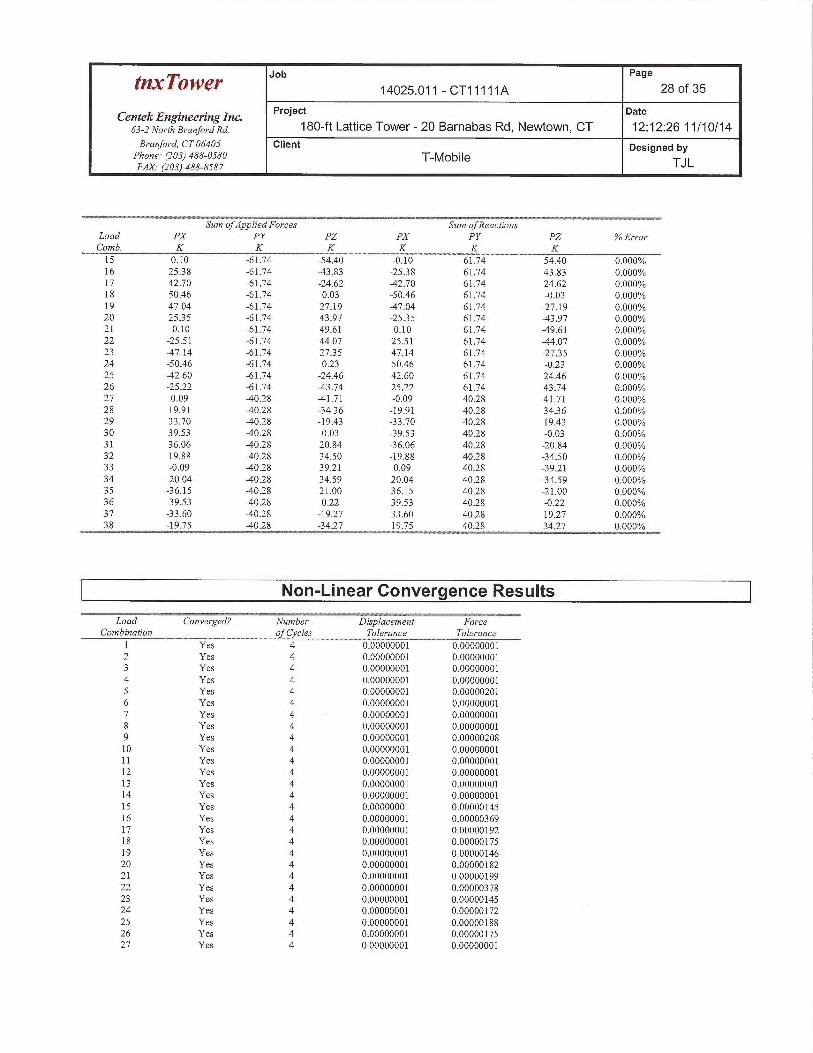
Job Page
tnxTowe~ 14025.011 - CT11111A 28 of 35
Centek Engineering Inc. Project Date
63-2No~~ahBYanfo~~ana. 180-ft Lattice Tower - 20 Barnabas Rd, Newtown, CT 12:12:26 11/10/14B~~anford, CT 06405 Client Designed by
Phone: (203J 488-0580 T-MOblleFAX. (203) 488-8587 TJL
Sum of Applied Forces Sinn of ReactionsLoad PX PY PZ PX PY PZ %ErrorComb. K K K K K K15 0.10 -61.74 -54.40 -0.10 61.74 54.40 0.000%16 25.38 -61.74 -43.83 -2538 61.74 43.83 0.000%17 42.70 -61.74 -24.62 -42.70 61.74 24.62 0.000%18 50.46 -61.74 0.03 -50.46 61.74 -0.03 0.000%19 47.04 -61.74 27.19 -47.04 61.74 -27.19 0.000%20 2535 -61.74 43.97 -2535 61.74 -43.97 0.000°/a21 -0.10 -61.74 49.61 0.10 61.74 -49.61 0.000%22 -25.51 -61.74 44.07 25.51 61.74 -44.07 0.000%23 -47.14 -61.74 2735 47.14 61.74 -2735 0.000%24 -50.46 -61.74 0.23 50.46 61.74 -0.23 0.000%25 -42.60 -61.74 -24.46 42.60 61.74 24.46 0.000%26 -25.22 -61.74 X3.74 25.22 61.74 43.74 0.000%27 0.09 -40.28 X1.71 -0.09 40.28 41.71 0.000%28 19.91 -40.28 -3436 -19.91 40.28 34.36 0.000%29 33.70 -40.28 -19.43 -33.70 40.28 19.43 0.000%30 39.53 -40.28 0.03 -39.53 40.28 -0.03 0.000%31 36.06 -40.28 20.84 -36.06 40.28 -20.84 0.000%32 19.88 -40.28 34.50 -19.88 40.28 -34.50 0.000%33 -0.09 -40.28 39.21 0.09 40.28 -39.21 0.000%34 -20.04 X0.28 34.59 20.04 40.28 -34.59 0.000%35 -36.15 -40.28 21.00 36.15 40.28 -21.00 0.000%36 -39.53 -40.28 0.22 39.53 40.28 -0.22 0.000%37 -33.60 -40.28 -19.27 33.60 40.28 19.27 0.000%38 -19.75 -40.28 -34.27 19.75 40.28 34.27 0.000%
Non-Linear Convergence Results. _ _..
Load Converged? Number Disylacement ForceCombination of Cycles Tolerance Tolerance
1 Yes 4 0.00000001 0.000000012 Yes 4 0.00000001 0.000000013 Yes 4 0.00000001 0.000000014 Yes 4 0.00000001 0.000000015 Yes 4 0.00000001 0.000002016 Yes 4 0.00000001 0.000000017 Yes 4 0.00000001 0.000000018 Yes 4 0.00000001 0.000000019 Yes 4 0.00000001 0.0000020810 Yes 4 0.00000001 0.0000000111 Yes 4 0.00000001 0.0000000112 Yes 4 0.00000001 0.0000000113 Yes 4 0.00000001 0.0000000114 Yes 4 0.00000001 0.0000000115 Yes 4 0.00000001 0.0000014516 Yes 4 0.00000001 0.0000036917 Yes 4 0.00000001 0.0000019218 Yes 4 0.00000001 0.0000017519 Yes 4 0.00000001 0.0000014620 Yes 4 0.00000001 0.0000018221 Yes 4 0.00000001 0.0000019922 Yes 4 0.00000001 0.0000037823 Yes 4 0.00000001 0.0000014524 Yes 4 0.00000001 0.0000017225 Yes 4 0.00000001 0.0000018826 Yes 4 0.00000001 0.0000017527 Yes 4 0.00000001 0.00000001
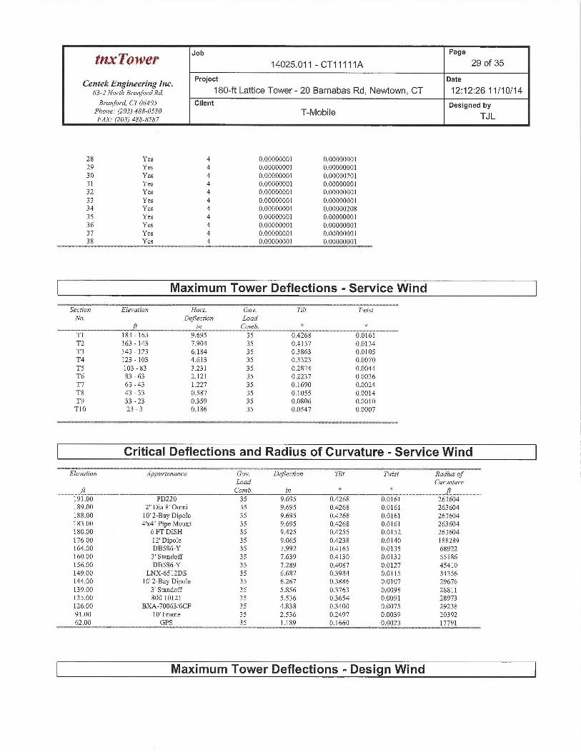
Job Page
tax ~OWeY 14025.011 - CT 11111 A 29 of 35
CentekEngineeringlnc. Project Date
63-z No7~rh a~-anfo,-axa. 180-ft Lattice Tower - 20 Barnabas Rd, Newtown, CT 12:12:26 11/10/14Branfm~d, CT 06405 Client Designed by
Phone: (203) 488-0580 T-MobileF~~ ~zo3~ 4ss-sss~ TJL
28 Yes 4 0.00000001 0.0000000129 Yes 4 0.00000001 0.0000000130 Yes 4 0.00000001 0.0000020131 Yes 4 0.00000001 0.0000000132 Yes 4 0.00000001 0.0000000133 Yes 4 0.00000001 0.0000000]34 Yes 4 0.00000001 0.0000020835 Yes 4 0.00000001 0.0000000136 Yes 4 0.00000001 0.0000000137 Yes 4 0.00000001 0.0000000138 Yes 4 0.00000001 0.00000001
Maximum Tower Deflections -Service Wind
~Section~ ~ ElevationT ~ Horz. Gov. Tilt TwistNo. Deflection Load
ft in Comb. °
T1 183 - 163 9.695 35 0.4268 0.0161T2 163 - 143 7.904 35 0.4157 0.0134T3 143 - 123 6.184 35 03863 0.0105T4 123 - 103 4.613 35 0.3323 0.0070TS 103 - 83 3.231 35 0.2874 0.0044T6 83 - 63 2.121 35 0.2237 0.0036T7 63 - 43 1.227 35 0.1690 0.0024T8 43 - 33 0.587 35 0.1055 0.0014T9 33-23 0359 35 0.0806 0.0010T10 23 - 3 0.186 35 0.0547 0.0007
Critical Deflections and Radius of Curvature -Service Wind
Elevation Appurtenance Gov. Deflection Tilt Twist Radius ofLoad Curvature
ft Comb. in ft
191.00 PD220 35 9.695 0.4268 0.0161 263604189.00 2" Dia 8' Omni 35 9.695 0.4268 0.0161 263604188.00 10' 2-Bay Dipole 35 9.695 0.4268 0.0161 263604183.00 4'x4" Pipe Mount 35 9.695 0.4268 0.0161 263604180.00 6 FT DISH 35 9.425 0.4255 0.0152 263604176.00 12'Dipole 35 9.065 0.4238 0.0140 188289164.00 DB586-Y 35 7.992 0.4165 0.0135 68922160.00 3' Standoff 35 7.639 0.4130 0.0132 55186156.00 DB586-Y 35 7.289 0.4087 0.0127 45410149.00 LNX-6512DS 35 6.687 03984 0.0115 34356144.00 10' 2-Bay Dipole 35 6.267 0.3886 0.0107 29676139.00 3' Standoff 35 5.856 03763 0.0098 28811135.00 80010121 35 5.536 03654 0.0091 28973126.00 BXA-70063/6CF 35 4.838 03400 0.0075 2923891.00 10' Frame 35 2.536 0.2497 0.0039 2039262.00 GPS 35 1.189 0.1660 0.0023 17791
Maximum Tower Deflections -Design Wind
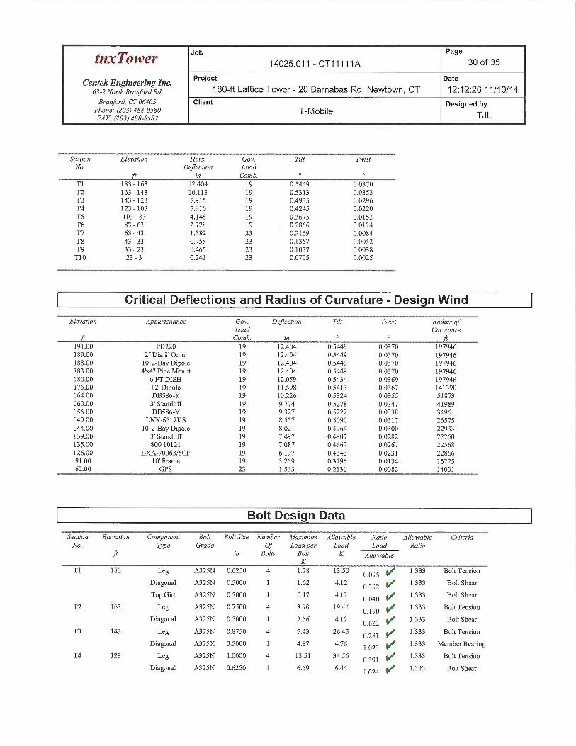
tnxTower Jib
Page
14025.011 - CT 11111 A 30 of 35
CentekEngineeringlnc. Project gate
63-zNo~~rnBYaMforaxa. 180-ft Lattice Tower- 20 Barnabas Rd, Newtown, CT 12:12:26 11/10/14Branford, CT 06405 Client Designed by
Phone: (203) 488-0580 T-MobileFAX.• (203) 488-8587 TJ L
--._~ __ _ --~. _~__._ __ __r_ .___..Section Elevation Horz. Gov. Tilt TwistNo. Deflection Load
ft in Comb. °T1 183 - 163 12.404 19 0.5449 0.0370T2 163 -143 10.113 19 0.5313 0.0353T3 143 - 123 7.915 19 0.4935 0.0296T4 123 - 103 5.910 19 0.4245 0.0220TS 103 - 83 4.148 19 0.3675 0.0153T6 83 - 63 2.728 19 0.2866 0.0124T7 63-43 1.582 23 0.2169 0:0084T8 43-33 0.758 23 0.1357 0.0052T9 33 -23 0.465 23 0:1037 0.0038T10 23-3 0.241 23 0.0705 0.0025
Critical Deflections and Radius of Curvature -Design Wind
Elevation ~ Appw~tenance m v Gov. Deflection ~s ~ Tilt Twist Radius ofLoad Curvature
ft Comb. zn ft191.00 PD220 19 12.404 0.5449 0.0370 19794fi189A0 2" Dia 8' Omni 19 12.404 0.5449 0.0370 197946188.00 10'2-Bay Dipole 19 12.404 0.5449 0.0370 197946183.00 4'x4" Pipe Mount 19 12.404 0.5449 0.0370 197946180,00 6 FT DISH 19 12.059 0.5434 0.0369 197946176.00 12' Dipole 19 11.598 0.5413 0.0367 141390164.00 DB586-Y 19 10.226 0.5324 0.0355 51873160.00 3' Standoff 19 9.774 O.SZ78 0.0347 41989156.00 DB586-Y 19 9327 0.5222 0.0338 34961149:00 LNX-6512DS 19 8.557 0.5090 0.0317 26575144.00 10' 2-Bay Dipole 19 8.021 0.4964 0.0300 22933139.00 3' Standoff 19 7.497 0.4807 0.0282 22260135.00 80010121 19 7.087 0.4667 0.0267 22568126,00 BXA-70063/6CF 19 6.197 0.4343 0.0231 2286691.00 10' Frame 19 3.259 03196 0,0134 1622562.00 GPS 23 1.533 0.2130 0.0082 14001
Bolt Design Data
Section Elevation Component Bolt Bolt Size Number Maximum Allowable Ratio Allowable CriteriaNo. Type Grade Of Loadpe~^ Load Load Ratio
ft in Bolts BoZG K AllowableK
Tl 183 Leg A325N 0.6250 4 1.28 13.50 0.095 1~
1.333 Bolt Tension
Diagonal A325N 0.5000 1 1.62 4.12 0392 1~
1333 Bolt Sheaz
Top. Gut A325N 0.5000 1 0.17 4.12 0.040 1+~
1333 Bolt Shear
T2 163 Leg A325N 0.7500 4 3.70 19.44 0.190 ~
1.333 Bolt Tension
Diagonal A325N 0.5000 1 2.56 4.12 0 622 1~ 1.333 Bolt Shear
T3 143 Leg A325N 0.8750 4 7.43 26.45 ~ 281 ~/ 1.333 Bolt Tension
Diagonal A325X 0..5000 1 4.87 4.76 1.023 4~ 1333 Member Bearing
T4 123 Leg A325N 1.0000 4 13.51 34.56 0391 f~ 1.333 Bolt Tension
Diagonal A325N 0.6250 1 6.59 6.44 1.024 V~
1.333 Bolt Shear
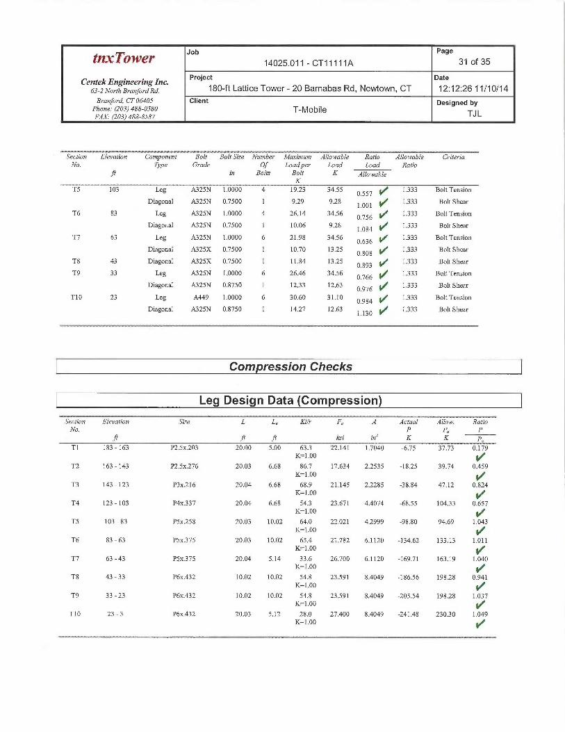
Job Page
tnx~'ower 14025.011 - CT11111A 31 of 35
CentekEngineeringlnc. Project gate
6s-z No~r~B~~anfoYaxa. 180-ft Lattice Tower - 20 Barnabas Rd, Newtown, CT 12:12:26 11/10/14Branford, CT 06405 Client Designed by
Phone: (203) 488-0580 T-MobileFAX. (203) 488-8587 TJ L
Section Elevation Component Bolt Bolt Szze Number Maximum Allowable Ratio Allowable C~~iteriaNo. Type Grade Of Load per Load Load Ratio
ft in Bolts Bolt K AllowableK
TS 103 Leg A325N 1.0000 4 19.23 34.55 0.557 ~
1.333 Bolt Tension
Diagonal A325N 0.7500 1 929 9.28 1:001 4f 1.333 Bolt Shear
T6 83 Leg A325N 1.0000 4 26.14 34.56 0.756 l~
1333 Bolt Tension
Diagonal A325N 0.7500 1 10:06 9.28 1.084 1f
1.333 Bolt Shear
T7 63 Leg A325N 1.000d 6 21.98 34.56 0.636 ~
1.333 Bolt Tension
Diagonal A325X 0.7500 1 10.70 13.25 ~ 808 ~ 1.333 Bolt Shear
T8 43 Diagonal A325X 0.7500 1 11.84 13:25 Q 893 y/ 1333 Bolt Sheaz
T9 33 Leg A325N 1.0000 6 26.46 34.56 0.766
1.333 Bolt Tension
Diagonal A325N 0.8750 1 1233 12.63 0.976 ~
1333 Bolt Shear
T10 23 Leg A449 1.0000 6 30.60 31.10 0.984 1~
1333 Bolt Tension
Diagonal A325N 0.8750 1 14.27 12.63 1.130 ~
1333 Bolt Shear
Compression Checks
Leg Design Data (Compression)
Section Elevation S7ze ~ L L„ Klh~ F A Actual Allow. RatioNo. P Pa P
ft ft ft ksi in' K K pa
T1 183 -163 P2.Sx.203 20.00 5.00 633 22.141 1.7040 -6.75 37.73 0.179K=1..00 ~"
T2 163 -143 P2.Sx.276 20.03 6.68 86.7 17.634 2.2535 -18.25 39.74 0.459K=1.00
T3 143 -123 P3x.216 20.04 6.68 68.9 21.145 2.2285 -38.84 47.12 0:824K=1.00 ~"
T4 123 -103 P4x337 20.04 6.68 54.3 23.671 4.4074 -68.55 10433 0.657K-1A0 ~f
TS 103 - 83 PSx258 20.03 10.02 64.0 22.021 4.2999 -98.80 94.69 1.043K=1.00
T6 83 - 63 PSx375 20.03 10.02 65.4 21.782 61120 -134.62 133.13 1.011K=1:00
T7 63 - 43 PSx375 20.04 5.14 33.6 26.700 6.1120 -169.71 163.19 1.040K=1.00 ~ f
T8 43 - 33 P6x.432 10.02 10.02 54.8 23.591 8.4049 -186.56 198.28 0.941K=1.00
T9 33 -23 P6x.432 10.02 10.02 54.8 23.591 8.4049 -205.54 198.28 1.037K=1.00
T10 23 -3 P6x.432 20,03 5.12 28.0 27.400 8.4044 -241.48 23030 1.049K=1.00
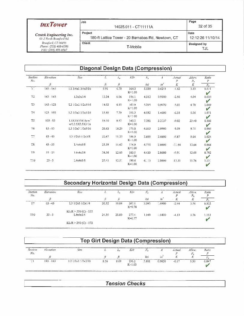
Job Page
tnxTower 14025.011 - CT11111A 32 of 35
Centek Engineering Inc. Project Date
63-zNo,~tha~~an}o~~axa. 180-ft Lattice Tower - 20 Barnabas Rd, Newtown, CT 12:12:26 11/10/14Branford, CT 06405 Client Designed by
Phone: (203) 488-0580 T-Mobile TJLFAX. (203) 488-8587
Diagonal Design Data (Compression)
Section Elevation Srze L L„ Kl/r' F A ~ Actual AZlow. RatioNo. p pa p
ft ft ft ksi inz K K pa
Tl 183 - 163 Ll 3/4x1 3/4x3/16 9.91 4.70 1643 5.530 0.6211 -1.62 3.43 0.471
K=1.00 ~/"
T2 163 - 143 L2x2x1/4 12.24 6.06 186.1 4312 0.9380 -2.56 4.04 0.634K=1.00 ~#
T3 143 - 123 L2 1/2~ 1/2x3/16 14.02 6.93 167.9 5.295 0.9020 -5.01 4.78 1.049K=1.00
T4 123 - 103 L2 1/2x2 1/2x5/16 15.89 7.79 1913 4.082 1.4600 -638 5.96 1.071K=1.00
TS 103 - 83 L3X3X3/16 Reinf 19.10 9.57 143.2 7.281 3.2137 -9.02 23.40 0386w/L2.SX2.SX3/16 K=1.00 ~"
T6 83 - 63 L3 1/2x3 1/2x5/16 20.83 10.29 179.0 4.663 2.0900 -9.59 9.75 0.984K=1.00
T7 63 -43 L3 1/2x3 1/2x3/8 22.67 11.22 196.0 3.888 2.4800 -9.87 9.64 1.024
K=1.00 ~'
T8 43 - 33 L4x4x3/8 23.59 11.62 176.9 4.770 2.8600 -11.84 13.64 0.868K=1.00
T9 33 -23 L4x4x3/8 24.50 12.05 183.5 4.433 2.8600 -9.91 12.68 0.782K=1.00 ~I"
T10 23 -3 L4x4x3/8 25.41 12.51 190.6 4.113 2.8600 -13.31 11.76 1.131K=1.00.
Secondary Horizontal Design Data (Compression)
Section Elevation Saze SL L„ KI/r ~ F A~ ~ctz~al AIZow. RatioNo. P Pa P
ft ft ft ksi an' K K po
T7 63 -43 L3 1/2x3 1/2x1/4 20.32 19.86 267.1 2.093 1.6900 -2.94 3.54 0.832K=0.78 ~f
KL/R> 250 (C) - 133T10 23-3 L4x4x1/4 2435 23.80 277.4 1.940 1.9400 -4.19 3.76 1.113
K=0.77 ~/
KL/R> 250 (C) - 172
Top Girt Design Data (Compression)_~ _ ._ - ~ - -- --- ----~_-__. ~~E z ~~~ _ _ ___ . _ _ ~~~. ~~~~
Section Elevation Size L L„ Klh~ F A Actual Allow. RatioNo. P Pa P
ft ft ft ksi zn' K K pa
T1 183 - 163 L2 1/2~ 1/2x3/16 8.56 8.09 196.2 3.881 0.9020 -0.17 3.50 0.047K=1.00 ~/
Tension Checks
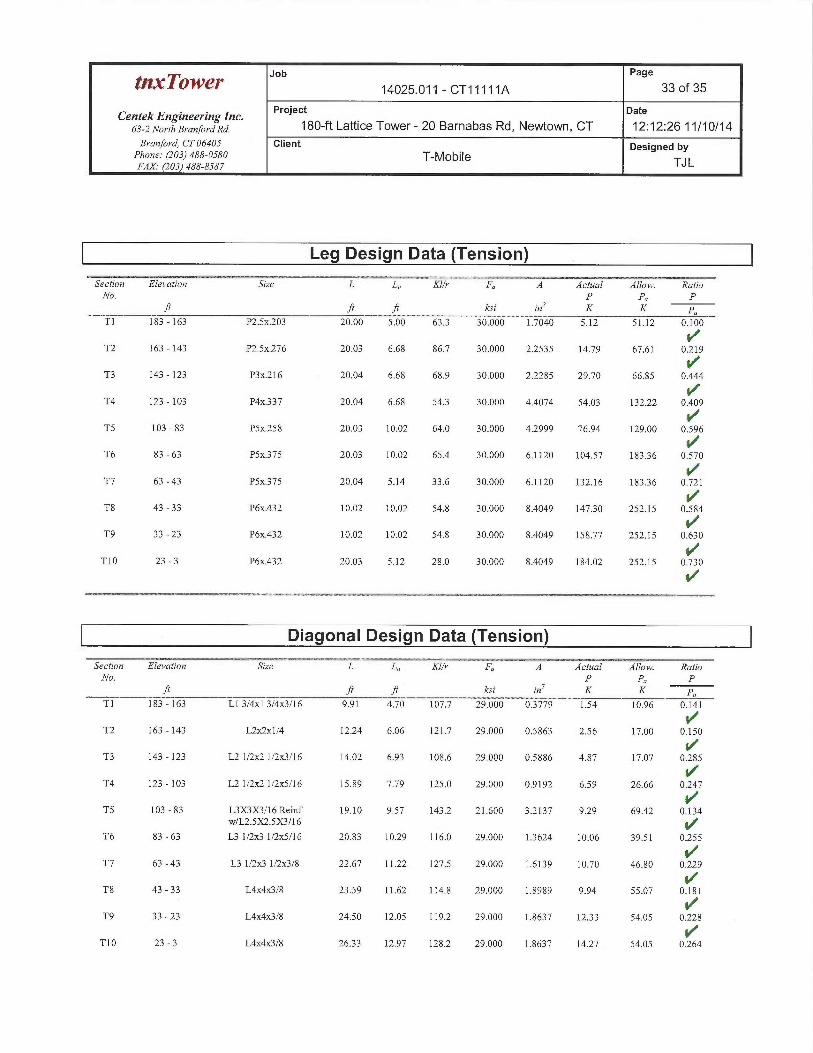
Job Page
t~x~'owe~ 14025.011 - CT11111A 33 of 35
Centek Engineering Inc. Project Date
63-zNo~-rhaYanfo~~axa. 180-ft Lattice Tower- 20 Barnabas Rd, Newtown, CT 12:12:26 11/10/14B~~anford, CT 06405 Client Designed by
Phone: (203) 488-0580 T-MobileFAX• (203) 488-8587 TJL
Leg Design Data (Tension)
Section Elevation Size L L„ Klh^ F A Actual Allow. RatioNo. P Po P
ft ft ft ksi in' K K po
T1 183 - 163 P2.Sx.203 20.00 5.00 63.3 30.000 1.7040 5.12 51.12 0.100
T2 163 - 143 P2.Sx276 20.03 6.68 86.7 30.000 2.2535 14.79 67.61 0.~2/19
4~T3 143 - 123 P3x.216 20.04 6.68 68.9 30.000 2.2285 29.70 66.85 0.444
T4 123 - 103 P4x337 20.04 6.68 543 30.000 4.4074 54.03 132.22 0.409
TS 103 - 83 PSx.258 20.03 10.02 64.0 30.000 4.2999 76.94 129.00 0.596
T6 83 - 63 PSx.375 20.03 10.02 65.4 30.000 6.1120 104.57 183.36 0.570
T7 63 -43 PSx375 20.04 5.14 33.6 30.000 6.1120 132.16 18336 0.721
T8 43 -33 P6x.432 10.02 10.02 54.8 30.000 8.4049 147.30 252.15 0.584
T9 33 -23 P6x.432 10.02 10.02 54.8 30.000 8.4049 158.77 252.15 0.630
T10 23-3 P6x.432 20.03 5.12 28.0 30.000 8.4049 184.02 252.15 0.730
Diagonal Design Data (Tension)
Secfion Elevation Szze L L„ KZ/r F A Actual Allow. RatioNo. P Po P
ft ft ft ksd in' K K pa
Tl 183 -163 Ll 3/4x1 3/4/16 9.91 A.70 107.7 29.000 0.3779 1.54 10.96 0.141
T2 163 - 143 L2ac2x1/4 12.24 6.06 121.7 29.000 0.5863 2.56 17.00 0.150
T3 143 - 123 L2 1/2~ 1/2x3/16 14.02 6.93 108.6 29.000 0.5886 4.87 17.07 0.285
T4 123 - 103 L2 1/2~ 1/2x5/16 15.89 7.79 125.0 29.000 0.9192 6.59 26.66 0.+2~47
YTS 103 - 83 L3X3X3/16 Reinf 19.10 9.57 143.2 21.600 3.2137 9.29 69.42 0..134
w/L2.SX2.SX3/16 ~I
T6 83-63 L31/2x31/2x5/16 20.83 10.29 116.0 29.000 13624 10.06 39.51 0.255
T7 63 -43 L3 1/2x3 1/2x3/8 22.67 11.22 127.5 29.000 1.6139 10.70 46.80 0.229
T8 43 - 33 L4x4x3/8 23.59 11.62 114.8 29.000 1.8989 9.94 55.07 0.181
T9 33 -23 L4x4x3/8 24.50 12.05 119.2 29.000 1.8637 1233 54.05 0.228
T10 23-3 L4x4x3/8 2633 12.97 128.2 29.000 1.8637 14.27 54.05 0.264
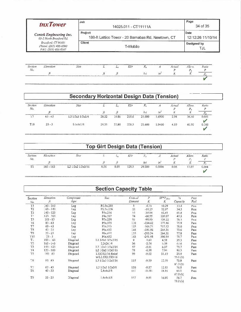
tnxTower Jib Page
14025.011 - CT 11111 A 34 of 35
Centek Engineering Inc. Project Date
63-2No~-ri,B~~anfo~~ana. 180-ft Lattice Tower- 20 Barnabas Rd, Newtown, CT 12:12:26 11/10/14Branford, CT 06405 Client Designed by
Phorse: (203) 488-0580 T-Mobile TJLFAX. (203) 488-8587
Section Elevation Size L L„ Klh~ F A Actual Allow. RatioNo. P Pa P
ft ft ft ksi inZ K K p„
Secondary Horizontal Design Data (Tension)a~~~- - - ----- -- - --_ --~~ - -- - -
Section Elevation Size L L„ KZ/r F A Actual ~ JAllow. RatioNo. P Pa P
ft ft ft ksi ins K K p
T7 63 - 43
T10 23-3
L31/2x31/2x1/4 20.32 19.86 218.6 21.600 1.6900 2.94
L4x4xl/4 24.35 23.80 228.5 21.600 1.9400 4.19
36.50 0.081
1+'41.90 0.100
Top Girt Design Data (Tension)
Section Elevation Size L L„ Kl/r F A Actual Allow. RatioNo. P Pa P
ft ft fl ksi ir2~ K K pa
T1 183 - 163 L2 1/2ac2 1/2x3/16 8.56 8.09 128.3 29.000 0.5886 0.06 17.07 0.004
Section Capacity Table
Section Elevation Component Size Critical P SF*Pano„ % Pass
No. ~ Type Element K K Capacity Fail
T1 183 - 163 Leg P2.Sx.203 3 -6.75 50.29 13.4 PassT2 163 - 143 Leg P2.Sx.276 32 -18.25 52.97 34.5 PassT3 143 - 123 Leg P3x.216 53 -38.84 62.81 61.8 PassT4 123 - 103 Leg P4x337 74 -68.55 139.07 49.3 PassTS 103 - 83 Leg PSx.258 95 -98.80 126.22 783 PassT6 83 - 63 Leg PSx375 110 -134.62 177.46 75.9 PassT7 63 - 43 Leg PSx375 125 -169.71 217.53 78.0 PassT8 43 - 33 Leg P6x.432 146 -186.56 264.31 70.6 PassT9 33 - 23 Leg P6x.432 155 -205.54 26431 77.8 PassT10 23 - 3 Leg P6x.432 163 -241.48 306.99 78.7 PassTl 183 - 163 Diagonal Ll 3/4x1 3/4x3/16 9 -1.62 4.58 353 PassT2 163 - 143 Diagonal L2~x1/4 36 -2.56 539 47.6 PassT3 143 - 123 Diagonal L2 1/2x2 1/2x3/16 57 -5.01 637 78.7 PassT4 123 - 103 Diagonal L2 1/2ac2 1/2x5/16 78 -638 7.94 803 PassTS 103 - 83 Diagonal L3X3X3/16 Reinf 99 -9.02 31.19 28.9 Pass
w/L2.SX2.SX3/16 751 (b)T6 83 - 63 Diagonal L3 1/2x3 1/2x5/16 115 -9.59 12.99 73.8 Pass
813 (b)T7 63-43 Diagonal L31/2x31/2x3/8 130 -9.87 12.85 76.8 PassT8 43 - 33 Diagonal L4x4x3/8 151 -11.84 18.19 65.1 Pass
67.0 (b)T9 33 - 23 Diagonal L4x4x3/8 157 -9.91 16.90 58.7 Pass
73.2 (b)
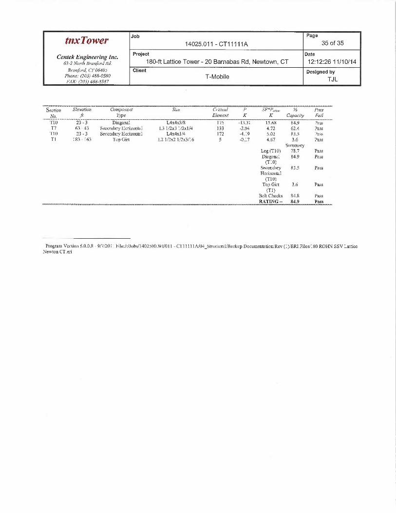
Job Page
~I~~~O~V~Y 14025.011 - CT11111A 35 of 35
Centek Engineering Inc. Project Date
6s-zNoYrhs~~anfo~~aRa. 180-ft Lattice Tower- 20 Barnabas Rd, Newtown, CT 12:12:26 11/10/14Branford, CT 06405 Client Designed by
Phone: (203) 488-0580 T-Mobile TJLFAX (203) 488-8587
Section Elevation Component ~ Sipe Critical P SF*Porto, ~ % Pass
No. ~ Type Element K K Capacity Fail
T10 23 - 3 Diagonal L4x4x3/8 175 -1331 15.68 84.9 PassT7 63 -43 Secondary Horizontal L3 1/2x3 1/2x1/4 133 -2.94 4.72 62.4 PassT10 23-3 Secondary Horizontal L4x4x1/4 172 -4.19 5.02 83.5 PassT1 183 - 163 Top Gut L2 1/2~ 1/2x3/16 5 -0.17 X4.67 3.6 Pass
SummaryLeg (T10) 78.7 PassDiagonal 84.9 Pass(T10)
Secondary 83.5 PassHorizontal(T 10)Top Gut 3.6 Pass(T1)
Bolt Checks 84.8 PassRATING= 84.9 Pass
Program Version 6.0.0.8 - 9/7/2011 Fi]e:J:/Jobs/1402500.WU011 - CT11111A/04_Structural/Backup Documentation/Rev (1)BRI Files/180 ROHM SSV LatticeNewton CT.eri
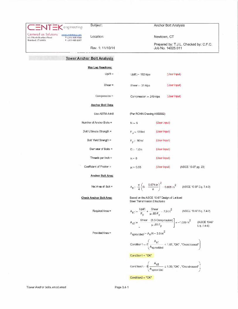
Subject: Anchor Bolt Analysis
~r. ~,,~:~&s~r~~~,r~r ~:~;x~~;~~{},s,•~, Location: Newtown, CTF.4anfard.~7~tdS F.,.tei tikby1~95'1N}
Prepared by: T.J.L. Checked by: C.F.C.Rev. 1: 11/10/14 Job No. 14025.011
Tower Anchor BoltAnalvsis
Mau Leq Reactions:
Uplift =
Shear =
Compression =
Anchor Bolt Data:
Use ASTM A449
Number of Andior Bolts =
Bolt Ultimate Strength =
Bolt veld Strength =
Diameter of Bolts =
Threads perinch =
Coefficient of Friction =
Anchor Bolt Area:
Net Arm of Bolt =
Check Anchor Bolt Area:
Required Area =
Provided Area =
Uplift:= 192~kips (User Input)
Shear:= 31~kips (Userinput)
Compression = 249 kips (User Input)
(Per ROHN DrawingA850562)
N := 6 (User Input)
F~ := 120ksi (User Input)
Fy:=90ksi (Userinput)
D - 1.Oin (Userinput)
n = 8 (User Input)
µ 0.55 (User Input) (ASCE 10-97 pg. 23)
An. 4 rp 0.9 n4 inlZ _ 0.606 in2 (ASCE 10-97 Eq. 7.43)l J
Based on theASCE 10~J7 Design ~ L~ticedSteel Transmi~ion Structures
Uplift Shear 2A5~ :_ + = 2.9 in (ASCE 10-97 Eq. 7.42)
Fy µ .85 Fy
A Shear— (0.3 Compression) 1.039 in2 (ASCE 10-97s2 — µ..85 Fy Eq. 7.411)
2°̀ sprovided ~ A~ N = 3.6 in
As1 1Condition1 := i < 1.00, "OK" , "Overstressed" ~
Asprovided ~
Condition1 = "OK"
As2 1Condition2 i < 1.00, "OK" , "Overstressed"
Asprovided J
Condition2 = "OK"
Tower Anchor bolts.xmcd.xmcd Page 3.4-1
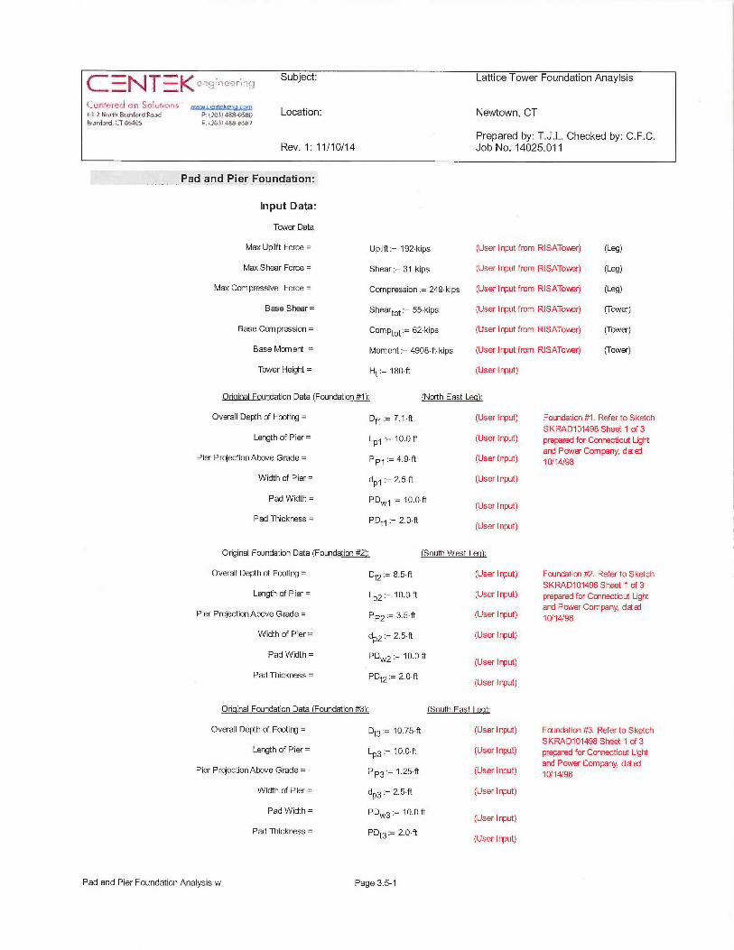
=I~1~~ ~zfi~q~l9~?fill~~ i -
'~f'~it~FtL (~ r~.il JP_~~i~11{Yry3 5~1e~i-; H'uri~i &,uifai,l Ft~xl €~: ~. Y'~i~.!l~3i :4ii
19ani~ied. ~_T sr~iiiy F..X+6i sL'~-K_-N"r
Tower Foundation Anaylsis
Location: Newtown, CT
Prepared by: T.J.L. Checked by: C.F.C.Rev. 1: 11/10/14 Job No. 14025.011
__ __ ___ Pad and Pier Foundation:
Input Data:
Tower Data
Max Uplift Force = Uplift:= 192 kips
Max Shear Force = Shear = 31-kips
Max Compressive Force = Compression = 249 kips
Base Shear= Sheartot - 55 kips
Base Compression = Com 62 ki sPtot P
Base Moment = Moment:= 4908 ft kips
Tower Height = Ht := 180 ft
(User Input from RISATov"er) (Leg)
(User Input from RISATow,er) (Leg)
(User Input from RISATow,er) (Leg)
(Userinputfrom RISATower) (Tower)
(Userinputfrom RISATower) (Tower)
(User I nput from RISATo~ner) (Tower)
(Userinput)
Original Foundation Data (Foundation #11: (North East Leal:
Overall Depth of Footing = Df1 7.1~ft (User Input)
Length of Pier = LPG := 10.0 ft (User Input)
Pier Projection Above Grade = PPS := 4.9 ft (User Input)
Width of Pier= dP~ 2.5 ft (User Input)
Pad Width = pD~,y~ := 10.0 ft (User Input)
Pad Thickness = P~t~ := 2.O ft (User Input)
Original Foundation Data (Foundation #21: (South West Lea):
Overall Depth of Footing = Df2:= 8.5~ft (User Input)
Length of Pier = LPZ - 10.0 ft (User Input)
Pier Projection Above Grade = P 3.5 ft (User Input)P2 ~-
Width of Pier= dP2 2.5 ft (User Input)
Pad Width = PD"~,2 := 10.0 ft (User Input)
Pad Thickness = P~t2:= Z.O~ft (User Input)
Original Foundation Data (Foundation #3): (South East Lea):
Overall Depth of Footing = Df3 10.75~ft (User Input)
Length of Pier = LP3 := 10.0 ft (User Input)
Pier Projection Above Grade = PP3:— 1.25 ft (User Input)
Width of Pier= dP3 - 2.5 ft (User Input)
Pad Width= PD„~,3:=10.Oft (Userinput)
Pad Thickness = P~t3:= 2~~'ft (User Input)
Foundation #1. Refer to Sketch
SKRAD101498 Sheet 1 of 3prepared for Connecticut Lightand Power Company, d~ai
10/14/98
Foundation #2. Refer to SketchSKRAD101498 Sheet 1 of 3prepared for Connecticut Lightand Power Company, d~~
10/14/98
Foundation #3. Refer to SketchSKRAD101498 Sheet 1 of 3prepared for Connecticut Lightand Power Company, d~ai10/ 14/98
Pad and Pier Foundation Analysis w Page 3.5-1
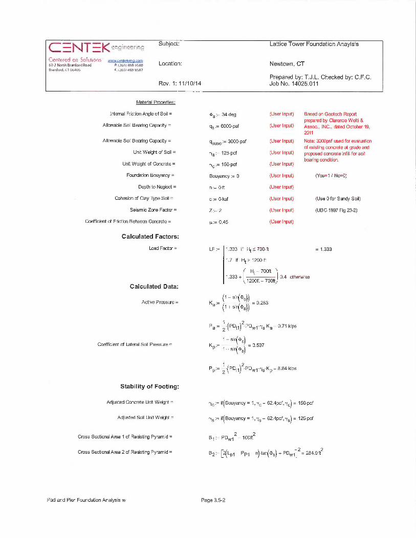
14arr1~d, iT a+~ti~5 c.~~#,b~av51.-8±.~v7
Lattice Tower Foundation Anaylsis
Location: Newtown, CT
Prepared by: T.J.L. Checked by: C.F.C.Rev. 1: 11/10/14 Job No. 14025.011
Material Properties:
Irrternal Friction Angle of Soil =
Allowable Soil Bearing Capacity =
Allowable Soil Bearing Capacity =
Unit Weight of Soil =
Unit Weight of Concrete =
Fourxlation Bouyancy =
Depth to Neglect =
Cohesion of Clay Type Soil =
Seismic Zone Factor =
Coefficient of Friction Between Concrete =
Calculated Factors:
Load Factor =
Calculated Data:
Active Pressure =
Coefficient of Lateral Soil Pressure =
Stability of Footing:
Adjusted Concrete Unit Weight =
Adjusied Soil Unit Weight =
Cross Sectional Area 1 of Ressting Pyramid=
Cross Sectional Area 2 of Ressting Pyramid =
~S := 34 deg (User Input) Based on Geotech Reportprepared by Clarence Welti &
qs:= 6000 psf (User Input) Assoc., INC., dated October 19,2011
gsuse — 3000 psf (User I nput) Note: 3000psf used for evaluationof epsting concrete at grade and
rys := 125 pcf (User I nput) proposed concrete infill fa sdlbearing condition.
-y~-150pcf (Userinput)
Bouyancy:= 0 (User Input) (Yes=1 / No=O)
n :=Oft (User l nput)
c := 0~ ksf (User I nput) (Use 0 for Sandy Soil)
Z 2 (User Input) (UBC-1997 Fig 23-2)
µ:= 0.45 (User input)
LF := 1.333 if Ht _< 700 ft = 1.333
1.7 if Ht >_ 1200 ft
1.333 + ~ 1 OOft ~~7pph)
0.4 otherwise
(1 — sin(~S))K :— ~ 0.283a (1 + sin(~S))
Pa:= 2~(PDt~)2 PDW~~75 Ka= 0.71 kips
1 + sin(~SlKP ~ ~ 3.537
1 —sires)
PP:= Z (PDt~)2~PD~,~~ryS KP= 8.84 kips
rye:= if(Bouyancy = 1,ry~ — 62.4pcf,ry~) = 150 pcf
rys:= if(Bouyancy = 1,rys — 62.4pcf,rys) = 125 pcf
8~:= PDN,~z= 100ft2
BZ:= [2(LP~ —PPS — n) tan(~5) + PDN,~]z= 284.9ft2
Pad and Pier Foundation Analysis w Page 3.5-2
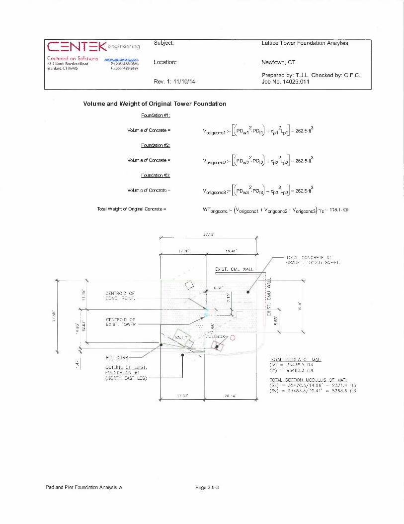
~/ ~+rti ~~,~rir,~~ Subject: Lattice Tower Foundation Anaylsis
'~f'f5fr_f~~ x=11 ~~~~UI~[~1'_:a~-},~~,~,~~,r~~~,~ ~ti~~,#~~,~ Location: Newtown, CTBeanfad.~?[`6..105 F.~~D}otE2it~4~'t
Prepared by: T.J.L. Checked by: C.F.C.Rev. 1: 11/10/14 Job No. 14025.011
Volume and Weight of Original Tower Foundation
Foundation #1:
Volum e aF Concrete = Vorigconc1 ~— [(PD~,~,~2~PDt~) + dP.~ZLP~] = 262.5~ft3
Foundation #2:
Volum e aF Concrete = Vorigconc2 ~— [CPD~,~,22~ PD~2) + dP22LPz] = 262.5•ft3
Foundation #K3:
Volum e of Concrete = Vorigconc3 ~— [(PD,~,~32• PDt3) + dP3ZLP3] = 262.S~ft3
Total Weight of Original Concrete = WTorigconc ~— ~Vorigconc1 + Vorigconc2+ Vorigconc3~'"Yc - 118.1 kip
37.18'
CENTROID OFCONC. REWF.
N GENTROID OF~o ro EXIST. TOWERa N
BIT. CURB ~r~ OUTLWE OF EXIST.
FOUNDATION #1(NORTH EAST LEGI
17.76' 19.41'
TOTAL CONCRETE ATGRADE = 812.6 SQ—FT.
EXIST. CMU WALL
J... ...
Q0.31.. ~/~
~f ~N U
~ ~~ m
D I'XW_ ro
VAULT ~ ~ PUL BOX
TOTAL INERTIA OF MAT:(Ix) = 35476.3 ft4(IY) = 93483.3 ft4
TOTAL SECTION MODULUS OF MAT:(Sx) = 35476.3/14.96' = 2371.4 ft3(Sy) = 93483.3/19.41' = 5263.6 ft3
17.03' 20.14'
Pad and Pier Foundation Analysis w Page 3.5-3
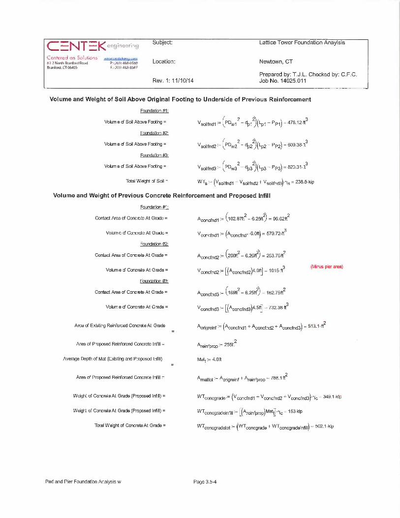
Crn!~-rcr~ do ~c~f~.~l~ctir,s ~-yrra,~.,,.,~a.~.b3-}Har[9i &anfa~d Ra,sd P: yYi11 ~468{si81Y[4aniad.i?Q5A[~5 F.~.i6Si~d;y-jS~7
Subject:
Location: Newtown, CT
Prepared by: T.J.L. Checked by: C.F.C.Rev. 1: 11/10/14 Job No. 14025.011
ower Foundation Anaylsis
Volume and Weight of Soil Above Original Footing to Underside of Previous Reinforcement
Foundation #1:
Volum e cf Shc Abwe Footing = USoilfnd1 - CPD~,~,~ 2 — dP~2)(LP~ — PP.~) = 478.12~ft3
Foundation #2:
Volum e aF Sal Above Footing = usoilfnd2 ~- (PDw22 — dPZZ)(LPZ — PPZ) = 609.38•ft3
Foundation #3:
Volum e cF Sal Above Footing = usoilfnd3 =- (P~w3Z— dp3z)~~p3 — PP3~ - 820•3~'ft3
Total Weight of Soil = WTs ~— ~Usoilf~d1 +Usoilfid2+usoilfnd3~'7s - 238.5~kip
Volume and Weight of Previous Concrete Reinforcement and Proposed Infill
Foundation #1:
Contact Area of Conc~e~At Grade = Aconcfnd1 ~- \~02.87ft2— 6.25ftZ) = 96.62ft2
Volume cf Concrete At Grade = Uconcfid1 ~ ~Aconcfnd1'6.Oft) = 579.72~ft3
Foundation #2:
Contact Area of Concrete At Grade = Aco~cfnd2 ~— 1260ft2 — 6.25ftZ) = 253.75ft2
Volum e cf Concrete At Grade = V •— [(A )4.Oft] = 1015•ft3 (Minus pier area)
concfnd2 ~ concfnd2
Foundation #3:
Contact Area of Conc Sete At Grade = Aconcfnd3 ~— ~169ft2 — 6.25ft2) = 162.75ft2
Volum e d Concrete At Grade = Vconcfnd3 ~— ~~'°`concfid3~4.5ft] = 732.38~ft3
Area of E~osting Reinforoed ConcreteAt Grade Aorigreinf ~— ~Aconcfnd1 + Aconcfnd2 + Aconcfnd3~ — 513.1 ~ft2
Area of Proposed Reinforced Concrete Infill = Areinfprop ~— 255ft2
Average Depth of Mat (E~asting and Proposed InFiII) Matt:= 4.Oft
Area of Proposed Reinforced Concrete Infill = Amattot ~—'4origreinf + Areinfprop - X68.1 ft2
Weight of Concrete At Grade (Proposed Infill) = WTconcgrade ~- ~uconcfnd1 + uconcfnd2 + Vconcfnd3~'7c - 349.1 kip
Weight of Concrete At Grade (Proposed Infill) = WTconcgradeinfill — ~~Areinfprop~Matt]•ry~ = 153~kip
Total Weight of Concrete At Grade = WTco~cgradetot ~- ~WTconcgrade + WTconcgradeinfill~ — 502.1 kip
Pad and Pier Foundation Analysis w Page 3.5-4
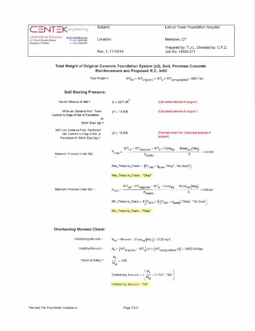
Subject: Lattice Tower Foundation Anaylsis
~a r r;~,~«~ &.~~r~~a~~ s~ ,;~b~~;a~a Location: Newtown, CT~f.1R~d1i~. LT 4ri4~S F,~~ll lif~t~LSy~ll~
Prepared by: T.J.L. Checked by: C.F.C.Rev. 1: 11/10/14 Job No. 14025.011
Total Weight of Original Concrete Foundation System (x3), Soil, Previous ConcreteReinforcement and Proposed R.C. Infill
Total Weight = WTtot - WTorigconc+ WTS+ WTconcgradetot- $58.7~kip
Soil Bearing Pressure:
Section Modulus of Mat = S := 2274.5ft3 (Calculated e~Qernal of program)
Minimum Distance From Tower y1 := 14.62ft (Calculated e~Qernal of program)Centroid to Edge of Mat at Foundation
#1(North East leg) _
Minimum Distance From ReinforcedMat Centroid to Edge of Mat at YZ := 16.83ft (Shortest Lever Arm Calcul ~ ej e#errral cf
Foundation #1 (North East leg) = program)
WTtot - WTorigconc - WTS + Comptot Sheartot (Matt)
Ma~dm um Pressure Under Mat Pm~ Amattot + S - 0.83 ksf
Max_Pressure_Check if(Pmax~gsuse~~~Okay","No Good")
Max Pressure_Check= "Okay"
WTtot - WTorigconc - WTS + Comptot SheartoY~Matt)Minimum Pressure Under Mat = Pmin ~- - = 0.64~ksf
Amattot S
Min_Pressure_Check:= ii[(Pmin'- ~~ ~Pmin ~ gsuse~~~~Okay" , "No Good"]
Min_Pressure_Check= "Okay"
Overturning Moment Check:
Overturning Moment =
Resisting Momerrt =
Factor of Safety =
Mot := Moment + Sheartot Matt) = 5128 kip ft
Mr' ~WTorigconc + WTS)~y1 + (WTconcgradetot'y2) - 13663.3ft kips
~r= 2.66
Mot
M~Overturning_Moment = i > 2, "OK" , "NG"
Mot
Overturning_Moment = "OK"
Pad and Pier Foundation Analysis w Page 3.5-5
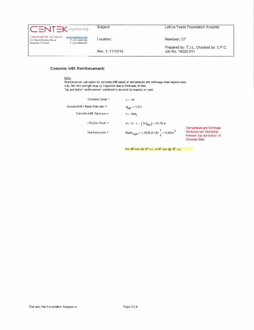
1~ T Subject: Lattice Tower
~i.nr~recl ~n ~_ ~~i~<7~=_.~,,-?H~,~,~,~~,~~ p:,,~},~,~~;~,; Location: Newtown, CTF~animd,tTU~iGS [:~.~fitis~t~'i
Prepared by: T.J.L. Checked by: C.F.C.Rev. 1: 11/10/14 Job No. 14025.011
Concrete Infill Reinforcement:
Note:
Reinforcement calculation for concrete infill based on temperature and shrinkage steel requirementsonly. Moment strength okai by inspection due to thickress of slab.Top and bottom reinforcement combined to account for required amount
Concrete Cover = c := 3in
Assumed Min Rebar Diameter = dbar 0.5in
Concrete I nfill Thickness = h := Matt
Effective Depth = d := h — c — (.5~ dbar~ — 44.75 in
Reinforcement = Reinfregd ̀ ~~0018 d 1 ft) 1 = 0.48 inZ2
Use #16 bars @ 10" o. c. or #7 bars @ 12" o.c.
(temperature and Shrinkage
Reinfacemerrt DistributedBetween Top and Bottom ofConcrete Slab)
Pad and Pier Foundation Analysis w Page 3.5-6
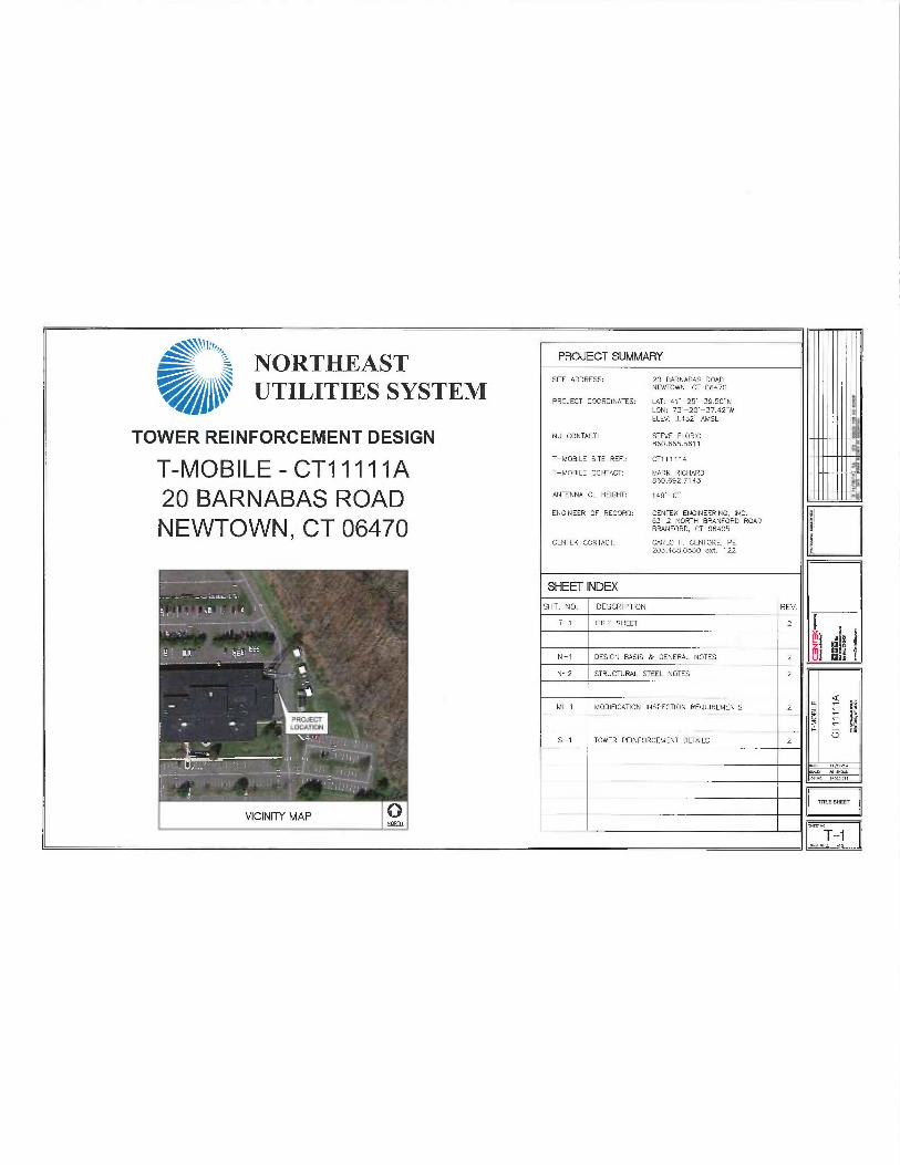
~\\'I'/~~03 PROJECT SUMMARYNORTHEAST~~~ UTILITIES SYSTEM
S~TE ADDRESS Zo eARNABAs ROAD/'I~ NEV✓TOWN, CT 06470
PROJECT COORDINATES: LAT: 41'-25'-39.50"NLON: 73'-20"-37A7'WELEV: 1452' AMSL
TOWER REINFORCEMENT DESIGN N~ ~°NT^~T: ST~,E F~°R'°860.665.5611
T—MOBILE — CT11111 A T—MOB'~E S~TE REF.: ~T,,,,,AT—MOBILE CONTACT: MARK RICHARD
860.692.7143
20 BARNABAS ROAD ""TE""" ~~ "E'~"T ,49'—°"ENGINEER OF RECORD: CENTEK ENGINEERING, INC.
NEWTOWN, CT 06470 fi3-2 NORTH BRANFORD ROAD9RANFORq CT 06405
CENTEK CONTACT: CARLO F. CENTORE, PE203.488.0580 ext. 122
SHEET INDEX
SHT. N0. DESCRIPTION REV.
T-1 TITLE SHEET 2
N-1 DESIGN OASIS & GENERAL NOTES Z
N-2 STRUCTURAL STEEL NOTES 2
MI-1 MODIFlCATION INSPECTION REQUIREMENTS 2
~ 5-1 TOWER REW FORCEMENT DETAILS 2
IIIIIIIII~IIIIIIIII@IIIIIIIIIo~
-.-
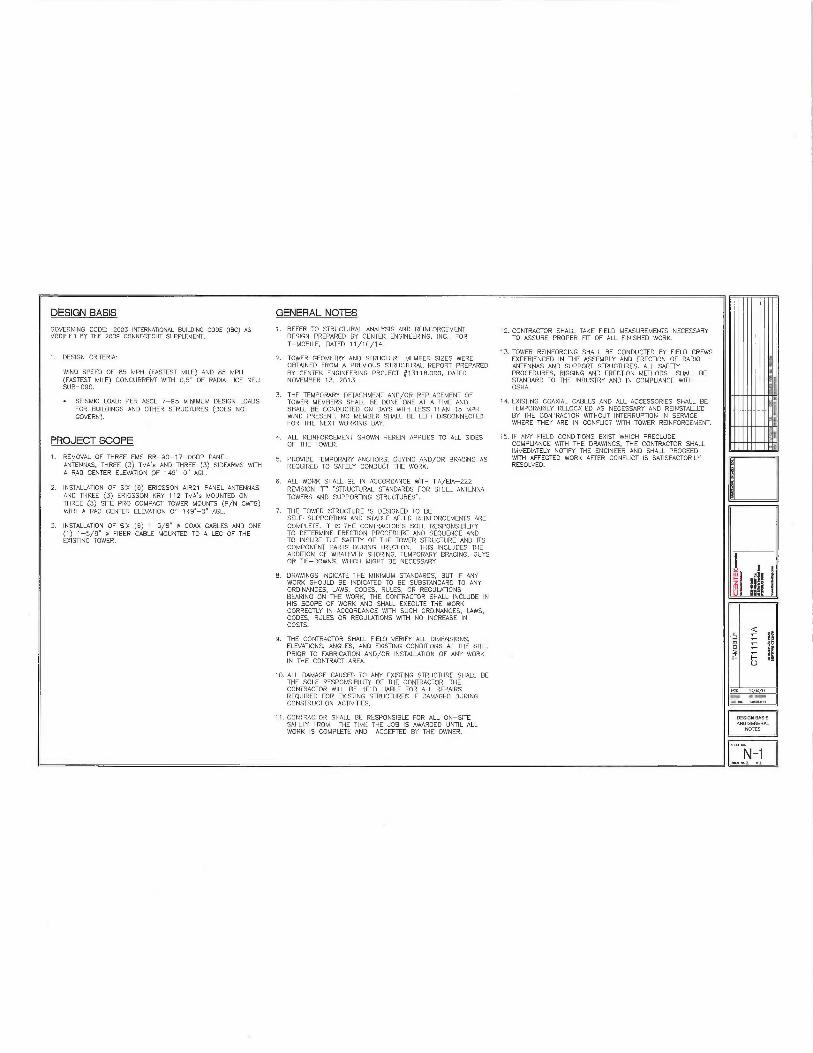
DESIGN BASIS GENERAL NOTES
GOVERNING CODE: 2003 IMERNATIONAL BUILDING CODE (IBC} AS 1. REFER TO STRUCTURAL ANALYSIS ANO REWFORCEM ENT 12. CONTRACTOR SHALL TAKE FIELD MEASUREMEMS NECESSARYMO~IFlE~ BY THE 2009 CONNECTICIfT SUPPLEMENT. DESIGN PREPARED 8Y CENTEK ENGINEERING, INC., FOR TO ASSURE PROPER FIT OF ALL FINISHED WORK.
T—MOBILE, DATED 1 1/10/14.13. TOWER REINFORCING SHALL BE CONDUCTED BY FIELD CREWS
1. DESIGN CRITERIA: 2. TOWER GEDMEfRY ANO STRUCTURE MEMBER SIZES WERE EXPERIENCED IN THE ASSEMBLY AND ERECTION OF RADIOOBTAINED FROM A PREVIOUS STRUCTURAL REPORT PREPARED ANTENNAS AND SUPPORT STRUCTURES. ALL SAFEfY
WIND SPEED OF 85 MPH (FASTEST MILE) AND 85 MPH BY CENTEK ENGINEERING PROJECT #13718.000, DATED PROCEDURES, RIGGING AND ERECTION MEfH00S SHALL BE(FASTEST MILE) CONCURRENT WITH 0.5'~ OF RADIAL ICE NEU NOVEMBER 13, 2013. STANDARD TO THE INDUSTRY AND IN COMPLIANCE WfTHSUB-090. OSHA.
3. THE TEMPORARY DETACHMENT AND/OR REPLACEMENT OF• SEISMIC LOAD: PER ASCE 7-95 MINIMUM DESIGN LOADS TOWER MEMBERS SHALL BE BONE ONE AT A TIME AND 14. EXISTING COAXIAL CABLES AND ALL ACCESSORIES SHALL BE
FOR BUILDINGS. ANA 07HER STRUCTURES (DOES NOT SHALL BE CONDUCTED ON SAYS WITH LE55 THAN 15 MPH TEMPORARILY RELOCATED AS NECESSARY AND REINSTALLEDGOVERN). WIND PRESENT. NO MEMBER SHALL BE LEFT DISCONNECTED BY THE CONTRACTOR WITHOUT INTERRUPTION IN SERVICE
FOR THE NEXT WORKING DAY. WHERE THEY ARE IN CONFLICT WITH TOWER REW FORCEMENT.
PROJECT SCOPE 4- ALL REINFORCEMENT SHOWN HEREIN APPl1ES TO ALL SIDES 15. IF ANY FIELD CONDITIONS EXIST WHICH PRECLUDEOF THE TOWER. COMPLIANCE WITH THE DRAWINGS, THE CONTRACTOR SHALL
IMMEDIATELY NOTIFY THE ENGINEER AND SHALL PROCEED1. REMOVAL OF THREE EMS RR-90-17—OODP PANEL 5. PROVIDE TEMPORARY ANCHORS, GUYING AND/OR 9R4CING AS WITH AFFECTED WORK AFTER CONFLJCT IS SATISFACTORILY
ANTENNAS, THREE (3) TMA~s AND THREE (3) SIDE4RM5 WITH REQUIRED TO SAFELY CONDUCT THE WORK. RESOLVED.A RAC CENTER ELEVATION OF 149'-0" AGL.
6. ALL WORK SHALL BE IN ACCORDANCE WITH TIA/ETA-2222. INSTALLATION ~F SIX (6) ERICSSON AIR21 PANEL ANTENNAS REVISION °F" "STRUCTURAL STANDARDS FOR STEEL ANTENNA
AND THREE (3) ERICSSON KRY 112 TMA's MOUNTED ON TOWERS AND SUPPORi1NG STRUCTURES".THREE (3).SITE PRO COMPACT TOWER MOUNTS (P/N CWiB)WITH A RAD CEMER ELEVATION OF 149'-0" AGL. 7. THE TOWER STRUCTURE IS DESIGNED TO BE
SELF—SUPPORTING AND STABLE AFTER REWFORCEMENTS ARE3. INSTALLA710N OF SIk (6) 1-5/8" m COAX CABLES AN❑ ONE COMPLETE. IT IS THE CONTRACTOR'S SOLE RESPONSIBILIN
(i) 1-5/B" A FIBER CABLE MOUNTED TO A LEG OF THE TO ~ETERMWE EREC710N PROCEDURE ANA SEQUENCE ANDEXISTING TOWER. TO INSURE THE SAFETY OF THE TOWER STRUC7l1RE AND RS
COMPONENT PARTS DURING ERECTION. THIS INCLUDES THEA~~ITION OF WHATEVER SHORMG, TEMPORARY BRACING, GUYSOR TIE—DOWNS, WHICH MIGNT BE NECESSARY.
8. DRAWINGS INDICATE THE MINIMUM STANDARDS, BUT IF ANYWORK SHOULD BE INDICATED TO BE SUBSTANDARD TO ANYORDINANCES, LAWS, CODES, RULES, OR REGt1L4TION5BEARING ON THE WORK, THE CONTRACTOR SHALL INCLUDE INHIS SCOPE OF WORK AND SHALL EXECIfTE THE WORKCORRECTLY IN ACCORDANCE WITH SUCH ORDINANCES, LAWS,CODES, RULES OR REGt1LATIONS WITH NO INCREASE INCOSTS.
9. THE CONTRACTOR SHALL FIELD VERIFY ALL DIMENSIONS,ELEVATIONS, ANGLES, AND EXISTING CONDffIONS AT THE SITE,PRIOR. TO FABRICATION AND/OR INSTALL4TION OF ANY WORKIN THE CONTRACT AREA.
10. ALL DAMAGE CAUSED TO ANY EXISTING STRUCTURE SHALL BETHE SOLE RESPONSIBILITY OF THE CONTRACTOR. THECONTRACTOR WILL BE HELD LIABLE FOR ALL REPAIRSREQUIRED FOR EXISTING STRUCTURES IF DAMAGED DURINGCONSTRUCTION ACTIVITIES.
71. CONTRACTOR SHALL BE RESPONSIBLE FOR ALL ON—SITESAFETY FROM THE TIME THE JOB IS AWARDED UNTIL ALLWORK IS COMPLETE AND ACCEPTED BY THE OWNER.
'I'llll'I~~
"'I'llll~~
IIIIIIIII~~nmm~o~
I-
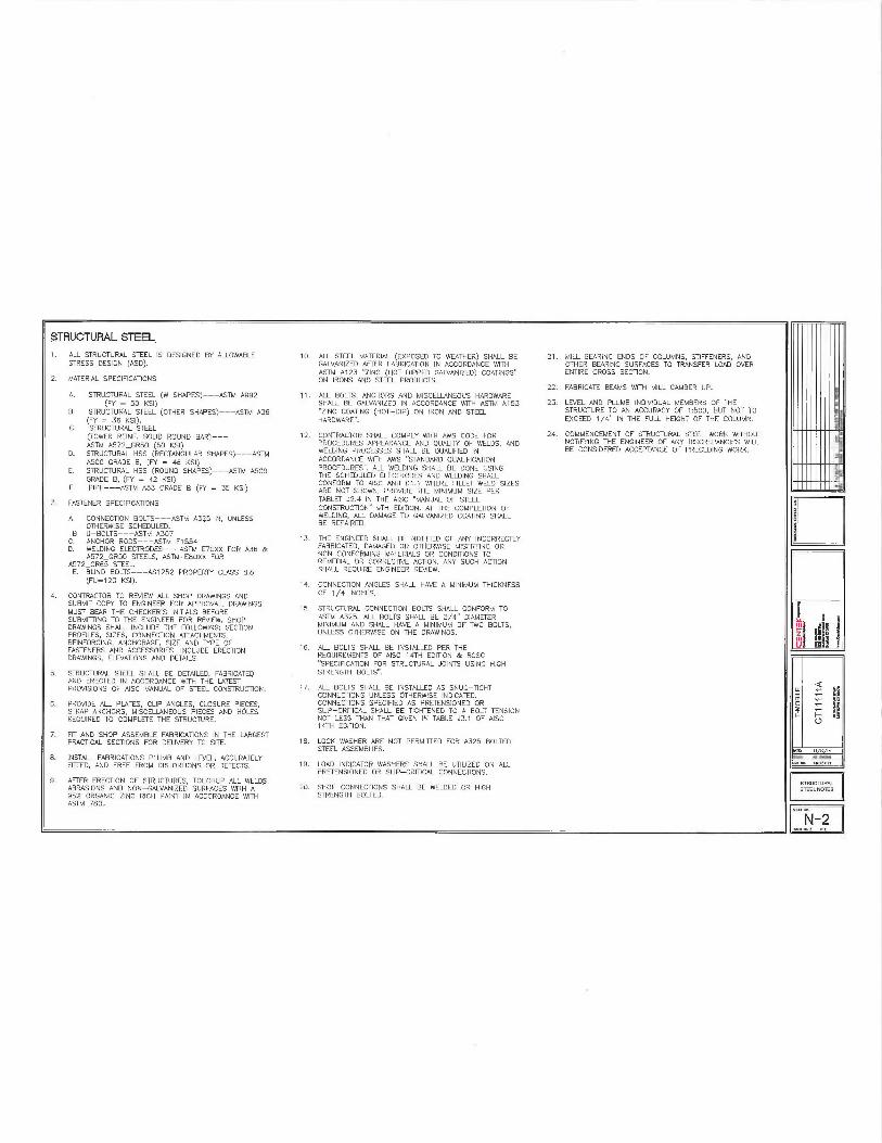
STRUCTURAL STEEL
1. ALL STRUCTURAL STEEL IS ❑ESIGNED BY ALLOWABLESTRESS DESIGN (ASD).
2. MATERIAL SPECIFICATIONS
A. STRUCTURAL STEEL (W SHAPES)---ASTM A992(FY = 50 KSI)
8. STRUCTURAL STEEL (OTHER SHAPES)---ASTM A3fi(FY = 36 KSI).
C. STRUCTUR4L STEEL(TOWER REINF. SOLID ROUND BAR)---ASTM A572_GR50 (50 KSI)
D. STRUCTURAL HSS (RECTANGLIL4R SHAPES)--ASTMA500 GRADE B, (FY = 46 KSI}
E. STRUCTURAL HSS (ROt1N~ SHAPES)--ASTM A500GRADE B, (FY = 42 KSI)
F. PIPE---ASTM A53 GRADE B (FY = 35 K51)
3. FASTENER SPECIFICATIONS
A. CONNECTION BOLTS--ASTM A325-N, UNLESSOlNERWISE SCHEDULED.
B U-BOLTS---ASTM A307G. ANCHOR RODS---ASTM F1554D. WELDING ELECTRODES---ASTM E70XX FOR A36 &
A572_GR50 STEELS, ASTM~E80XX FORA572_GR65 STEEL.E. BLIND BOLTS---AS7252 PROPERN CLASS 8.8
(FU=120 KSI).
4. CONTRACTOR TO REVIEW ALL SHOP DRAWINGS ANDSUBMIT COPY TO ENGINEER FOR APPROVAL DRAWINGSMUST BEAR THE CHECKERS INITIALS BEFORESUBMITTING TO THE ENGINEER FOR REVIEW. SHOPDRAWINGS SHALL INCLUDE THE FOLLOWING: SECTIONPROFILES, SIZES, CONNECTION ATTACHMENTS,REINFORCING, ANCHORAGE, SIZE AND TYPE OFFASTENERS ANO ACCESSORIES. INCLUDE ERECTIONDRAWINGS, ELEVATIaNS AND DETAILS.
5. STRUCTURAL STEEL SHALL BE DETAILED, FABRICATEDAND ERECTED IN ACCORDANCE WITH THE LATESTPROVISIONS OF AISC MANUAL OF STEEL CONSTRUCTION.
6. PROVIDE ALL PLATES, CUP ANGLES, CLOSURE PIECES,STRAP ANCHORS, MISCELLANEOUS PIECES AND HOLESREQUIRED TO COMPLETE THE STRUCTURE.
7. FIT AND SHOP ASSEM6LE FABRICATIONS IN THE L4RGESTPRACTICAL SECTIONS FOR DELIVERY TO SITE.
8. INSTALL FABRICATIONS PLUMB AND LEVEL, ACCURATELYRTTED, AND FREE FROM DISTORTIONS OR DEFECTS.
9. AFTER ERECTION OF STRUCTURES, TOl1CHUP ALL WELDS,ABRASIONS AND NON-GALVAN2ED SURFACES WITH A957 ORGANIC ZINC RICH PAINT IN ACCORDANCE WITHASTM 780.
10. ALL STEEL MATERIAL (EXPOSED TO WEATHER) SHALL BEGALVANIZED AP7ER FABRICATION IN ACCORDANCE WITHASTM A123 "ZINC (HOT DIPPE6 GALVAN2ED) COATMGS"ON IRONS AND STEEL PRODUCTS.
11. ALL BOLTS, ANCHORS AND MISCELLANEOUS HARDWARESHALL BE GALVANIZED IN ACCORDANCE WITH ASTM A153'ZINC COATING (HOT-DIP) ON IRON AND STEELHARDWARE".
12. CONTRACTOR SHALL COMPLY WITH AWS CODE FORPROCEDURES APPEARANCE AND QUALITY OF WELDS, ANDWELDING PROCESSES SHALL BE QUALIFlE~ INACCORDANCE WITH AWS "STANDARD QUALIRCA710NPROCEDURES'. ALL WELDING SHALL BE DONE USINGTHE SCHEDULED ELECTRODES AND WELDING SHALLCONFORM TO AISC AND Di.t WHERE FILLET WELD SIZESARE NOT SHOWN, PROVIDE THE MINIMUM SIZE PERTABLET J2,4 IN THE AISC °MANUAL OF STEELCONSTRUCTION" 9TH EDITION. AT THE COMPLETION OFWELDING, ALL DAMAGE TO GALVANIZED COATING SHALLBE REPAIRED.
13. THE ENGINEER SHALL BE NOTIFlED OF ANY INCORRECTLYFABRICATED, DAMAGED OR OTHERWISE MISFITTING ORNON CONFORMING MATERIALS OR CONDITIONS TOREMEDIAL OR CORRECTNE ACTION. ANY SUCH ACTIONSHALL REQUIRE ENGINEER REVIEW.
14. CONNECTION ANGLES SHALL HAVE A MINIMUM THICKNESSOF 1/4 INCHES.
15. STRUCTURAL CONNECTION BOLTS SHALL CONFORM TOASTM A325.. ALL BOLTS SHALL BE 3/4'~ DIAMETERMINIMUM AND SHALL HAVE A MINIMUM OF N✓0 BOLTS,UNLE53 OTHERWISE ON THE DRAWINGS.
16. ALL 60LTS SHALL BE MSTALLED PER THEREgL11REMENTS OF AISC 14TH EDITION & RCSC"SPECIFICATION FOR STRUCTURAL JOINTS USING HIGHSTRENGTH BOLTS".
17. ALL BOLTS SHALL BE INSTALLED AS SNUG-TIGHTCONNECTIONS UNLESS OTHERWISE INDICATED.CONNECTIONS SPECIFIED AS PRETENSIONED ORSLIP-CRITICAL SHALL BE T{GHTENED TO A BOLT TENSIONNOT LESS THAN THAT GNEN IN TABLE J3.1 OF AISC14TH EDITION.
1B. LOCK WASHER ARE NOT PERMITTED FOR A325 BOLTEDSTEEL ASSEMBl1 E5.
19. LOAD INDICATOR WASHERS SHALL BE UTWZED ON ALLPRETENSIONE~ OR SLIP-CRITICALCONNECTIONS.
20. SHOP CONNECTIONS SHALL BE WELDED OR HIGHSTRENGTH BOLTED_
21. MILL 0E4RING ENDS OF COLUMNS, STIFFENERS, ANDOTHER BEARING SURFACES TO TRANSFER LOAD OVEREMIRE CROSS SECTION.
22. FABRICATE BEAMS WITH MILL CAMBER UP.
23 LEVEL AND PLUMB INDIVIDUAL MEMBERS DF THESTRUCTURE TO AN ACCURACY OF 1:500, BUi NOT TOEXCEED 1/4" IN THE FULL HEIGHT OF THE COLUMN.
24. COMMENCEMENT OF STRUCTUR4L STEEL WORK WITHOUTNOTIFYING THE ENGINEER OF ANY DISCREPANCIES WILLBE CONSIDERED ACCEPTANCE OF PRECEDING WORK.
'llll'll'~~
IIIIIIII1~~
IIII'llll~~nmm~o~
I-
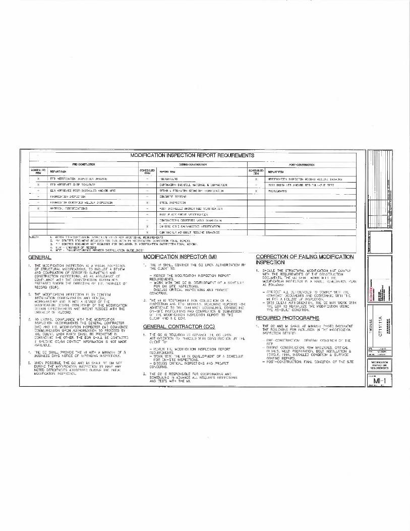
MODIFICATION INSPECTION REPORT REQUIREMENTS
PPECON"ItICTNNJ pUpINO CIX131gUCIqN Pp3i-~N31plIClgN
~~ flH'OR~ I1BA ~~~~ FEPOR~ IIBd ~V'~ PEF1~R~ RBA
X FOR MOD7FICHTIDN INSPECTION ➢RAWING - FOtIN➢ATi~NS X MD➢IFICgTION INSPECTOR RECOR➢ REDLINE ➢RnWINGX FOR APPR~VEO SHIP ➢RAWINGS - EARTHWORK: BACKFILL MATERIAL kCOMPACTION - PAST-INSTALLED ANCHOR RD➢ PULL-BUT TEST- EDR APPROVE➢ PAST-INSTALLE➢ ANCHOR MPII - REHAR A FpRMWORK GEOMETRY VERY ICATION X PHOTOGRAPHS
- FAHRICATIDN INSPECTION - CONCRETE TESTING
- FHHRICATOR CERTIFIE➢ WEL➢ER INSPECTSON X STEEL INSPECTION
X MATERIAL CERTIFICATIONS - POST LJSTALLEU HNCH~R R00 VERIFICgT10N
- HASE PLATE GROt1T VERIFICATION
- CONTRACTOR'S CERTIFIE➢ WEL➢ INSPECTIf1N
X ~N-SITE COL➢ GHLVANRING VERIFICATION
% CONTRACTOR AS-BUILT RELINE ➢RA WINGSNLITFS; 1. REFER TD MODIFICATION INSPECTION NOTES FpR ADDITIONAL RE~UIREMEN TS
2. 'X' OEN~TES ➢OCt1NENT REQUIRE➢ FOR INCLl1SI0N IN MD➢IFICgTIDN INSPECTION FINAL REPORT.3. =' DENOTES ➢pCUHENT NOT RE~l1IRE➢ FOR INCLUSION IN HD➢IFICATIDN INSPECTION FINAL REPORT,4. FOR - ENGINEER pF RECOR➢4. MPII - 'MANUFACTURER'S PRINTS➢ INSTALLFTIDN GUI➢ELINES'
GENERAL
1. THE MO ~IFICATION WSPECTION IS A VISUAL INSPECTIONOF STRUCTl1RAL MODIFICATIONS, TO INCLUDE A REVIEWAND COM PIL4TION OF SPECIFIED SUBMITTALS ANDCONSTRUCTION MSPECTIONS, AS AN ASSURANCE OFCOMPLJANCE WITH THE CONSTRUCTION DOCUMENTSPREPARED UNDER THE DIRECTION OF THE ENGINEER OFRECORD (EOR).
2. THE MODIFICATION INSPECTION IS TO CONFlRMINSTALL4TION CONFIGURATION AND GENERALWORKMANSHIP AND IS NOT A REVIEW OF THEMODIFICATION DESIGN. OWNERSHIP OF THE MODIFICATIONDESIGN EFFECTIVENESS ANO INTENT RESIDES WITH THEENGINEER OF RECORD.
3. TO ENSURE COMPLIANCE WITH THE MODIFICATIONINSPECTION REgl11REMENTS THE GENERAL COMR4CTOR(GC) AND THE MODIFICATION INSPECTOR (MI) COMMENCECOMMUNICATION UPON AUTHORIZATION TO PROCEED BYTHE CLIENT. EACH PARTY SHALL BE PROACTIVE INCONTACTING THE OTHER. THE FOR SHALL BE CONTACTEDIF SPECIFIC GC/MI CONTACT INFORMATION IS NOT MADEAVAILABLE.
4. THE GC SHALL PROVIDE THE MI WITH A MINIMUM OF 561J51NES5 DAYS NOTICE OF IMPENDING INSPECTIONS.
5. WHEN POSSIBLE, THE GC AND MI SHALL BE ON SITEDURING THE MODIFICATION INSPECTION TO HAVE ANYNOTED DEFICIENCIES ADDRESSED DURING THE INITIALMODIFICATION WSPECTION.
MODIFICATION INSPECTOR (MI)
1. THE MI SHALL CONTACT THE GC UPON AUTHORIZATION BYTHE CLIEIJT TO:
— REVIEW THE MOgIFICATION INSPECTION REPORTREQUIREMEM'S.— WORK WITH THE GC IN DEVELOPMENT OF A SCHEDl1LEFOR ON—SRS INSPECTIONS.
— DISCUSS CRITICAL INSPECTIONS AND PROJECTCONCERNS.
2. THE MI IS RESPONSIBLE FOR COLLECTION QF ALLINSPECTION AND TEST REPORTS, REVIEWING REPORTS FORADHERENCE TO THE CONTRACT DOCUMENTS, CONDl1CTINGON—SITE INSPECTIONS AND COMPIL4TION &SUBMISSIONOF THE MODIFICATION INSPECTION REPORT TO THECLIENT AND THE EOR.
GENERAL CONTRACTOR (GC)
i. THE GC IS REgUIRE~ 70 CONTACT THE GC UPONAUTHORI2AilON TO PROCEED WITH CONSTRUCTION BY THECLJ ENT T0:
— REVIEW THE MODIFICATION WSPECTION REPORTREQUIREMENTS.— WORK WITH THE MI IN DEVELOPMENT OF A SCHEOIJLEFOR ON—SITE INSPECTIONS.
— DISCUSS CRITICAL INSPECTIONS AND PROJECTCONCERNS.
2. THE GC IS RESPONSIBLE FOR COORDINATING ANDSCHEDULING IN ADVANCE ALL RE4UIRE~ INSPECTIONSAND TESTS WITH THE MI.
CORRECTION OF FAILING MODIFICAl10NINSPECTION
1. SH OLIL➢ THE STRUCTURAL MODIFlCATION N4T COMPLYWfiH THE REQUIREMENTS OF THE CONSTRUCTIONDOCUMENTS, THE GC SHALL WORK WITH THEMODIFICATION INSPECTOR IN A VIABLE REME~IATION PL4NAS FOLLOWS:
— CORRECT ALL DEFICIENCIES TO COMPLY WITH THECONTRACT DOCUMENTS AND COORDINATE WITH THEMI FOR A FOLLOW UP INSPECTION.
— WITH CLIENT AUTHORIZATION, THE GC MAY WORK WITHTHE FOR TO REANALYZE THE A~ODI FICATION USINGTHE AS—BUILT CONDITION.
REQUIRED PHOTOGRAPHS
1. THE GC AND MI SHALL AT MINIMUM PHOTO DOCUMENTTHE FOLLOWING FOR INCLUSION IN THE MODIFICATIONINSPECTION REPORT:
— PRE—CONSTRUCTIOM GENERAL CONDITION OF THESITE.
— DURING CONSTRUCTION: RAW MATERIALS, CRITICAL~EfAILS, WELD PREPARATION, BOLT INSTALL4TION &TORQUE, FINAL INSTALLED CONDffION &SURFACECOATING REPAIRS.
— POST—CONSTRUCII.ON: FINAL CONDITION OF THE SITE
IIIIIIIII~~[~
II'llll'I~G~
II'lll"I~~
I-
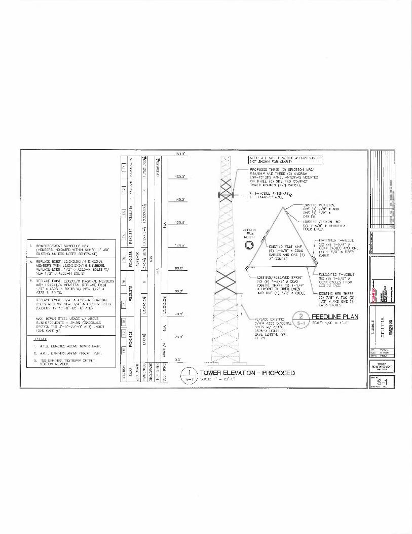
I. REINFORCEMENT SCHEDULE KEY:(MEMBERS INDICATED WffHIN SCHEDULE AREEXISTING UNLESS N07E0 OTHERWISE)
A. REPLACE EXIST. L3.5X3.SX7/4 DIAGONALMEM6ER5 WITH L3.5X3.SX5/16 MEMBERS.REPLACE EKIST. 1/Z" m A325-N 60LTS W/NEW 1/2" 0 A325-N 90LTS.
B. REPLACE EXIST. L2X2X1 /8 DIAGONAL MEMBERSWITH L2X2X1 /4 MEM6ER5. REPL4CE EXIST.1 /2" 0 A325-N BOLTS W/ NEW 1/2" 0A325-N BOLTS.
ftEPL4CE IXIST. 3/4" 0 A325-N DIAGONAL80LT5 WITH W/ NEW 3/4" m A325-X BOLTS(SECTION T7 40'-0'-60'-0" ATB)
MAX. TOWER STEEL USAGE w/ ABOVEREINFORCEMEMS - 84.9% (DIAGONALSSECTION T10 3' 0"-23'-0" ATB) UNDERLOAD CASE #2
LEGEND:
1. A.T.B. DENOTES A60VE TOWER EASE.
2. A.G.L. DENOTES ABOVE GRADE LEVEL.
3. TXX DENOTES TN XTOWER OUTPUTSECTION NUMBER.
t aao'"'~° .'" NOTE: ALL NON T-M081LE APPURTENANCES
~~~~ NOT SHOWN F"OR CLARITY
~ N PROPOSES 11-TREE (3) ERICSSON AIR21a B2A~B4P AND THREE (3) ANDREW
160.0' LNX-65125 PANEL ANTENNAS MOUNTEDON THREE (3) SfTE PRO COMPACT
N TOWER MOUMS (P/N CWI"01).
in _ T-MOBILE ANTENNASa EL 1149'-0" A.G.L.
140.0'
.,~ EXISTING MUNICIPALN h ONE (1J 7/8" 0 AND
~ ONE (1) 1/2" 6x u~i. CABLESa
Q ~2p.p~ EXISTING VERIZON TNO~ z (2) 1-5/B" 0 HYBRIFLEX
APPROX FIBER LWES.n °' TRUE
NORTHa J Q PROPOSED T-MOBLIE
100.0' EXISTING AT&T NINE SIX (6) 1-5/B" m
~ 9 1-5 8" 0 COAX COAX CABLES AND ONE
L 1 / (i) i—e/s" m FieERN ~ ~ ~ ~' //Ij CABLES AND ONE (1) CABLE
u' ~ ~~ `I 3" CON~IUTnX n X~a a n
Q 80.0'z
• EXISTING RESERVED SPRINT '•RELOCATES T-MOBLIE
SIX 6 1-5 8' 0SIX 6 1-5 B" 0 COAX
~)a O GOAX CABLES FROM
;~ CABLES, THREE (3) 1-1/4" LEG TO FACE0 HYBRIFLEX FIBER LINES -
60.0' AND ONE (1) 1/2" 0 CABLE EXISTING NEU THREE
u~ '~' x ~3) 7/B" 0. TWO (2)1O '~? ~~ 1~2" 0 AND ONE (1)
r "~ X EW63 CABLESu~ ~
400 ~~ry ~ 2 FEEDLINE PLANREPLACE EXISTING~ /~~ ~ 3/4°0 A325 DIAGONAL $-1 SCALE 1/4" = 1'-0"
Q BOLTS w/ 3/4"0Z / A325-x BOLTS OF
a x 20.0' ~~/ ~-_ ~~ OFM2gLENGTH, NP.
~ ~~ ~ {
~/~ ~a
o m a ¢ ¢ ~ o
w w ~ ~ ~ ~ 1 TOWER ELEVATION —PROPOSEDw a ¢ o w0 0 ~ $-1 SCALE: 1° = 20'_0„ -
II'I"III~~
IIII'lll'~~
I'lllll"~~umm~o~
1-
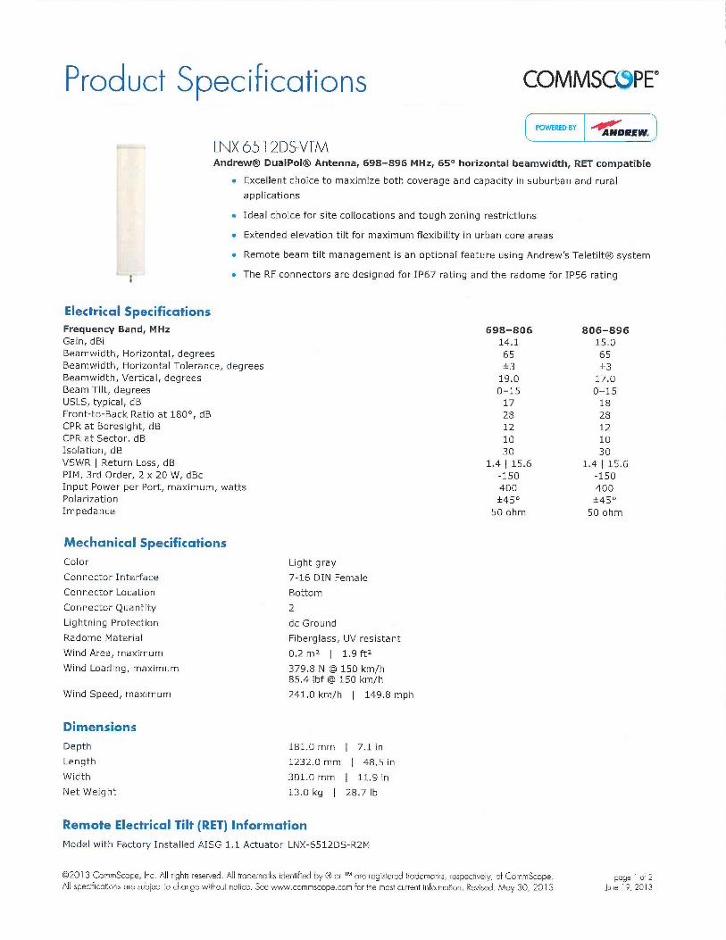
Product S ecificationsp COMMSCC9PE~
POWERED BY DREW
LNX-6512DS-VTMAndrews DualPolO Antenna, 698-896 MHz, 65° horizontal beamwidth, RET compatible
Excellent choice to maximize both coverage and capacity in suburban and rural
applications
. Ideal choice for site collocations and tough zoning restrictions
Extended elevation tilt for maximum flexibility in urban core areas
Remote beam tilt management is an optional feature using Andrew's TeletiltOO system
The RF connectors are designed for IP67 rating and the radome for IP56 rating
Electrical SpecificationsFrequency Band, MHzGain, dBiBeamwidth, Horizontal, degreesBeamwidth, Horizontal Tolerance, degreesBeamwidth, Vertical, degreesBeam Tilt, degreesUSLS, typical, dBFront-to-Back Ratio at 180°, dBCPR at Boresight, dBCPR at Sector, dBIsolation, dBVSWR ~ Return Loss, dBPIM, 3rd Order, Z x ZO W, dBcInput Power per Port, maximum, wattsPolarizationImpedance
Mechanical Specifications
Color
Connector Interface
Connector Location
Connector Quantity
Lightning Protection
Radome Material
Wind Area, maximum
Wind Loading, maximum
Wind Speed, maximum
Dimensions
Light gray
7-16 DIN Female
Bottom
Z
do Ground
Fiberglass, UV resistant
0.2 m2 ~ 1,9 ftz
379.8 N @ 150 km/h85.4 Ibf @ 150 km/h
241.0 km/h ~ 149.8 mph
Depth 181.0 mm ~ 7.1 in
Length 1232.0 mm ~ 48.5 in
Width 301.0 mm ~ 11.9 in
Net Weight 13.0 kg ~ 28.7 Ib
Remote Electrical Tilt (RET) Information
Model with Factory Installed AISG 1.1 Actuator LNX-6512DS-R2M
698-80614.165f319.00-1517281Z1030
1.4 ~ 15.6-150400f45°50 ohm
806-89615.065t3
17.00-151828121030
1.4 ~ 15.6-150400t45°50 ohm
002013 CommScope, Inc. All rights reserved. All trademarks identified by OO or T^^ are registered trademarks, respectively, of CommScope. poge 1 of 2All specifications are subject to change without notice. See www.commscope.com for the most current information. Revised: May 30, 2013 June 19, 2013
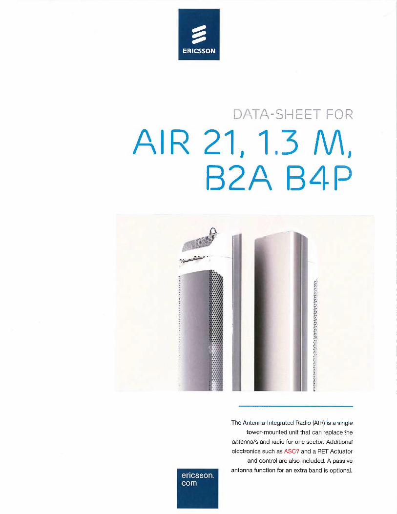
.'~ ~ ~ I~ ~ N
~-_ ~
--
p
" ~~.
~i~
The Antenna-Integrated Radio (AIR) is a single
tower-mounted unit that can replace the
antennas and radio for one sector. Additional
electronics such as ASC? and a RET Actuator
and control are also included. A passive
antenna function for an extra band is optional.
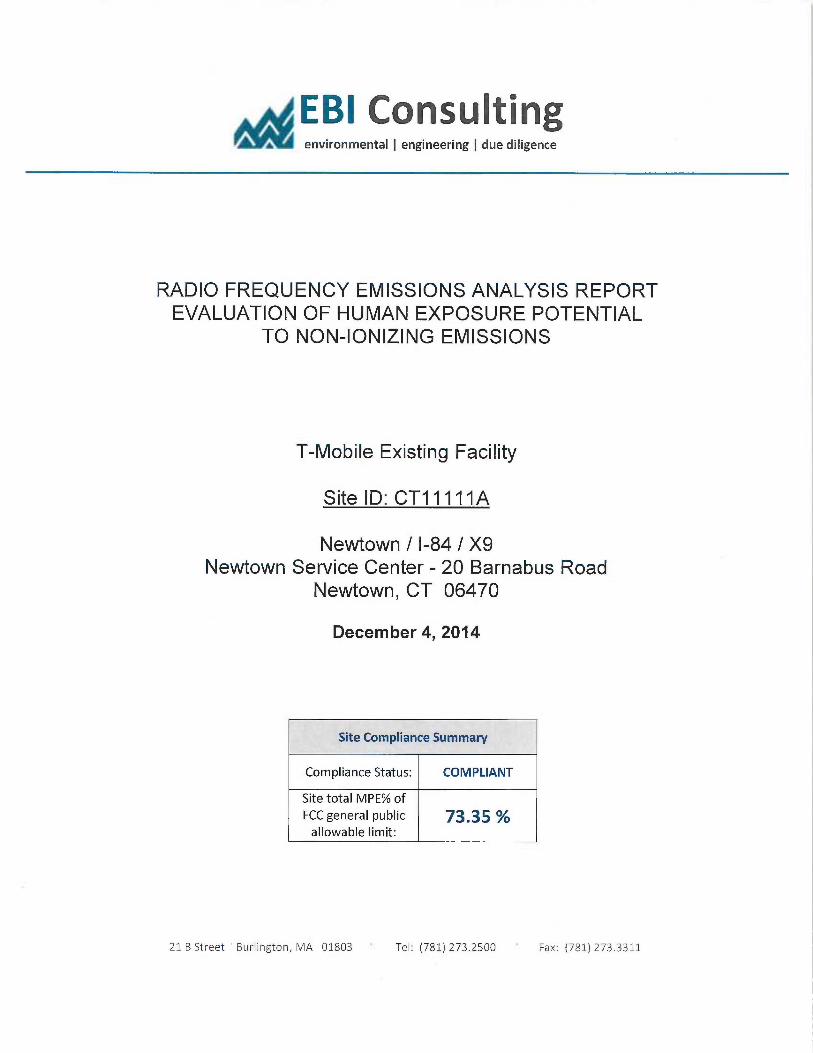
EBI Consulting~ environmental ~ engineering ~ due diligence
RADIO FREQUENCY EMISSIONS ANALYSIS REPORTEVALUATION OF HUMAN EXPOSURE POTENTIAL
TO NON-IONIZING EMISSIONS
T-Mobile Existing Facility
Site ID: CT11111A
Newtown / I-84 / X9Newtown Service Center - 20 Barnabus Road
Newtown, CT 06470
December 4, 2014
Site Compliance Summary
Compliance Status: COMPLIANT
Site total MPE% ofFCC general public ]3.35 Jallowable limit:
21 B Street Burlington, MA 01803 Tel: (781) 273.2500 Fax: (781) 273.3311
EBI Consultingenvironmental ~ engineering ~ due diligence
December 4, 2014
T-Mobile USAAttu: Jason Overbey, RF Manager35 Griffin Road SouthBloomfield, CT 06002
Emissions Analysis for Site: CT11111A —Newtown / I-84 / X9
EBI Consulting was directed to analyze the proposed T-Mobile facility located at Newtown Service
Center - 20 Barnabus Road, Newtown, CT, for the purpose of determining whether the emissions from
the Proposed T-Mobile Antenna Installation located on this property are within specified federal limits.
All information used in this report was analyzed as a percentage of current Maximum Permissible
Exposure (% MPE) as listed in the FCC OET Bulletin 65 Edition 97-01 and ANSUIEEE Std C95.1. The
FCC regulates Maximum Permissible Exposure in units of microwatts per square centimeter (µW/cxn2).
The number of µW/cm2 calculated at each sample point is called the power density. The exposure limit
for power density varies depending upon the frequencies being utilized. Wireless Carriers and Paging
Services use different frequency bands each with different e~osure limits, therefore it is necessary to
report results and limits in terms of percent MI'E rather than power density.
All results were compared to the FCC (Federal Communications Commission) radio frequency exposure
rules, 47 CFR 1.1307(b)(1) — (b)(3), to deternune compliance with the Maximum Pernussible Exposure
(MPE) limits for General Population/Uncontrolled environments as defined below.
General population/uncontrolled exposure limits apply to situations in which the general public maybe
exposed or in which persons who are exposed as a consequence of their employment may not be made
fully aware of the potential for exposure or cannot exercise control over their exposure. Therefore,
members of the general public would always be considered under this category when exposure is not
employment related, for example, in the case of a telecommunications tower that exposes persons in a
nearby residential area.
Public exposure to radio frequencies is regulated and enforced in units of microwatts per square
centimeter (µW/cm2). The general population exposure limit for both the PCS and AWS bands is 1000
µW/cmz. Because each carrier will be using different frequency bands, and each frequency band has
different exposure limits, it is necessary to report percent of MPE rather than power density.
21 B Street 'Burlington, MA 01803 Tef: (781) 273.2500 Fax: (781) 273.3311
E61 Consulting~ environmental ~ engineering ~ due diligence
OccupationaUcontrolled exposure lunits apply to situations in which persons are exposed as aconsequence of their employment and in which those persons who are exposed have been made fullyaware of the potential for exposure and can exercise control over their exposure. OccupationaUcontrolledexposure limits also apply where exposure is of a transient nature as a result of incidental passage througha location where exposure levels maybe above general population/uncontrolled limits (see below), aslong as the exposed person has been made fully aware of the potential for exposure and can exercisecontrol over his or her exposure by leaving the area ar by some other appropriate means.
Additional details can be found in FCC OET 65.
CALCULATIONS
Calculations were done for the proposed T-Mobile Wireless antenna facility located at Newtown ServiceCenter - 20 Barnabus Road, Newtown, CT, using the equipment information listed below. Allcalculations were performed per the specifications under FCC OET 65. Since T-Mobile is proposinghighly focused directional panel antennas, which project most of the emitted energy out toward thehorizon, all calculations were performed assuming a lobe representing the maximum gain of the antennaper the antenna manufactures supplied specifications, minus 10 dB, was focused at the base of the tower.For this report the sample point is the top of a 6 foot person standing at the base of the tower.
For all calculations, all equipment was calculated using the following assumptions:
1) 2 GSM channels (I'CS Band - 1900 MHz) were considered for each sector of the proposed
installation. These Channels have a transmit power of 30 Watts per Channel
2) 2 UMTS channels (AWS Band — 2100 MHz) were considered for each sector of the proposed
installation. These Channels have a transmit power of 30 Watts per Channel.
3) 2 LT`E channels (AWS Band — 2100 MHz) were considered for each sector of the proposedinstallation. These Channels have a transmit power of 60 Watts per Channel.
4) All radios at the proposed installation were considered to be running at full power and were
uncombined in their RF transmissions paths per carrier prescribed configuration. Per FCCOET Bulletin No. 65 -Edition 97-01 recommendations to achieve the maximum anticipatedvalue at each sample point, all power levels emitting from the proposed antenna installationare increased by a factor of 2.56 to account for possible in-phase reflections from thesurrounding environment. This is rarely the case, and if so, is never continuous.
21 B Street 'Burlington, MA 01803 Tel: (781) 273.2500 ~ Fax: (781) 273.3311
EBI Consultingenvironmental ~ engineering ~ due diligence
5) For the following calculations the sample point was the top of a six foot person standing at
the base of the tower. The ma~mum gain of the antenna per the antenna manufactures
supplied specifications minus 10 dB was used in this direction. This value is a very
conservative estimate as gain reductions for these particular antennas are typically much
higher in this direction.
6) The antennas used in this modeling are the Ericsson AIR21 B4A/B2P for 1900 MHz (PCS)
and 2100 MHz (AWS) channels. This is based on feedback from the carrier with regards to
anticipated antenna selection. The Ericsson AII221 B4A/B2P has a maximum gain of 15.9
dBd at its main lobe. The maximum gain of the antenna per the antenna manufactures
supplied specifications, minus 10 dB, was used for all calculations. This value is a very
conservative estimate as gain reductions for these particular antennas are typically much
higher in this direction.
7) The antenna mounting height centerline of the proposed antennas is 149 feet above Bound
level (AGL).
8) Emissions values for additional carriers were taken from the Connecticut Siting Council
active database. Values in this database are provided by the individual carriers themselves.
All calculations were done with respect to uncontrolled /general public threshold limits.
21 B Street "Burlington, MA 01803 Tel: (781) 273.2500 Fax: (781} 273.3311
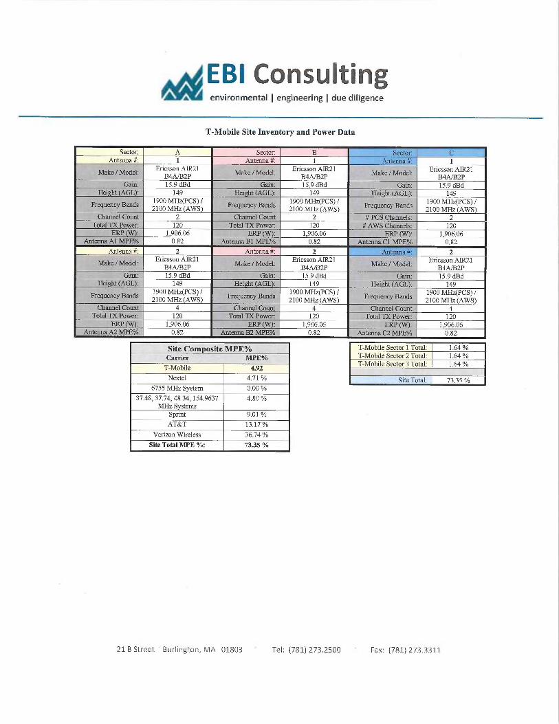
EBI Consulting~ environmental ~ engineering ~ due diligence
T-Mobile Site Inventory and Power Data
Sector: A Sector: B Sector:Antenna #: 1 Antenna #: 1 Antemia #: 1
Ericsson AIIt21 Ericsson AIIt21 Ericsson AII221Make /Model: B4A/B2P
Make /Model_ B4~2P Make /Model. B4A/B2P
Gain: 15.9 dBd Crain: 15.9 dBd Gain: 15.9 dBdHei t AGL : 149 Hei ht AGL): 149 Hei t AGL : 149
Frequency Bands 1900 MHz(PC3) /
Frequency Bands 1900 MHz(PCS) /
Frequency Bands 1900 MHz(PCS) /
2100 MHz (AWS) 2100 MHz AWS) 2100 MHz AWSChannel Cotmt 2 Channel Count 2 # PCS Channels: 2
Total TX Power. 120 Total TX Power. 120 # AWS Channels: 120ERP (V~_ 1 906.06 ERP 1 906.06 ERP (lam: 1,906.06
Antenna Al MPE°10 0.82 Antenna Bl MPE°10 0.82 Antenna Cl MPE% 0.82
Antenna #: 2 Antenna #: 2 Antenna #: 2Ericsson AIR21 Ericsson AIIt21 Ericsson ATR21Make !Model. '
B4A/B2P Mme /Model:
B4A/B2P Make /Model:
B4A/B2PCrain: 15.9 dBd Gain: 15.9 dBd Crain. 15.9 dBd
Hei ht (AGL): 149 Hei t (AGL)_ 149 Height (AGL): 149
Frequency Bands 1900 MHz(PCS) /
Frequency Bands 1900 MHz(PCS) /
Frequency Bands 1900 MfIz(PCS) /
2100 MHz (AWS) 2100 MHz (AWS) 2100 MHz AWS)Channel Count 4 Channel Count 4 Channel Count 4
Total T'X Power: 120 Total TX Power. 120 Total TX Power_ 120ERP (~: 1,906.06 ERP 1,906.06 ERP (VV): 1,906.06
Antenna A2 MPE°/o 0.82 Antenna B2 MPE°lo 0.82 Antenna C2 MPE% 0.82
Site Com osite MPE%Carrier MPE%
T-Mobile 4.92
Nextel 4.71 °/a
6755 MHz Syetem 0.00
37.48, 37.74, 48.34, 154.9637 4.80MHz S stems
Sprint 9.01
AT&T 13.17
Verizon Wireless 36.74
Site Total MPE %: 73.35
T-Mobile Sector 1 Total: 1.64T-Mobile Sector 2 Total: 1.64T-MobIle Sector 3 Total: 1.64
Site Total: 7335
21 B Street 'Burlington, MA 01803 Tel: (781) 273.2500 Fax: (781) 273.3311
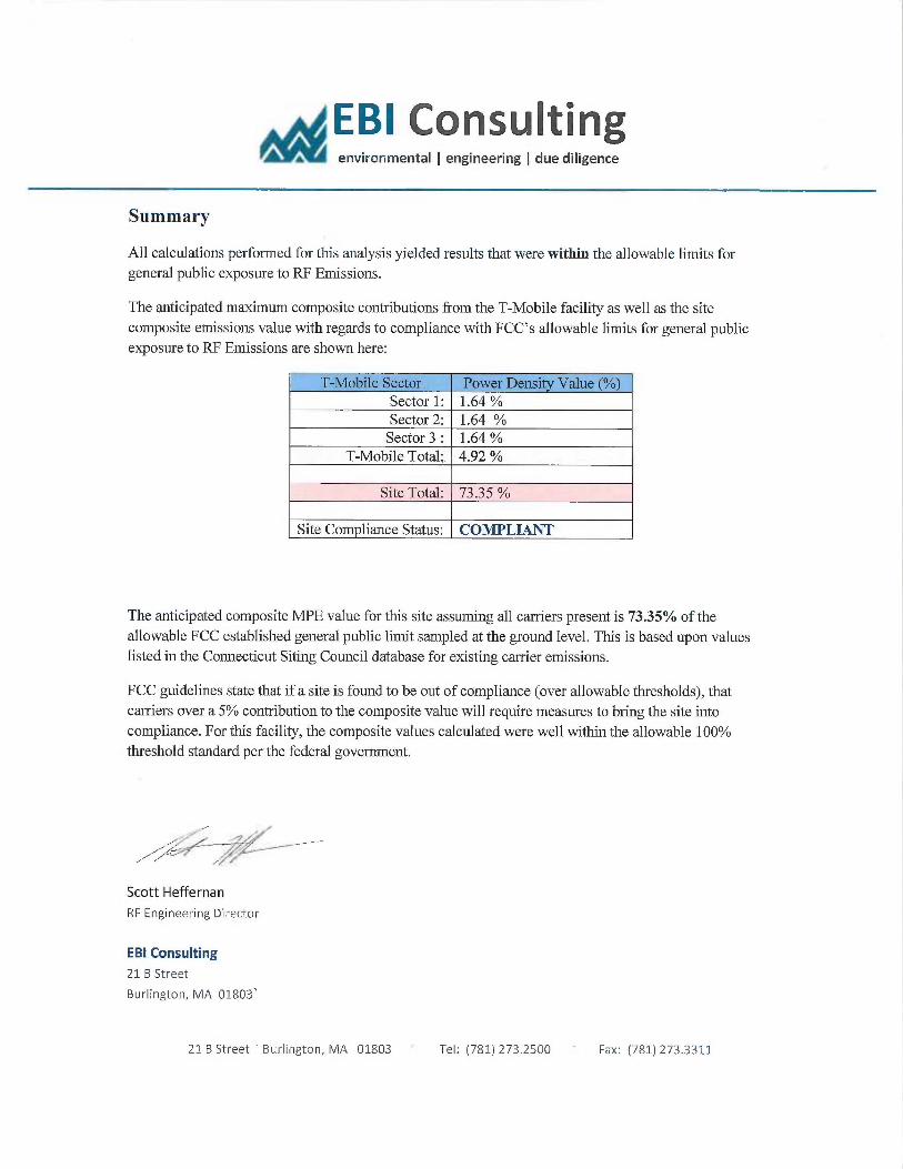
EBI Consultingi, environmental ~ engineering ~ due diligence
Summary
All calculations performed for this analysis yielded results that were within the allowable limits forgeneral public exposure to RF Emissions.
The anticipated maximum composite contributions from the T-Mobile facility as well as the sitecomposite emissions value with regards to compliance with FCC's allowable limits for general publicexposure to RF Emissions are shown here:
T-Mobile Sector Power Densi Value (%)Sector 1: 1.64Sector 2: 1.64Sector 3 : 1.64
T-Mobile Total:. 4.92
Site Total: 73.35
Site Com liance Status: COMPLIANT
The anticipated composite MPE value for this site assuming all carriers present is 73.35% of theallowable FCC established general public limit sampled at the ground level. This is based upon valueslisted in the Connecticut Siting Council database for existing carrier emissions.
FCC guidelines state that if a site is found to be out of compliance (over allowable thresholds), thatcarriers over a 5% contribution to the composite value will require measures to bring the site intocompliance. For this facility, the composite values calculated were well within the allowable 100%threshold standard per the federal government.
f ~ ~ __
Scott Heffernan
RF Engineering Director
EBI Consulting
21 B Street
Burlington, MA 01803
21 B Street Burlington, MA 01803 Tel: (781) 273.2500 Fax: (781) 273.3311
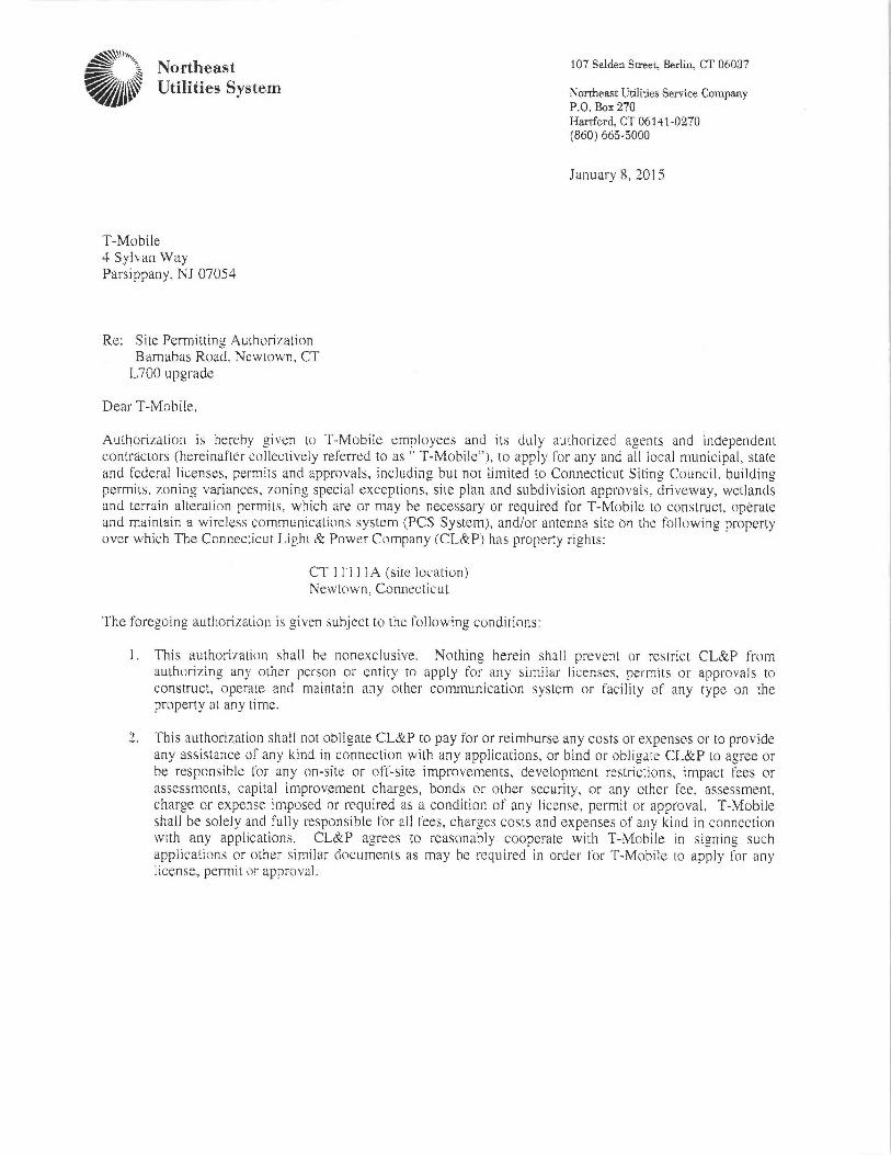
Northeast
~~~~~~~ Utilities System
T-Iviobile4 Sylvan WayParsippany, NJ 07054
Re: Site Permitting AuthorizationBarnabas Raad, Newtown, CTL700 upgrade
Dear T-Mobile,
10? Selden Sweet, Berlin, G'I' 06037
\orrheast Uriliries Sezvice CompanyP,O. Boa 270Hartford, CT 06141-02?0(860)665-5000
January 8, 2015
Authorization is hereby given to T-Mobile employees and its duly authariz~;d agents and independentcc)ntractors (hereina!'ter collectively referred to as " T-Mobile"), to apply Car any and all local municipal, stateand Federal licenses, permits and approvals, including but not limited to Connecticut Siting Council, buildingpermits, zoning variances, -r_oning special exceptions, site plan and subdivision approvals, drire~~ay, wetlandsand terrain alteration permits, which are or may be necessary or required for T-Mobile to construct, operateand maintain a wireless communications system (PCS System), and/or antenna site nn tha following propertyover which The Connecticut Light &Power Company (CL&P) has Property rights:
CT 1 1 1 1 l A (site locati~~n)Neva-town. Connecticut
The foreeoing authorizaCian is given subject to the following conditions:
This authorization shall be nonexclusive. Nothing herein shall prevent or resCrict CL&P fromauthc.~rizing any other person or 4ntity to apply For any similar licenses, permits ar approvals tc~construct, operate and maintain any other communication system or Facility of any type can theproperty at any time.
3. This authorization shall not obligate CL&P to pay for or reimburse. any costs or expenses or to provideany assistance of any kind in connection with any applications, or bind or obligate CL&P to agree orbe responsible for any on-site or otif-site improvements, development restrictions, impact trees orassessments, capital improvement charges, bonds or other security, or any other fe:e, assessment.charge ar expense imposed or required as a condition of any license, permit or appro~raL T-Mobileshall be solely and Yully responsihla for all fees, charges costs and expenses of any kind in connectionwith any applications. CL&P agrees to reasonably cooperate with T-Mobile in signing suchapplications ~r other similar documents as may he required in order for T-Mobile to apply fur anylicense, permit or approval.
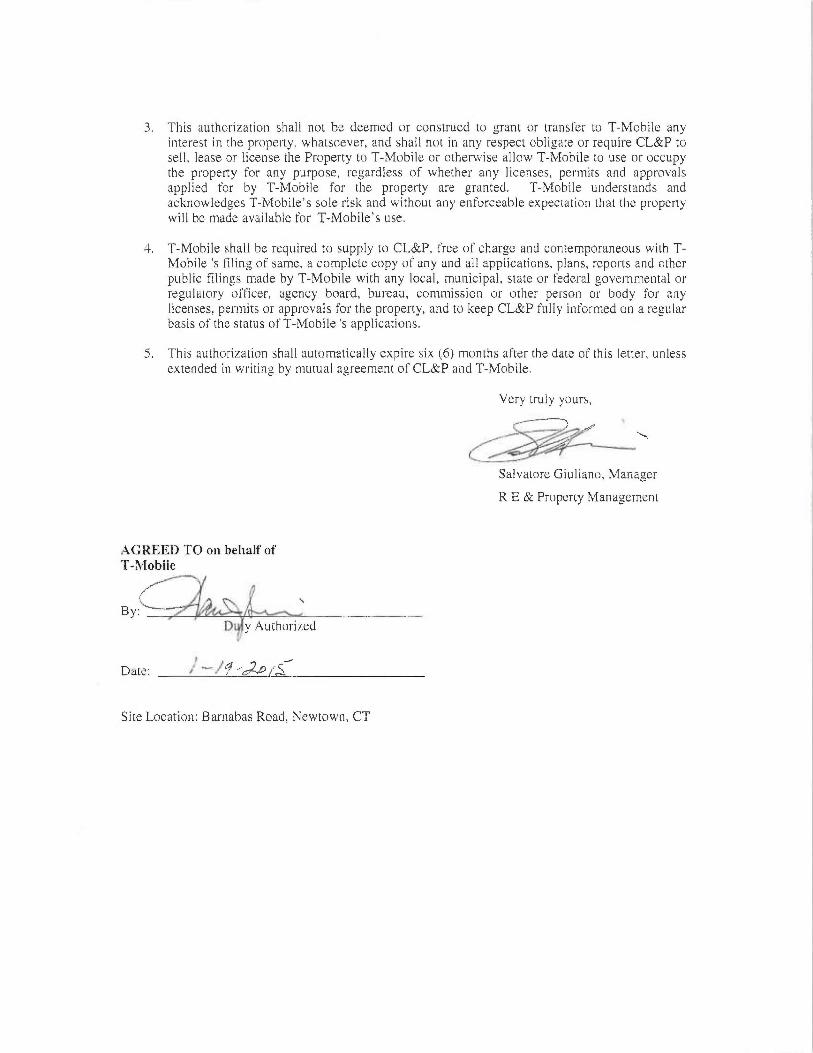
This authorization shall not be deemed «r construed to grant or transfer to T-Mobile anyinterest in the property, whatsoever, and shall not in any respect obligate or require CL&P tosell, lease or License the Property to T-Mobile or otherwise allow T-Mobile to use or occupythe property fir any purpc.~se, regardless cif whether any licenses, permits and apprc~~~alsapplieel ter by T-Mobile for the property are granceci. T-Mobile understands andacknowledges T-Mobile's sale risk and without any enfc~rcealalc; expectatiUn that the propertywill be made availat~le for T-Mabilc's use.
=~. T-Mobile shall Lie r~quircd to supply t~ CI.&F, i'ree oP c;li~rge and contemporaneous with T-Ivlohile 's f'ilin~ of same, a complete copy of any and all a~plicati~ns, plans, reports and etherpublic filings mace by T-Mobila with any local, municipal, state or federal ~~vernmental orre4ulatary ofPice;r, agency heard, bureau, cc~mnussion ar other person or body for anylicenses, permits or approvals liar the property, and to keep CL&P Fully informed on a re~~ularbasis of the status ~f T-Mobile 's applications.
5. This authorization shall autc~maticaIly~ expire six (6) months otter the date of this letter, unlessextended in writing by mutual agreement o 'CLAP and T-Mobile.
Very truly yours,
Salvatore Giuliano, Manager
R E c~u Property Management
AGREED TO on behalf ofT-1~[obile
r~` +1 l
By: r
D y Auth~riredV
Dace: ~' "'~ ~/'~ "cam r°~
5ice Location: Bar~~abas Road, Newtown, CT