gohfn wolf p~
TRANSCRIPT

GOHFNWOLF_P~._ATTORNEYS AT LAW JULIE D. KOHLER
PLEASE REPLY TO: BfICIC~2p01't
WRITER'S DIRECT DIAL: ~ZO3~ 337-4 ~ rJ7
E-Mail Address: [email protected]
September 18, 2014
Attorney Melanie BachmanActing Executive DirectorConnecticut Siting CouncilTen Franklin SquareNew Britain, CT 06051
Re: Notice of Exempt ModificationTown of Stratford/T-Mobile co-locationT-Mobile Site ID CT11872D900 Longbrook Road, Stratford CT
Dear Attorney Bachman:
This office represents T-Mobile Northeast LLC ("T-Mobile") and has been retained tofile exempt modification filings with the Connecticut Siting Council on its behalf.
In this case, the Town of Stratford owns the existing telecommunications tower andrelated facility on the Stratford Police Department building, 900 Longbrook Road, StratfordConnecticut (latitude 41.20177, longitude -73.12885). T-Mobile intends to add three antennasand related equipment at this existing rooftop facility in Stratford ("Stratford Facility"). Pleaseaccept this letter as notification, pursuant to R.C.S.A. § 16-50j-73, of construction whichconstitutes an exempt modification pursuant to R.C.S.A. § 16-50j-72(b)(2). In accordance withR.C.S.A. § 16-50j-73, a copy of this letter is being sent to the Mayor, John A. Harkins. The Cityof Stratford also owns the property.
The existing Stratford Facility consists of a rooftop mounted 50 foot guyed tower andassociated compound area on the top of the Police Department building. T-Mobile plans toadd three antennas and three remote radio units (RRUS) mounted on the rooftop facility at acenterline of 47 feet (79 feet AGL). (See the plans revised to September 15, 2014 attachedhereto as Exhibit A). The existing rooftop facility is structurally capable of supporting T-Mobile's proposed use, as indicated in the structural certification dated September 12, 2014and attached hereto as Exhibit B.
LLLS BROAD STREET iSH DEER HILL AVENUE 32O POST ROAD WEST 6S~ ORANGE CANTER ROAD
P.O. BOX 1H21 DANBURY, CC O6S1O WESTPORT, CT O6HHO ORANGE, CI~ OG477BRIDGEPORT, C'I' 06601-1821 TeL: (203) 7922771 TeL: (203) 222-1034 'ILL: (203) 298 066
Ts[.: (203) 368-0211 Fax: (203) 791-8149 Fnx: (203) 227-1373 Fax: (203) 298068
Fax: (203) 3949901

COH~NWOLF_~~._gTTORNF.I'S AT LAW'
September 18, 2014Site ID CT11872DPage 2
The planned modifications to the Stratford Facility fall squarely within those activities explicitlyprovided for in R.C.S.A. § 16-50j-72(b)(2).
1 . The proposed modification will not increase the height of the tower. T-Mobile'sproposed antennas and equipment will be installed at the 47 foot level. The enclosed plansconfirm that the proposed modification will not increase the height of the rooftop facility.
2 . The installation of the T-Mobile replacement equipment in the existing rooftopcompound area, as reflected on Sheet A-1 of the attached plans, will not require an extensionof the site boundaries. T-Mobile's proposed equipment will be located entirely within theexisting compound area.
3 . The proposed modification to the Facility will not increase the noise levels at theexisting facility by six decibels or more.
4 . The operation of the replacement antennas will not increase the total radiofrequency (RF) power density, measured at the base of the tower, to a level at or above theapplicable standard. According to a Radio Frequency Emissions Analysis Report prepared byEBI dated September 16, 2014 T-Mobile's operations would add 22.65% of the FCCStandard. Therefore, the calculated "worst case" power density for the planned combinedoperation at the site including all of the proposed antennas would be 39.22% of the FCCStandard as calculated for a mixed frequency site as evidenced by the engineering exhibitattached hereto as Exhibit C.
For the foregoing reasons, T-Mobile respectfully submits that the proposed replacementantennas and equipment at the Stratford Facility constitutes an exempt modification underR.C.S.A. § 16-50j-72(b)(2). Upon acknowledgement by the Council of this proposed exemptmodification, T-Mobile shall commence construction approximately sixty days from the date ofthe Council's notice of acknowledgement.
Sincerely,
~u,~~uli D. Kohler, Esq.
cc: Mayor John A. Harkins, Town of StratfordElizabeth Jamieson, Transcend Wireless


SITE NAME: CT872/ STRATFORD PD GT
900 LONGBRODK ROAD
STRATFORD, CT 06614
FAIRFIELD COUNTY
SITE NUMBER: CT11872D
GENERAL NOTES
1. THIS DOCUMENT IS
THE CREATION, D
ESIGN, PROPERN AND COPYRIGHTED WORK OF
T—MOBILE. ANY DUPLICATION
OR USE WITHOUT EXPRESS WRITTEN
CONSENT IS
STRICTLYPROHIBITED.
DUPLICATION AND USE BY GOVERNMENT AGENCIES FOR THE PURPOSES OF
CONDUCTING THEIR
L4WFULLY AUTHORIZED REGULATORY AND ADMINISTRATIVE
FUNCTIONS IS
SPECIFICALLY ALLOWED.
2. THE FACILITY
IS AIJ
UNMANNED PRIVATE
AND SECURED EQUIPMENT INSTALLATION.
IT IS
ONLY
ACCESSED BY TRAINED TECHNICIANS FOR PERIODIC
ROUTINE MAINTENANCE AND THEREFORE
DOES NOT REQUIRE ANY WATER OR SANITARY SEWER SERVICE.
THE FACILITY
IS NOT
GOVERNED BY REGULATIONS REQUIRING PUBLIC ACCESS PER ADA REQUIREMENTS.
3. CONTRACTOR SHALL VERIFY
ALL PLANS AND EXISTING
DIMENSIONS AND CONDITIONS ON THE
JOB SITE
AND SHALL IMMEDIATELY
NOTIFY THE T—MOBILE NORTHEAST, LLC REPRESENTATIVE
IN WRITING
OF DISCREPANCIES BEFORE PROCEEDING WITH
THE WORK OR BE RESPONSIBLE
FOR SAME.
SPECIAL STRUCTURAL NOTES
1. STRUCTURAL DESIGNS AND DETAILS
FOR ANTENNA MOUNTS COMPLETED BY HUDSON DESIGN
ON BEHALF OF T-MOBILE ARE INCLUSIVE
OF THE ENTIRE
ANTENNA SUPPORT STRUCTURE
(GLOBAL STRUCTURAL
STABILITY ANALYSIS BY
OTHERS),
EXISTING TOWER
PLATFORM,
EXISTING ANTENNA MOUNTS AND ALL OTHER ASPECTS OF THE STRUCTURE THAT WILL
SUPPORT THE T-
MOBILE MODERNIZATION EQUIPMENT DEPLOYMENT AS DEPICTED HEREIN.
2. HUDSON DESIGN ASSUMES THAT THE TOWER IS
PROPERLY CONSTRUCTED AND MAINTAINED.
ALL STRUCTURAL MEMBERS AND THEIR
CONNECTION ARE ASSUMED TO BE
IN GOOD
CONDITION AND ARE FREE FROM DEFECTS WITH
NO DETERIORATION
TO
ITS MEMBER
CAPACITIES
T-MOBILE TECHNICIAN SITE SAFETY NOTES
LOCATION
SPECIAL RESTRICTIONS
SECTOR A:
ACCESS NOT PERMITTED
SECTOR B:
ACCESS NOT PERMITTED
SECTOR C:
ACCESS NOT PERMITTED
GPS/LMU:
UNRESTRICTED
RADIO CABINETS:
UNRESTRICTED
PPC DISCONNECT:
UNRESTRICTED
MAIN CIRCUIT
D/C:
UNRESTRICTED
NIU/T DEMARC:
UNRESTRICTED
OTHER/SPECIAL:
NONE
L700 - 7
02CU CONFIGURATION
CALL
BEFORE YOU DIG
CALL TOLL FREE 800-922-4455
OR CALL B
UNDERGROUND SERVICE ALERT
PROJECT INFORMATION
SCOPE OF WORK:
UNMANNED TELECOMMUNICATIONS FACILITY
T-MOBILE
EQUIPMENT MODERNIZATION
ZONING JURISDICTION:
BASED ON INFORMATION PROVIDED BY T-MOBILE, THIS
TELECOMMUNICATIONS EQUIPMENT DEPLOYMENT IS
AN
ELIGIBLE FACILITY
UNDER THE TAX RELIEF
ACT OF 2012,
47 USC 1455(A), A
ND IS
SUBJECT TO AN EXPEDITED
ELIGIBLE FACILITIES
REQUEST/REVIEW AND ZONING
PRE-EMPTION FOR LOCAL DISCRETIONARY PERMITS
(VARIANCE, SPECIAL PERMIT, SITE
PLAN REVIEW).
SITE ADDRESS:
900 LONGBROOK ROAD
STRATFORD, CT 06614
LATITUDE: 41' 12' 6.372" N
LONGITUDE:
73' 7' 43.8594" W
JURISDICTION: NATIONAL, S
TATE & LOCAL CODES OR ORDINANCES
CURRENT USE:
TELECOMMUNICATIONS FACILITY
PROPOSED USE:
TELECOMMUNICATIONS FACILITY
DRAWING INDEX
REV
T-1 TITLE SHEET
2
GN-1 GENERAL NOTES
2
A-1 COMPOUND &ELEVATION PLAN
2
A-2 ANTENNA PLAN &DETAILS
2
G-1 GROUNDING DETAILS
2
T-MOBILE NORTHEAST LLC
35 GRIFFIN
ROAD SOUTH
BLOOMFIELD, CT D6002
OFFICE: (860) 648-1116
Transcend Wire%ss
TRANSCEND WIRELESS101NDU5TRIAL A
VE
iEL: ~201~684W55MAHWAH, NJ 07430
FAX:(201 ~ 6840066
Hudson4
~[>@$iQR Gf44F7LL~
160005GOOD SiREE7
BUILDING 20 NORTH, SURE 3090 TEL
X978) 557-5553N. A
NDOVER, MA 01845
FAX: ~978~ 336-5586
,`
11~
~, ~~t`~;~ ~
~-
._ - ~ ~ ~
t„a~
~~)~ ~
r
~~%uivAL ~~~'~ ~~~
APP~fI~VALS
CONSTRUCTION DATE
RF ENGINEERING DATE
ZONING/SITE ACQ. DATE
OPER4TIONS DATE
TOWER OWNER
DATE
PROJECT N0:
CT11872D
DRAWN BY:
AS
CHECKED BY:
DR
2 09/15/14 ISSUED FOR CONSTRUCTION
1 08/18/14 ISSUED FOR REVIEW
0 06/13/14 ISSUED FOR REVIEW
SITE NUMBER: CT11872D
SITE NAME:
CT827/ STRATFORD PD GT
900 LONGBROOK ROAD
STRATFORD, CT 06614
FAIRFIELD COUNTY
SHEET TITLE
TITLE SHEET
SHEET NUMBER
T-1

STRUCTUR4L NOTE:
REFER TO STRUCTUR4L ANALYSIS PREFORMED BY
HUDSON DESIGN GROUP, LLC. DATED 09/12/14
13' 45'
~Z
~m
~N=
COMPOUND PLAN
A-1 SCALE: 1/16"=1'-0"
0
8'-0"16'-0" 32'-0`
48'-0°
EXISTING TOWN WHIP
ANTENNA BY OTHERS
TOP OF EXISTING
GUYED TOWER
ELEV. 82't (AGL) 50'f (ABOVE ROOF)
CENTER OF PROPOSED &
~~EXISTING T-MOBILE ANTENNAS
Y ELEV. 79't (AGL) 47't (ABOVE ROOF)
EXISTING ANTENNAS BY
OTHERS
EXISTING 82' SELF-SUPPORT
TOWER
PROPOSED T-MOBILE ANTENNAS ON -
2 3
PROPOSED PIPE (TYP. OF 1
PER SECTOR,
A-3
A-3
TOTAL OF 3) (INSTALL NEW ANTENNAS
AND PIPE MOUNTS AT THE CENTERLINE
OF THE EXISTING
MOUNT) /
EXISTING FIBER
CABLES
(TO REMAIN)
EXISTING BALLAST MOUNT
BY OTHERS
TOP OF ROOF
~ ~ ~ ~ ~~ O \\ D D o 0
-
- ----------------
1ELEV.
32't (AGL)
~ GROUND LEVEL
z ELEVATION
A-1 SCALE: 3/32"=1'-0"
0
5'-4" 10~-8' Zt'-4"
32'-0'
L700 - 7
02CU CONFIGURATION
T-MOBILE NORTHEAST LLC
35 GRIFFIN
ROAD SOUTH
BLOOMFIELD, CT 06002
OFFICE: (860) 648-1116
Transcend Wire%ss
TRANSCEND N/IRELESS
101NDUSTRIAL AVE
TEL: (201f 684-0055MAHWAH, N107430
FAX:~201 ~ 6840066
Hudson!
~esi~n Groupuc~
7 600 OSGOOD STREET
BUILDING ZO NORiH, SURE 3090
iEL ~978~557-5553N. A
NDOVER, MA O1 B45
TAX: X978) 336-5586
~~ ~
l~/y
(~ l
~
~~
`
~~ .i\s
i \\
y ~
/~~ `~.i, m
.:
_ ~
,~~ti-'~
AP P'FiI~VALS
CONSTRUCTION DATE
RF ENGINEERING
DATE
ZONING/SITE ACQ. DATE
OPER4TION5 DATE
TOWER OWNER
DATE
PROJECT N0:
CT11872D
DRAWN BY:
AS
CHECKED BY:
DR
2 09/15/14 ISSUES FOR CONSTRUCTION
1 08/18/14 ISSUED FOR REVIEW
0 08/13/14 ISSUED FOR REVIEW
SITE NUMBER: CT11872D
SITE NAME:
CT827/STRATFORD PD_GT
900 LONGBROOK ROAD
STRATFORD, CT 06614
FAIRFIELD COUNTY
SHEET TITLE
COMPOUND PLAN &
E LEVATI O
N
SHEET NUMBER
A-1

EXISTING GUYED TOWER
~~
oc
~~
A Z
A m
=~N= ~ EXISTING ANTENNA PLAN
A—~
SCALE: N.T.S
NOTE:
REFER TO THE FINAL
RF DATA
SHEET FOR FINAL
ANTENNA
SETTINGS.
EXISTING GSM/UMTS ANTENNA TO
REMAIN (TYP. OF 2 PER SECTOR,
TOTAL OF 6)
XISTING T—MOBILE TMA (TYP. OF 1
'ER SECTOR, TOTAL OF 3)
STRUCTURAL NOTE:
REFER TO STRUCTUR4L ANALYSIS PREFORMED BY
HUDSON DESIGN GROUP, LLC. DATED 09/12/14
PROPOSED ANTENNA SCHEDULE
SECTOR
MAKE
MODEL
SIZE CINCHES)
ALPHA:
COMMSCOPE
LNX-6515D5—VTM
96.4x11.9x7.1
BETA: COMMSCOPE
LNX-6515DS—VTM
96.4X11.9X7.1
GAMMA:
COMMSCOPE
LNX-6515DS—VTM
96.4X11.9X7.1
n~
.l
PROPOSED RRUS-11
REFER TO THE FINAL
FOR QUANTITY, M
ODE
DIMENSIONS
NOTE:
MOUNT PER MANUFAC._..~.._
SPECIFICATIONS.
SCALE: N.T.S.
EXISTING GSM/UMTS ANTENNA TO
REMAIN (TYP. OF 2 PER SECTOR,
TOTAL OF 6)
~r,PROPOSED T-
MOBILE ANTENNA
MOUNTED ON PROPOSED PIPE
(TYP. OF 1
PER SECTOR,
3TOTAL OF 3)
A-Z
EXISTING GUYED TOWER
PROPOSED T-MOBILE
ANTENNA MOUNTED C
NEW MOUNTING PIPE
ALPHA SECTOR
(TYp. OF 1
PER
100° SECTOR, TOTAL OF 3
_~ ~. —_
'ROPOSE~ T-
MOBILE RRU
MOUNTED ON PROPOSED PIPE
'TYP. OF 1
PER SECTOR,
TOTAL OF 3)
XISTING T-MOBILE TMA
TYP. OF 1 PER SECTOR,
TOTAL OF 3)
PROPOSED ANl
MOUNTING 8RA
2" STD. (2.5" O.D.)
PIPE 10'-0" LONG
PER SECTOR,
3)RRU (NP. OF 1 PER
OTAL OF 3)
=ACH SECTOR)
~ ANTENNA MOUNT (TYP.)
A-2
SCALE: N.T.S.
T-MOBILE NORTHEAST LLC
35 GRIFFIN
ROAD SOUTH
BLOOMFIELD, CT 06002
OFFICE: (860) 648-1116
Transcend Wire%ss
TRANSCEND WIRELESS101NDU5mIAL A
VE
TEL X201) 6840055MAHWAH. NJ 07430
FAX:~201~ 6840066
Hudsan~!
Design Groupuc
1600 0SGOOD STREET
BUILDING 2~NORiH, 5l11TE 3090
TEL: ~978~557-5553N. A
NDOVER, MA 01845
FAX: ~978~336-5586
- . ~
~ ~ r .~ ,
`~_~~ _~
~.
' .'~'m
l.;~i
~
`~ ~s.2.~-
~_ ~ * =-
.~r
;
~;-`~7~~~L ~~
APp~il3VALS
CONSTRUCTION DATE
RF ENGINEERING DATE
ZONING/SITE ACQ. DATE
OPERATIONS DATE
TOWER OWNER
DATE
PROJECT N0:
CT11872D
DRAWN BY:
AS
CHECKED BY:
DR
2 09/15/14 ISSUED FOR CONSTRUCTION
1 08/16/14 ISSUED FOR REVIEW
0 08/13/14 ISSUED FOR REVIEW
SITE NUMBER: CT11872D
SITE NAME:
CT827/ STRATFORD PD_GT
900 LONGBROOK ROAD
STRATFORD, CT 06614
FAIRFIELD COUNTY
SHEET TITLE
ANTENNA PLAN
& DETAILS
SHEET NUMBER
A-2
1 ~ ~
r
pT~
OA
?~Z
Al~~1
=~N=
z PROPOSED ANTENNA PLAN
11 A-2 SCALE: N.T.S
RRU DETAIL

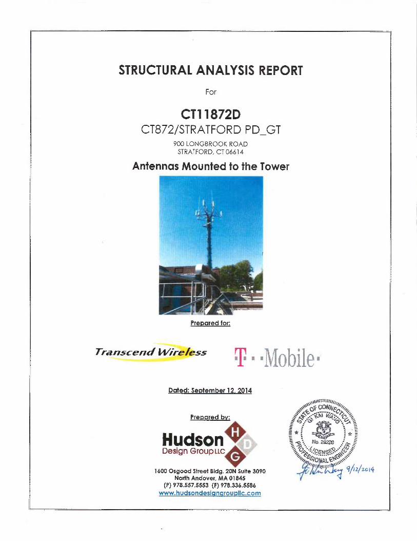
STRUCTURAL ANALYSIS REPORT
For
CT11872DCT872/STRATFORD PD_GT
900 LONGBROOK ROADSTRATFORD, CT 06614
Antennas Mounted to the Tower
Transcend Wire%ss ;~; ■ .~Qbile ~1
Dated: September 12, 2014
Prepared bv:
HudsonDesign Group ~~c
1600 Osgood Street Bldg. 20N Suite 3090North Andover, MA 01845
(P) 978.557.5553 (F) 978.336.5586www.hudsondesigngroupllc.com
`S~~L~i9:t:f! q/!I!/~/
:'C'! ''Q :, ~~t
# . ~r _
~~,~~ t~stf~: ~`~~~ 9~2~ZG~4
Prepared for:

HudsonDesign Group~~c
SCOPE OF WORK:
Hudson Design Group LLC (HDG) has been authorized by T-Mobile to conduct . astructural evaluation of the 50' guyed tower supporting the existing and proposed T-Mobile's antennas located at elevation 79' above ground level.
This report represents this office's findings, conclusions and recommendations pertainingto the support of T-Mobile's existing and proposed antennas listed below.
Record drawings of the existing tower prepared by Radian Communication Services,dated June 21, 2005, were available for our use. The previous structural analysis reportprepared by Tectonic Consultants, dated June 25, 2012, was also available andobtained for our use.
CONCLUSION SUMMARY:
Based on our evaluation, we have determined that the existing tower is in conformancewith the ANSI/TIA-222-F Standard for the loading considered under the criteria listed in thisreport. The tower structure is rated of 87.6 - (Guys at EL.69.8' Controllinq~.

HudsonDesign Group~~c -
APPURTANENCES CONFIGURATION:
Tenanfi Appurtenances Elev. Mount
20' Omni 92' T-Frame
16' Omni 90' T-Frame
6' Dipole 80' T-Frame
T-Mobile (6) AIR 21 Antennas 79' T-Frame
T-Mobile (3) TMA 79' T-Frame
T-Mobile (3) LNX-6515DS-VTM Antennas 79' T-Frame
T-Mobile (3) RRUS-11 79' T-Frame
(2) 3' Yagi 74' Tower Leg
3' Yagi 68' Tower Leg
Ground Plane Omni 64' Side Mount Standoff
3' Yagi 62' Tower Leg
*Proposed T-Mobile Appurtenances shown in Bold.
T-MOBILE EXISTING/PROPOSED COAX CABLES:
Tenant Cocix Cables Elev. Mount
T-Mobile (24) 7/8" Cables 79' Tower Face
T-Mobile (1) 1 5/8" Cable 79' Tower Face
*Proposed T-Mobile Appurtenances shown in Bold.
ANALYSIS RESULTS SUMMARY:
Componenfi Max. Stress Elev. of Component Pass/Fail Notes/CommentsRatio ff
Legs 26.2 ~ 67 - 82 PASS
Diagonals 42.4 ~ 52 - 67 PASS
Top Guts 16.2 % 52 - 67 PASS
Bottom Girts 17.8 % 32 - 37 PASS
Mid Girts 0.5 % 32 - 37 PASS
Guy A 87.6 ~ 69.8 PASS Controlling
Guy B 82.2 ~ 69.8 PASS
Guy C 83.0 % 69.8 PASS
Torque Arm 40.9 % 69.8 PASS

~ludsanDesign Group~~c
DESIGN CRITERIA:
1. EIA/TIA-222-F Structural Standards for Steel- Antenna Towers and AntennaSupporting Structures
County: FairfieldWind Load: 90 mph (fastest mile)
110 mph (3 second gust)Nominal Ice Thickness: 0.5 inch
2. Approximate height above grade to proposed antennas: 79'
*Calculations and referenced documents are attached*
[~~~~lul~~[~7►~~
1. The tower geometry, member sizes and material strength are as indicated in therecord drawings of the existing tower prepared by Radian CommunicationServices, dated June 21, 2005.
2. The appurtenances configuration is as stated in the previous structural analysisreport prepared by Tectonic Consultants, dated June 25, 2012. All antennas,coax cables and waveguide cables are assumed to be properly installed andsupported as per the manufacturer requirements.
3. The tower and supports are properly constructed and maintained. All structuralmembers and their connections are assumed to be in good condition and arefree from defects with no deterioration to its member capacities.
4. The support mounts and platforms are not analyzed and are consideredadequate to support the loading. The analysis is limited to the primary supportstructure itself.
5. All prior structural modification., if any, are assumed to be as per the datasupplied (if available), and installed properly.

Hudson ~:Design Group~~c '~
SUPPORT RECOMMENDATIONS:
HQG recommends that the proposed antennas and RRHs be mounted on the existing T-frame supported by the tower.
Reference HDG's Lafest Construction Drawings for all component and connectionrequirements (attached).
ONGOING AND PERIODIC INSPTECTION AND MAINTENANCE:
After the Contractor has successfully completed the installafion and the work has beenaccepted, the Owner will be responsible for the. ongoing and periodic inspection andmaintenance of the tower.
The owner shall refer to TIA/EIA-222-F for recommendations for maintenance. andinspection. The frequency of the inspection and maintenance intervals is to bedetermined by the owner based upon actual site and environmenfial conditions. It isrecommended that a complete and thorough inspection of the entire tower structuralsystem be performed at least yearly and more frequently as conditions warrant.According to TIA/EIA-222-F section 14.1, Note l: It is recommended that the structure beinspected after severe wind and/or ice storms or other extreme loading conditions.

HudsonDesign Group~~c
Photo 1: Photo illustrating the Tower with Appurtenances shown.

HudsonDesign Group~~c
CALCULATIONS

R=54.67 ft R=54.42 H (32)YLAIV
N
N
N
h ~ h ¢ h e'Q zm a a a
N
a
C
cV
a
x x x ?z z x ~ ~
J J J
nN
c
a _ ~ ~ a ~ _— ~ ~ E ~ m
_ (7 C7 (9o ~ o, o m a >m
f9 ~ J O D H ~ m li ~
82.0 R
DESIGNED APPURTENANCE LOADING~ TYPE ELEVATION TYPE ELEVATION
Omni 2 1/2"x20' 82 Andrew LNX-6515DS-VTM w/mount 79~ Omni 2'112"x16' 82 Pipe
6' Dipole g0 Ericsson RRUS11 79
i i i i iSM 4093 (T-MOBILE - ewsting) 79 Ericsson RRUS-11 79
69.8 ft
67.0 ft
52.0 ft
37.0 ft
32.0 ft
2454 Ib~
26538 Ib (A~dal)576 Ib-ft (Torque)
Air 21 antenna w/mowrt pipe 79 Ericsson RRUS-11 79
Air 2l antenna w/mountpipe 79 3'Yagi antenna 74
Air 21 antenna w/mount pipe 79 3' Yagi antenna 74
le 3 TMA 7g 3' Yagi antenna 68
le 3 TMA 79 3' Yagi antenna 62
le 3 TMA 7g Pirod 6' Side Mount StandoR (1) 61
crew LNX-6515D5-VTM w/mount 79 Ground Plane Omni 61e (T-MOBILE -proposed)
crew LNX-6515D5-VTM w/mount 79
MATERIAL STRENGTHGRADE Fy Fu GRADE Fy Fu
A572-42 42 ksi 60 ksi A36 36 ksi 58 ksi
TOWER DESIGN NOTES•1. Tower is located in Fairtield County, Connecticut.2. Tower designed fora 90 mph basic wind in accordance with the TIA/EIA-222-F Standard.3. Tower is also designed fora 78 mph basic wind with 0.50 in ice.4. Deflections are based upon a 50 mph wind.5. TOWER RATING: 87.6%
R=60.75 ft ~
Hudson Design Group, LLC1600 Osgood Street, Building 20 North, Suite
North Andover, MA 01845Phone: (978) 557-5553
9 Ib
~° CT91872D Stratford, CTProject: 50 ft Guyed Tower
ciient:T-MOBILE orawney:~, App'd:
code: TIA/EIA-222-F oate:09/11/14 scale: NTS

Job Page
tTQW~~' CT11872D Stratford, CT 1 of 9
Hudson Design Group, LLC Project Date
16000sgoodStreet, Building2oNorth, 50 ft Guyed Tower 18:24:34 09/11/14Suite 3090
North Andover, MA 01845 Client Designed byPhone: (978) 557-5553 T-M 0 B I L EFAX.• (978) 226-5586 kW
Tower In ut Data
The main tower is a 3x guyed tower with an overall height of 82.00 ft above the ground line.The base of the tower is set at an elevation of 32.00 ft above the ground line.The face width of the tower is 3.42. ft at the top and tapered at the base.This tower is designed using the TIA/EIA-222-F standard.The following design criteria apply:
Tower is located in Fairfield County, Connecticut.Basic wind speed of 90 mph.Nominal ice thickness of 0.5000 in.Ice density of 56 pcf.A wind speed of 78 mph is used in combination with ice.Temperature drop of 50 °F.Deflections calculated using a wind speed of 50 mph.Pressures are calculated at each section.Safety factor used in guy design is 2.Stress ratio used in tower member design is 1.333.Local bending stressas due to climbing loads, feed line supports, and appurtenance mounts are not considered.
Tower Section Geomet___ ~~_ ---_ ~____ ~_ .~-__ __~~-z_Tower ToN~er Assembly Description Section Nunsbe~^ SectionSection Elevation Database Width of Length
Sections
Tl 82.00-67.00 3.42 1 15.00T2 67.00-52.00 3.42 1 15.00T3 52.00-37.00 3.42 1 15.00T4 37.00-32.00 3.42 1 5.00
Tower Section Geomet cont'd
Tower Towe~~ Diagonal B~ acing Has Has Top Girt Bottom Gi~~tSection Elevation Spacing Type KBrace Hori ontals Offset Offset
Endft ft Panels in in
Tl 82.00-67.00 2.40 XBrace No No 2.0000 5.0000T2 67.00-52.00 2.40 K Brace Left No No 2.0000 5.0000T3 52.00-37.00 2.44 K Brace Left No No 2.0000 2.0000T4 37.00-32.00 1.44 X Brace No Yes 4.0000 4.0000
Tower Section Geomet cont'd
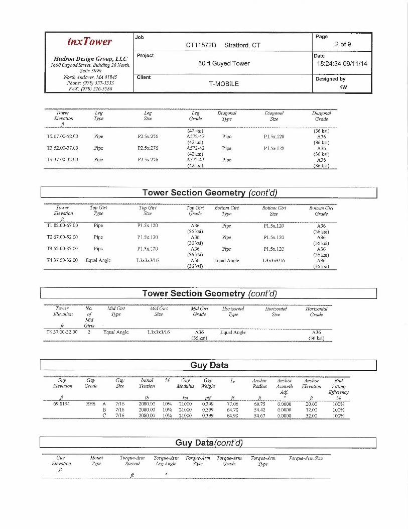
Tower Leg Leg i Leg Diagonal ~ Diagonal ~ DiagonalElevation Type Sue Grade Type Size Grade
T182.00-67.00 Pipe P2.Sx276 A572-42 Pipe P1.Sx.120 A36
Job Page
~~TOW~~' CT11872D Stratford, CT 2 of 9
Hudson Design Group, LLC Project Date
16o00sgoodStreet,Building2oNorth, 50 ft Guyed Tower 18:24:34 09/11/14Suite 3090
North Andover, MA 01845 Client Designed byPhone: (978) 557-5553 T-MOBILEFAX.• (978) 226-5586 kW
Tower Leg Leg Leg Diagonal Diagonal DiagonalElevation Type Sipe Grade Type Si:e Grade
(42 ksi) (36 ksi)T2 67.00-52.00 Pipe P2.Sx276 A572-42 Pipe P1.Sx.120 A36
(42 ksi) (36 ksi)T3 52.00-37.00 .Pipe P2.Sx276 A572-42 Pipe P1.Sx.120 A36
(42 ksi) (36 ksi)T4 37.00-32.00 Pipe P2.Sx.276 A572-42 Pipe A36
(42 ksi) (36 ksi)
Tower Section Geomet cont'd
Tower ~ Top Girt ~ Top Girt Top Girt Bottom Gi~~t Bottom Girt Bottom Gi~~tElevation Type ,size Grade Type Size Grade
T182.00-67.00 Pipe P1.Sx.120 A36 Pipe P1.Sx120 A36(36 ksi} (36 ksi)
TZ 67.00-52.00 Pipe P1.Sx.120 A36 Pipe P1.Sx.120 A36(36 ksi) (36 ksi)
T3 52.00-37.00 Pipe P1.Sx120 A36 Pipe P1.Sx.120 A36(36 ksi) (36 ksi)
T4 37.00-32.00 Equal Angle L3x3ac3/16 A36 Equal Angle L3ac3~/16 A36(36 ksi) (36 ksi)
Tower Section Geomet cont'd
Tower No. Mid Girt Mid Girt Mid Girt Horuontal Horizontal HorizontalElevation of Type Si e Grade Type Si.-e Grade
rrta. ft Girts
T4 37.00-32.00 2 Equal Angle L3x3~/16 A36 Equal Angle A36(36 ksi) ~ (36 ksi~~
Gu Data
Guy Guy ~~~Guy Inifial % Guy Guy L„ Anchor Anchor ~ Anchor ~ EndElevation Grade Sipe Tension Modulus Weight Radius fLimuth EZevation Fitting
Adj. Efficiencyft Zb ksi Plf .~ .ft .fr
69.8194 EHS A 7/16 2080.00 10% 21000 0399 77.06 60.75 0.0000 20,00 100%B 7/16 2080.00 10% 21000 0.399 64.70 54.42 0.0000 32.00 100°!0C 7/16 2080.00 10°/a 21000 0.399 64.90 54.67 0.0000 32.00 100%
Gu Data cont'd
Guy Mount Torque-Arm Torque-Arm Torque-Arnz Torque-Arnz Torgue-Arns Torque Arn: SeElevation Type Spread Leg Angle Sryle Grade Type

Job Page
~~~T~~~~ CT11872D Stratford, CT 3 of 9
Hudson Design Group, LLC Project Date
1600 osgooasn~eer, Burratng?oNoYrh, 50 ft Guyed Tower 18:24:34 09/11/14Suite 3090
North Andover, MA 01845 Client Designed byPhone: (978) 557-5553 T-MOBIL EFAX. (978) 226-5586 kW
Guy Mount Torque-Arni Torque-Aim Toque-Arne Torque-Arm Torgz~e-Arni Torque-ArmSi~eElevation Type Spread Leg Angle Sryle Grade Type
f~ °69.8194 Torque Arm 6.83 0.0000 Channel A36 Channel C12ac20.7
Feed Line/Linear A urtenances -Entered As Round Or Flat
Descrrptzon Face Allom Component Placement Total Nuneber Clem• Width or Perimeter Wezghfior Shield Type Number Per Row Spacing DzameterLeg ft in in in pIf
7/8 A Yes Ar (CfAe) 61.00 - 32.00 1 1 1.1100 1.1100 0.547/8 A Yes Ar (CfAe) 62.00 - 32.00 1 1 1.1100 1.1100 0.547/8 A Yes Ar (CfAe) 68.00 - 32.00 1 1 1.1100 1.1100 0.547/8 A Yes Ar (CfAe) 74.00 - 32.00 1 1 1.1100 1.1100 0.547/8 A Yes Ar (CfAe) 74.00 - 32.00 1 1 1.1100 1.1100 0.547/8 A Yes Ar (CfAe) 79.00 - 32.00 24 12 1.1100 1.1100 0.54
(T-MOBILE -existing)1 5/8 Fiber Cable A Yes Ar (CfAe) 79.00 - 32.00 1 1 1.9800 1.9800 1.04
(T-MOBILE -existing)7/8 A Yes Ar (CfAe) 82.00 - 32.00 2 2 1.1100 1.1100 0.54
Safety Line 3/S A Yes Ar (CfAe) 82.00 - 32.00 1 1 0.3750 03750 022
Discrete Tower Loads
Desc~~tptzon Face Offset Offsets: fL:imuth Placement C,3A_,~ CgAA Weightor Type Horz Adjustnsent Front SideLeg Lateral
Vert
ft .f~ fig ft~ lb
Omni 2 1/2"~0' B From Leg 4.00 0.0000 82.00 No Ice 5.00 5.00 40.000.00 1/2" Ice 7.03 7.03 76.9610.00
Omni 2 1/2"x16' B From Leg 4.00 0.0000 82.00 No Ice 4.00 4.00 35.000.00 1/2" Ice 5.63 5.63 64.638.00
6' Dipole A From Leg 4.00 0.0000 80.00 No Ice 0.90 0.90 15.000.00 1/2" Ice 1.52 1.52 22.490.00
************
SM 409-3 A None 0.0000 79.00 No Ice 22.47 22.47 1035.00(T-MOBILE -existing) 1/2" Ice 31.99 31.99 1500.00
(2) Air 21 antenna whnount A From Leg 4.00 0.0000 79.00 No Ice 6.74 5.60 101.90pipe 0.00 1/2" Ice 7.30 6.50 158.52
0.00(2) Air 21 antenna w/mount B From Leg 4.00 0.0000 79.00 No Ice 6.74 5.60 101.90
pipe 0.00 1/2" Ice 730 6.50 158.520.00
(2) Air 21 antenna whnount C From Leg 4.00 0.0000 79.00 No Ice 6.74 5.60 101.90pipe 0.00 1/2" Ice 7.30 6.50 158.52
0.00Style 3 TMA A Froin Leg 4.00 0.0000 79.00 No Ice 0.78 0.21 11.30
0.00 1/2" Ice 0.90 030 15.860.00

Job Page
~I~DWe~ CT11872D Stratford, CT 4 of 9
Hudson Design Gtoup, LLC Project Date
1600OsgoodStreet,Building2oNorth, 50 ft Guyed Tower 18:24:34 09/11/14Suite 3090
North Andover, MA 01845 Client Designed byPhone: (978) 557-5553 T-MOBILEFAX. (978) 226-5586 kW
Description Face Offset Offsets: .9~~niuth PZacement C,~A_g C,~AA Werghtor Type Hors Adjustment F~•ont SideLeg Lateral
Vertfqt ° ft ,ftZ ftZ Ib
Jq°
J4
Style 3 TMA B From Leg 4.00 0.0000 79.00 No Ice 0.78 0.21 11.300:00 1/2" Ice 0.90 030 15.860.00
Style 3 TMA C From Leg 4.00 0.0000 79.00 No Ice 0.78 0.21 11.300.00 1/2" Ice 0.90 0.30 15.860.00
Andrew LNX-6515DS-VTM A From Leg 4.00 0.0000 79.00 No Ice 11.72 1028 102.41w/mount pipe 0.00 1/2" Ice 12.44 11.81 196.22
(T-MOBILE -proposed) 0.00Andrew LNX-6515DS-VTM B From Leg 4.00 0.0000 79.00 No Ice 11.72 10.28 102..41
w/mount pipe 0:00 1/2" Ice 12.44 11.81 196220.00
Andrew LNX-6515DS-VTM C From Leg 4.00 0.0000 79.00 No Ice 11.72 10.28 102.41w/mount pipe 0.00 1/2" Ice 12.44 1.1.81 19622
0.00Ericsson RRUS-11 A From Leg 3.00 0.0000 79.00 No Ice 3.26 1.38 50.70
0.00 1/2" Ice 3.50 1.56 71.570.00
Ericsson RRUS-11 B From Leg 3.00 0.0000 79.00 No Ice 326 1.38 50.700.00 1/2" Ice 3.5~ 1.56 71.570.00
Ericsson RRUS-11 C From Leg 3.00 0.0000 79.00 No Ice 3.26 138 50.700.00 1/2" Ice 3.50 1.56 71.570.00
3' Yagi antenna A From Leg 2.00 0.0000 74.00 No Ice 0.70 035 10.000.00 1/2" Ice 0.95 0.48 3635O.OQ
3' Yagi anteana B From Leg 2.00 0.0000 74.00 No Ice 0.70 0.35 10.000.00 1/2" Ice 0.95 0.48 36.350.00
3' Yagi antenna C From Leg 2.00 0.0000 68.00 No Ice 0.70 0.35 10.00Q.00 1/2" Ice 0.95 0.48 36350.00
3' Yagi antenna C From Leg 2.00 0.0000 62.00 No Ice 0.70 035 10.000.00 1/2" Ice 0.95 0.48 35350.00
Pirod 6' Side Mount Standoff B From Leg 3.00 0.0000 61.00 No Ice 4.97 4.97 70.00(1) 0.00 1/2" Ice 6.12 6.12 130.00
0:00Ground Plane Omni B From Leg 6.00 0.0000 61.00 No Ice 1.90 1.90 25.00
0.00 1/2" Ice 2.70 2.70 39.003.00
Load Combinations
Comb. DescrzphonNo:1 bead Only2 Dead+Wind 0 deg - No Ice+Guy3 Dead+Wind 30 deg - No Ice+Guy4 Dead+Wind 60 deg - No Ice+Guy
Job Page
~n~7'c~wer CT11872D Stratford, CT 5 of 9
Hudson Design Group, LLC Project Date
160oOsgoodStreet,Building2oNorth, 50 ft Guyed Tower' 18:24:34 09/11/14Suite 3090
NorthAndaver, MA 01845 Client Designed byPhone: (978)557-5553 T-MOBILEFAX.' (978) 226-5586 kW
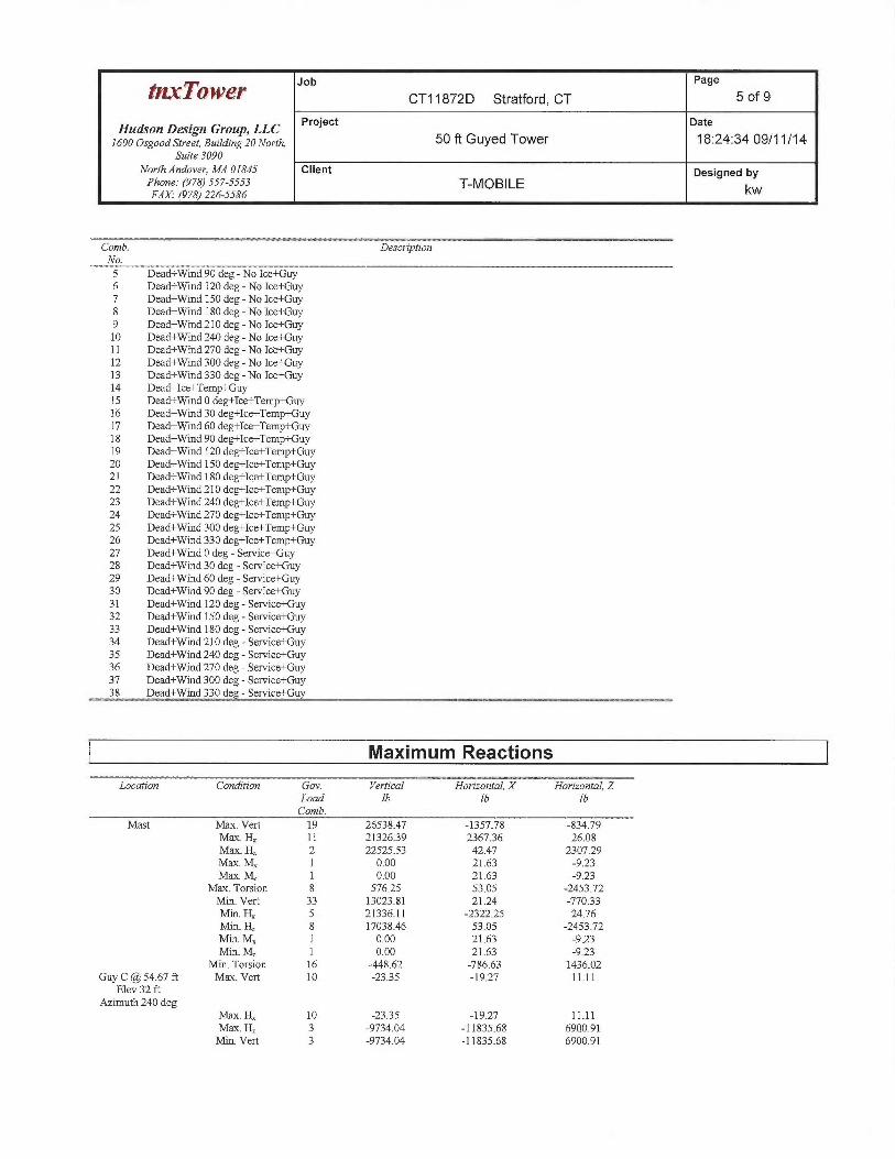
Comb. DescriptionNo.5 Dead+Wind 90 deg - No Ice+Guy6 Dead+Wind 120 deg - No Ice+Guy7 Dead+Wind 150 deg - No Ice+Guy8 Dead+Wind 180 deg - No Ice+Guy9 Dead+Wind 210 deg - No Ice+Guy10 Dead+Wind 240 deg - No Ice+Guy11 Dead+Wind 270 deg - No Ice+Guy
Dead+Wind 300 deg - No Ice+Guy13 Dead+Wind 330 deg - No Ice+Guy14 Dead+Ice+Temp+Guy15 Dead+Wind 0 deg+Ice+Temp+Guy16 Dead+Wind 30 deg+Ice+Temp+Guy17 Dead+Wind 60 deg+Ice+Temp+Guy18 Dead+Wind 90 deg+Ice+Temp+Guy19 Dead+Wind 120 deg+Ice+Temp+Guy20 Dead+Wind 150 deg+Ice+Temp+Guy21 Dead+Wind 180 deg+Ice+Temp+Guy22 Dead+Wind 210 deg+Ice+Temp+Guy23 Dead+Wind 240 deg+Ice+Temp+Guy24 Dead+Wind 270 deg+Ice+Temp+Guy25 Dead+Wind 300 deg+Ice+Temp+Guy26 Dead+Wind 330 deg+Ice+Temp+Guy27 Dead+Wind 0 deg - Service+Guy28 Dead+Wind 30 deg - Service+Guy29 Dead+Wind 60 deg - Service+Guy30 Dead+Wind 90 deg - Service+Guy31 Dead+Wind 120 deg -Service+Guy32 Dead+Wind 150 deg - Service+Guy33 Dead+Wind 180 deg - Service+Guy34 Dead+Wind 210 deg -Service+Guy35 Dead+Wind 240 deg -Service+Guy36 Dead+Wind 270 deg -Service+Guy37 Dead+Wind 300 deg - Service+Guy38 Dead+Wind 330 deg -Service+Guy
Maximum Reactions
Locafian Condition Gov. Vertical Horizanta7, X Horizontal, ZLoad Zb lb IbComb.
Mast MaY. Vert 19 26538.47 -1357.78 -834.79Mas. H,; 11 21326.39 236736 26.08Mas. H~ 2 22525.53 42.47 2307.29Max. M~ 1 0.00 21.63 -923Max. M~ 1 0.00 21.63 -923
Max. Torsion 8 576.25 53.05 -2453.72Min. Vert 33 13023.81 21.24 -770.33Min. Hx 5 21336.11 -2322.25 24.76Min. H 8 17038,46 53.05 -2453.72Min. Mx 1 0.00 21.63 -923Min. Mz 1 0.00 21.63 -923
Min. Torsion 16 -448.62 -786.63 1436.02Guy C @ 54.67 ft Mme. Vert 10 -2335 -19.27 11.11
Elev 32 ftAzimuth 240 deg
Max. Hx 10 -23.35 -1927 11.11Max. H~ 3 -9734.04 -11835.68 6900.91Min. Vert 3 -9734.04 -11835.68 6900.91

Job Page
~~p`w~x CT11872D Stratford, CT 6 of 9
Hudson Design Group, LLC Project Date
160oOsgoodStreet,Building2oNorth, 50 ft Guyed Tower 18:24:34 09/11/14Suite 3090
North Andover, MA 01845 Client Designed byPhone: (978) 557-5553 T-MOBILEFAX.' (978) 26-5586 kW
Location Condition Gov. Ttertical Horizontal X ~ Hoy i~ontal, ZLoad lb Ib IbComb.
Min. Hx 5 -9697.72 -11868.68 6742.47Min. H~ 10 -23.35 -19.27 11.11
Guy B @ 54.42 ft Mme. Vert 6 -24.06 19.75 11.36Elev 32 ft
Aznnuth 120 degMax. H,; 11 -9707.92 11825.02 6717.14MaY. H~ 13 -9762.06 1179608 6918.59Min. Vert 13 -9762.06 11796.08 6918.59Min. H, 6 -24.06 19.75 1136Min. H~ 6 -24.06 19.75 11.36
Guy A @ 60.75 ft Max. Vert 2 -8023 0.07 -71.61Elev 20 ft
Azimuth 0 degMme. Ha 24 -553133 244.87 -6622.87Mme. H~ 2 -80.23 0.07 -71.61Min. Vert 7 -11388.15 -95.81 -13594.19Min.. Ha 18 -5562.82 -245.31 -6660.19Min. Hz 7 -1138&.IS -95.81 -13594.19
Tower Mast Reaction Summa
Load Vertical Shea~~z Shear Overturning Ove~~turning TorgueCambinalzon Moment, M Moment, M
Zb lb db lb ft Zb-ft Zb ftDead Only 13199.70 -21.63 923 0.00 0.00 926Dead+Wind 0 deg - No 22525.53 -42.47 -2307.29 0.00 0.00 358.77Ice+GuyDead+Wind 30 deg - No 2064136 1159.23 -2018.79 0.00 0.00 410.06Ice+GuyDead+Wind 60 deg - No 16302.36 2059.94 -1220.50 0.00 0.00 422.84Ice+GuyDead+Wind 90 deg - No 2133b.11 2322.25 -24.76 0.00 0.00 130.43Ice+GuyDead+Wind 120 deg - No 23910.15 194732 1178.09 0.00 0.00 -98..00Ice+GuyDead+Wind 150 deg - No 22175.96 1088.46 209229 0.00 0:00 -292.72Ice+GuyDead+Wind 180 deg - No 17038.46 -53.05 2453.72 0.00 0.00 -576.25Ice+GuyDead+Wind 210 deg - No 22131.64 -1148.26 205930 0.00 0.00 -333.72Ice+GuyDead+Wind 240 deg - No 23884.12 -2000.87 1157.88 0.00 0.00 -246.05Ice+GuyDead+Wind 270 deg - No 21326.39 -236736 26.08 0.00 0.00 -101.65Ice+GuyDead+Wind 300 deg - No 16311.50 -2116.06 -12Q338 0.00 0:00 3939Ice+GuyDead+Wind 330 deg - No 20664.76 -1238.01 -2018.53 0.00 0.00 214.72Ice+GuyDead+Ice+Temp+Guy 19182.94 -3725 3.72 0.00 0.00 12.95Dead+Wind 0 25504.33 -58.01 -1646.15 0.00 0.00 368.78deg+Ice+Temp+GuyDead+Wind 30 24537.18 786.63 -1436.02 0.00 0.00 448.62deg+Ice+Temp+GuyDead+Wind 60 22576.56 1422.99 -854.34 0.00 0.00 372.84deg+Ice+Temp+Guy

Job Page
~~~~~~ CT11872D Stratford, CT 7 of 9
Hudson Design Group, LLC Project Date
160oOsgoodStreet,BuiZding20North, 50 ft Guyed Tower 18:24:34 09/11/14Suite 3090
North Andover, MA 01845 Client Designed byPhone: (978) 537-5553 T-MOBIL EFAX. (978) 226-5586 kW
Load Trertical Shearx Shear Overturning Overturning TorqueCombination Moment, M Moment, M
Zb Zb Ib Zb ft Ib-fz Ib-ftDead+Wind 90 24840.92 1620.43 -16.07 0.00 0.00 120.21deg+Ice+Temp+GuyDead+Wind 120 26538.47 1357.78 834.79 0.00 0.00 -81.26deg+Ice+Temp+GuyDead+Wind 150 25516.42 746.00 1477.65 0.00 0.00 -256.64deg+Ice+Temp+GuyDead+Wind 180 22698.14 -59.01 172124 0.00 0.00 -490.11deg+Ice+Temp+GuyDead+Wind 210 25433.55 -839.60 1446.50 0.00 0.00 -400.10deg+Ice+Temp+GuyDead+Wind 240 26465,02 -1443.06 814.54 0.00 0.00 -27324deg+Ice+Temp+GuyDead+Wind 270 24796.74 -1697.02 -17.11 0.00 0.00 -88.74deg+Ice+Temp+GuyDead+Wind 300 22586.49 -1507.99 -842.51 0.00 0.00 5539deg+Ice+Temp+GuyDead+Wind 330 24560.19 -894.86 -1433.48 0.00 0.00 149.09deg+Ice+Temp+GuyDead+Wind 0 deg - 13459.72 -22.71 -753.02 0.00 0.00 96.86Service+GuyDead+Wind 30 deg - 1343138 353.71 -650.77 0.00 0.00 107.29Service+GuyDead+Wind 60 deg - 13355.76 629.79 -371.78 0.00 0.00 87.75Service+GuyDead+Wind 90 deg - 13241.44 731.63 9.12 0.00 0.00 46.73Service+GuyDead+Wind 120 deg - 13144.97 631.22 39021 0:00 0.00 -1.78Service+GuyDead+Wind 150 deg - 13053.43 355.62 66$.87 0:00 0.00 -46.54Service+GuyDead+Wind 180 deg - 13023.81 -2124 77033 0.00 0.00 -80.46Service+GuyDead+Wind 210 deg - 13059.77 -39833 667.85 0.00 0.00 -91.48Service+GuyDead+Wind 240 deg - 1315533 -674.27 389.06 0.00 0.00 -71.08Service+GuyDead+Wind 270 deg - 13254.56 -775.05 8.67 0.00 0.00 -28.53Service+GuyDead+Wind 300 deg - 1336738 -674.09 -371.98 0.00 0.00 18.69Service+GuyDead+Wind 330 deg - 13437.64 -398.82 -650.86 .0.00 0.00 63.13Service+Guy
Solution Summa~a_ ___ _ _..~.__
Sum of Applied Forces Sunz of ReactionsLoad PX PY PZ PX PY PZ %ErrorCrnazb. Ib Ib Tb Zb Ib lb
1 0.00 -5727.63 0.00 0.03 5727.62 0.21 0:004%2 -026 -5738.10 -14182.42 025 5738.07 1418234 0:001%3 7091.46 -571531 -1227834 -7091.47 5715.25 12278.04 0.002%4 1228222 -5695.46 -7089.67 -1228239 5695.45 708927 0.003%5 14183.09 -5727.63 0.16 -141&2.92 5727.57 -0.03 0.001%6 12287.61 -5759.77 7093.07 -12287.33 5759.66 -7092.88 0.002%7 7091.90 -5739.94 12278.78 -7091.68 5739.86 -12278.62 0.002%8 0.26 -5717.16 14176.53 0.42 5717.15 -14176.49 0.004°/a9 -7091.46 -5739.94 12278.34 7091.24 5739.86 -12278.19 0.002%

Job Page
~1Z~~OWe1'' CT11872D Stratford, CT 8 of 9
Hudson Design Group, LLC Project Date
16000sgoodSmeet,Burldtng?oNorth, 50 ft Guyed Tower 18:24:34 09/11/14Suite 3090
North Andover, MA 01845 Client Designed byPhone: (978) 557-5553 T-MOBIL EFAX' (978) 226-5586 kW
Sum of Applied Forces ~ ~ Sum of ReactionsLoad PX PY PZ PX PY PZ % En~or•Comb. Zb 7b Ib Ib Zb lb10 -1228732 -5759.79 7092.62 12287.05 5759.68 -7092.43 0.002%11 -14183.09 -5727.62 -0.16 14182.92 5727.57 0.28 0.00112 -12282.50 -5695.48 -7090.13 12282.77 5695.46 7089.50 0.004%13 -7091.90 -571531 -12278.78 7091.90 5715.24 12278.48 0.002%14 0.00 -9845.02 0.00 0.01 9845.02 0.13 0.00115 -0.63 -9870.82 -12663.78 0.63 9870.76 12663.54 0.002%16 6337.08 -9814.68 -1096521 -6337.09 9814.65 10965.06 0.001%17 10977.42 -9765.76 -6334.19 -10977.42 9765.74 6333.85 0.002%18 12674.57 -9845.03 039 -12674.47 9845.00 -031 0.00119 10980.13 -9924.24 6336.48 -10979.95 9924.17 -633634 0.001%20 6338.16 -987537 1096630 -6338.02 987532 -1096621 0.001%21 0.63 -981923 12661.45 -030 9819.19 -1266].24 0.002%22 -6337.08 -9875.36 1096521 6336.94 987532 -10965.12 0.001%23 -10979.44 -992429 633535 1097925 992422 -6335.22 0.001%24 -12674.57 -9845.02 -0.39 12674.47 9844.99 0.47 0.001%25 -10978.11 -9765.81 -633531 10978.17 9765.79 6334.84 0.003%26 -6338.16 -9814.68 -1096630 6338.16 9814.65 10966.15 0.001%27 -0.08 -5730.86 -437729 0.08 5730.85 4376.98 0.004%28 2188.72 -5723.83 -3789.61 -2188.78 5723.82 3789.32 0.004%29 3790.81 -5717.70 -2788.17 -3790.56 5717.69 2188.04 0.004%30 4377.50 -5727.63 0.05 -4377.46 5727.63 0.01 0.001%31 3792.47 -5737.55 2189.22 -379237 5737.54 -2189.12 0.002%32 2188.86 -5731.43 3789.75 -2188.79 5731.42 -3789.69 0.001%33 0.08 -572439 4375.47 -0.07 572439 -437525 0.003%34 -2188.72 -5731.43 3789.61 2188.65 5731.42 -3789.56 0.001%35 -379238 -5737.55 2189.08 379229 5737.55 -2188.99 0.002%36 -4377.50 -5727.62 -0.05 4377.46 5727.62 0.10 0.001%37 -3790.90 -5717.70 -218831 3790.65 5717.70 2188.18 0.004%38 -2188.86 -5723.82 -3789.75 2188.91 5723.82 3789.47 0.004%
Maximum Tower Deflections -Service Wind. _._
Secrion Elevation Horz Gov. Talt TivistNo. Deflection Load
ft in Comb. °Tl 82 - 67 0.998 33 0.1040 0.0385T2 67 - 52 0.685 33 0.0881 0.0288T3 52 - 37 0.428 33 0.0917 0.0321T4 37 - 32 0.114 33 0.1053 0.0263
Critical Deflections and Radius of Curvature -Service Wind
Elevation Appu~~tenance Gov. Deflection Tilt Twist Radius ofLoad Curvature
ft Consb. in ft82.00 Omni 21/2"~c20' 33 0.998 0.1040 0.0385 6562480.00 6' Dipole 33 0.954 0.1013 0.0367 6562479.00 SM 409-3 33 0.932 0.1000 0.0357 6562474.00 3' Yagi antenna 33 0.824 0.0938 0.0317 4101569.82 Guy 33 0.738 0.0898 0.0295 2738068.00 3' Yagi antemia 33 0.703 0.0886 0.0290 2566262.00 3' Yagi antenna 33 0.598 0.0872 0.0297 5682361.00 Puod 6' Side Mount Standoff (1) 33 0.581 0.0873 0.0300 83506

Job Page
tnxTQwer CT11872D Stratford, CT 9 of 9
Hudson Design Gtoup, LLC Project Date
16000sgoodStreet, Building 20 North, 50 ft Guyed Tower 18:24:34 09/11/14Suite 3090
NorthAndaver,MA01845 Client Designed byPhone: (978) 557-5553 T-MOBIL EFAX.• (978) 226-5586 kW
Section Ca acit Table
Secrion Elevation Component Sipe Critical P SF*Pa»o„, % Pass
No. .ft Type Element Zb Zb Capacity Fail
Tl 82 - 67 Leg P2.Sx.276 3 -18049.50 68948.49 262 PassT2 67 - 52 Leg P2.Sx.276 47 -1470630 58516.83 25.1 PassT3 52 - 37 Leg P2.Sx.276 75 -13874.50 58098.14 23.9 PassT4 37 - 32 Leg P2.Sx276 102 -11795.60 70683.79 16.7 PassTl 82 - 67 Diagonal P1.Sx.120 13 -4365.28 12871.63 33.9 PassT2 67 - 52 Diagonal P1.Sx.120 70 -3990.11 9417.08 42.4 PassT3 52-37 Diagonal P1.Sx120 83 -1603.19 9370.23 17.1 PassTl 82 - 67 Top Girt P1.Sx.120 6 -250.71 10813.11 23 PassT2 67 - 52 Top Girt P1.5x120 50 -175239 10813.11 16.2 PassT3 52 - 37 Top Girt P 1.5x.120 78 -266.61 10813.11 2.5 PassT4 37 - 32 Top Girt L3a~3~/16 104 1176.95 31384.15 3.8 PassTl 82 - 67 Bottom Girt P1.Sx.120 7 -1650.44 10813.11 153 PassT2 67 - 52 Bottom Girt P1.Sx.120 54 -40120 10813.11 3.7 PassT3 52 - 37 Bottom Girt Pl.5x.120 80 1510.80 14979.45 10.1 PassT4 37 - 32 Bottom Girt L3~~/16 107 -764.77 30321.75 17.8 PassT4 37 - 32 Mid Girt L3~~/16 113 -118.91 21804.95 0.5 PassTl 82 - 67 Guy A@69:8194 7116 123 9108.11 10400.00 87.6 PassTl 82 - 67 Guy [email protected] 7/16 120 8549.42 10400.00 82.2 PassTl 82 - 67 Guy [email protected] 7116 116. 8627.04 10400.00 83.0 PassTI 82 - 67 Torque Arm C12~c20.7 126 -4221.81 702657.52 40.9 Pass
Leg (Tl) 262 PassDiagonal 42.4 Pass(T2)
Top Girt 16.2 Pass(T2)
Bottom Girt 17.8 Pass(T4)
Mid Girt 0.5 Pass(T4)
Guy A (TI) 87.6 PassGuy B (Tl) 822 PassGuy C (Tl) 83.0 PassTorque Arm 40.9 PassTop (Tl)RATING = 87.6 Pass

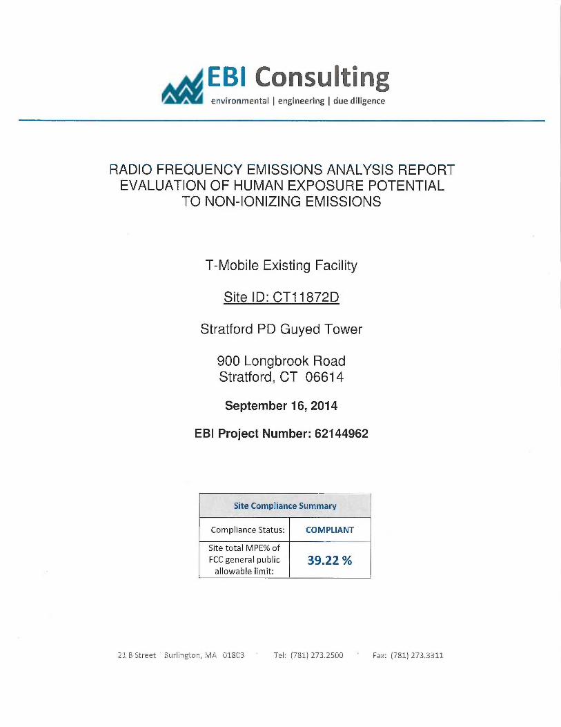
EBI Consulting~, environmental ~ engineering ~ due diligence
RADIO FREQUENCY EMISSIONS ANALYSIS REPORTEVALUATION OF HUMAN EXPOSURE POTENTIAL
TO NON-IONIZING EMISSIONS
T-Mobile Existing Facility
Site ID: CT11872D
Stratford PD Guyed Tower
900 Longbrook RoadStratford, CT 06614
September 16, 2014
EBI Project Number: 62144962
Site Compliance Summary
Compliance Status: COMPLIANT
Site total MPE% of
FCC general public 39,22allowable limit:
22 B Streei Burlington, MA Q1803 Tel: (781) 273.2500 Fax: (781} 273.3311
EBI Consulting~, environmental ~ engineering ~ due diligence
September 16, 2014
T-Mobile USAAttn: Jason Overbey, RF Manager35 Griffin Road SouthBloomfield, CT 06002
Emissions Analysis for Site: CT11872D —Stratford PD Guyed Tower
EBI Consulting was directed to analyze the proposed T-Mobile facility located at 900 Longbrook Road,
Stratford, CT, for the purpose of determining whether the emissions from the. Proposed T-Mobile
Antenna Installation located on this property are within specified federal limits.
All information used in this report was analyzed as a percentage of current Maximum Permissible
Exposure (% MPE) as listed in the FCC OET Bulletin 65 Edition 97-01and ANSI/IEEE Std C95.1. The
FCC regulates Maximum Permissible Exposure in units of microwatts per square centuneter (µW/crn2).
The number of µW/cm2 calculated at each sample point is called the power density. The exposure limit
for power density varies depending upon the frequencies being utilized. Wireless Carriers and Paging
Services use different frequency bands each with different exposure limits, therefore it is necessary to
report results and limits in terms of percent MPE rather than power density.
All results were compared to the FCC (Federal Communications Commission) radio frequency exposure
rules, 47 CFR 11307(b)(1) — (b)(3), to determine compliance with the M~imum Permissible Exposure
(MPE) limits for General Population/Uncontrolled environments as defined below.
General population uncontrolled exposure limits apply to situations in which the general public may beexposed or in which persons who are exposed as a consequence of their employment may not be made
fully aware of the potential for exposure or cannot exercise control over their exposure. Therefore,
members of the general public would. always be considered under this category when exposure is not
employment related, for example, in the case of a telecommunications tower that exposes persons in anearby residential area.
Public exposure to radio frequencies is regulated and enforced in units of microwatts per square
centimeter (µW/cmZ). The general population exposure limit for the 700 MHz Band is 467 µW/cmZ, and
the general population exposure limit for the PCS and AWS bands is 1000 µW/cmZ. Because each carrierwill be using different frequency bands, and each frequency band has different exposure limits,. it is
necessary to report percent of MPE rather than power density.
21 B Street Burlington, MA 01803 Tel: (781j 273.2500 Fax: (781} 273.3311.
EBI Consulting,~, environmental ~ engineering ~ due diligence
OccupationaUcontrolled exposure limits apply to situations in which persons are exposed as a
consequence of their employment and in which those persons who are exposed have been made fully
aware of the potential for exposure and can exercise control over their exposure. OccupationaUcontrolled
exposure limits also apply where exposure is of a transient nature as a result of incidental passage through
a location where exposure levels may be above general population/uncontrolled limits (see below), as
long as the exposed person has been made fully aware of the potential for exposure and can exercise
control over his or her exposure by leaving the area or by some other appropriate means.
Additional details can be found in FCC OET 65.
CALCULATIONS
Calculations were done for the proposed T-Mobile Wireless antenna facility located at 900 Longbrook
Road, Stratford, CT, using the equipment information listed below. All calculations were performed per
the specifications under FCC OET 65. Since T-Mobile is proposing highly focused directional panel
antennas, which project most of the emitted energy out toward the horizon, all calculations were
performed assuming a lobe representing the maximum gain of the antenna per the antenna manufactures
supplied specifications, minus 10 dB, was focused at the base of the tower. For this report the sample
point is the top of a 6 foot person standing at the base of the tower.
For all calculations, all equipment was calculated using the following assumptions:
1) 2 GSM channels (PCS Band - 1900 MHz) were considered for each sector of the proposed
installation. These Channels have a transmit power of 30 Watts per Channel
2) 2 UMTS channels (AWS Band — 2100 MHz) were considered for each sector of the proposed
installation. These Channels have a transmit power of 30 Watts per Channel.
3) 2 LTE channels (AWS Band — 2100 MHz) were considered for each sector of the proposed
installation. These Channels have a transmrt power of 60 Watts per Channel.
4) 1 LTE channel (700 MHz Band) was considered for each sector of the proposed installation.
This channel has a transmit power of 30 Watts.
5) All radios at the proposed installation were considered to be running at full power and were
uncombined in their RF transmissions paths per carrier prescribed configuration. Per FCC
OET Bulletin No. 65 -Edition 97-01 recommendations to achieve the m~imum anticipated
value at each sample point, all power levels emitting from the proposed antenna installation
are increased by a factor of 2.56 to account for possible in-phase reflecrions from the
surrounding environment. This is rarely the case, and if so, is never continuous.
21 B Street ~ Burlington, MA 01843 Tel: {781) 273.25~Q Fax: (781) 273.3311
EBI Consulting~ environmental (engineering ~ due diligence
6) For the following calculations the sample point was the top of a six foot person standing at
the base of the tower. The maximum gain of the antenna per the antenna manufactures
supplied specifications minus 10 dB was used in this direction. This value is a very
conservative estimate as gain reductions for these particular antennas are typically much
higher in this direction.
7) The antennas used in this modeling are the Ericsson AIR21 S4A/B2P for 1400 MHz (PCS)
and 2100 MHz (AWS) channels and the Commscope LNG-6515DS-VTM for 7001VIHz
channels. This is based on feedback from the carrier with regards to anticipated antenna
selection. The Ericsson AIR21 B4A/B2P has a ma~mum gain of 15.9 dBd at its main lobe.
The Commscope LNX-6515DS-VTM has a m~imum gain of 14.6 dBd at its main lobe.
The ma~mum gain of the antenna per the antenna manufactures supplied specifications,
minus 10 dB, was used for all calculations. This value is a very conservative estimate as gain
reductions for these particular antennas are typically much higher in this direction.
8) The antenna mounting height centerline of the proposed antennas is 79 feet above ground
level (AGL).
9) Emissions values for additional carriers were taken from the Connecticut Suing Council
active database. Values in this database are provided by the individual carriers themselves.
All calculations were done with respect to uncontrolled /general public threshold limits.
21 B Street 'Burlington, MA 41803 TeL• (781) 273.2500 Fax: (781) 273,3311

EBI Consulting,s, environmental ~ engineering ~ due diligence
T-Mobile Site Inventory and Power Data
Sector: A Sector: B Sector: CAntenna #: 1 Antenna #: 1 Antenna #: 1
Ericsson AIR21 Ericsson AIR21 Ericsson AIR21Make/ Model:
B4A/B2P Make I Model•
B4A/B2P Make 1 Model_
B4A/B2PGain: 15.9 dBd Crain: 15.9 dBd Gaiu: 15.9 dBd
Hei ht (AGL)_ 79 Hei ht (AGL): 79 Hei ht (AGL): 79
FrequencpBands 1900 MHz(PGS) /
Frequency Bands 1900 MHz(PCS) /
Frequency Bands 1900 MI~z(PCS) /
2100 MHz (AWS) 2100 MHz (AWS) 2100 MHz (AWS)Channel Count 2 Channel Count 2 # PCS Channels: 2
Total TX Power: 120 Total TX Power. 120 # AWS Channels: 120ARP (~: 1.,906.06 ERP (VV)_ 1,906.06 ERP (4V): 1,906.06
Antenna Al MPE%n 3.15 Antenna B 1 MPE% 3.15 Antenna Cl MPE%o 3.15
Antenna #: 2 Antenna #: 2 Antenna #: 2Ericsson AIRZl Ericsson AII221 Ericsson A1R21
Make/Model: B4A/B2P
Make/Model• B4A/BZP
MakeJModel: B4A/B2P
Gain: 15:9 dBd Gain: 15.9 dBd Gain: 15.9 dBdHeight (AGI.): 79 Height (AGL): 79 Height (AGL): 79
Frequency Bands 1900 MHz(PCS) /
Frequency Bands 1900 MHz(PCS) /
~equencyBands 1900 MHz(PCS) /
2100 MHz (AWS) 2100 MHz (AWS) 2100 MHz (AWS)Channel Count 4 Channel Count 4 Channel Count 4
Total T'X Power: 120 Total TX Power: 120 Total TX Power: 120EE2P (PTj: 1,906.06 ERP (VJ)_ 1,906.06 ERP (V~: 1,906.06
Antenna AZ MFE% 3.15 Antenna B2 MPE ro 3.15 Antenna C2 MPE°'a 3.15
Antenna #: 3 Antenna #: 3 Antenna #: 3Commscope LNX- Commseope LNX- Commscope LNX-
Make /Model: 6515DS-VTM
Make /Model: 6515DS-VT'M
Make !Model- 6515DS-VTM
Gain: 14.6 dBd Gain._ 14.6 dBd Csain: 14.6 dBdHei t (AGL). 79 Hei t (AGL): 79 Hei ht (AGL): 79
Fre uency Bands 700 Mhz Fr uency Bands 700 Mhz Fre uenc Bands 700 MhzChannel Count 1 Channel Count 1 Channel Count 1
Total TX Power: 30 Total TX Pawer. 30 Total TX Power. 30ERP ~: 44537 II2P (lam: 445.37 ERP (VJ): 44537
Antenna A3 MPE%n 1.25 Antenna B3 MPE% 1.25 Antenna C3 MPE% 1.25
Site Com osite MPE%Carrier MPE%
T-Mobile 22.65
SPD -Omni 1.70 %
SPD - Yagi 136 %
SPD - Yagi 1.36
SPD - 63fta 2.88 %
SPD - 63ftb 6.40 %
SPD - 53ft 2.88 %a
Site Total MPE %: 39.22 %
T-Mobile Sector 1 Total: 7.55 %oT-Mobile Sector 2 Total: 7.55T-Mobile Sector 3 Total: 7.55 %
Site Total: 39.22
21 B Street Burlington, MA 01&03 Tel: X781) 273.2500 Fax: (781) 27 .3311
~EBI Consulting♦ enUironmental ~ engineering ~ due diligence
Summary
All calculations performed for this analysis yielded results. that were within the allowable limits for
general public exposure to RF Emissions.
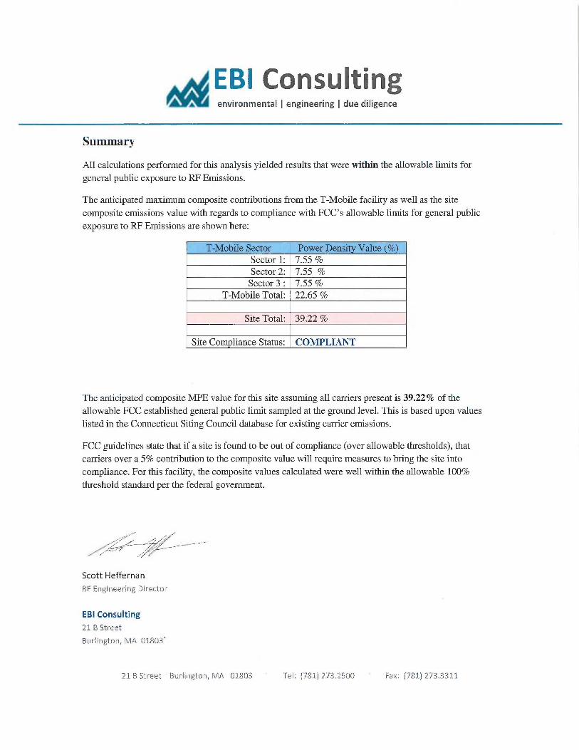
The anticipated ma~mum composite contributions from the T-Mobile facility as well as the site
composite emissions value with regards to compliance with FCC's allowable limits for general public
exposure to RF Emissions are shown here:
T-Mobile Sector Power Density Value (%)Sector 1: 7.55 %Sector 2: 7.55Sector 3 : 7.55
T-Mobile Total 22.65 %
Site Total: 39.22
Site Compliance Status: COMPLIANT
The anticipated composite MPE value for this site assuming all carriers present is 39.22°Io of the
allowable FCC established general public limit sampled at the ground level. This is based upon values
listed in the Connecticut Siting Council database for e~sting carrier emissions.
FCC guidelines state that if a site is found to be out of compliance (over allowable thresholds), that
carriers over a 5% contribution to the composite value will require measures to bring the site into
compliance. For this facility, the composite values calculated were well within the allowable 100%
threshold standard per the federal government.
' F
/// . % /^~~ J~~~-
Scott Heffernan
RF Eragiraeering director
EBI Consulting
21 B Street
Burlington, MA 018Q3~
21 6 Street Burlington, MA 018 3 Tel: (781 273.25 0 Fax: (781 273.3312