good vibrations: report from the commissioning of crires filea cryogenic wollaston prism on a...
TRANSCRIPT
32 The Messenger 126 – December 2006
Telescopes and Instrumentation
Hans Ulrich Käufl, Paola Amico, Pascal Ballester, Eduardo Bendek, Peter Biereichel, Paul Bristow, Mark Casali, Bernhard Delabre, Reinhold Dorn, Siegfried Eschbaumer, Raul Esteves, Enrico Fedrigo, Gert Finger, Gerhard Fischer, Gordon Gillet, Domingo Gojak, Gotthard Huster, Yves Jung, Florian Kerber, Jean-Paul Kirchbauer, Jean-Louis Lizon, Enrico Marchetti, Leander Mehrgan, Manfred Meyer, Alan Moor-wood, Sylvain Oberti, Jean-François Pirard, Jérome Paufique, Eszter Pozna, Francesca Primas, Ricardo Schmutzer, Andreas Seifahrt, Ralf Siebenmorgen, Armin Silber, Alain Smette, Barbara Sokar, Jörg Stegmeier, Lowell Tacconi-Garman, Sebastien Tordo, Stefan Uttenthaler, Ueli Weilenmann (all ESO)
CRIRES is a cryogenic, pre-dispersed, infrared echelle spectrograph designed to provide a nominal resolving power l /Dl of 105 between 1000 and 5 000 nm for a nominal slit width of 0.2 ?. The CRIRES installation at the Nasmyth fo-cus A of the 8-m VLT UT1 (Antu) marks the completion of the original instru-mentation plan for the VLT. A curvature sensing adaptive optics system feed is used to minimise slit losses and to provide 0.2 ? spatial resolution along the slit. A mosaic of four Aladdin InSb-ar-rays packaged on custom-fabricated ceramic boards has been developed. It provides for an effective 4 096 × 512 pix-el focal plane array to maximise the free spectral range covered in each expo-sure. Insertion of gas cells is possible in order to measure radial velocities with high precision. Measurement of circular and linear polarisation in Zeeman sen-sitive lines for magnetic Doppler imag-ing is foreseen but not yet fully imple-mented. A cryogenic Wollaston prism on a kinematic mount is already incor-porated. The retarder devices are lo-cated close to the Unit Telescope focal plane. Here we briefly recall the ma- jor design features of CRIRES and de-scribe the commissioning of the instru-ment including a report of extensive laboratory testing and a preview of as-tronomical results. Thanks to the strong efforts of the CRIRES commissioning team and all other ESO staff involved, it was possible to include the instrument
in the general ESO call for proposals for Period 79.
The CRIRES spectrograph is the last in-strument of the first-generation VLT instru-mentation plan (D’Odorico et al. 1991). It was included in the very first call for VLT instruments in 1989. Then several options for this instrument were discussed dur-ing the Workshop on High Resolution Spectroscopy with the VLT held at ESO in 1992 (Ulrich 1992). By then, however, in-frared astronomy had just left behind the era of single-pixel detectors. In fact in those days there was even a strong case to build a Fourier-transform spectrome-ter, rather than a grating spectrograph. The small detector formats of those days would have left a grating spectrograph with a rather limited spectral coverage. The trade-offs then were analysed in some detail at ESO. By 1997, however, de-tector formats and the respective perfor-mance had developed sufficiently to se-cure the formal inclusion of CRIRES in the VLT instrumentation plan. The CRIRES instrument is an entirely ESO internal pro-ject. The instrument team was advised, as for all other VLT instruments, by a spe-cific science team1. As there was some competition for the limited resources with-in ESO, the project proceeded slowly but steadily. Finally the instrument had its real start in 1999. The preliminary design review (PDR) was held in April 2000 and the final design review (FDR) took place in October 2001. Assembly and integra- tion progressed and in January 2005 the team celebrated ‘first light’ in the labo-ratory. For the rest of 2005 the team was busy bringing the spectrograph in line with specifications, understanding and fixing many problems. Finally, in Decem-ber 2005 the two independent subsys-tems of CRIRES, the vacuum vessel with the cryogenic assembly and the adaptive optics part, were merged and integrated. This marked the start of end-to-end test-ing. Since then nearly all tests required to pass the Preliminary Acceptance Europe (PAE) review could be performed. CRIRES was then again split and the adaptive optics part sent to Paranal to be commis-
sioned independently (c.f. Käufl et al. 2006). Meanwhile the cryostat underwent last modifications and tests to arrive at a state that also the basic spectrograph was itself ready for the review proc- ess. The PAE review meeting was held on 13 April 2006 and the green light for shipping – after completing the essentials from the action item list – was granted on 25 April. Thereafter, in a process which in retrospect resembles a miracle, CRIRES was literally ripped to pieces, packed, collected by the shipper in Gar-ching on 28 April and shipped to Paranal to arrive in record time. Unpacking could commence on 7 May, only nine days later. The cryostat was pre-erected in the laboratory, while the (heavy) instrument support was mounted immediately direct-ly to the Nasmyth platform of UT1. In spite of the extremely fast packing, ship-ping and unpacking not even minor trans-port damage was encountered. The in-strument was then tested for two weeks in the integration lab of the VLT control building. Laboratory testing ended on 25 May and, after warm-up of CRIRES, a few minor last-minute changes were ap-plied. CRIRES was then transferred to its final location for the foreseeable future, the Nasmyth platform A of UT1 (Figure 1).
Main characteristics
Figure 2 shows the general layout of CRIRES and Figure 3 gives an impression of the cryogenic instrument. The instru-ment main characteristics are summa-rised in Table 1. The instrument and its operations concept have been described in some detail by Käufl et al. 2004. For the latest state the reader is referred to the CRIRES User’s manual: http://www.eso.org/instruments/crires/
For calibration a physical model approach has been taken. In spite of the crowded scheme, as shown in Figure 2, CRIRES is from the model point of view rather sim-ple: once the telescope/slit-viewer scale in the slit-plane have been calibrated, the pre-slit optics has no real influence any-more on spectral and spatial calibration. It it thus not part of the model. The pre-disperser can be easily represented by a re-imager with a magnification close to unity and, according to the optical design calculations, negligible distortion. The
Good Vibrations: Report from the Commissioning of CRIRES
1 The members of the CRIRES science team are: Catherine de Bergh, Meudon; Ewine van Dishoek, Leiden; Bengt Gustafsson (chair), Uppsala; Artie Hatzes, Tautenburg; and Ken Hinkle, Tucson.
33The Messenger 126 – December 2006
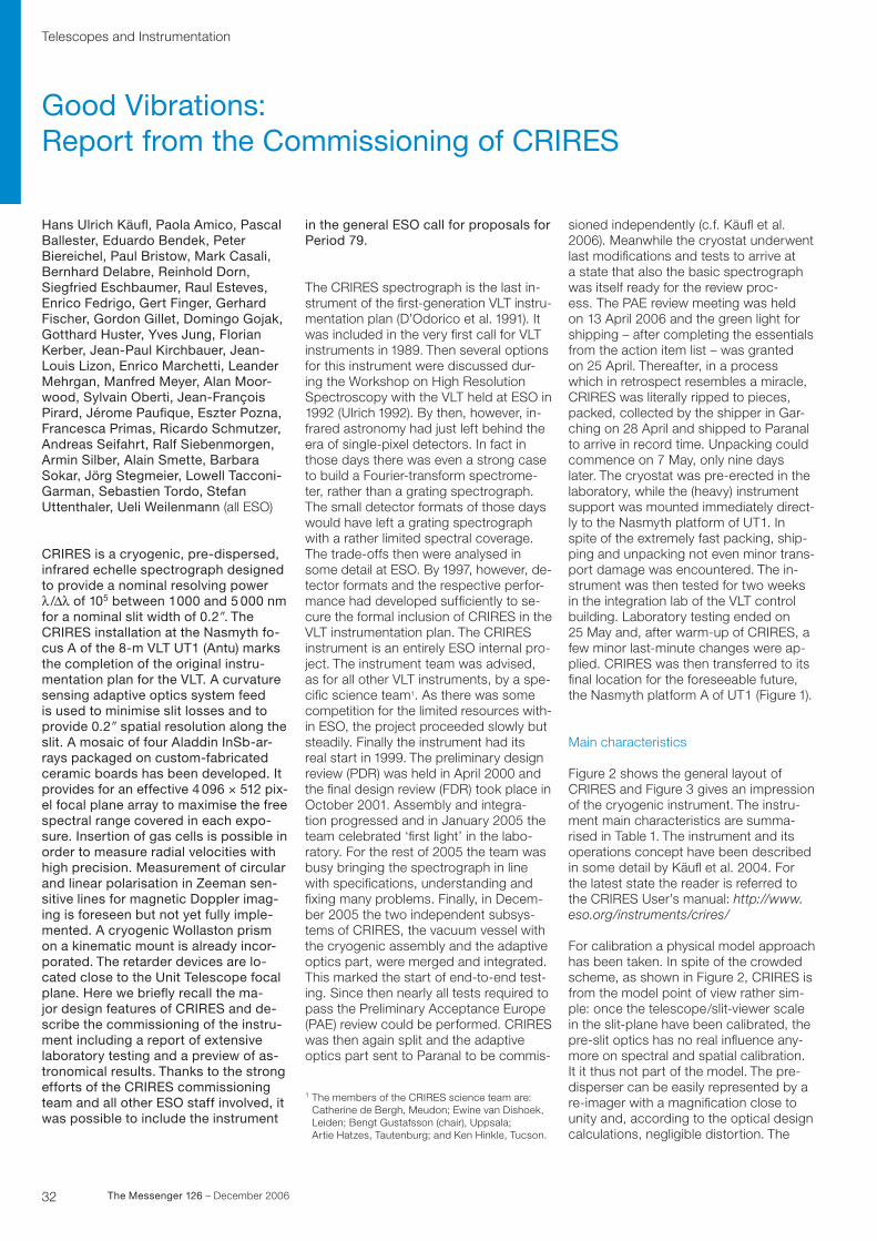
Figure 1: CRIRES at its final destination, the Nasmyth platform A of UT1 (Antu). It is still amaz- ing that even a rather big instrument is literally dwarfed by the VLT. On the right side of the blue Nasmyth adaptor the ‘black box’ holding the de-rotator and the MACAO adaptive optics system can be seen. Below this box are calibration lamps and an integrating sphere. Inside the box is a motorised linear stage to position the gas cells, the retarder plates and other auxiliary optical elements. The gray cylindrical structure is the vacuum vessel contain- ing the instrument cryogenic opto-mechanical as-sembly. CRIRES is cooled to ~ 65 K.
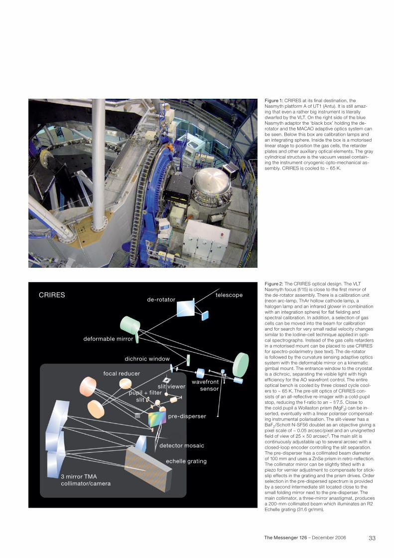
de-rotatortelescope
deformable mirror
CRIRES
wavefrontsensorslit viewer
pre-disperser
detector mosaic
echelle grating
3 mirror TMAcollimator/camera
focal reducer
dichroic window
slitpupil + filter
Figure 2: The CRIRES optical design. The VLT Nasmyth focus (f/15) is close to the first mirror of the de-rotator assembly. There is a calibration unit (neon arc-lamp, ThAr hollow cathode lamp, a halogen lamp and an infrared glower in combination with an integration sphere) for flat fielding and spectral calibration. In addition, a selection of gas cells can be moved into the beam for calibration and for search for very small radial velocity changes similar to the Iodine-cell technique applied in opti- cal spectrographs. Instead of the gas cells retarders in a motorised mount can be placed to use CRIRES for spectro-polarimetry (see text). The de-rotator is followed by the curvature sensing adaptive optics system with the deformable mirror on a kinematic gimbal mount. The entrance window to the cryostat is a dichroic, separating the visible light with high efficiency for the AO wavefront control. The entire optical bench is cooled by three closed cycle cool-ers to ~ 65 K. The pre-slit optics of CRIRES con-sists of an all-reflective re-imager with a cold-pupil stop, reducing the f-ratio to an ~ f/7.5. Close to the cold pupil a Wollaston prism (MgF2) can be in-serted, eventually with a linear polariser compensat-ing instrumental polarisation. The slit-viewer has a BaF2/Schott N-SF56 doublet as an objective giving a pixel scale of ~ 0.05 arcsec/pixel and an unvignetted field of view of 25 × 50 arcsec2. The main slit is continuously adjustable up to several arcsec with a closed-loop encoder controlling the slit separation. The pre-disperser has a collimated beam diameter of 100 mm and uses a ZnSe prism in retro-reflection. The collimator mirror can be slightly tilted with a piezo for vernier adjustment to compensate for stick-slip effects in the grating and the prism drives. Order selection in the pre-dispersed spectrum is provided by a second intermediate slit located close to the small folding mirror next to the pre-disperser. The main collimator, a three-mirror anastigmat, produces a 200-mm collimated beam which illuminates an R2 Echelle grating (31.6 gr/mm).
34 The Messenger 126 – December 2006
ZnSe-prism refractive index is parameter-ised with a Sellmeier formula. These parameters have been measured at oper-ating temperature using the CHARMS facility at NASA-GSFC. Using (or one might even say abusing) CRIRES, the co-efficients have been verified in the range ~ 60–80 K. To have a sufficient line density, the ThAr infrared spectrum has been explored and a corresponding hollow cathode lamp has been incorpo-rated into the instrument (Figure 4). Us-ing this facility as well as the N2O gas cell the physical model is being calibrated. This model will soon be available within the instrument pipeline. These modelling efforts are based on established princi-ples developed for Echelle spectrographs and have been applied previously to other ESO instruments (e.g. UVES).
Figure 5 shows the detector mosaic that is the ‘eyes’ of CRIRES.
Summary of status
At this point CRIRES is provisionally com-missioned. While the activities in August 2006 and the first science verification observations were still plagued with align-ment and focus problems, all these issues were solved in a final – at least for the moment – intervention to the instru-ment in September. The major specifica-tions are met and the performance has been re-checked at the telescope. The details are condensed into the CRIRES exposure time calculator. However, al-ready after the second commissioning run in August 2006, which was followed by four nights of early science verifica-tion observations, CRIRES and the asso-ciated software and documentation had reached a status which made it pos-sible to include the instrument, basically unrestricted, in the regular call for pro-posals for Period 79. Many thanks go at this point to the colleagues who parti-cipated in the two calls for science verifi-cation and who have provided the team with valuable feed-back. The response from the community to the very first regu-lar call was quite encouraging: more than 60 proposals asking for more than 160 nights!
In spite of all the efforts of the team, there is still a long list of action items to be completed. Fortunately, this list does not contain show-stoppers. Moreover, there is some room for improvements to the instrument. In the coming months the team will gradually work on the action item list, and CRIRES users can ex- pect that the instrument performance will slightly improve its use.
Before the start of observations in Peri-od 79 there will be one final commission-ing run and a third call for science verifi-cation proposals. In parallel with the final commissioning and to the start of opera-tions the polarimetric mode will be imple-mented, including a calibration module allowing to rigorously calibrate the instru-ment such that all four Stokes parameters can be measured. This will happen ‘invis-ibly’ for operations and first astronomi- cal commissioning of spectropolarimetry is planned around August or Septem- ber 2007. A detailed description of the polarimetric mode including its scienctific potential is given in Käufl et al. 2003.
Figures 6, 7 and 8 give some typical ex-amples of data taken during commission-ing and science verification observations.
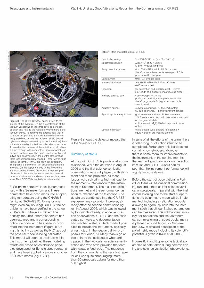
Figure 3: The CRIRES vessel open: a view to the interior of the cyrostat. On the circumference of the vacuum vessel two of the three cryo-coolers can be seen and next to the red safety valve there is the vacuum pump. To achieve the stability goal the in-strument support and the radiation shield are ther-mally stabilised. Inside the radiation shield (round cylindrical shape, covered by ‘super-insulation’) there is the separate light shield (complex shiny structure). To avoid radiation leaks at the shield level, all cables are fed through with connectors, some of which can be seen on the photo. The optics itself is configured in two sub-assemblies. In the centre of the image there is the trapezoidally shaped ‘Three-Mirror-Anas-tigmat’ assembly (TMA), the main spectrograph. The grating is below the TMA structure and hence invisible. On the upper left side to the TMA there is the assembly holding pre-optics and prism pre-disperser. In the state the instrument is shown, all detectors, all sensors and motors are easily acces-sible. Thus CRIRES is relatively easy to maintain.
Telescopes and Instrumentation Käufl H. U. et al., Good Vibrations: Report from the Commissioning of CRIRES
Spectral coverage
Spectral resolution
Array detector mosaic
Dark current
Infrared slit viewer
Precision
Intrinsic stability goal
Adaptive optics
Spectro-polarimetry in lines
Cryogenic system
l ~ 950–5 300 nm (n ~ 56–315 Thz)
l/Δl ≈105 or Δv ≈ 3km/s (2 pixel Nyquist sampling)
4 × 1024 × 512 Aladdin III InSb mosaic,therefore instantaneous l-coverage > 2.0 %pixel scale 0.1? per pixel
0.05–0.1 e–/s per pixel
Aladdin III InSb with J, H and K-filters0.05 arcsec/pixel
for calibration and stability (goal) ~ 75m/si.e. 1/20th of a pixel or 5 mas tracking error
spectrograph << 75m/spreference in design was given to stabilitytherefore gas cells for high-precision radial velocity work
curvature sensing ESO-MACAO system60 sub-apertures, R-band wavefront sensor
goal to measure all four Stokes parameterl/4 Fresnel rhomb and l/2 plate in rotary mounts on the gas-cell slide cold kinematic MgF2 Wollaston prism in fore-optics
three closed-cycle coolers to reach 65 Kliquid Nitrogen pre-cooling system
Table 1: Main characteristics of CRIRES.
Pho
to: J
.-L.
Liz
on,
ES
O

35The Messenger 126 – December 2006
Science with CRIRES To have an optimum match between the scientific requirements and the Procrus-tes’ bed of technical constraints, a sec-ond scientific workshop was organised in November 2003 at ESO on “High Reso-lution Infrared Spectroscopy in Astron-omy” (Käufl et al. 2005). This workshop confirmed, that CRIRES is a long awaited unique observing facility, to which there will be a great demand in astronomy ranging from the inner Solar System to
Figure 5: CRIRES spectrograph detector assembly: The four Aladdin III detectors comprising the spec-trograph focal plane in their mount. The detectors have been taken out of their original sockets and hybridised to custom-made ceramic boards. In this way the requirement of very high mechanical and thermal stability as well as a minimal gap between detectors (nominally 283 pixel) was achieved. While the complete assembly can be adjusted relative to the TMA-housing, the individual detectors – for rea-sons of stability – have not been mounted with means for relative adjustment. From each of the four
1k × 1k arrays the best two 512 × 512 quadrants are being used. Thus the two central detectors are being read perpendicularly to the dispersion direc-tion while the devices left and right are read paral- lel to the dispersion direction. The effective useful area of the detector is ~ 5 000 × 512 pixel which cor-responds to an instantaneous coverage of a wave-length interval ~ 2.5 % of the central wavelength. As the detector focus can only be changed by man-ual intervention it is intrinsically quite stable, but it required an iterative process of thermal cycles for final alignment.
2188 2190 2192 2194 2196Wavelength (nm)
10
100
1000
Flux
(AD
U/p
ix)
Figure 4: ThAr sample spectrum: The extracted spectrum corresponds to one of the four detectors and is a representative example of the line den-sity. While the frequencies of the strongest lines have been measured with high precision in collaboration with NIST (F. Kerber, catalogue in prep-aration) the weaker lines will be ca-talogued with CRIRES and ways to measure their frequencies equally pre-cisely have to be explored.
20 10 0 –10 –20–20
–10
0
10
20
30
Arc
seco
nds
–2 –1 0 1 2
–2
0
1
2
ArcsecondsReference Pos. R. A. 18h14m39s.50 DEC –17˚52�2� (2000)
–1
Figure 6: CRIRES as an adaptive optics pseudo imager: This K-band image was obtained using the MACAO adaptive optics system and the CRIRES slit-viewer camera. At the centre is the galactic H ii region W33A (North is up, East to the right). To ac-commodate the very high dynamic range of this image a logarithmic intensity scale has been chosen. The insert shows the centre region with a different scale. It is remarkable to see in this image a dark lane South of the main source which is aligned with Maser spots reported in literature (data courtesy R. Siebenmorgen, K. Menten and the CRIRES sci-ence verification team). CRIRES is of course not meant to be a competitor to dedicated AO-imagers especially as the spatial sampling is only 0.05? per pixel. However users can expect, if required, this kind of quality imaging to record the exact location of the spectrograph entrance slit.
damped Lyman-a absorption systems. Correspondingly diverse were the many proposals received for science verifi-cation, and even new projects have emerged, which were not on the horizon at the time of the workshop in Garching.
While the frequency range accessible to CRIRES contains many atomic transi-tions, which match or complement opti-cal observations very well, the really new features to be observed with CRIRES are molecular rotational-vibrational tran-
sitions. As many of these lines are seen in absorption while intrinsically quite nar-row, the spectral resolution is an absolute must. CRIRES has a resolution nearly three times that of the next competing in-strument and thus in many cases will be three times more sensitive. Thus many new discoveries can be expected. It should be noted, however, that any infra-red observer nolens volens does high-resolution infrared spectroscopy as the infrared active trace-gases of our atmos-phere provide for an extremely high-res-olution quasi statistical narrow-band filter (Figure 8). A rigorous calibration of tellu-ric effects is often only possible if the tel-luric lines are resolved, irrespective of the resolution required for the astrophysical object under study.
Pho
to: R
. Dor
n, E
SO

36 The Messenger 126 – December 2006
Figure 7: Sample spectrum from W33A: The sample spectrum is taken in the centre of the CO-funda-mental band. It corresponds to a fraction of one of the four detectors. The solid line is the spectrum from the compact H ii region and the gray line is a reference star to illustrate the telluric absorption. The W33A spectrum has been corrected as well as possible for the telluric absorption. The parabolic shape of the continuum from W33A is due to CO ice. As can be seen from the standard star, our local at-mosphere also contains CO, however a bit Doppler-shifted. The local telluric CO is saturated, so that a correction in the centre of the lines is not possible. To be able to get good and useful data, i.e. data which can be calibrated, the CRIRES exposure time calculator has a tool to predict the telluric absorp-tion taking into account the exact circumstances of
Telescopes and Instrumentation Käufl H. U. et al., Good Vibrations: Report from the Commissioning of CRIRES
Figure 8: Sample spectrum of an active galaxy: The top spectrum shows a coronal line observed with CRIRES during commissioning originating from eight times ionised Silicon at 3 942 nm. This line has an intrinsic width of 54 km/s. One may wonder what could be the ‘added value’ of such an ob-servation with a resolution of 1.5 km/s per pixel. The answer comes from looking at the raw data in the bottom figure, which shows the interfering telluric absorption spectrum. The Si ix line falls into a band of quite narrow telluric molecular absorption features. Only when resolving the telluric lines is it possible to correct for them. In other words, when observing this particular line with ten times lower resolution one would get both the equivalent width and the centre of gravity and thus the redshift wrong.
Figure 9: The happy commissioning team – at least most of them – shortly after first light in the VLT control room.
4 605 4 610 4 615 4 620 4 625 4 630Wavelength (nm)
0.0
0.2
0.4
0.6
0.8
1.0
1.2
F λ (R
elat
ive
flux)
3 925 3 930 3 935 3 940 3 945Wavelength (nm)
0.6
0.8
1.0
1.2
1.4
1.6
1.8
−1200 −1000 −800 −600 −400 −200 0 200Velocity (km/s)
[Si IX]
F λ (R
elat
ive
flux)
Circinus Galaxy[Si IX] FWHM: 54 km/s
3 925 3 930 3 935 3 940 3 945Wavelength (nm)
0
10
20
30
40
S/N
Conclusion and outlook
With CRIRES the ESO VLT first-genera-tion instrumentation plan has been com-pleted. CRIRES fills a large gap in the parameter map. It complements space astronomy very well, because high-reso-lution observations from the ground complement satellite observatories such as HST, Spitzer or the planned JWST. While CRIRES was built at ESO, the de-tector technology has progressed, so that a speedy detector upgrade is being investigated. This, together with other measures, will ensure significant further improvements of performance.
CRIRES will also be very valuable to as-sess and prepare the science case for a similar instrument for the European Ex-tremely Large Telescope project, which is presently taking its first steps.
Acknowledgements
Special thanks go to all colleagues on both sides of the Atlantic contributing to our project. Hans Ulrich Käufl feels particularly indebted to all colleagues and their families sometimes enduring a long string of quite extended missions to Paranal.
References
D’Odorico S., Moorwood A. F. M. and Beckers J. 1991, Journal of Optics 22, 85Käufl H. U. et al. 2003, SPIE proc. 4843, 223Käufl H. U. et al. 2004, SPIE proc. 5492, 1218Käufl H. U. et al. 2006, The Messenger 124, 2Käufl H. U., Siebenmorgen R. and Moorwood A. F. M. 2005, proceedings of the ESO Workshop
on “High Resolution Infrared Spectroscopy in Astronomy”, Springer-Verlag Berlin/Heidelberg
Ulrich M. H., proceedings of the ESO Workshop on “High Resolution Spectroscopy with the VLT”,
1992
the observations. For this sample spectrum, the Doppler shift is approximately 50 km/s. This needs to be compared with the orbital component of the Earth, i.e. the orbital velocity projected on the line of sight to the target which can be as much as +/-30 km/s. In that sense the exact timing of obser-vations matters, and must be part of the planning process when preparing a proposal or observing blocks from P2PP. The CO spectrum will provide for new and extremely detailed constraints on the con-ditions of the molecular cloud surrounding this H ii region (data courtesy R. Siebenmorgen, K. Menten and the CRIRES science verification team). CO, by the way, is the most abundant molecule in the Universe, which can be regularly observed (i.e. it emits dipole radiation).