gprs data logger - myqnapcloudmicrodatafi.myqnapcloud.com/ajurit/legato/gs828-h/manual/gs828… ·...
TRANSCRIPT

GPRS Data Logger GS828H Technical Guide
~ 1 ~
GPRS Data Logger Technical Guide GS828H, H2, HX [Version 6]
Standard GPRS Data Logger
GS828H (AC/DC Power Version)
GS828L (Low Power Version)
Temperature & Humidity GPRS Data Logger
GS828‐H2 / HX (AC/DC Power Version)
GS828‐L2 (Low Power Version)
Revision 110108 [V16C]
GPRS Data Logger GS828H Technical Guide
~ 2 ~
Contents
1. Overview................................................................................................................................................. 3
2. Features [GS828H] .................................................................................................................................. 4
3. Additional Features [GS828‐H2] ............................................................................................................ 4
4. Extended Features [GS828‐HX] .............................................................................................................. 4
5. Safety ...................................................................................................................................................... 5
6. Specification ........................................................................................................................................... 5
7. Wireless Module .................................................................................................................................... 5
8. Panel ....................................................................................................................................................... 6
9. Power Input ............................................................................................................................................ 7
10. Input Output Schematics ....................................................................................................................... 8
11. Temperature & Humidity Sensors ....................................................................................................... 11
12. Connecting Sensors/Transducers & Calibration .................................................................................. 12
13. PC Connection ...................................................................................................................................... 14
14. SIM Card Installation [GS828H, GS828‐H2] ......................................................................................... 14
15. Power Up .............................................................................................................................................. 15
16. Setup ..................................................................................................................................................... 16
17. Remote Configuration .......................................................................................................................... 17
18. Start Up ................................................................................................................................................. 18
19. Communication Protocol & Data Format ............................................................................................ 20
20. Attention on using SMS and GPRS DATA simultaneously .................................................................. 20
21. Enquiry Command ................................................................................................................................ 21
22. Setup Command ................................................................................................................................... 33
23. How GS828H response on alarm? ....................................................................................................... 44
24. Capturing, Logging & Upload ............................................................................................................... 45
25. RS485 Port ............................................................................................................................................ 46
26. UPD Testing Software .......................................................................................................................... 49
27. TCP and UDP Operation ....................................................................................................................... 52
28. Safety and Regulatory Notice .............................................................................................................. 54
29. Manufacturer’s Disclaimer Statement ................................................................................................ 55

GPRS Data Logger GS828H Technical Guide
~ 3 ~
1. Overview
GS828H/L GPRS Data Logger is a standalone RTU integrated with a 16 bit ARM MCU and low power consumption design. It’s built in digital processor, external interface, hardware watchdog, digital input, digital output, analog input and GPRS communication module. Wide operating temperature, electromagnetic resistant, anti‐vibrant and numerous interface protocols provide a highly reliable design for industrial application.
• GS828‐H is powered by 110/220VAC or 12VDC, and backup by internal rechargeable battery. Internal rechargeable battery maintains data and continuous operation when power loss.
• GS828‐H2 is enhanced version of GS828H with 2 x temperature sensors and 1 x humidity sensor bundled, and dedicatedly designed for temperature & humidity measurement.
• GS828‐L is powered by 12VDC, and featured with sleep mode allowing its continuous operation for more than 2 years with hi‐capacity battery, or solar panel. It resumes normal mode only when scheduled to upload data.
• GS828‐L2 is enhanced version of GS828L with 2 x temperature sensors and 1 x humidity sensor bundled, and dedicatedly designed for temperature & humidity measurement.
GS828H / GS828‐H2
GS828L / GS828‐L2

GPRS Data Logger GS828H Technical Guide
~ 4 ~
2. Features [GS828H]
• 6 x High Precision A/D Channels
• 10 x DI [Digital Input] or 6DP [Digital Pulse] Channels
• 4 x DO [Digital Output] Channels
• Power loss alert
• Programmable Upload Interval (5 seconds ~ one day)
• Programmable Logging Interval (1 minute ~ 60 minutes)
• Supports data upload via GPRS and SMS on schedule
• Supports data upload via GPRS and SMS triggered by alarm, or manual check
• Real Time Alarm Report via GSM SMS and/or GPRS Data
• Device setup, parameter check and status report via GSM SMS and/or GPRS Data
• Support local and remote setup via SMS / GPRS
• Programmable data capturing type, range, start point, threshold hi/low and pulse level
• 1 x RS232 Port for local setup or data transmission
• 1 x RS485 Port for device measurement supporting Industrial ModBus Protocol
• Support Dynamic Domain Name or Fixed IP
• Support UDP or TCP protocol data transmission
• 4MB Non‐volatile Memory storing data logged and setup parameters on power loss
• 35000 data records logged ‐ max. 120 days historical records when data is logged every 5 minutes
3. Additional Features [GS828‐H2]
• 6 x High Precision A/D Channels
• 10 x DI [Digital Input] or 4DP [Digital Pulse] Channels
• 4 x DO [Digital Output] Channels
2 x Temperature Sensor [1 x indoor type, 1 x submersible type]
1 x Humidity Sensor
4. Extended Features [GS828‐HX]
12 x High Precision A/D Channels
16 x DI [Digital Input] or 6DP [Digital Pulse] Channels
2 x Temperature Sensor [1 x indoor type, 1 x submersible type]
1 x Humidity Sensor
• 4 x DO [Digital Output] Channels

GPRS Data Logger GS828H Technical Guide
~ 5 ~
5. Safety
• Do not touch the antenna
• GSM 900MHz, 2W max. / GSM 1800MHz, 1W max.
• Not designed for medical equipment or aerospace application
6. Specification
GS828H, GS828‐H2, GS828‐HX
AC Power Input: Auto 90~260VAC
Internal Backup: Rechargeable Battery DC7.4V, 2Ah
DC Power Source: 10 ~ 24VDC, max. 3A
Enclosure: Metal Casing, 172 x 155 x 54 mm
GS828L, GS828‐L2
Power Input: DC 6.5 ~ 10V
Internal Battery: High Capacity Battery DC7.2V, 4Ah
Enclosure: Aluminum IP67, 280 x 199 x 90 mm
Current 500mA (SMS Send/Receive)
20mA (standby)
Peak Pulse Current < 1A
Operating Temp: ‐50˚C ~ +70˚C
Standby Temp: ‐50˚C ~ +80˚C
7. Wireless Module
It supports GSM and GPRS class 10.
GSM 850 E‐GSM 900 DCS 1800 PCS1900
Rx band (MHz) 869~894 925~960 1805~1880 1930~1990
Tx band (MHz) 824~849 880~915 1710~1785 1850~1910
Rx Sensitivity ‐109 dBm ‐109 dBm ‐108 dBm ‐108 dBm
Tx Sensitivity 33 dB 33 dB 30 dB 30dB
RF Rating 2W 2W 1W 1W
Loading Resistance 50 Ohm
GSM Quad: Siemens MC55i Quad Band [850/900/1800/1900]

GPRS Data Logger GS828H Technical Guide
~ 6 ~
8. Panel
Internal Layout [GS828‐H, GS828‐H2, GS828‐HX]
Front Panel
Back Panel

GPRS Data Logger GS828H Technical Guide
~ 7 ~
9. Power Input
9.1 AC Power Input
90~260V AC input can be connected to power socket as power source. 9.2 DC Power Input
10~24V DC input can be connected to POW and GND as power source.
AC Input and DC Input should NOT be connected at the same time.
9.3 Internal Rechargeable Battery
• Short the pins BAT‐1 and BAT‐2 to turn on the rechargeable battery
• When device is not in use, open the pins connection to save the power
of rechargeable battery
• When AC power is plugged and BAT pins are shorted, device is
powered by AC and internal battery is being charged.
• Charging will be automatically stopped when battery is full.
• When both AC and DC input are lost, device will be powered by internal battery.
+ _

GPRS Data Logger GS828H Technical Guide
~ 8 ~
10. Input Output Schematics
10.1 Analog Input
AD01 ‐ 04
Analog Channel AD01 ~ 04 AD05 ~ 16
Jumper J1 ~ J4 No Jumper
Short Open ‐‐
Input Type Current Voltage Current
Range DC 4~20mA DC 0 ~ 5V DC 4~20mA
Input Impedance R 250 Ω 20K Ω 250 Ω
10.2 Digital Input
IN01 – 04 [Programmable On/Off or Pulse Channel]
a) On/Off Channel
• Triggered Level > 20ms
• Input Resistance 1KΩ, 1/4W
• DC5~24V voltage or DC5~24mA current
b) Pulse Channel
• Pulse Frequency Measure > 20ms IN05 – 10
o Dry Contact o Input: Non‐power type
10.3 Relay Output
Max. Loading: DC24V @1A, AC220V @1A OUT 1 – 2
Jumper 1‐2 short: Normal Close Jumper 2‐3 short: Normal Open
OUT 3 – 4 No Jumper: Normal Open

GPRS Data Logger GS828H Technical Guide
~ 9 ~
Connection Example:
10.4 RS485 Port
• ModBus Protocol
• Support external sensors or measuring devices
10.5 Extended Input Output Channels
• Only available in model GS828‐HX

GPRS Data Logger GS828H Technical Guide
~ 10 ~
10.6 Temperature Sensor Input
• Bundled Temperature Sensor must be used
• This input should NOT be used as AD channels for other sensors
T_V1 max. 1 meter cable long T_V2 max. 100 meter cable long
10.7 Temperature & Humidity Sensor Input
• Bundled Temperature & Humidity Sensor must be used
• This input should NOT be used as AD channels for other sensors
TH_V1 max. 1 meter cable long TH_V3 max. 100 meter cable long
Color Code: T_V1 Red / Blue / Black T_V2 Red / Yellow / Black
Color Code: TH_V1 Brown / Blue / Black / Yellow TH_V3 Red / Green / Yellow / Black

GPRS Data Logger GS828H Technical Guide
~ 11 ~
11. Temperature & Humidity Sensors
Two Temperature Sensors and One Humidity Sensor are integrated with the device for environmental
monitoring [GS828‐H2, GS828‐HX].
a) Temperature Sensor is built in a waterproof steel housing for outdoor or submersible monitoring.
Temperature_1 = AD Channel 13
b) Temperature Sensor and Humidity Sensor are built in the same housing for indoor monitoring.
Humidity = AD Channel 00
Temperature_2 = AD Channel 14
First & Second Temperature Sensor
Model: DS18B20
Temperature Range: ‐50 ~ 125°C
Accuracy: 0.1°C
T_V1: max. 1 meter cable
T_V2: max. 100 meter cable
Temp_1 Sensor: AD Channel 13
Temp_2 Sensor: AD Channel 14
Humidity Sensor
Model: CHM‐01A
Humidity Range: 0 ~ 100%RH
Accuracy: ± 5%RH
TH_V1: max. 1 meter cable
TH_V3: max. 100 meter cable
Sensor: AD Channel 00

GPRS Data Logger GS828H Technical Guide
~ 12 ~
12. Connecting Sensors/Transducers & Calibration
• Sensor Output: Voltage Type Range: 0 ~ 5V DC Jumper: Open
• Sensor Output: Current Type Range: 4 ~ 20mA Jumper: Short
Make sure that the connection of sensor devices is followed according to its output type. Wrong
wiring may damage not only the sensor but also the data logger.
GPRS Data Logger GS828H Technical Guide
~ 13 ~
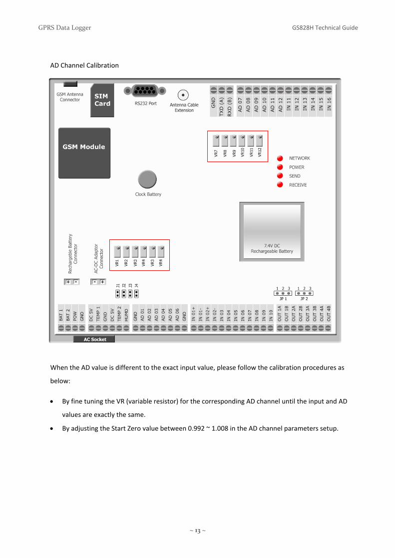
AD Channel Calibration
When the AD value is different to the exact input value, please follow the calibration procedures as
below:
• By fine tuning the VR (variable resistor) for the corresponding AD channel until the input and AD
values are exactly the same.
• By adjusting the Start Zero value between 0.992 ~ 1.008 in the AD channel parameters setup.

GPRS Data Logger GS828H Technical Guide
~ 14 ~
13. PC Connection
RS232 Port is available for PC connection running “DataLogger_Setup” Software locally:
• GS828 configuration setup
• GS828 data download
14. SIM Card Installation [GS828H, GS828‐H2]
1) Press the yellow button to release the SIM card caddy as shown below.
2) Insert the SIM card into caddy.
3) Make sure that the golden contact is facing down when inserting the SIM card caddy.

GPRS Data Logger GS828H Technical Guide
~ 15 ~
15. Power Up
Turn on the unit by either one of the following:
13.1) When AC power is used:
• Plug in the AC socket
• Enable the internal battery backup by short jumper BAT‐1 & 2
13.2) When DC power is used:
• Connect 10~24VDC power input pins POW, GND
LED Display:
1) Network GPRS Module Status
Always OFF Not Ready Flash @1 second Checking network connection Flash @3 seconds Network Connected & Ready
2) POW Power Source
ON AC Power is used OFF AC Power is lost, Internal Battery is used.
3) TXD Sending GPRS Data or GSM SMS
Flash (startup) Checking network connection Flash Sending Data
4) RXD Receiving GPRS Data or GSM SMS
Flash (startup) Checking network connection
Flash Receiving Data
• After GPRS network connection is lost for 2 minutes, RXD will flash for 5 minutes trying to
reconnect to GPRS network.
• If connection is still lost, TXD will be ON for 15 minutes.
• After 15 minutes, data logger will reset the GSM module and try to rebuild the GPRS connection.
+ _

GPRS Data Logger GS828H Technical Guide
~ 16 ~
16. Setup
GS828 GPRS Data Logger can be setup in four ways.
Before site installation, setup and test via RS232 port by PC software is highly recommended.

GPRS Data Logger GS828H Technical Guide
~ 17 ~
17. Remote Configuration
17.1 Command via GPRS DATA
• Most commands can be delivered via GPRS Data, except those configuring the GPRS
network properties.
• Command in remote configuration should have @888 header in order to comply with UDP
protocol format.
Example:
Mode: GPRS DATA [TCP Protocol], GSM SMS, RS232 Port
Status Check
Command: @888999999#STATUS#
17.2 Command via GSM SMS
• Most commands can be implemented via SMS by mobile phone or GSM Modem remotely.
17.3 Command via RS232
• All commands can be implemented via RS232 but only possible on site.
Note: GS828L is a device designed for low power operation and always in standby mode. All
command will be processed only when GS828L resumes normal mode.
GS828L is preset to upload data at 08:00 every day and remains in normal mode for another 1
minute after data upload. During this period, command @888888888#MO:2# is used to turn
the device into normal mode. The device can then be setup in other parameters configuration.
After the setup, command @888888888#MO:1# is needed to turn the device into sleep mode
again.

GPRS Data Logger GS828H Technical Guide
~ 18 ~
18. Start Up
18.1) Quick Startup Procedure:
1. Insert the SIM Card
2. Turn on the unit by plug in the AC power cord
3. Connect BAT‐1&2 pins to enable the internal battery backup
18.2) Power On
Signal LED
OFF>ON GPRS network registration success
OFF GPRS network registration fail
a) GPRS module defective
b) SIM card defective
c) Network Unavailable
d) GS828 Device Setup not configured properly
Note: GPRS network registration takes about 1 ~ 1.5 minutes
During the first time start up, GPRS registration usually fails because of incomplete
configuration of GPRS network properties.

GPRS Data Logger GS828H Technical Guide
~ 19 ~
18.3) GPRS Data Logger Network Setup
Use mobile phone sending SMS command to setup the following parameters.
Use PC and “Datalogger_Setup” Software to setup the following parameters
1) When public fixed IP is available, please follow the steps below in sequence.
• GPRS Access Point (APN)
• Server IP Port
• Server IP Address
• Domain Name is left blank
2) When no public fixed IP is available, dynamic domain name is needed.
• GPRS Access Point (APN)
• Server IP Port
• Server IP Address is left blank
• Domain Name (please visit www.dyndns.com/support/kb/what_is_dns.html)
After GPRS network registration, the green GPRS LED on “DataLogger_Setup Software” screen
indicates the proper network access.
18.4) Server PC Network Setup
1) When public fixed IP is available, please follow the steps below.
• Configure public fixed IP address in Server PC if it is connected to Internet directly
• Configure router WAN IP as public fixed IP address and port forward to server local LAN IP
if server PC is connected to Internet via router
• Open the Server port in firewall and router
2) When no public fixed IP is available, dynamic domain name is needed.
• Use DDNS service e.g. http://www.dyndns.com, and apply for a domain name
• Router port must be forwarded to server local LAN IP
• Use the DNS tool to map the domain name and server local LAN IP address
• Open the Server port in firewall and router
.

GPRS Data Logger GS828H Technical Guide
~ 20 ~
19. Communication Protocol & Data Format
Header Description:
STA Real Time Data
STB Packet Data
STC Parameters Check
STD Historical Data
STS Acknowledge Message to Setup Command
20. Attention on using SMS and GPRS DATA simultaneously
When GPRS DATA data upload is unsuccessful, GS828 will redial and try to connect to GPRS network
for re‐uploading the data.
During the redial interval or re‐uploading the data via GPRS DATA, any SMS command will be lost and
schedule SMS data upload will also be dismissed.
Therefore, when the GPRS DATA data upload interval is short, it is recommended to select a longer
SMS upload interval and vice versa.
It normally takes about 45~60 seconds to complete an incoming SMS command or outgoing SMS data
upload

GPRS Data Logger GS828H Technical Guide
~ 21 ~
21. Enquiry Command
A) Real Time Status Check
Mode: GPRS Data, GSM SMS
Command: 999999#STATUS#
GPRS Reply Message: Live Data
#STA:000000,000;L:310;TM:090516195102;D:1;T:01;C:25;A00:0.166;A01:00000;A02:0.578;A03:00
000;A04:00000;A05:00000;A06:00000;A07:00000;A08:00000;A09:00000;A10:00000;A11:00000;A1
2:00000;A13:31.00;A14:30.93;P01:00000000;P02:00000000;P03:00000000;P04:00000000;P05:000
00000;P06:00000000;K01:13333330000000000;O01:0000;8F#
SMS Reply Message: Live Data
#STA:000000,000;L:310;TM:03/04/2009,09:34;D:1;T:01;C:25;A00:0.166;A01:00000;A02:0.578;A03:
00000;A04:00000;A05:00000;A06:00000;A07:00000;A08:00000;A09:00000;A10:00000;A11:00000;
A12:00000;A13:31.00;A14:30.93;P01:00000000;P02:00000000;P03:00000000;P04:00000000;P05:0
0000000;P06:00000000;K01:13333330000000000;O01:0000;8F#
P.S.: Max. 160 characters in each SMS message, second SMS messages with header STA: will be
sent when data is more than 160 characters.
#STA: 000000,000 STA Header: Live Data
000000 Station ID
000 Hardware Version
L:310 Number of characters in packet from “S” to the last “;” inclusive
TM:0702011200 Current Date Time of GPRS Data Logger (yymmddhhmm)
D:1 Logging Interval
T: 01 Number of records in each data packet
D Data Logging Interval
5 1 minute
1 5 minutes
2 15 minutes
3 30 minutes
4 60 minutes

GPRS Data Logger GS828H Technical Guide
~ 22 ~
C: 08 Counter of packets uploaded
It is used to check any loss of data packet.
It should be increasing and reset to 00 when it is over 99.
A01:00000 Value captured on AD Channel 1 [A02, A03… A12 are the same]
A00: Humidity
A13: Temperature 1
A14: Temperature 2
P01:01234212 Accumulated Pulses captured [P02, P03… P06 are the same]
It is accumulated, and reset to 0 when it is over 99999999
K:xyyyyyyzzzzzzzz First digit x – status of power source
1: AC power input is ON
0: AC power input is OFF (now powered by battery)
2nd ~ 7th digit yyyyyy – status of Digital Channel 01 ~ 06
3: Configured as Pulse Channel
1: Configured as On/Off Channel, Alarm Input is closed
0: Configured as On/Off Channel, Alarm Input is open
8th ~17th digits zzzzzzzzzz – status of Digital Channel 07 ~ 16
1: Configured as On/Off Channel, Alarm Input is closed
0: Configured as On/Off Channel, Alarm Input is open
O01:0000 indicates the status of Digital Output [Relay Output]
1 Close
0 Open
8F Parity Check
# End Symbol

GPRS Data Logger GS828H Technical Guide
~ 23 ~
B) Automatic schedule data upload
Mode: GPRS Data, GSM SMS
Command: upload is on schedule, and no command is necessary
Reply Message: upload is in packet data
#STB:000000,000;L:642;TM:0906121535;D:1;T:03;C:17;
A00:00000|00000|00000;A01:‐0.24|‐0.24|‐0.24;A02:‐0.24|‐0.24|‐0.24;A03:‐0.24|‐0.24|‐
0.24;A04:‐0.24|‐0.24|‐0.24;A05:‐0.24|‐0.24|‐0.24;A06:‐0.24|‐0.24|‐0.24;A07:‐0.24|‐0.24|‐
0.25;A08:‐0.25|‐0.25|‐0.24;A09:‐0.24|‐0.24|‐0.25;A10:‐0.24|‐0.24|‐0.24;A11:‐0.24|‐0.24|‐0.24;
A12:‐0.24|‐0.24|‐0.24;A13:‐0.06|‐0.06|‐0.06;A14:‐0.06|‐0.06|‐0.06;
P01:00000016|00000016|00000016;P02:00000006|00000006|00000006;P03:00000005|0000000
5|00000005;P04:00000009|00000009|00000009;P05:00000006|00000006|00000006;P06:00000
006|00000006|00000006;
K01:13333330000000000|13333330000000000|13333330000000000;O01:0000|0000|0000;19#
#STB: 000000,000 STB Header: Packet Data
000000 Station ID
000 Hardware Version
L:642 Number of characters in packet from “S” to the last “;” inclusive
TM: 0906121535 Starting Date Time of Data Packet (yymmddhhmm)
D:1 Logging Interval
T: 03 Number of records in the data packet
C: 08 Counter of packets uploaded
| Data record separator
Each data record interval will be defined by parameter D
XX Parity Check
# End Symbol
In this example: Upload Interval is 15 minutes
Logging Interval is 5 minutes
Records at 15:35, 15:40, 15:45 are packed into the data
D Data Logging Interval
5 1 minute 1 5 minutes
2 15 minutes
3 30 minutes
4 60 minutes

GPRS Data Logger GS828H Technical Guide
~ 24 ~
Another Example: Upload Interval is 30 minutes
Logging Interval is 15 minutes
D: 2 Logging Interval is 15 minutes
T:02 Number of records is 2 in this data packet
Records at 15:30, 15:45 are packed into the data
#STB:000000,000;L:475;TM:0906121530;D:2;T:02;C:17;
A00:00000|00000;A01:‐0.24|‐0.24;A02:‐0.24|‐0.24;A03:‐0.24|‐0.24;A04:‐0.24|‐0.24;A05:‐0.24|‐
0.24;A06:‐0.24|‐0.24;A07:‐0.24|‐0.24;A08:‐0.25|‐0.25;A09:‐0.24|‐0.24;A10:‐0.24|‐0.24;A11:‐
0.24|‐0.24;A12:‐0.24|‐0.24;A13:‐0.06|‐0.06;A14:‐0.06|‐0.06;
P01:00000016|00000016;P02:00000006|00000006;P03:00000005|00000005;P04:00000009|0000
0009;P05:00000006|00000006;P06:00000006|00000006;
K01:13333330000000000|13333330000000000;O01:0000|0000;19#

GPRS Data Logger GS828H Technical Guide
~ 25 ~
C) Historical Data Manual Retrieval
Mode: GPRS Data, RS232 Port [SMS is not supported]
Command: 999999#REDEEM090512161004#
REDEEM historical data retrieval
0712281645 starting date time on 2009‐05‐12 at 16:45
04 number of records to be retrieved each packet
Reply Message:
#STD:000000,000;L:809;TM:0905161610;D:1;T:04;C:18;
A00:00041|00000|00000|00000;A01:‐0.24|‐0.24|‐0.24|‐0.24;A02:‐0.24|‐0.24|‐0.24|‐0.24;
A03:‐0.24|‐0.24|‐0.24|‐0.24;A04:‐0.24|‐0.24|‐0.24|‐0.24;A05:‐0.24|‐0.24|‐0.24|‐0.24;
A06:‐0.24|‐0.24|‐0.24|‐0.24;A07:‐0.24|‐0.24|‐0.24|‐0.24;A08:‐0.24|‐0.24|‐0.24|‐0.24;
A09:‐0.24|‐0.24|‐0.24|‐0.24;A10:‐0.24|‐0.24|‐0.24|‐0.24;A11:‐0.24|‐0.24|‐0.24|‐0.24;
A12:‐0.24|‐0.24|‐0.24|‐0.24;A13:33.06|32.00|33.18|33.18;A14:31.68|30.87|31.62|31.87;
P01:00000000|00000000|00000000|00000000;P02:00000000|00000000|00000000|00000000;
P03:00000000|00000000|00000000|00000000;P04:00000000|00000000|00000000|00000000;
P05:00000000|00000000|00000000|00000000;P06:00000000|00000000|00000000|00000000;
K01:13333330000000000|13333330000000000|13333330000000000|13333330000000000;
O01:0000|0000|0000|0000;48#
STD:000000,000 STD Historical Data Packet
000000 Station ID
000 Hardware Version
L:809 Number of characters in packet from “S” to the last “;” inclusive
TM: 0905161610 Starting Date Time of Data Packet (yymmddhhmm)
D:1 Logging Interval
T:04 Number of records in the data packet
4 records at 16:10, 16:15, 16:20, 16:25
are in the data packet
C:07 Counter of packets uploaded
It is used to check any loss of data packet.
It should be increasing and reset to 00 when it is over 99.
D Data Logging Interval
5 1 minute 1 5 minutes
2 15 minutes
3 30 minutes
4 60 minutes

GPRS Data Logger GS828H Technical Guide
~ 26 ~
AD Channel record data:
A01:3.323|3.323|3.323|3.323
Pulse Channel record data:
P01: 00087032|00087679|0008790|0008790
Digital Input On/Off record data:
K: 13333330000000000|13333330000000000|13333330000000000|13333330000000000
| Data record separator
48 Parity Check
# End Symbol
GPRS Data & RS232
Max. number of records to be retrieved each time: 99 records
Max. number of records each data packet: 30 records
When more than 30 records are retrieved, more than one data packets will be sent .
For example, 46 records are to be retrieved from the Data Logger.
2 packets will be delivered.
1st packet: 30 records
2nd packet: 16 records
GSM SMS
Only one record can be retrieved each time via SMS owing to the limitation of SMS text length.
Storage Period:
1) Internal Memory: 1MB
2) Records can be kept in the device at about 90 days when logging interval is at 15 minutes.
3) The storage period can be longer than 90 days when logging interval is set at 60 min.
4) When there is no record data on the selected date, packet data will only include characters “9”.

GPRS Data Logger GS828H Technical Guide
~ 27 ~
D) System Parameters Check
Mode: GPRS DATA, GSM SMS
Command: 999999#CHEACK1#
Reply Message:
#STC1:000000,000;L:227;TM:0905161954;PS:999999,888888;SA:1;SD:02,0,1;CP:13750782917,0;AP
1:13143882308;AP2:;DR:001;ID:CMNET;IA:0;IP:;IY:abc.mabc.com;IH:6060;IT:0120;IR:0888;IU:1;ER:
000; OUT:1:0000;OUT:2:0000;OUT:3:0000;OUT:4:0000;PL:850/1900XH:29;3C#
#STC1:000000,000 Header, Station ID, Hardware Version
L:227 Number of characters in packet from “S” to the last “;” inclusive
TM: 0905161954 Current date time of GPRS Data Logger (yymmddhhmm)
PS:999999,888888 Check Password, Setup Password
SA:2 Data Logging Interval
SD:xx,y,z GPRS Upload Interval, Data Format, Number of times data is uploaded
xx: Upload Interval
y=0: Live Data y=1: Packet Data z= number of re‐upload
When upload interval is 24 hours, data is uploaded every day at 8:00am.
CP:yyyyyyyyyyy,X Control Center Phone Number (receiving SMS), Upload Interval via SMS
SA Data Logging Interval
0 No Save
5 1 minute 1 5 minutes
2 15 minutes
3 30 minutes
4 60 minutes
xx = 00 No Upload 05 15 minutes
12 5 seconds 06 30 minutes
13 15 seconds 07 1 hour
01 30 seconds 08 2 hours
02 1 minute 09 6 hours
03 2 minutes 10 12 hours
04 5 minutes 11 24 hours
X = 0 No Upload 5 1 hour
1 1 minute 6 2 hours
2 5 minutes 7 6 hours
3 15 minutes 8 12 hours
4 30 minutes 9 24 hours

GPRS Data Logger GS828H Technical Guide
~ 28 ~
AP1:xxxxxxxxxxx Alarm Phone Number 1
AP2 is the same for alarm phone number 2
DR:001 ModBus Address
ID:CMNET GPRS APN (Access Point Network)
IA:1 Server Location 1: Fixed IP 0: Domain Name
IP: 210.3.32.70 Server Fixed IP Address
IY:abc.net Domain Name
IH:5600 Server Port
IT: Acknowledge Interval
IR: Redial Period
IU:1 Connection Protocol 1: UDP Protocol 0: TCP Protocol
ER:000 GPRS Module Status
First Digit 0: Module Normal 1: Module Defect
Second Digit 0: SIM Card Normal 1: SIM Card Defect
Third Digit 0: GPRS Connection Normal 1: Connection Error
OUT:1:xxxx Time Lapse of Relay 1 ON triggered by Alarm (in seconds)
OUT:2, OUT:3, OUT:4 same for Relay 2, 3, 4
PL:850/1900XH GSM Band Selected
0 mono‐band mode 850 MHz
1 mono‐band mode 900 extended MHz (900E)
2 mono‐band mode 1800 MHz
3 mono‐band mode 1900 MHz
4 dual‐band mode 850/1900 MHz
5 dual‐band mode 900E (extended) / 1800 MHz
6 dual‐band mode 900E (extended) / 1900 MHz
XH:29 Network Signal Strength
3C Parity Check
# End Symbol
E) Input Channel Parameters Check

GPRS Data Logger GS828H Technical Guide
~ 29 ~
Mode: GPRS DATA, GSM SMS
Command: 999999#CHEACK2#
Reply Message:
#STC2:000000,000;L:556;AD00:170.0,0.000,0.000,1,170.0,0.000;AD01:1.000,0.000,1.000,1,1.000,0.
000;AD02:1.000,0.000,1.000,1,1.000,0.000;AD03:1.000,0.000,1.000,1,1.000,0.000;AD04:1.000,0.00
0,1.000,1,1.000,0.000;AD05:1.000,0.000,1.000,1,1.000,0.000;AD06:1.000,0.000,1.000,1,1.000,0.00
0;AD07:1.000,0.000,1.000,1,1.000,0.000;AD08:1.000,0.000,1.000,1,1.000,0.000;AD09:1.000,0.000,
1.000,1,1.000,0.000;AD10:1.000,0.000,1.000,1,1.000,0.000;AD11:1.000,0.000,1.000,1,1.000,0.000;
AD12:1.000,0.000,1.000,1,1.000,0.000;AD13:1,100.0,0.000;AD14:1,100.0,0.000;PA:01111110000;C
5#
#STC2:000000,000 Header, Station ID, Hardware Version
L:556 Number of characters in packet from “S” to the last “;” inclusive
AD01: xxxxx,yyyyy,zzzzz,m,aaaaa,bbbbb
Analog Digital Channel 01
Measuring Upper Limit xxxxx
Measuring Lower Limit yyyyy
Start zero value zzzzz
m 0: disable channel
1: enable channel
2: enable channel and Hi/Lo Alert
Hi Alert Value aaaaa
Lo Alert Value bbbbb
When AD input source is 4~20mA current type and input resistance is configured as 250 ohm, the
start zero should be 1.000 (0.004A x 250Ω = 1V).
AD02~12 same as AD01

GPRS Data Logger GS828H Technical Guide
~ 30 ~
AD00: Analog Digital Channel 00 = Humidity Sensor
170.0,0.000,0.000,x,150.0,6.000
Measuring Upper Limit 170.0
Measuring Lower Limit 0.000
Start zero value 0.000
m 0: disable channel
1: enable channel
2: enable channel and Hi/Lo Alert
Hi Alert Value 150.0
Lo Alert Value 6.000
AD13: Temperature Sensor 1
1,120.0,‐30.0
m 0: disable channel
1: enable channel
2: enable channel and Hi/Lo Alert
Hi Alert Value 120.0 °C
Lo Alert Value ‐30.0 °C
AD14: Temperature Sensor 2
AD13 & AD14 are integrated with digital temperature sensor DS18B20. Measuring range, upper
and lower limits are fixed as below.
Measuring Upper Limit 125.0
Measuring Lower Limit ‐50.0

GPRS Data Logger GS828H Technical Guide
~ 31 ~
PA: xyyyyyymmmm
1st digit x: Setting of Power Source Alert
0 = No Alarm
1 = AC Power Resume Alarm
2 = AC Power Loss Alarm
3 = AC Power Resume/Loss Alarm
2nd~7th digit yyyyyy Setting of Channel IN01 ~ IN06
0 = Channel Disable
1 = Pulse Channel Enable
2 = NO ‐ Close Triggered Alarm
3 = NC ‐ Open Triggered Alarm
4 = Change State Triggered Alarm
8th~11 digit mmmm Setting of Channel IN07~ IN10
0 = Channel Disable
2 = NO‐ Close Triggered Alarm
3 = NC ‐ Open Triggered Alarm
4 = Change State Triggered Alarm
IN11 ~ IN16 No alarm function
C5 Parity Check
# End Symbol

GPRS Data Logger GS828H Technical Guide
~ 32 ~
F) Output Channel Parameters Check
Mode: GPRS DATA, GSM SMS
Command: 999999#CHEACK3#
Reply Message:
#STC3:000000,000;L:153;COUT1:YYYYYYYYYYYYYYYYYYYYYYYYYY;COUT2:00000000000000000000000000;COUT3:00000000000000000000000000;COUT4:00000000000000000000000000;F5#
#STC3:000000,000 Header, Station ID, Hardware Version
L:153 Number of characters in packet from “S” to the last “;” inclusive
COUT1: HMMMMMMMMMMMMEEPNNNNNNNNNN
1: Turn On Relay Output 1
0: No Relay Output Control
COUT2: 1: Turn On Relay Output 2
0: No Relay Output Control
Same as COUT3 & COUNT4
H: 1st digit AD00 Humidity Sensor
M: 2nd~13th digits AD01~AD12 Analog Input
E: 14th~15th digits AD13~AD14 Temperature Sensor 1 & 2
P: 16th digit Power Source
N: 17th~26th digits IN01~IN10 Digital Input
F5 Parity Check
# End Symbol
G) Version Check
Mode: GPRS Data, GSM SMS
Command: 999999#CHEACKVR%
Reply Message: SDH828H VA‐1 05/26/2009#

GPRS Data Logger GS828H Technical Guide
~ 33 ~
22. Setup Command
a) Setup Command Reply Message
Success Reply: #STS:000010, Set Success#
Failure Reply: #STS:000010, Set Fail#
b) Device ID
Mode: GPRS DATA, GSM SMS, RS232
Command: 888888#ST:xxxxxx# (Default: 000000, Range:00 0000 ~ 999999)
Example: 888888#ST:000010#
c) Password
Mode: GPRS DATA, GSM SMS, RS232
Command: 888888#PS:xxxxxx,yyyyyy#
xxxxxx Inquiry Password (Default: 999999, Range: any six digits)
yyyyyy Setup Password (Default: 888888, Range: any six digits)
Example: 888888#PS:333333,777777#
d) System Time
Mode: GPRS DATA, GSM SMS, RS232
Command: 888888#TM:yymmddhhnn#
Example: 888888#TM:0712230615#
e) Configuration Reset
Mode: GPRS DATA, GSM SMS, RS232
Command: 888888#RESET#
All parameters (except GSM band & password) will be restored to factory
Success Reply: Initialized success!
f) Power Mode [GS828L]
Mode: GPRS DATA, GSM SMS, RS232
Command: 888888#MO:X# (Default: 2)
X: 1: Sleep (Low Power) Mode always ‐ no response to command
2: Normal Operation Mode ‐ response to command
3: Sleep Mode after 7 minutes normal mode

GPRS Data Logger GS828H Technical Guide
~ 34 ~
g) Set GPRS Network Access Point [APN]
Mode: GSM SMS, RS232
Command: 888888#ID:XXXXXXXX!#
XXXXXX: Access Point [max. 29 characters]
!: End Symbol
Example: 888888#ID:vodafone.internet!#
h) Set Server IP Address
Mode: GSM SMS, RS232 Port
Command: 888888#IP:xxx.xxx.xxx.xxx!#
xxx.xxx.xxx.xxx: IP Address
!: End Symbol
Example: 888888#IP:123.45.56.122!#
i) Set Server Port Number
Mode: GSM SMS, RS232 Port
Command: 888888#IH:xxxxx# (Default: 6000)
xxxxx: Port Number
Example: 888888#IH:6050#
Note: After setting up the port number, IP Address must be setup to save these two
parameters.
j) Set Domain Name (DDNS)
Mode: GSM SMS, RS232 Port
Command: 888888#IY:mmmmm!#
mmmmm: Domain Name
!: End Symbol
Example: 888888#IY:dyndns.com!#
k) Set Protocol
Mode: GSM SMS, RS232 Port
Command: 888888#IU:X# (Default: 0)
X: 0: TCP 1:UDP
Example: 888888#IU:0#

GPRS Data Logger GS828H Technical Guide
~ 35 ~
l) Set ModBus Protocol Address
Mode: GSM SMS, RS232 Port
Command: 888888#DR:XXX# (Default: 001)
Example: 888888#DR:226#
m) Setup GSM Band
Mode: GSM SMS, RS232 Port
Command: 888888#PL:X# (Default: 5)
X: 0 mono‐band mode 850 MHz
1 mono‐band mode 900 extended MHz (900E)
2 mono‐band mode 1800 MHz
3 mono‐band mode 1900 MHz
4 dual‐band mode 850/1900 MHz
5 dual‐band mode 900E (extended) / 1800 MHz
6 dual‐band mode 900E (extended) / 1900 MHz
This command is only available in Quad Band Version using Wavecom Module.
Device must be power off and then on again, to register new GSM band.
It will automatically select the GSM band in Siemens MC55 Tri‐Band and MC55i Quad Band..
n) Data Logging Interval
Mode: GPRS DATA, GSM SMS, RS232
Command: 888888#SA:X# (Default: 2)
X: This is the interval of data records stored in the device internal memory
Operation Mode:
GS828L is in sleep mode during the normal time.
It will automatically wake up and log the captured data according to the data logging interval,
and then resume the sleep mode.
X Data Logging Interval
0 No Save
5 1 minute 1 5 minutes
2 15 minutes
3 30 minutes
4 60 minutes

GPRS Data Logger GS828H Technical Guide
~ 36 ~
o) GPRS Data Upload Interval
Mode: GPRS DATA, GSM SMS, RS232
Command: 888888#SD:xx.y,z#
xx: Upload Interval Time
y: Data Format
1: Packet Data
0: Live Data
z: data records to be uploaded within the period to be defined
0: same as upload interval
When upload interval is 1 hour, data records within this 1 hour will be uploaded.
1: records within 2 x upload interval time
When upload interval is 1 hour, data records within the last 2 hours will be
uploaded.
2: records within 4 x upload interval time
When upload interval is 1 hour, data records within the last 4 hours will be
uploaded.
! When upload interval is 12 or 24 hours, starting time is 08:00 every day and preset in factory.
Interval will be counted from 08:00.
Data Upload Interval < 15 minutes, only real time data is uploaded.
Data Upload Interval = or >15 minutes, packet data within the interval will be uploaded.
For example 2: IP Upload Interval = 1 hour, Logging Interval =15 minutes
At 10:00am, data records at 9:15, 9:30, 9:45, 10:00 will be uploaded.
P.S. Data is captured and logged every 15 minutes (Logging Interval) by default. This
time interval is found to be appropriate for most applications, but can be
modified by user.
xx = 00 No Upload 05 15 minutes
12 5 seconds 06 30 minutes
13 15 seconds 07 1 hour
01 30 seconds 08 2 hours
02 1 minute 09 6 hours
03 2 minutes 10 12 hours
04 5 minutes 11 24 hours

GPRS Data Logger GS828H Technical Guide
~ 37 ~
p) Control Centre Phone Number
Mode: GPRS DATA, GSM SMS, RS232
Command: 888888#CP:xxxxxxxxxxx!,Y#
Data is transmitted to the preset Control Centre Phone Number over GSM
Network. Instead of mobile phone, GSM Modem GS300 can be used to receive
the real time data via SMS.
xxxxxxxxxxx: Control Centre Phone Number
!: End Symbol
Y: SMS Upload Interval
Example: 888888#CP:12345612222!,6#
q) Alarm Phone Number
Mode: GPRS DATA, GSM SMS, RS232
Command: 888888#APY:xxxxxxxxxxx!#
xxxxxxxxxxx: Alarm Phone Number
!: End Symbol
Y: Two Alarm Phone Numbers can be configured (1, 2)
Example: 888888#AP1:12345612344!#
Max. number of digits for the alarm phone number is 20 digits.
“0” and “+” are supported in the first digit of phone number.
Auto SMS reply
Whenever calls are made from alarm phone number or control number, Data Logger will reply with its
status to the calling party via SMS.
This feature is designed for instant and easy on site testing of device setup. User does not need to
wait the upload interval for the device status report, but is able to get the status immediately by
making a call to the device.
X = 0 No Upload 5 1 hour
1 1 minute 6 2 hours
2 5 minutes 7 6 hours
3 15 minutes 8 12 hours
4 30 minutes 9 24 hours

GPRS Data Logger GS828H Technical Guide
~ 38 ~
r) AD Channel
• Once AD Channel is over/below hi‐low alarm level, data logger will upload real time data to
Control Centre via SMS & GPRS DATA.
• AD Channel is measured and compared to Hi/Lo Alarm Level every 2 seconds.
• Even though AD channel is measured every 2 seconds, the measured value will only be logged
into memory every 5 minutes.
Mode: GPRS DATA, GSM SMS, RS232 Port
AD01~12 Analog Digital Channel 01 ~ 12
Command: 888888#ADn: xxxxx,yyyyy,zzzzz,m,aaaaa,bbbbb#
n: Analog Digital Channel Number (01, 02 … 12)
xxxxx: Measuring Upper Limit
yyyyy: Measuring Lower Limit
zzzzz: Start zero value
m 0: disable channel
1: enable channel
2: enable channel and Hi/Lo Alert
aaaaa: Hi Alert Value
bbbbb: Lo Alert Value
Example: 888888#AD01:10.00,1.000,1.000,1,9.000,2.000#
When AD input source is 4~20mA current type and input resistance is configured as 250 ohm, the
start zero should be 1.000 (0.004A x 250Ω = 1V).
GPRS Data Logger GS828H Technical Guide
~ 39 ~
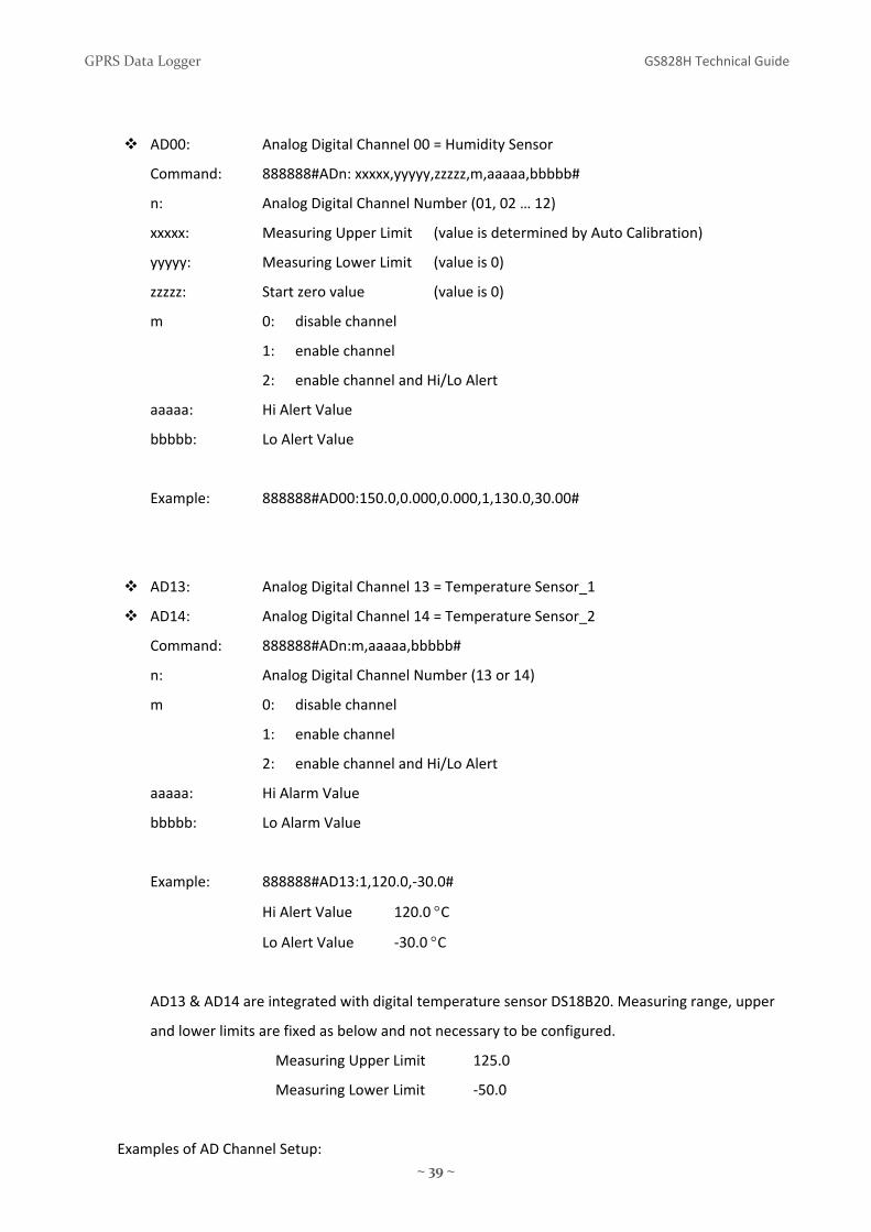
AD00: Analog Digital Channel 00 = Humidity Sensor
Command: 888888#ADn: xxxxx,yyyyy,zzzzz,m,aaaaa,bbbbb#
n: Analog Digital Channel Number (01, 02 … 12)
xxxxx: Measuring Upper Limit (value is determined by Auto Calibration)
yyyyy: Measuring Lower Limit (value is 0)
zzzzz: Start zero value (value is 0)
m 0: disable channel
1: enable channel
2: enable channel and Hi/Lo Alert
aaaaa: Hi Alert Value
bbbbb: Lo Alert Value
Example: 888888#AD00:150.0,0.000,0.000,1,130.0,30.00#
AD13: Analog Digital Channel 13 = Temperature Sensor_1
AD14: Analog Digital Channel 14 = Temperature Sensor_2
Command: 888888#ADn:m,aaaaa,bbbbb#
n: Analog Digital Channel Number (13 or 14)
m 0: disable channel
1: enable channel
2: enable channel and Hi/Lo Alert
aaaaa: Hi Alarm Value
bbbbb: Lo Alarm Value
Example: 888888#AD13:1,120.0,‐30.0#
Hi Alert Value 120.0 °C
Lo Alert Value ‐30.0 °C
AD13 & AD14 are integrated with digital temperature sensor DS18B20. Measuring range, upper
and lower limits are fixed as below and not necessary to be configured.
Measuring Upper Limit 125.0
Measuring Lower Limit ‐50.0
Examples of AD Channel Setup:
GPRS Data Logger GS828H Technical Guide
~ 40 ~
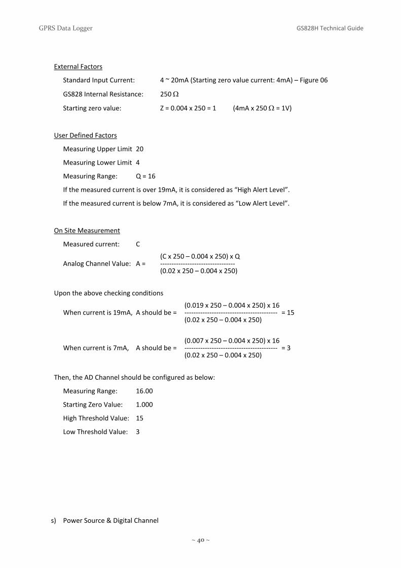
External Factors
Standard Input Current: 4 ~ 20mA (Starting zero value current: 4mA) – Figure 06
GS828 Internal Resistance: 250 Ω
Starting zero value: Z = 0.004 x 250 = 1 (4mA x 250 Ω = 1V)
User Defined Factors
Measuring Upper Limit 20
Measuring Lower Limit 4
Measuring Range: Q = 16
If the measured current is over 19mA, it is considered as “High Alert Level”.
If the measured current is below 7mA, it is considered as “Low Alert Level”.
On Site Measurement
Measured current: C
(C x 250 – 0.004 x 250) x Q Analog Channel Value: A = ‐‐‐‐‐‐‐‐‐‐‐‐‐‐‐‐‐‐‐‐‐‐‐‐‐‐‐‐‐‐‐‐‐ (0.02 x 250 – 0.004 x 250)
Upon the above checking conditions
(0.019 x 250 – 0.004 x 250) x 16 When current is 19mA, A should be = ‐‐‐‐‐‐‐‐‐‐‐‐‐‐‐‐‐‐‐‐‐‐‐‐‐‐‐‐‐‐‐‐‐‐‐‐‐‐‐‐‐ = 15 (0.02 x 250 – 0.004 x 250)
(0.007 x 250 – 0.004 x 250) x 16 When current is 7mA, A should be = ‐‐‐‐‐‐‐‐‐‐‐‐‐‐‐‐‐‐‐‐‐‐‐‐‐‐‐‐‐‐‐‐‐‐‐‐‐‐‐‐‐ = 3 (0.02 x 250 – 0.004 x 250)
Then, the AD Channel should be configured as below:
Measuring Range: 16.00
Starting Zero Value: 1.000
High Threshold Value: 15
Low Threshold Value: 3
s) Power Source & Digital Channel

GPRS Data Logger GS828H Technical Guide
~ 41 ~
Mode: GPRS DATA, GSM SMS, RS232 Port
Command: 888888#PA:xyyyyyymmmm
PA: xyyyyyymmmm
1st digit x: Setting of Power Source Alert
0 = No Alarm
1 = AC Power Resume Alarm
2 = AC Power Loss Alarm
3 = AC Power Resume/Loss Alarm
2nd~7th digit yyyyyy Setting of Channel IN01 ~ IN06
0 = Channel Disable
1 = Pulse Channel Enable
2 = NO ‐ Close Triggered Alarm
3 = NC ‐ Open Triggered Alarm
4 = Change State Triggered Alarm
8th~11 digit mmmm Setting of Channel IN07~ IN10
0 = Channel Disable
2 = NO‐ Close Triggered Alarm
3 = NC ‐ Open Triggered Alarm
4 = Change State Triggered Alarm
IN11 ~ IN16 On/Off Channel
No alarm function
t) Pulse Channel Start Zero Value
Mode: GPRS DATA, GSM SMS, RS232 Port
Command: 888888#LPx:aaaaaaaa#
x: Channel Number (1 ~ 6)
aaaaaaaa: Set the start zero value
Zero adjustment on matching with other measuring device on local site
Example: 888888#LP1:00123456#

GPRS Data Logger GS828H Technical Guide
~ 42 ~
u) Control Digital Output
Mode: GPRS DATA, GSM SMS, RS232 Port
Command: 888888#Oa:b#
a: Digital Output Channel 1 ~ 4
b: 1 – Output Close
0 – Output Open
Example: @888888888#O2:1# will turn on the relay 2
v) Alarm Triggered Digital Output Time Lapse
Mode: GPRS DATA, GSM SMS, RS232 Port
Command: 888888#OTa:xxxx#
a: Digital Output Channel 1 ~ 4
xxxx: period of relay turned ON (in seconds)
0000 means relay will be kept ON once alarm is triggered
Example: @888888888#OT2:0010#
Relay 2 will be turn on for 10 seconds when alarm is triggered
w) Digital Output Associated Alarms
Mode: GPRS DATA, GSM SMS, RS232 Port
Command: 888888#OCa:xyyyyyyyyyyyyzzpnnnnnnnnnn#
a: Digital Output Channel 1 ~ 4
Position of digits
1st digit x AD00 Humidity
2nd ~ 13th digits yyyyyyyyyyyy AD01 ~ 12
14th ~ 15th digits zz AD13 ~ 14 Temperature 1 & 2
16th digit p Power Source
17th ~ 26th digits nnnnnnnnnn IN01 ~ 10
When value = 1, this channel alarm will trigger the relay output ON.
When value = 0, this channel alarm will not trigger relay output.
• AD channel will be measured and checked for alarm level every 2 seconds

GPRS Data Logger GS828H Technical Guide
~ 43 ~
x) Local Data Transmission via RS232 port
Mode: GPRS DATA, GSM SMS, RS232 Port
Command: 888888#SE:y#
y: 1 enable data upload via RS232 port
upload interval is the same to the GPRS data upload interval
0 disable data upload via RS232 port
This feature is useful for bench testing before site installation.
Besides, it can be used for local data logging with “GS828_COM” software. Please contact your agent or 3gtrack for software copy and license.

GPRS Data Logger GS828H Technical Guide
~ 44 ~
23. How GS828H response on alarm?
Alarm is triggered when Digital Input state is changed or AD Input reading is higher or lower than user
preset values. User can be alerted via SMS or GPRS when alarm is triggered.
1) Configure the Alarm Test:
Command: 888888#SMSSETYY:X,ZZ, #
YY: Channel
00 Humidity Channel
01 ~ 12 AD01 ~ 12
13 TEMP 1
14 TEMP 2
15 Power Source Alert
16 ~ 25 IN01 ~ IN10
X: 0: Live Data will be uploaded [By Default]
1: Alarm Text preset by user will be uploaded
ZZ: Max. Length of Alarm Text
: Alarm Text e.g. Temperature_High [No space is allowed]
When Temperature 1 is over alert high value “85.00”, message “TEMP_HIGH” is sent to user.
888888#SMSSET13:1,10,TEMP_HIGH#
Alarm Phone receives message: STA:000000:TM:2009/12/08/16:10;A13:85.00,TEMP_HIGH
A) When X: 0 and alarm is triggered:
• Live Data will be uploaded to Server via GPRS
• Live Data will be sent to Control Centre via SMS
• Live Data will be sent to Alarm Phone via SMS
B) When X: 1 and alarm is triggered:
• Live Data will be uploaded to Server via GPRS
• Live Data will be sent to Control Centre via SMS
• Alarm Text will be sent to Alarm Phone via SMS
2) Read the Alarm Text from GS828H
Command: 888888#SMS:YY#
This is to retrieve the alarm text configured by above command for verification only.

GPRS Data Logger GS828H Technical Guide
~ 45 ~
24. Capturing, Logging & Upload
The section is to explain in detail the relationship among intervals of data capturing, logging and upload.
1. Data Capturing
• GS828H captures data from sensors every 2 seconds.
2. Data Logging
• GS828H logs the captured data into its internal memory in interval of 5/15/30/60 minutes options.
• Logging interval is user programmable.
• Every logging interval, one record of data will be stored in internal memory for upload.
3. Data Upload
• GS828H uploads the logged data records in interval from 5 second upto once a day.
• Upload interval is user programmable.
• When upload interval is larger than logging interval, there will be more than one record. Data will
be uploaded in packet containing more than one data record.
For example:
Logging Interval = 5 minutes Upload Interval = 15 minutes
At 8:00 am, GS828H will upload three data records logged at 7:50, 7:55, and 8:00 am in one packet.
At 8:15 am, GS828H will upload three data records logged at 8:05, 8:10, and 8:15 am in one packet.
• When upload interval is smaller than logging interval, real time data record will be uploaded.
For example:
Logging Interval = 5 minutes Upload Interval = 2 minutes
At 8:00 am, GS828H will upload one data record captured at 8:00 am.
At 8:02 am, GS828H will upload one data record captured at 8:02 am.
• However, data record at 8:02 am will not be logged (saved) in internal memory. But only data
captured at 8:00 and 8:15 am will be logged (saved) in internal memory.
4. Real Time Data Upload
• When GS828H receives 999999#STATUS# command, it will capture the instant data and upload it.
That means it will upload the real time data upon this command.
• However, this data record will not be logged (saved) in internal memory.

GPRS Data Logger GS828H Technical Guide
~ 46 ~
25. RS485 Port
• This port is ready for connecting to meters, transducers or other
measuring devices via RS485 port.
• Operation will not be available in Sleep Mode for GS828L.
ModBus Protocol
00 – 03 AD00 Analog Channel Value (IEE754 format)
04 – 07 AD01 Analog Channel Value (IEE754 format)
08 – 11 AD02 Analog Channel Value (IEE754 format)
12 – 15 AD03 Analog Channel Value (IEE754 format)
16 – 19 AD04 Analog Channel Value (IEE754 format)
20 – 23 AD05 Analog Channel Value (IEE754 format)
24 – 27 AD06 Analog Channel Value (IEE754 format)
28 – 31 AD07 Analog Channel Value (IEE754 format)
32 – 35 AD08 Analog Channel Value (IEE754 format)
36 – 39 AD09 Analog Channel Value (IEE754 format)
40 – 43 AD10 Analog Channel Value (IEE754 format)
44 – 47 AD11 Analog Channel Value (IEE754 format)
48 – 51 AD12 Analog Channel Value (IEE754 format)
52 – 55 AD13 Analog Channel Value (IEE754 format)
56 – 59 AD14 Analog Channel Value (IEE754 format)
60 – 63 P01 Pulse Channel Accumulated Value (hex format)
64 – 67 P02 Pulse Channel Accumulated Value (hex format)
68 – 71 P03 Pulse Channel Accumulated Value (hex format)
72 – 75 P04 Pulse Channel Accumulated Value (hex format)
76 – 79 P05 Pulse Channel Accumulated Value (hex format)
80 – 83 P06 Pulse Channel Accumulated Value (hex format)
84 Power AC Loss (AC: OXFF, Loss: OX00)

GPRS Data Logger GS828H Technical Guide
~ 47 ~
85 Digital Input Channel 1 Setup (OXAA: Pulse, OXFF: Close Alarm, OXOO: Open Alarm)
86 Digital Input Channel 2 Setup (OXAA: Pulse, OXFF: Close Alarm, OXOO: Open Alarm)
87 Digital Input Channel 3 Setup (OXAA: Pulse, OXFF: Close Alarm, OXOO: Open Alarm)
88 Digital Input Channel 4 Setup (OXAA: Pulse, OXFF: Close Alarm, OXOO: Open Alarm)
89 Digital Input Channel 5 Setup (OXAA: Pulse, OXFF: Close Alarm, OXOO: Open Alarm)
90 Digital Input Channel 6 Setup (OXAA: Pulse, OXFF: Close Alarm, OXOO: Open Alarm)
91 Digital Input Channel 7 Setup (OXFF: Close Alarm, OXOO: Open Alarm)
92 Digital Input Channel 8 Setup (OXFF: Close Alarm, OXOO: Open Alarm)
93 Digital Input Channel 9 Setup (OXFF: Close Alarm, OXOO: Open Alarm)
94 Digital Input Channel 10 Setup (OXFF: Close Alarm, OXOO: Open Alarm)
95 Digital Input Channel 11 Setup (OXFF: Close Alarm, OXOO: Open Alarm)
96 Digital Input Channel 12 Setup (OXFF: Close Alarm, OXOO: Open Alarm)
97 Digital Input Channel 13 Setup (OXFF: Close Alarm, OXOO: Open Alarm)
98 Digital Input Channel 14 Setup (OXFF: Close Alarm, OXOO: Open Alarm)
99 Digital Input Channel 15 Setup (OXFF: Close Alarm, OXOO: Open Alarm)
100 Digital Input Channel 16 Setup (OXFF: Close Alarm, OXOO: Open Alarm)
101 Relay Output 1
102 Relay Output 2
103 Relay Output 3
104 Relay Output 4

GPRS Data Logger GS828H Technical Guide
~ 48 ~
Examples:
Read AD1 Channel
Command: 01 03 00 00 00 04 00 00
01 Local PC ModBus Address
03 ModBus Command
00 00 AD1 Start Address (AD2 Start Address: 00 04)
00 04 Data Length in Byte
00 00 ModBus CRC Check (00 00 : No CRC is implemented)
Reply: 01 03 04 3F 17 7D A2 E6 CA
AD Value: 3F 17 7D A2 (IEE754) i.e. 0.59176
Read P01 Channel
Command: 01 03 00 10 00 04 00
Reply: 01 03 04 00 0D 6C 14 46 FF
Pulse Value: 00 0D 6C 14 (hex format) i.e. 879636
Relay Output 1 On
Command: 01 05 00 27 00 FF 00 00
Relay Output 1 Off
Command: 01 05 00 27 00 00 00 00
Relay Output 2 On
Command: 01 05 00 28 00 FF 00 00
Relay Output 2 Off
Command: 01 05 00 28 00 00 00 00
Set ModBus Protocol Local PC Address
Command: 00 07 07 01
Read Digital Input Output Status (Starting from address 0)
Command: 01 03 00 00 00 29 00 00

GPRS Data Logger GS828H Technical Guide
~ 49 ~
26. UPD Testing Software
Free bundled testing software “UDP Tool” is used to test the GPRS connection and device.
Schematics
Check the IP address of the PC and Router
Configure the Data Logger [Server IP] parameter as Router WAN IP
Configure the same port in UDP Tool and Data Logger
Router Setup
When router is installed between the PC and Internet, please open the ports for UDP and TCP.
Firewall Setup
On exceptions tab of Windows Firewall, click “UPD” program as exception or disable the firewall.
Open the ports defined by UDP Tool in the firewall setting.
Software Setup

GPRS Data Logger GS828H Technical Guide
~ 50 ~
Live Data Upload
Click [Create Socket] to start receiving data from Data Logger
Make sure that the acknowledge message “@888” must be added as auto reply in UDP protocol
Data will be uploaded from Data Logger to the Server in logging interval
Historical Data Upload
Enter the command “@888999999#REDEEM080910120003#” in auto reply

GPRS Data Logger GS828H Technical Guide
~ 51 ~
Historical Data is in packet format:
#STB:0001;TM:0705241115;V:8.65; T:04;C:01;A01:0.001|0.001|0.001|0.002;
A02:0.001|0.001|0.001|0.002;A03:0.001|0.001|0.001|0.002;A04:0.001|0.001|0.001|0.002|;
P01:00000000|00000000|00000000|00000000;P02:00000000|00000000|00000000|00000000;
P03:00000000|00000000|00000000|00000000;P04:00000000|00000000|00000000|00000000;
K:3333001|3333001|3333001|3333001;#
Resume Live Data Upload
Remember enter “@888” in auto reply
It will stop the historical data upload, and resume live data upload

GPRS Data Logger GS828H Technical Guide
~ 52 ~
27. TCP and UDP Operation
27.1 Data Format: TCP
This is a type of handshake data transmission with auto data recovery to ensure accuracy.
When the network signal coverage is weak, data transmission bandwidth will be huge.
27.2 Data Format: UDP
This is a type of data upload without checking the data accuracy. Data transmission bandwidth
can be expected or preset in advance.
In UPD format, packet data is considered as a secure way of data transmission to ensure the
receipt of data in control centre.
GS828 sends out the data packet to control centre (CTR IP). CTR IP replies with “@888”
message once it receives the data. GS828 will try to resend the data packet if reply message
“@888” is not received.
27.3 Packet Data
Control Centre sends data to GS828
This is the communication protocol maintaining the connection between Control Centre and
GS828. During the GPRS Internet connection, GS828 will automatically be assigned a Port
Number and IP address by the ISP provider. When the Internet connection is idle for a certain
period, the port number and IP address will be released. If CTR IP tries to send data to GS828 at
that moment, GS828 will not be able to receive the data because the last port number and IP
address cannot be located.
27.4 Secure Data Send/Receive (GS828H only)
When GS828 sends data to Control Centre, CTR IP will reply the confirmation message “@888”
once the data is received by CTR IP. Otherwise, GS828 will try to resend the data packet or
proceed the appropriate procedure.
27.5 Control Centre Check (GS828H only)
This can be used to check whether the software of Control Centre is running, or the CTR IP is
on line.

GPRS Data Logger GS828H Technical Guide
~ 53 ~
27.6 Secure Command Send/Receive (GS828H only)
When CTR IP receives the data from GS828, it will be acknowledged with the GS828 current
port number and IP address. A confirmation message “@888” will be replied to GS828. If any
control is necessary, CTR IP can send the command as “@888xxxxxxx” (e.g.
@888888888#SDx:y#) to GS828 at the same time. Usually, this method of sending command is
secure because the port number and IP address of GS828 will remain unchanged within 70
seconds after GS828 sends out data. It is normal that the port number and IP address of GS828
will only be released when GPRS Internet connection is idle after 70 seconds.
27.7 Ack. Interval (Heart Beat) (GS828H only)
Heart Beat is used to ensure the integrity of data transmission in UPD protocol. Each time
when GS828 sends out the live data or packet data, the Control Centre will reply with message
“@888”. If GS828 does not receive this reply message within the “Heart Beat Interval”, it will
send out “@888” message for three times every “Heart Beat Interval” until the reply message
“@888” is received from Control Centre.
After failed in three times of heart beat check, GS828 will proceed to “Redial” stage.
By default, heart beat interval is set to 128 seconds but user configurable. Once the reply
message is received from Control Centre, the “Heart Beat” counter will reset to zero and
restarts again. Logically, “Heart Beat Interval” should be larger than “Upload Interval” in order
to avoid repeated heart beat check and waste the GPRS air time.
27.8 Redial Interval (GS828H only)
When heart beat check fails three times continuously, GS828H will try to reconnect to the Internet, register a new port number & IP address, and send data after redial interval.
Usually, “Redial Interval” should be twice larger than “Upload Interval”.

GPRS Data
28. Safety a
All applicabelectromag
European U
Statement
We, 3gtrackconformity the Europe
The producstates of th
This produc
Customer S
View or dow
http://www
or email co
Logger
and Regulat
ble regulatorygnetic compa
Union Declar
k.com declarwith all appan Council D
ct is properlye EU with no
ct follows the
Support Link
wnload prod
w.3gtrack.co
ntact at:
ory Notice
y complianceatibility (EMC
ration of Con
re under ourlicable essenDirectives 200
y CE marked o restrictions
e provisions
ks
duct support
m
support@3
e statementsC) standards
nformity
r sole responntial requirem04/108/EC (E
demonstratis.
of the Europ
information
3gtrack.com
~ 54 ~
s, product ceand regulati
nsibility that tments necesEMC Directiv
ing this confo
pean Directiv
n from 3gtrac
ertification mions the Data
the product ssary for CE mve) and 2006
ormity and is
ves 2004/108
ck website:
markings, anda Logger is co
GS828 GPRSmarking, follo6/95/EC (Low
s for distribu
8/EC and 200
GS828H Te
d safety and ompliant wit
S Data Loggeowing the prw Voltage Dir
ution within a
06/95/EC.
echnical Guide
th.
r is in rovisions of rective).
all member
e

GPRS Data Logger GS828H Technical Guide
~ 55 ~
29. Manufacturer’s Disclaimer Statement
The information in this document is subject to change without notice and does not represent a
commitment on the part of the vendor. No warranty or representation, either expressed or implied, is
made with respect to the quality, accuracy or fitness for any particular purpose of this document. The
manufacturer reserves the right to make changes to the content of this document and/or the products
associated with it any time without obligation to notify any person or organization of such changes. In no
event will the manufacturer be liable for direct, indirect, special, incidental or consequential damages
arising out of the use or inability to use this product or documentation, even if advised of the possibility of
such damages. This document contains materials protected by copyright. All rights are reserved. No part of
this manual may be reproduced or transmitted in any form, by any means or for any purpose without
expressed written consent of its authors. Product names appearing in this document are mentioned of
identification purposes only. All trademarks, product names or brand names preparing in this document
are registered property of their respective owners.
Trademarks
3GTrack and GS828 are the registered trademarks of 3gtrack.com