gps autopilot automated steering system · trimble, the globe & triangle logo, aggps, ez-guide,...
TRANSCRIPT

Version 4.00Revision CJuly 2010Part Number 56694-00-E04
*56694-00-E04* F
INSTALLATION INSTRUCTIONS
AgGPS® Autopilot™
Automated Steering System
Case IH AccuGuide Ready
AFX 7010 / 8010
Axial-Flow 5080 / 6088 / 7010 / 7088 / 7120 / 8010 / 8120 / 9120
FLX 3020 Titan / 3520 / 4020 / 4520
MX Magnum 180 / 190 / 210 / 215 / 230 / 245 / 255 / 275 / 285 / 305 / 335
SPX 3320 Patriot / 3330 / 4420
STX 275 Steiger / 280 / 325 / 330 / 335 / 375 / 380 / 385 / 425 / 430 / 435 / 450 / 480 / 485 / 500 / 530 / 535
New Holland IntelliSteer Ready
CR 940 / 960 / 970 / 9040 / 9060 / 9070 / 9080
CX 8030 / 8040 / 8050 / 8060 / 8070 / 8080 / 8090
T 7030 / 7040 / 7050 / 7060
T 7510 / 7520 / 7530 / 7540 / 7550
T 8010 / 8020 / 8030 / 8040 / 8050
T 9020 / 9030 / 9040 / 9050 / 9060
TG 210 / 215 / 230 / 245 / 255 / 275 / 285 / 305
TJ 275 / 285 / 325 / 330 / 375 / 380 / 425 / 430 / 450 / 480 / 500 / 530

Agriculture Business AreaTrimble Agriculture Division10355 Westmoor DriveSuite #100Westminster, CO 80021USA(877) 447-7785 (US toll free)+1-408-856-6491 (International)[email protected]
Legal NoticesCopyright and Trademarks© 1999–2010, Trimble Navigation Limited. All rights reserved. Trimble, the Globe & Triangle logo, AgGPS, EZ-Guide, and FmX are trademarks of Trimble Navigation Limited, registered in the United States and in other countries. Autopilot, AutoSense, and FieldManager are trademarks of Trimble Navigation Limited.
All other trademarks are the property of their respective owners.
Release NoticeThis is the July 2010 release (Revision C) of the AgGPS Autopilot Automated Steering System Installation Instructions, part number 56694-00-E04. It applies to version 4.00 of the AgGPS Autopilot automated steering system.
The following limited warranties give you specific legal rights. You may have others, which vary from state/jurisdiction to state/jurisdiction.
Product Limited WarrantyTrimble warrants that this Trimble product and its internal components (the “Product”) shall be free from defects in materials and workmanship and will substantially conform to Trimble’s applicable published specifications for the Product for a period of one (1) year, starting from the earlier of (i) the date of installation, or (ii) six (6) months from the date of product shipment from Trimble. This warranty applies only to the Product if installed by Trimble or a distributor authorized by Trimble to perform Product installation services.
Software Components and Enhancements All Product software components (sometimes hereinafter also referred to as “Software”) are licensed and not sold. Any Software accompanied by a separate End User License Agreement (“EULA”) shall be governed by the terms, conditions, restrictions and limited warranty terms of such EULA notwithstanding the preceding paragraph. During the limited warranty period you will be entitled to receive, at no additional charge, such Fix Updates and Minor Updates to the Product software as Trimble may develop for general release, subject to the procedures for delivery to purchasers of Trimble products generally. If you have purchased the Product from an authorized Trimble distributor rather than from Trimble directly, Trimble may, at its option, forward the software Fix Update or Minor Update to the Trimble distributor for final distribution to you. Major Upgrades, new products, or substantially new software releases, as identified by Trimble are expressly excused from this enhancement process and limited warranty. Receipt of software updates shall not serve to extend the limited warranty period.
For purposes of this warranty the following definitions shall apply: (1) “Fix Update” means an error correction or other update created to fix a previous software version that does not substantially conform to its published specifications; (2) “Minor Update” occurs when enhancements are made to current features in a software program; and (3) “Major Upgrade” occurs when significant new features are added to software, or when a new product containing new features replaces the further development of a current product line. Trimble reserves the right to determine, in its sole discretion, what constitutes a significant new feature and Major Upgrade.
Warranty RemediesTrimble’s sole liability and your exclusive remedy under the warranties set forth above shall be, at Trimble’s option, to repair or replace any Product that fails to conform to such warranty (“Nonconforming Product”), and/or issue a cash refund up to the purchase price paid by you for any such Nonconforming Product, excluding costs of installation, upon your return of the Nonconforming Product to Trimble in accordance with Trimble’s standard return material authorization process. Such remedy may include reimbursement of the cost of repairs for damage to third-party equipment onto which the Product is installed, if such damage is found to be directly caused by the Product as reasonably determined by Trimble following a root cause analysis.
Warranty Exclusions and DisclaimerThese warranties shall be applied only in the event and to the extent that (i) the Products and Software are properly and correctly installed, configured, interfaced, maintained, stored, and operated in accordance with Trimble's relevant operator's manual and specifications, and; (ii) the Products and Software are not modified or misused. The preceding warranties shall not apply to, and Trimble shall not be responsible for defects or performance problems resulting from (i) the combination or utilization of the Product or Software with hardware or software
products, information, data, systems, interfaces or devices not made, supplied or specified by Trimble; (ii) the operation of the Product or Software under any specification other than, or in addition to, Trimble's standard specifications for its products; (iii) the unauthorized, installation, modification, or use of the Product or Software; (iv) damage caused by accident, lightning or other electrical discharge, fresh or salt water immersion or spray; or (v) normal wear and tear on consumable parts (e.g., batteries). Trimble does not warrant or guarantee the results obtained through the use of the Product.
THE WARRANTIES ABOVE STATE TRIMBLE'S ENTIRE LIABILITY, AND YOUR EXCLUSIVE REMEDIES, RELATING TO PERFORMANCE OF THE PRODUCTS AND SOFTWARE. EXCEPT AS OTHERWISE EXPRESSLY PROVIDED HEREIN, THE PRODUCTS, SOFTWARE, AND ACCOMPANYING DOCUMENTATION AND MATERIALS ARE PROVIDED “AS-IS” AND WITHOUT EXPRESS OR IMPLIED WARRANTY OF ANY KIND BY EITHER TRIMBLE NAVIGATION LIMITED OR ANYONE WHO HAS BEEN INVOLVED IN ITS CREATION, PRODUCTION, INSTALLATION, OR DISTRIBUTION INCLUDING, BUT NOT LIMITED TO, THE IMPLIED WARRANTIES OF MERCHANTABILITY AND FITNESS FOR A PARTICULAR PURPOSE, TITLE, AND NONINFRINGEMENT. THE STATED EXPRESS WARRANTIES ARE IN LIEU OF ALL OBLIGATIONS OR LIABILITIES ON THE PART OF TRIMBLE ARISING OUT OF, OR IN CONNECTION WITH, ANY PRODUCTS OR SOFTWARE. SOME STATES AND JURISDICTIONS DO NOT ALLOW LIMITATIONS ON DURATION OR THE EXCLUSION OF AN IMPLIED WARRANTY, SO THE ABOVE LIMITATION MAY NOT APPLY TO YOU.TRIMBLE NAVIGATION LIMITED IS NOT RESPONSIBLE FOR THE OPERATION OR FAILURE OF OPERATION OF GPS SATELLITES OR THE AVAILABILITY OF GPS SATELLITE SIGNALS.
Limitation of LiabilityTRIMBLE’S ENTIRE LIABILITY UNDER ANY PROVISION HEREIN SHALL BE LIMITED TO THE AMOUNT PAID BY YOU FOR THE PRODUCT OR SOFTWARE LICENSE. TO THE MAXIMUM EXTENT PERMITTED BY APPLICABLE LAW, IN NO EVENT SHALL TRIMBLE OR ITS SUPPLIERS BE LIABLE FOR ANY INDIRECT, SPECIAL, INCIDENTAL OR CONSEQUENTIAL DAMAGES WHATSOEVER UNDER ANY CIRCUMSTANCE OR LEGAL THEORY RELATING IN ANY WAY TO THE PRODUCTS, SOFTWARE AND ACCOMPANYING DOCUMENTATION AND MATERIALS, (INCLUDING, WITHOUT LIMITATION, DAMAGES FOR LOSS OF BUSINESS PROFITS, BUSINESS INTERRUPTION, LOSS OF BUSINESS INFORMATION, OR ANY OTHER PECUNIARY LOSS), REGARDLESS WHETHER TRIMBLE HAS BEEN ADVISED OF THE POSSIBILITY OF ANY SUCH LOSS AND REGARDLESS OF THE COURSE OF DEALING WHICH DEVELOPS OR HAS DEVELOPED BETWEEN YOU AND TRIMBLE. BECAUSE SOME STATES AND JURISDICTIONS DO NOT ALLOW THE EXCLUSION OR LIMITATION OF LIABILITY FOR CONSEQUENTIAL OR INCIDENTAL DAMAGES, THE ABOVE LIMITATION MAY NOT APPLY TO YOU.NOTE: THE ABOVE LIMITED WARRANTY PROVISIONS MAY NOT APPLY TO PRODUCTS OR SOFTWARE PURCHASED IN THE EUROPEAN UNION. PLEASE CONTACT YOUR TRIMBLE DEALER FOR APPLICABLE WARRANTY INFORMATION.
NoticesClass B Statement – Notice to Users. This equipment has been tested and found to comply with the limits for a Class B digital device, pursuant to Part 15 of the FCC rules. These limits are designed to provide reasonable protection against harmful interference in a residential installation. This equipment generates, uses, and can radiate radio frequency energy and, if not installed and used in accordance with the instructions, may cause harmful interference to radio communication. However, there is no guarantee that interference will not occur in a particular installation. If this equipment does cause harmful interference to radio or television reception, which can be determined by turning the equipment off and on, the user is encouraged to try to correct the interference by one or more of the following measures:
– Reorient or relocate the receiving antenna.– Increase the separation between the equipment and the receiver.– Connect the equipment into an outlet on a circuit different from that
to which the receiver is connected.– Consult the dealer or an experienced radio/TV technician for help.
Changes and modifications not expressly approved by the manufacturer or registrant of this equipment can void your authority to operate this equipment under Federal Communications Commission rules.
Notice to Our European Union CustomersFor product recycling instructions and more information, please go to: www.trimble.com/ev.shtml
Recycling in Europe: To recycle Trimble WEEE, Call
+31 497 53 2430, and ask for the "WEEE Associate"
Or
Mail a request for recycling instructions to:
Trimble Europe BV c/o Menlo Worldwide Logistics
Meerheide 455521 DZ Eersel, NL

Safety InformationAlways follow the instructions that accompany a Warning or Caution. The information they provide is intended to minimize the risk of personal injury and/or damage to property. In particular, observe safety instructions that are presented in the following format:
C WARNING – This alert warns of a potential hazard, which, if not avoided, can cause severe injury.
C CAUTION – This alert warns of a hazard or unsafe practice which, if not avoided, can cause injury or damage.
Note – An absence of specific alerts does not mean that there are no safety risks involved.
Warnings
C WARNING – When you are working on the vehicle’s hydraulic systems, vehicle attachments that are suspended can drop. If you are working around the vehicle, you could suffer serious injury if an attachment dropped on you. To avoid this risk, lower all vehicle attachments to the ground before you begin work.
C WARNING – If someone else attempts to drive the vehicle while you are working on or under it, you can suffer serious or fatal injuries. To avoid this possibility, install a lockout box on the battery terminal to prevent the battery from being reconnected, remove the key from the vehicle’s ignition switch, and attach a “Do not operate” tag in the cab.
C WARNING – Agricultural chemicals can pose serious health risks. If the vehicle has been used to apply agricultural chemicals, steam clean the vehicle to remove any chemical residue from the areas of the vehicle where you will be working.
C WARNING – Vehicle cabs can be quite high in the air. To avoid potentially serious injury through falling from this height, always use the steps and handrails, and face the vehicle, when you enter or exit it.
Cautions
C CAUTION – When the vehicle has been running, parts of the vehicle, including the engine and exhaust, can become extremely hot and can cause serious burns. To avoid burns, allow hot machine parts to cool before you begin working on them.
AgGPS Autopilot Automated Steering System Installation Instructions 3

Safety Information
C CAUTION – The system installation may bring you into contact with chemical substances, such as oil, which can cause poisoning. Wash your hands thoroughly after you finish working on the system.
C CAUTION – Battery posts, terminals, and related accessories contain lead and lead compounds, which can cause serious illness. To avoid ingesting lead, wash your hands thoroughly after touching the battery.
C CAUTION – Always wear protective equipment appropriate to the job conditions and the nature of the vehicle. This includes wearing protective glasses when you use pressurized air or water, and correct protective welder’s clothing when welding. Avoid wearing loose clothing or jewelry that can catch on machine parts or tools.
C CAUTION – Parts of the vehicle may be under pressure. To avoid injury from pressurized parts, relieve all pressure in oil, air, and water systems before you disconnect any lines, fittings, or related items. To avoid being sprayed by pressurized liquids, hold a rag over fill caps, breathers, or hose connections when you remove them. Do not use your bare hands to check for hydraulic leaks. Use a board or cardboard instead.
C CAUTION – Do not direct pressurized water at: - electronic or electrical components or connectors - bearings - hydraulic seals - fuel injection pumps - any other sensitive parts or components Set the hose pressure as low as practicable, and spray at a 45° to 90° angle. Keep the nozzle of the power washer away from the machine at the distance recommended by the manufacturer.
4 AgGPS Autopilot Automated Steering System Installation Instructions

ContentsSafety Information . . . . . . . . . . . . . . . . . . . . . . . . . . . . . . . . 3Warnings . . . . . . . . . . . . . . . . . . . . . . . . . . . . . . . . . . . . . . . . . . . . . . . . . . . . . . . 3
Cautions. . . . . . . . . . . . . . . . . . . . . . . . . . . . . . . . . . . . . . . . . . . . . . . . . . . . . . . . 3
1 Introduction . . . . . . . . . . . . . . . . . . . . . . . . . . . . . . . . . . . . 7Technical assistance . . . . . . . . . . . . . . . . . . . . . . . . . . . . . . . . . . . . . . . . . . . . . . . . 8
Your comments . . . . . . . . . . . . . . . . . . . . . . . . . . . . . . . . . . . . . . . . . . . . . . . . . . . 8
Manual system upgrade to Autopilot. . . . . . . . . . . . . . . . . . . . . . . . . . . . . . . . . . . . . . 9
EZ-Guide 500 manual guidance upgrade . . . . . . . . . . . . . . . . . . . . . . . . . . . . . . . 9
FmX integrated display . . . . . . . . . . . . . . . . . . . . . . . . . . . . . . . . . . . . . . . . . . 9
Required components . . . . . . . . . . . . . . . . . . . . . . . . . . . . . . . . . . . . . . . . . . . . . . . 9
Accessory kits . . . . . . . . . . . . . . . . . . . . . . . . . . . . . . . . . . . . . . . . . . . . . . . . 9
Preparing the vehicle for installation . . . . . . . . . . . . . . . . . . . . . . . . . . . . . . . . . . . . . 10
2 Display Installation . . . . . . . . . . . . . . . . . . . . . . . . . . . . . . . 11FmX integrated display components . . . . . . . . . . . . . . . . . . . . . . . . . . . . . . . . . . . . . 12
EZ-Guide 500 lightbar components . . . . . . . . . . . . . . . . . . . . . . . . . . . . . . . . . . . . . 13
With SNB900 radio for 900 MHz RTK corrections (if equipped) . . . . . . . . . . . . . . . 13
Preparing the FmX integrated display . . . . . . . . . . . . . . . . . . . . . . . . . . . . . . . . . . . . 15
Installing the FmX integrated display . . . . . . . . . . . . . . . . . . . . . . . . . . . . . . . . . . . . 16
FmX integrated display: Connecting accessory options . . . . . . . . . . . . . . . . . . . . . . . . . 16
AgCam . . . . . . . . . . . . . . . . . . . . . . . . . . . . . . . . . . . . . . . . . . . . . . . . . . . 16
Speaker . . . . . . . . . . . . . . . . . . . . . . . . . . . . . . . . . . . . . . . . . . . . . . . . . . . 17
Preparing the EZ-Guide 500 lightbar . . . . . . . . . . . . . . . . . . . . . . . . . . . . . . . . . . . . . 18
Connecting the EZ-Guide 500 lightbar cables . . . . . . . . . . . . . . . . . . . . . . . . . . . . . . . 19
Installing the EZ-Guide 500 lightbar . . . . . . . . . . . . . . . . . . . . . . . . . . . . . . . . . . . . . 22
EZ-Guide 500 lightbar and FmX integrated display: Installing the GPS antenna and plate . . . 24
FmX integrated display: Installing the RTK radio antenna . . . . . . . . . . . . . . . . . . . . . . . 26
3 Receiver Installation. . . . . . . . . . . . . . . . . . . . . . . . . . . . . . . 27Antenna and receiver installation options . . . . . . . . . . . . . . . . . . . . . . . . . . . . . . . . . 28
Possible mounting methods . . . . . . . . . . . . . . . . . . . . . . . . . . . . . . . . . . . . . . 28
AgGPS 252/262 GPS receiver . . . . . . . . . . . . . . . . . . . . . . . . . . . . . . . . . . . . . . . . . . 28
With AgGPS 900 radio module (if equipped) components . . . . . . . . . . . . . . . . . . . 28
Installing the AgGPS 252/262 GPS receiver . . . . . . . . . . . . . . . . . . . . . . . . . . . . . . . . . 29
With an AgGPS 450/900 radio module (if equipped) . . . . . . . . . . . . . . . . . . . . . . . 29
FmX / Autopilot / Factory-ready CNH vehicle / external receiver. . . . . . . . . . . . . . . . . . . 31
Installing the display jumper . . . . . . . . . . . . . . . . . . . . . . . . . . . . . . . . . . . . . . . . . . 32
Installing the display jumper for all vehicles, except combines . . . . . . . . . . . . . . . . . . . . 32
MX, TG, T8000 and SPX 3320 / 3330 only . . . . . . . . . . . . . . . . . . . . . . . . . . . . . . 32
FLX, SPX4420, TJ, T9000 and STX only . . . . . . . . . . . . . . . . . . . . . . . . . . . . . . . 33
All controllers . . . . . . . . . . . . . . . . . . . . . . . . . . . . . . . . . . . . . . . . . . . . . . . 34
AgGPS Autopilot Automated Steering System Installation Instructions 5

Contents
Installing the display jumper for combines . . . . . . . . . . . . . . . . . . . . . . . . . . . . . . . . . 36
4 Controller Installation . . . . . . . . . . . . . . . . . . . . . . . . . . . . . . 41FmX / Factory ready CNH vehicle. . . . . . . . . . . . . . . . . . . . . . . . . . . . . . . . . . . . . . . 42
EZ-Guide 500 system / Autopilot / SNB900 RTK radio. . . . . . . . . . . . . . . . . . . . . . . . . . 43
EZ-Guide 500 system / Autopilot / SNB900 Rover RTK radio . . . . . . . . . . . . . . . . . . . . . 44
EZ-Guide 500 system / Autopilot / Ag 3000 modem . . . . . . . . . . . . . . . . . . . . . . . . . . . 45
Cable overview. . . . . . . . . . . . . . . . . . . . . . . . . . . . . . . . . . . . . . . . . . . . . . . . . . . 46
Installing the controller for vehicles other than combines . . . . . . . . . . . . . . . . . . . . . . . 47
MX, TG, T8000 and SPX 3320 / 3330 only . . . . . . . . . . . . . . . . . . . . . . . . . . . . . . 47
FLX, SPX4420, TJ, T9000 and STX only . . . . . . . . . . . . . . . . . . . . . . . . . . . . . . . 48
All controllers . . . . . . . . . . . . . . . . . . . . . . . . . . . . . . . . . . . . . . . . . . . . . . . 49
Installing the controller for combines . . . . . . . . . . . . . . . . . . . . . . . . . . . . . . . . . . . . 51
Configuring CAN jumper for an STX/TJ 2006 model . . . . . . . . . . . . . . . . . . . . . . . . . . . 57
Configuring CAN jumper for an STX/TJ 2007 model . . . . . . . . . . . . . . . . . . . . . . . . . . . 58
5 NavController II and the Combine Display Configuration. . . . . . . . . . 59Configuring the NavController II . . . . . . . . . . . . . . . . . . . . . . . . . . . . . . . . . . . . . . . 60
Configuring the combine display . . . . . . . . . . . . . . . . . . . . . . . . . . . . . . . . . . . . . . . 61
Enabling the guidance for combines . . . . . . . . . . . . . . . . . . . . . . . . . . . . . . . . . . . . . 63
6 Final Machine Check . . . . . . . . . . . . . . . . . . . . . . . . . . . . . . . 65Performing the final machine check . . . . . . . . . . . . . . . . . . . . . . . . . . . . . . . . . . . . . 66
6 AgGPS Autopilot Automated Steering System Installation Instructions
C H A P T E R
1
Introduction 1Technical assistance
Your comments
Manual system upgrade to Autopilot
Required components
Preparing the vehicle for installation
This manual describes how to install the Trimble® AgGPS® Autopilot™ automated steering system.
Even if you have used other Global Positioning System (GPS) products before, Trimble recommends that you spend some time reading this manual to learn about the special features of this product. If you are not familiar with GPS, visit the Trimble website (www.trimble.com) for an interactive look at Trimble and GPS.
AgGPS Autopilot Automated Steering System Installation Instructions 7

1 Introduction
Technical assistanceIf you have a problem and cannot find the information you need in the product documentation, contact Trimble technical support:
1. Go to the Trimble website (www.trimble.com).
2. Click the Support & Training link at the top of the screen, select Support and then select Support A–Z list of products.
3. Scroll to the bottom of the list.
4. Click the submit an inquiry link. A form appears.
5. Complete the form and then click Send.
Your commentsYour feedback about the supporting documentation helps us to improve it with each revision. Email your comments to [email protected].
8 AgGPS Autopilot Automated Steering System Installation Instructions

Introduction 1
Manual system upgrade to Autopilot
EZ-Guide 500 manual guidance upgrade
FmX integrated display
Required components
Accessory kits
Retain Remove
EZ-Guide® 500 lightbarAntenna for EZ-Guide 500 lightbar
Antenna to receiver cable(Optional) Remote keypad
Power connection cable (for modification)
Retain Remove
Trimble FmX™ integrated display: P/N 93100-xxAntenna for FmX integrated display: P/N 68040-00SAntenna to receiver cable: P/N 50449
Power cable: P/N 67258 & 66694
Kits required Special tools
Platform kit: P/N 56694-00 (included with controller) Deutsch DT pins and crimp toolsDeutsch DTM pins, sockets, and crimp tools
Accessory options
Remote engage switch assembly – standard Euro: P/N 57227-10
Remote engage switch assembly – full Euro: P/N 57227-20Remote engage foot pedal: P/N 57259
AgGPS Autopilot Automated Steering System Installation Instructions 9

1 Introduction
Preparing the vehicle for installation
Step 1
Park the vehicle on a hard, level surface. Block the front and rear wheels.
Step 2
Align the steering straight ahead. On an articulated vehicle, install the articulation locks.
Step 3
Remove all dirt and debris from the areas of the vehicle where the AgGPS Autopilot™ system will be installed.
Step 4
Open all kit boxes and check the contents of the box against the packing list/s. Lay all of the parts out on a clean workbench.
Note – The left and right sides of the vehicle are referenced while standing behind the unit, facing the normal direction of travel.
10 AgGPS Autopilot Automated Steering System Installation Instructions

C H A P T E R
2
Display Installation 2In this chapter:
FmX integrated display components
EZ-Guide 500 lightbar components
Preparing the FmX integrated display
Installing the FmX integrated display
FmX integrated display: Connecting accessory options
Preparing the EZ-Guide 500 lightbar
Connecting the EZ-Guide 500 lightbar cables
Installing the EZ-Guide 500 lightbar
EZ-Guide 500 lightbar and FmX integrated display: Installing the GPS antenna and plate
FmX integrated display: Installing the RTK radio antenna
This chapter describes and how to install and connect the FmX® integrated display, or the EZ-Guide 500 lightbar in the vehicle.
AgGPS Autopilot Automated Steering System Installation Instructions 11
2 Display Installation
FmX integrated display components
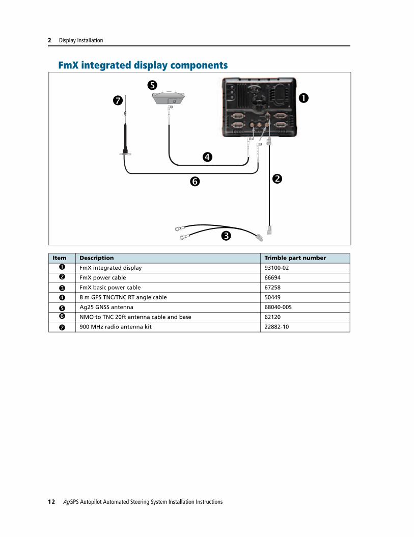
Item Description Trimble part number
c FmX integrated display 93100-02
d FmX power cable 66694
e FmX basic power cable 67258
f 8 m GPS TNC/TNC RT angle cable 50449
g Ag25 GNSS antenna 68040-00S
h NMO to TNC 20ft antenna cable and base 62120
i 900 MHz radio antenna kit 22882-10
c
d
e
f
g
h
i
12 AgGPS Autopilot Automated Steering System Installation Instructions

Display Installation 2
EZ-Guide 500 lightbar components
With SNB900 radio for 900 MHz RTK corrections (if equipped)
Item Description Part number
c EZ-Guide 500 lightbar 66100-xx
d GPS antenna 77038-00
e SBN900 radio antenna 22882-00
f SBN900 radio antenna magnetic mount 62109
g GPS antenna cable 50449
h N Female to REV. POL TNC Male 62114
i SNB900 radio 68480-X0
j Remote keypad (optional) 66030-00
k CNH Hybrid to GPS cable 67120
l NAVController II 55563-00
m Factory-installed harness -
n EZ-Guide 500-to-Autopilot cable 62754
o Port expansion cable 62690
p Power tap to EZ-Guide 500 63185
LAB
EL
ETHERNET
REVERSEPOLARITY
AUDIO
VENT: DO NOT REMOVE
e
f
g
c
d
h
i
j
k
l
m
n
o
p
q
rs
AgGPS Autopilot Automated Steering System Installation Instructions 13

2 Display Installation
q External interface cable 62749
r EZ-Guide 500 power cable 62817
s Radio to EZ-Guide 500 61158
Item Description Part number
14 AgGPS Autopilot Automated Steering System Installation Instructions

Display Installation 2
Preparing the FmX integrated display
Step 1
Locate the FmX integrated display, the RAM mount, and the RAM mount clamp.
Step 2
Use the provided metric hardware to attach the RAM mount to the rear of the display.
Step 3
Attach the RAM mount to the rear of the display.
AgGPS Autopilot Automated Steering System Installation Instructions 15

2 Display Installation
Installing the FmX integrated display
C WARNING – To avoid potentially serious personal injury or illness, and to prevent damage to equipment, make sure that you read and understand the Safety Information chapter.
Step 1
Decide where you will mount the display in the vehicle cab. Use the provided bolts to attach the bar mount to the rail
Step 2
Attach the free end of the RAM mount to the bar mount. Tighten the clamp on the RAM mount so that the display is secure.
FmX integrated display: Connecting accessory options
AgCam
The AgCam and AgCam cable are accessory items that you can purchase separately from the FmX integrated display. The FmX integrated display will allow for up to four video inputs.
Step 1
Locate the AgCam and AgCam cable.
Step 2
Mount the AgCam in a secure location and then route the cable towards the FmX integrated display.
Step 3
Connect the AgCam cable to the FmX integrated display adaptor cable.
16 AgGPS Autopilot Automated Steering System Installation Instructions

Display Installation 2
Step 4
Connect the FmX integrated display to AgCam adaptor cable to one of the open 12 pin connectors on the back of the display.
Speaker
Step 1
Locate the speaker and cable assembly that connects to the FmX integrated display.
Step 2
Mount the speaker in the required location and then route the cable to the FmX integrated display.
Step 3
Connect the speaker cable to one of the open 12 pin connectors on the back of the display.
AgGPS Autopilot Automated Steering System Installation Instructions 17

2 Display Installation
Preparing the EZ-Guide 500 lightbarNote – Before you attach the lightbar to the RAM mount, connect the EZ-Guide 500 cables to the back of the lightbar.
Step 1
Locate the EZ-Guide 500 lightbar, the RAM mount and hardware, and the RAM mount clamp.
Step 2
Attach the RAM mount diamond base to the display using the hardware provided.
18 AgGPS Autopilot Automated Steering System Installation Instructions

Display Installation 2
Connecting the EZ-Guide 500 lightbar cablesNote – Before you attach the lightbar to the RAM mount, connect the EZ-Guide 500 cables to the back of the lightbar.
Step 1
Connect the port expansion cable (P/N 62609) to the AUX port on the back of the lightbar.
Step 2
Connect the EZ-Guide 500 power cable (P/N 62817) to the PWR port on the back of the lightbar.
Step 3
Connect the 2-pin connector on the port expansion cable and the 12-pin connector on the power cable to the matching connectors on the EZ-Guide 500-to-Autopilot cable (P/N 62754).
Step 4
Feed the GPS antenna cable into the cab and then connect it to the antenna port on the back of the lightbar.
AgGPS Autopilot Automated Steering System Installation Instructions 19

2 Display Installation
Step 5
With keypad
Connect the external interface cable (P/N 66030-00) to the serial port on the back of the lightbar.
Connect the remote keypad to the KPAD serial port on the external interface cable.
Connect the appropriate cable to the GPS serial port on the interface cable:
Radio type Cable to connect
SNB900 radio EZ-Guide 500-to-radio cable (P/N 61158)
PDL 450 radio PDL radio power/data cable (P/N 51861-00)
20 AgGPS Autopilot Automated Steering System Installation Instructions

Display Installation 2
Without keypad
Connect the appropriate cable to the serial port on the back of the lightbar:
Step 6
Connect the other end of the radio cable to the radio.
Step 7
Connect the remaining connector on the PDL radio power/data cable to the matching connector on the power tap cable (P/N 63185).
Connect the connector at the other end of the power tap cable to the EZ-Guide 500 power cable.
Radio type Cable to connect
SNB900 radio EZ-Guide 500-to-radio cable (P/N 61158)
PDL 450 radio PDL radio power/data cable (P/N 51861-00)
AgGPS Autopilot Automated Steering System Installation Instructions 21

2 Display Installation
Installing the EZ-Guide 500 lightbar
C WARNING – To avoid potentially serious personal injury or illness, and to prevent damage to equipment, make sure that you read and understand the Safety Information chapter.
Step 1
Select the location for the lightbar in the cab. The mounting location requires a bar that the RAM mount can be attached to.
Select a location in the cab that:
• allows a clear view of the display.
• does not obscure the tractor instruments.
Step 2
Use the provided hardware to mount the RAM mount bracket to the bar. Feed the EZ-Guide 500 antenna and the Autopilot system cables to the display location. If equipped, feed the radio cable to the same location.
Step 3
Attach the other end of the RAM mount to the bar mount. Attach the antenna and the Autopilot system cables to the lightbar.
Note – The following steps describe this process in greater detail.
22 AgGPS Autopilot Automated Steering System Installation Instructions

Display Installation 2
Step 4
Connect the two round connectors on the EZ-Guide 500-to-Autopilot cable to the power and extension ports on the back of the lightbar.
Step 5
Feed the GPS antenna cable into the cab and then connect it to the antenna port on the back of the lightbar.
Step 6
Adjust the position of the EZ-Guide 500 lightbar so you can comfortably access the display buttons and then tighten the clamp on the RAM mount so the display is held securely in place.
Ensure that the other end of the EZ-Guide 500 cable is connected to the connection labeled “GPS” on the controller wiring harness.
Port expansion cablePower connector
Antenna cable
AgGPS Autopilot Automated Steering System Installation Instructions 23

2 Display Installation
EZ-Guide 500 lightbar and FmX integrated display: Installing the GPS antenna and plate
C WARNING – To avoid potentially serious personal injury or illness, and to prevent damage to equipment, make sure that you read and understand the Safety Information chapter.
Step 1
If the antenna has magnets built in, omit this step.
Otherwise, attach the large magnet with a 5/8" stud to the GPS antenna.
24 AgGPS Autopilot Automated Steering System Installation Instructions

Display Installation 2
Step 2
L1/L2 dual band antenna (RTK, OmniSTAR, DGPS)
For repeatable positioning, place the antenna against the lip at the narrow end of the V plate.
L1 single band antenna (WAAS, EGNOS, VBS, Beacon)
Attach the antenna to the center of the 4" x 6" plate.
Step 3
Both models
Attach the antenna/receiver cable to the antenna and then route the cable into the cab through the rubber grommet at the base of the rear window. Secure the cable along the way.
AgGPS Autopilot Automated Steering System Installation Instructions 25

2 Display Installation
FmX integrated display: Installing the RTK radio antenna
C WARNING – To avoid potentially serious personal injury or illness, and to prevent damage to equipment, make sure that you read and understand the Safety Information chapter.
Step 1
Connect the radio antenna to the magnetic antenna base
Step 2
Attach the magnetic radio antenna base to the rear f the V plate on the roof. If the cable does not reach the V plate, use the 4" x 6" plate with the VHB provided to relocate the antenna.
Step 3
Route cable from the vehicle roof into the cab, and connect the radio cable to the FmX integrated display.
26 AgGPS Autopilot Automated Steering System Installation Instructions

C H A P T E R
3
Receiver Installation 3In this chapter:
Antenna and receiver installation options
AgGPS 252/262 GPS receiver
Installing the AgGPS 252/262 GPS receiver
FmX / Autopilot / Factory-ready CNH vehicle / external receiver
Installing the display jumper
Installing the display jumper for all vehicles, except combines
Installing the display jumper for combines
This chapter describes how to install an AgGPS 252/262 receiver and AgGPS radio module, an AgGPS 332 receiver and antenna, or an AgGPS 442 receiver and antenna.
Note – To install the antenna for an EZ-Guide 500 system, see Chapter 2, Display Installation.
AgGPS Autopilot Automated Steering System Installation Instructions 27

3 Receiver Installation
Antenna and receiver installation options
Possible mounting methods
AgGPS 252/262 GPS receiver
With AgGPS 900 radio module (if equipped) components
GPS receiver V plate on spar (removable)
VHB plate on roof (removable)
Standard AgGPS 252/262 plate bolted to spar (permanent)
AgGPS 252/262 receiver F x FAgGPS 432/442 receiver F x x
Item Description Trimble part number
c AgGPS 252/262 antenna/receiver
d AgGPS 900 radio module (if equipped)
cd
28 AgGPS Autopilot Automated Steering System Installation Instructions

Receiver Installation 3
Installing the AgGPS 252/262 GPS receiver
With an AgGPS 450/900 radio module (if equipped)
Step 1
GPS receiver only
Install the receiver onto the quick attach mounting plate with three bolts, washers, and lock nuts. Torque the nuts to 1.9 Nm (17 in-lbs).
Step 2
GPS receiver and radio
Place the GPS receiver on top of the AgGPS 900 radio and use the provided self-tapping screws to fasten the radio and receiver together.
Step 3
GPS receiver and radio
Plug the radio connector into Port B on the receiver.
Note – Skip this step for STX installations.
AgGPS Autopilot Automated Steering System Installation Instructions 29

3 Receiver Installation
Step 4
GPS receiver and radio
a. Install the receiver and radio assembly onto the quick attach mounting plate with three bolts, washers, and lock nuts. Torque the nuts to 1.9 Nm (17 in-lbs).
b. Attach the antenna to the quick attach plate and then screw antenna lead into the radio.
30 AgGPS Autopilot Automated Steering System Installation Instructions
Receiver Installation 3
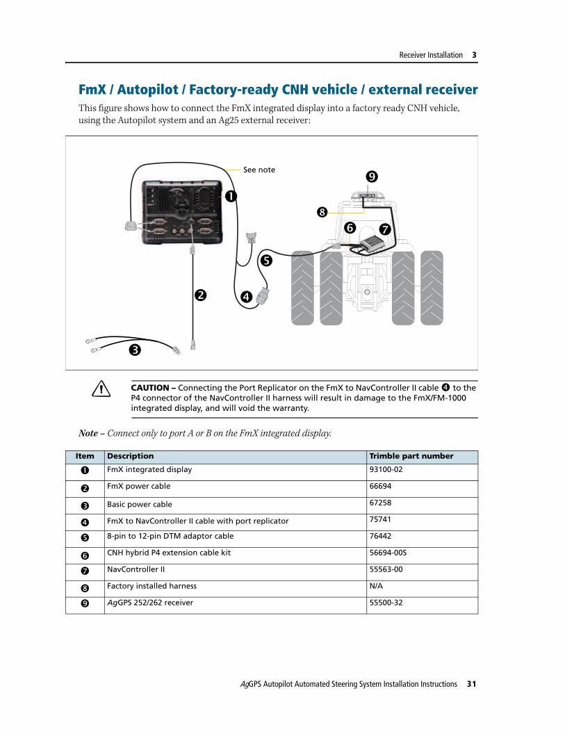
FmX / Autopilot / Factory-ready CNH vehicle / external receiverThis figure shows how to connect the FmX integrated display into a factory ready CNH vehicle, using the Autopilot system and an Ag25 external receiver:
C CAUTION – Connecting the Port Replicator on the FmX to NavController II cable f to the P4 connector of the NavController II harness will result in damage to the FmX/FM-1000 integrated display, and will void the warranty.
Note – Connect only to port A or B on the FmX integrated display.
Item Description Trimble part number
c FmX integrated display 93100-02
d FmX power cable 66694
e Basic power cable 67258
f FmX to NavController II cable with port replicator 75741
g 8-pin to 12-pin DTM adaptor cable 76442
h CNH hybrid P4 extension cable kit 56694-00S
i NavController II 55563-00
j Factory installed harness N/A
k AgGPS 252/262 receiver 55500-32
d
e
f
g
h i
j
kSee note
c
AgGPS Autopilot Automated Steering System Installation Instructions 31

3 Receiver Installation
Installing the display jumper
Locate the P-4 jumper from the cabling kit provided with the controller.
Installing the display jumper for all vehicles, except combines
MX, TG, T8000 and SPX 3320 / 3330 only
Step 1
Remove the net from the rear cab wall.
Item Description
c Display jumper
d Display connector
cd
32 AgGPS Autopilot Automated Steering System Installation Instructions

Receiver Installation 3
Step 2
Remove the four wing nuts from the rear controller cover and remove the cover.
Step 3
Remove the protective covers from the auto-guidance connectors.
Continue with All controllers, page 34.
FLX, SPX4420, TJ, T9000 and STX only
Step 1
Open the instructor seat and remove the tray. Unscrew the four hex spacers from the cab floor.
AgGPS Autopilot Automated Steering System Installation Instructions 33

3 Receiver Installation
Step 2
Locate the guidance harness under the instructor seat.
Continue with All controllers, below.
All controllers
Step 1
Locate the 40-pin Deutsch connector at the end of the guidance cable.
Wire ID# Conn term Conn term Description
Guidance Jumper
1 (red/white) P1-33 P4-2 Autopilot display port RS232 TX
2 (orange) P1-4 P4-3 Autopilot display port RS232 RX
3 (green) P1-14 P4-5 Autopilot display port RS232 GND
34 AgGPS Autopilot Automated Steering System Installation Instructions

Receiver Installation 3
Step 2
Remove the plastic seals in pins 33, 4, and 14.
Use the table above as a guide to insert the loose wires on the display jumper (P4).
Note – The cavity numbers are embossed on the connector and read left to right and top to bottom.
Note – Wire ends from the display jumper (P4) for power are not used.
4
14
33
AgGPS Autopilot Automated Steering System Installation Instructions 35

3 Receiver Installation
Installing the display jumper for combines
Step 1
Locate the NavController II wiring harness n. This is available from the CNH GPS Guidance Kit.
Step 2
Locate the 40-pin Deutsch connector (H) at the end of the guidance cable.
Step 3
Locate cavity 4 and 33 on the back of the connector.
Note – The connector is displayed without wires for clarity. The cavity numbers are embossed on the connector and read left to right and top to bottom. 33
4
36 AgGPS Autopilot Automated Steering System Installation Instructions

Receiver Installation 3
Step 4
Use the pin removal tools to extract the red and blue wires from cavities 4 and 33.
Step 5
Use a DTM06-12S connector (not provided) and remove the plastic seals from the pin 2 and 3 positions.
Step 6
Remove the wedge from the connector.
AgGPS Autopilot Automated Steering System Installation Instructions 37

3 Receiver Installation
Step 7
Insert the loose wires from the 40-pin connector into the DTM06-12S connector as shown in the table.
Pull back on the wires to seat them and then replace the wedge.
Step 8
Remove the plastic seal in pin 14.
Locate cavity 4 and 33.
Note – The connector is displayed without wires for clarity. The cavity numbers are embossed on the connector and read left to right and top to bottom.
Wire ID # Connector terminal DTM06-12S
Description
1212 (blue) DTM06-2 NMEA RS232 TX
1211 (red) DTM06-3 NMEA RS232 RX
4
33
14
38 AgGPS Autopilot Automated Steering System Installation Instructions

Receiver Installation 3
Step 9
Insert the loose wires on the Display jumper (P4) into the 40-pin connector as shown in the table.
Wire ID # Connection terminal Guidance
Connection terminal Jumper
Description
1 (red/white) P1-33 P4-2 Display RS232 TX
2 (orange) P1-4 P4-3 Display RS232 RX
3 (green) P1-14 P4-5 Display RS232 GND
AgGPS Autopilot Automated Steering System Installation Instructions 39

3 Receiver Installation
40 AgGPS Autopilot Automated Steering System Installation Instructions
C H A P T E R
4
Controller Installation 4In this chapter:
FmX / Factory ready CNH vehicle
EZ-Guide 500 system / Autopilot / SNB900 RTK radio
EZ-Guide 500 system / Autopilot / SNB900 Rover RTK radio
EZ-Guide 500 system / Autopilot / Ag 3000 modem
Cable overview
Installing the controller for vehicles other than combines
Installing the controller for combines
Configuring CAN jumper for an STX/TJ 2006 model
Configuring CAN jumper for an STX/TJ 2007 model
This chapter describes how to install the controller unit.
AgGPS Autopilot Automated Steering System Installation Instructions 41

4 Controller Installation
FmX / Factory ready CNH vehicleThis figure shows how to connect the FmX integrated display into a factory ready CNH vehicle, using RTK corrections:
C CAUTION – Connecting the Port Replicator on the FmX to NavController II cable j to the P4 connector of the NavController II harness will result in damage to the FmX/FM-1000 integrated display, and will void the warranty.
Item Description Trimble part number
c FmX integrated display 93100-02
d FmX power cable 66694
e Basic power cable 67258
f 8 m GPS TNC/TNC RT angle cable 50449
g Ag25 GNSS antenna 68040-00S
h NMO to TNC 20ft antenna cable and base 62120
i 900 MHz radio antenna kit 22882-10
j FmX to NavController II cable with port replicator 75741
k CNH hybrid to GPS cable 67120
l NavController II 55563-00
m Factory-installed harness N/A
c
d
e
f
g
h
i
j
k
l
m
42 AgGPS Autopilot Automated Steering System Installation Instructions

Controller Installation 4
EZ-Guide 500 system / Autopilot / SNB900 RTK radioThis figure shows how to connect an EZ-Guide 500 system to an Autopilot system using an SNB900 RTK radio:
Item Description Part number
c EZ-Guide 500 lightbar 66100-xx
d GPS antenna 77038-00
e SBN900 radio antenna 22882-00
f SBN900 radio antenna magnetic mount 62109
g GPS antenna cable 50449
h N Female to REV. POL TNC Male 62114
i SNB900 radio 68480-X0
j Remote keypad (optional) 66030-00
k CNH Hybrid to GPS cable 67120
l NAVController II 55563-00
m Factory-installed harness -
n EZ-Guide 500-to-Autopilot cable 62754
o Port expansion cable 62690
p Power tap to EZ-Guide 500 63185
LAB
EL
ETHERNET
REVERSEPOLARITY
AUDIO
VENT: DO NOT REMOVE
e
f
g
c
d
h
i
j
k
l
m
n
o
p
q
rs
AgGPS Autopilot Automated Steering System Installation Instructions 43

4 Controller Installation
EZ-Guide 500 system / Autopilot / SNB900 Rover RTK radioThis figure shows how to connect and EZ-Guide 500 system to an Autopilot system using an SNB900 rover RTK radio for corrections.
q External interface cable 62749
r EZ-Guide 500 power cable 62817
s Radio to EZ-Guide 500 61158
Item Description Part number
c EZ-Guide 500 lightbar 66100-xx
d GPS antenna 77038-00
e 900 MHz radio antenna kit 22882-10
f Antenna cable, magnetic base NMO-to-TNC 72122
g GPS antenna cable 50449
h N Female to REV. POL TNC Male 62114
i SNB900 radio 66768-00-XX
j Remote keypad: optional 66030-00
Item Description Part number
LAB
EL
cd
e
f
gh
k
j
i
n
m l
op
q
r
44 AgGPS Autopilot Automated Steering System Installation Instructions

Controller Installation 4
EZ-Guide 500 system / Autopilot / Ag 3000 modemThis figure shows how to connect an EZ-Guide 500 system to an Autopilot system with an Ag3000 modem:
k CNH Hybrid to GPS cable 67120
l NAVController II 55563-00
m Factory-installed harness -
n EZ-Guide 500-to-Autopilot cable 62754
o Port expansion cable 62609
p External interface cable 62749
q EZ-Guide 500 power cable 62817
r EZ-Guide 500 to SNB900R 74798
Item Description Part number
c EZ-Guide 500 lightbar 66100-xx
d GPS antenna 77038-00
e Ag3000 breakout cable 70433
f Ag3000 interface cable 72639
g AG3000 Modem 68600-xx
Item Description Part number
LAB
EL
cd
e
f
k
lm
g
hi
j
n
op
AgGPS Autopilot Automated Steering System Installation Instructions 45

4 Controller Installation
Cable overview
Note – You may find it easier to establish the cable connections to the controller before you install the controller. Read through the sections in this chapter and then decide the order in which you wish to proceed. If you attach the cables first, ensure that you feed the cables through any necessary routes.
h Remote keypad: optional 66030-00
i EZ-Guide 500 power cable 62817
j Port expansion cable 62609
k CNH Hybrid to GPS cable 67120
l NAVController II 55563-00
m Factory-installed harness -
n EZ-Guide 500-to-Autopilot cable 62754
o GPS antenna cable 50449
p External interface cable 62749
Item Description
c Status LED
d Sonalert jumper
e Sonalert connector
Item Description Part number
c
d
e
46 AgGPS Autopilot Automated Steering System Installation Instructions

Controller Installation 4
Installing the controller for vehicles other than combines
MX, TG, T8000 and SPX 3320 / 3330 only
Step 1
Remove the net from the rear cab wall.
Step 2
Remove the four wing nuts from the rear controller cover and remove the cover.
Step 3
Remove the protective covers from the auto-guidance connectors.
Continue with All controllers, page 49
AgGPS Autopilot Automated Steering System Installation Instructions 47

4 Controller Installation
FLX, SPX4420, TJ, T9000 and STX only
Step 1
Open the instructor seat and remove the tray. Unscrew the four hex spacers from the cab floor.
Step 2
Locate the guidance harness under the instructor seat.
Continue with All controllers, below.
48 AgGPS Autopilot Automated Steering System Installation Instructions

Controller Installation 4
All controllers
Step 1
Locate the 24-pin Deutsch connector at the end of the guidance cable.
Step 2
Remove the plastic seals in pins 16 and 19
Note – The cavity numbers are embossed on the connector and read left to right and top to bottom.
Wire ID# Conn term Conn term Description
Guidance Jumper
1 (gray) P2-16 LED-A Sensor 12 V OUT
2 (brown) P2-19 LED-B Status LED
19 16
AgGPS Autopilot Automated Steering System Installation Instructions 49

4 Controller Installation
Step 3
Use the table above as a guide to insert the wire ends on the supplied status LED jumper.
Step 4
Locate the 40-pin Deutsch connector at the end of the guidance cable.
Step 5
Remove the plastic seals in pins 5 and 15.
Use the table below as a guide to insert the loose wires on the Sonalert jumper (P9) into the 40-pin connector.
Wire ID# Conn term Conn term Description
Guidance Jumper
4 (white) P1-5 P9-A Sonalert V+
5 (gray) P1-15 P9-B Sonalert GND
50 AgGPS Autopilot Automated Steering System Installation Instructions

Controller Installation 4
Installing the controller for combines
Step 1
Locate the NavController II wiring harness n. This is available from the CNH GPS Guidance Kit.
Step 2
Locate the 40-pin Deutsch connector (H) at the end of the guidance cable.
Step 3
Locate cavity 4 and 33 on the back of the connector.
Note – The connector is displayed without wires for clarity. The cavity numbers are embossed on the connector and read left to right and top to bottom.
4
33
AgGPS Autopilot Automated Steering System Installation Instructions 51

4 Controller Installation
Step 4
Use the pin removal tools to extract the red and blue wires from cavities 4 and 33.
Step 5
Use a DTM06-12S connector (not provided) and remove the plastic seals from the pin 2 and 3 positions.
Step 6
Remove the wedge from the connector.
Step 7
Insert the loose wires from the 40-pin connector into the DTM06-12S connector as shown in the table.
52 AgGPS Autopilot Automated Steering System Installation Instructions

Controller Installation 4
Pull back on the wires to seat them and then replace the wedge.
Step 8
Remove the plastic seals in pin 5 and 15.
Note – The connector is displayed without wires for clarity. The cavity numbers are embossed on the connector and read left to right and top to bottom.
Step 9
Insert the loose wires on the Sonalert jumper (P9) into the 40-pin connector as shown in the table.
Wire ID # Connector terminal DTM06-12S
Description
1212 (blue) DTM06-2 NMEA RS232 TX
1211 (red) DTM06-3 NMEA RS232 RX
1514
33
4 5
AgGPS Autopilot Automated Steering System Installation Instructions 53

4 Controller Installation
Step 10
Locate the 24-pin Deutsch connector (G) at the end of the NavController II harness.
Use the table below as a guide to insert the wire ends on the supplied status LED jumper
Step 11
After the calibration is done, plug the DTM06-12S connector into connector (F) of the NavController II wiring harness n shown in Step 1.
Wire ID # Connection terminal Guidance
Connection terminal Jumper
Description
4 (white) P1-5 P9-A Sonalert V+
5 (gray) P1-15 P9-B Sonalert GND
Wire ID# Conn term Conn term Description
Guidance Jumper
1 (gray) P2-16 LED-A Sensor 12 V OUT
2 (brown) P2-19 LED-B Status LED
54 AgGPS Autopilot Automated Steering System Installation Instructions

Controller Installation 4
Note – The same connector (F) will also be used to configure the NavController II with cable P/N 50166. See Chapter 5, NavController II and the Combine Display Configuration for more information.
Step 12
Locate the four standoffs that are mounted onto the cab floor at the right side of the seat.
Locate the AgGPS 252/262 cable o that comes from the cab roof.
Step 13
Connect the connector (D) of the NavController II harness n to the existing connector under the right module.
Step 14
AgGPS 252/262 receiver only
Connect the connector (E) of the NavController II harness n to the connector (R) of the receiver cable o.
The receiver cable must be connected to Port A on the AgGPS 252/262 receiver.
AgGPS Autopilot Automated Steering System Installation Instructions 55

4 Controller Installation
Step 15
EZ-Guide 500 only
Connector (E) of the NavController II harness n remains unplugged.
Step 16
Install the controller upside down onto the standoffs and ensure that the connectors are facing the seat.
Mount the cover m over the controller and secure with the wing nuts .
56 AgGPS Autopilot Automated Steering System Installation Instructions

Controller Installation 4
Configuring CAN jumper for an STX/TJ 2006 modelNote – If the STX/TJ model has a VT harness installed, skip this section.
Step 1
If no VT harness is present, remove the jumper from connector 377F, located in the electrical bay to the right of the seat.
Step 2
Move the jumper to connector 214F, which is located under the liner and filter behind the cab seat.
Connect the two gray 12-pin DTM connectors in the fuse panel area together.
Step 3
Verify the two black 8-pin connectors in the fuse panel area are also connected together.
AgGPS Autopilot Automated Steering System Installation Instructions 57

4 Controller Installation
Configuring CAN jumper for an STX/TJ 2007 modelPerform these steps if the STX/TJ is a 2007 model with a serial number >= Z7F105338.
Note – If the STX/TJ model has an AFS Pro 600/IntelliView Plus II display harness installed, skip this section.
The #2 connector on the CNH inside auto-guidance cab harness may be difficult to find. It can be located in the right rear corner of the electrical bay to the right of the seat.
When the 4WD is provided as auto-guidance-ready, the inside auto-guidance harness connector is left unplugged.
The matching tractor harness connection has a CAN Bus jumper installed.
Step 1
Remove the jumper from the matching tractor harness connection and then place the jumper on the harness connector shown.
Step 2
Ensure that the connection shown is connected to the tractor harness. This establishes the power and ground circuit for the Autopilot NavController II controller and an AgGPS 252/262 GPS receiver.
c
d
e
58 AgGPS Autopilot Automated Steering System Installation Instructions

C H A P T E R
5
NavController II and the Combine Display Configuration 5In this chapter:
Configuring the NavController II
Configuring the combine display
Enabling the guidance for combines
This chapter describes how to configure the NavController II and the combine display.
AgGPS Autopilot Automated Steering System Installation Instructions 59
5 NavController II and the Combine Display Configuration
Configuring the NavController II
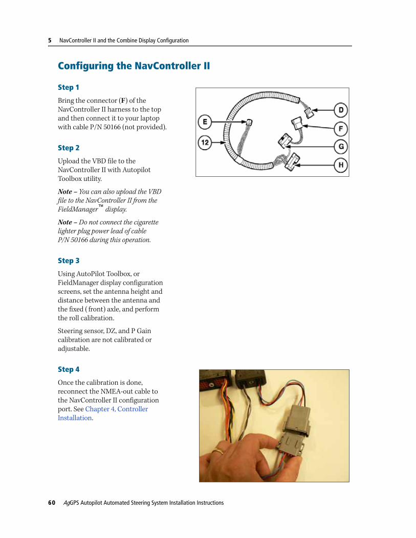
Step 1
Bring the connector (F) of the NavController II harness to the top and then connect it to your laptop with cable P/N 50166 (not provided).
Step 2
Upload the VBD file to the NavController II with Autopilot Toolbox utility.
Note – You can also upload the VBD file to the NavController II from the FieldManager™ display.
Note – Do not connect the cigarette lighter plug power lead of cable P/N 50166 during this operation.
Step 3
Using AutoPilot Toolbox, or FieldManager display configuration screens, set the antenna height and distance between the antenna and the fixed ( front) axle, and perform the roll calibration.
Steering sensor, DZ, and P Gain calibration are not calibrated or adjustable.
Step 4
Once the calibration is done, reconnect the NMEA-out cable to the NavController II configuration port. See Chapter 4, Controller Installation.
60 AgGPS Autopilot Automated Steering System Installation Instructions

NavController II and the Combine Display Configuration 5
Configuring the combine display
Step 1
Select the Toolbox icon to open the Configuration menu.
Step 2
Enable DGPS guidance: Select Drive / Autoguidance Type and then select DGPS.
Step 3
Disable the CNH NavController II: Select NAV / NAV II Installed and then select No.
Note – If the Guidance dll is not installed on the combine, the NAV tab will not be available.
AgGPS Autopilot Automated Steering System Installation Instructions 61
5 NavController II and the Combine Display Configuration
Step 4
GPS Receiver Configuration
The Yield Monitor does not use GPS positions
a. Un-install GPS.
b. From the Configuration menu, select GPS / GPS Location and then select Not Installed.
The Yield Monitor uses GPS positions
a. Install GPS.
b. From the Configuration menu, select GPS / GPS Location and then select the location where the antenna was installed.
Step 5
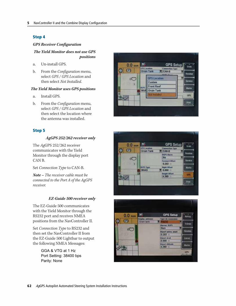
AgGPS 252/262 receiver only
The AgGPS 252/262 receiver communicates with the Yield Monitor through the display port CAN B.
Set Connection Type to CAN-B.
Note – The receiver cable must be connected to the Port A of the AgGPS receiver.
EZ-Guide 500 receiver only
The EZ-Guide 500 communicates with the Yield Monitor through the RS232 port and receives NMEA positions from the NavController II.
Set Connection Type to RS232 and then set the NavController II from the EZ-Guide 500 Lightbar to output the following NMEA Messages:
GGA & VTG at 1 Hz Port Setting: 38400 bps Parity: None
62 AgGPS Autopilot Automated Steering System Installation Instructions

NavController II and the Combine Display Configuration 5
Enabling the guidance for combinesAfter a power cycle, before you are allowed to engage in Automatic mode, you must enable guidance:
Step 1
Turn the steering wheel one complete revolution to the left and one complete revolution to the right so that the manual override sensor is detected.
AutoGuidance is now enabled and the Automatic mode can be engaged from the Trimble display or from the optional Remote Engage Foot Pedal.
Step 2
Press and hold the AutoGuidance switch for about 3 seconds. You will hear a tone confirming that the first condition is filled out.
The switch is available from the armrest.
Note – For Axial Flow series 5088/6088/7088 combines, first turn the separator on to complete these steps
View of the AFX AXIAL-FLOW right hand module
View of the CR CX right hand module
AgGPS Autopilot Automated Steering System Installation Instructions 63

5 NavController II and the Combine Display Configuration
64 AgGPS Autopilot Automated Steering System Installation Instructions

C H A P T E R
6
Final Machine Check 6In this chapter:
Performing the final machine check
This chapter describes how to perform a final check of the vehicle. When the check is done, the standard vehicle calibration should be performed.
AgGPS Autopilot Automated Steering System Installation Instructions 65

6 Final Machine Check
Performing the final machine check
C WARNING – To avoid potentially serious personal injury or illness, and to prevent damage to equipment, make sure that you read and understand the Safety Information chapter.
Step 1
Connect the battery.
Step 2
Connect and run the AgGPS Autopilot Toolbox II software for system setup and calibration. When you select the vehicle type, ensure that you select a vehicle that is marked with the “AG” or “IS” suffix. These vehicle profiles are for factory-ready systems and are different to a complete aftermarket installation. For more information, refer to the AgGPS Autopilot Toolbox II Software User Guide. After you have selected the correct vehicle type, check for any faults. Correct any faults before you continue.
Step 3
Open the Diagnostic page of the AgGPS Autopilot Toolbox II software and ensure that all signals from the hydraulics and sensors are active.
66 AgGPS Autopilot Automated Steering System Installation Instructions