graphic data manager, osg40 modbus-slave · operating instructions supplementary description...
TRANSCRIPT
Operating Instructions Supplementary Description
Graphic Data Manager, OSG40 Modbus-Slave
Connection to Modbus via Modbus Slave Plug-in Module
DE: Seite 2 EN: Page 26
BA260R/09/a2/07.08No. 71068853 Software GMU00xA, V1.10.xx
Graphic Data Manager / Modbus ______________________________________________________________________________________
2
Inhaltsverzeichnis: 1 Allgemeines .............................................................................................................................................. 3
1.1 Voraussetzungen.................................................................................................................................................3 1.2 Lieferumfang ......................................................................................................................................................3 1.3 Steckmodul Modbus RTU....................................................................................................................................4
1.3.1 Anschlüsse...................................................................................................................................................4 1.3.2 Kommunikations-LED ..................................................................................................................................4 1.3.3 Status-LED...................................................................................................................................................4 1.3.4 Modbus RTU Verbinder (DB9F) ....................................................................................................................4
1.4 Steckmodul Modbus TCP....................................................................................................................................5 1.4.1 Anschlüsse...................................................................................................................................................5 1.4.2 Netzwerk-Status-LED...................................................................................................................................5 1.4.3 Status-LED...................................................................................................................................................5 1.4.4 Link-LED.....................................................................................................................................................5
1.5 Funktionsbeschreibung........................................................................................................................................6 1.6 Kontrolle auf Vorhandensein des Modbus-Moduls ................................................................................................6
2 Einstellungen im Setup .............................................................................................................................. 7 2.1 Analogkanäle ......................................................................................................................................................9 2.2 Mathematikkanäle ..............................................................................................................................................9 2.3 Digitalkanäle.......................................................................................................................................................9
3 Datenübertragung.................................................................................................................................... 12 3.1 Allgemeines ......................................................................................................................................................12 3.2 Adressierung.....................................................................................................................................................13
3.2.1 Modbus-Master � Gerät: Analogkanäle Momentanwert .............................................................................13 3.2.2 Modbus-Master � Gerät: Digitaleingang Zustand .......................................................................................14 3.2.3 Gerät � Modbus-Master: Analogeingänge Momentanwert..........................................................................15 3.2.4 Gerät � Modbus-Master: Mathematikkanäle Resultat .................................................................................16 3.2.5 Gerät � Modbus-Master: Digitalkanäle (Zustand, Impulszähler) ..................................................................18 3.2.6 Gerät � Modbus-Master: Integrierte Analogkanäle (Gesamtzähler)..............................................................20 3.2.7 Gerät � Modbus-Master: Integrierte Mathematikkanäle (Gesamtzähler)......................................................21 3.2.8 Modbus-Master � Gerät: Texte übertragen ................................................................................................22 3.2.9 Aufbau der Prozesswerte ............................................................................................................................23
3.2.9.1 32-Bit Fließkommazahl (IEEE-754) ......................................................................................................23 3.2.9.2 Status der Fließkommazahl ..................................................................................................................23 3.2.9.3 Digitale Zustände.................................................................................................................................24
4 Abkürzungsverzeichnis/Begriffserklärungen............................................................................................ 25 5 Index ...................................................................................................................................................... 25
Graphic Data Manager / Modbus ______________________________________________________________________________________
3
1 Allgemeines Bitte beachten Sie folgende Zeichen:
Hinweis: Ratschläge zur sicheren Inbetriebnahme
Achtung: Nichtbeachtung kann zum Defekt des Gerätes oder Fehlfunktionen führen!
1.1 Voraussetzungen Das Modbus-Modul kann nur genutzt werden ab Firmware-Version V1.02.00 des Geräts in Verbindung mit der PC-Software ab Version 1.23.1.0. Die Mathematikkanäle 9 bis 12 werden nur ab Firmware Version V1.10.00 mit Applikationspaket „Energie“ unterstützt.
1.2 Lieferumfang Gerät mit eingebautem Modbus-Modul. Diese Bedienungsanleitung befindet sich auf der mitgelieferten Doku-CD.
Graphic Data Manager / Modbus ______________________________________________________________________________________
4
1.3 Steckmodul Modbus RTU
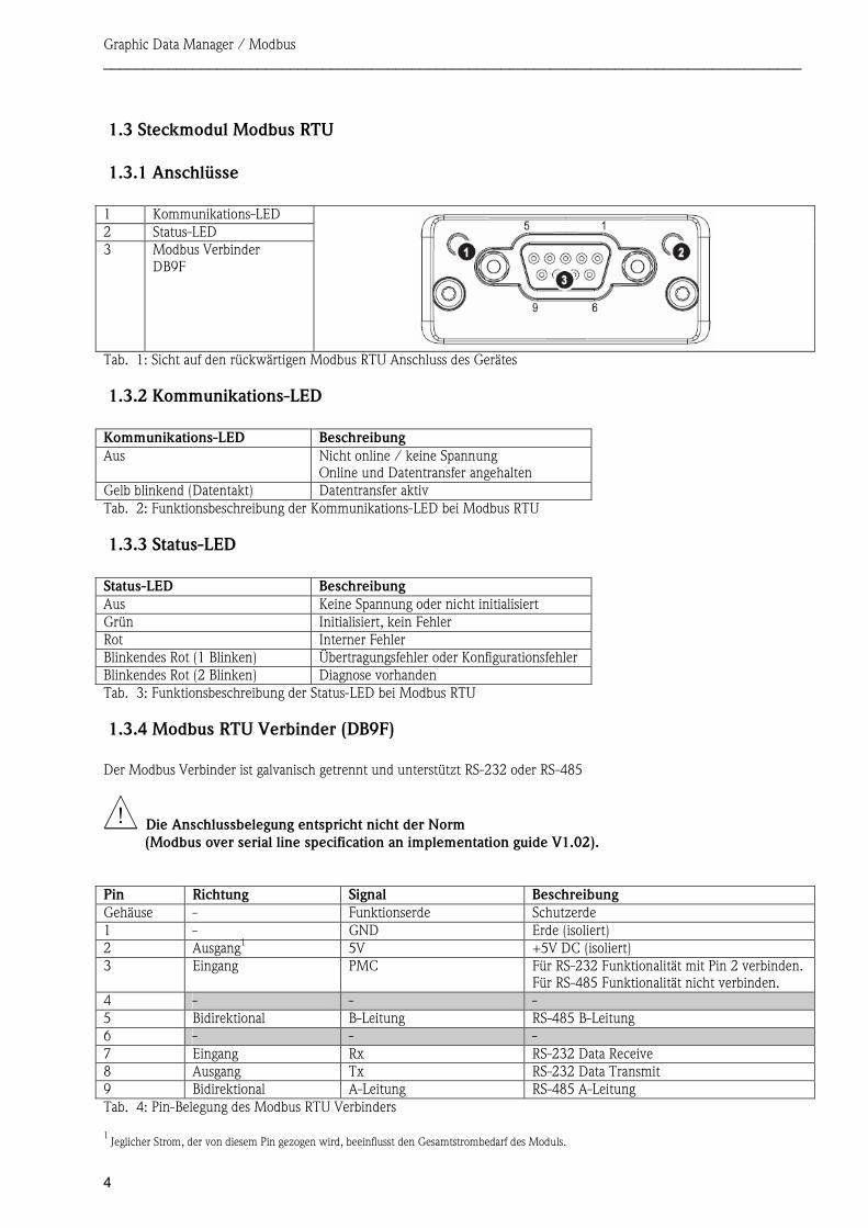
1.3.1 Anschlüsse 1 Kommunikations-LED 2 Status-LED 3 Modbus Verbinder
DB9F
1.3.2 Kommunikations-LED Kommunikations-LED Beschreibung Aus Nicht online / keine Spannung
Online und Datentransfer angehalten Gelb blinkend (Datentakt) Datentransfer aktiv
1.3.3 Status-LED Status-LED Beschreibung Aus Keine Spannung oder nicht initialisiert Grün Initialisiert, kein Fehler Rot Interner Fehler Blinkendes Rot (1 Blinken) Übertragungsfehler oder Konfigurationsfehler Blinkendes Rot (2 Blinken) Diagnose vorhanden
1.3.4 Modbus RTU Verbinder (DB9F) Der Modbus Verbinder ist galvanisch getrennt und unterstützt RS-232 oder RS-485
Die Anschlussbelegung entspricht nicht der Norm (Modbus over serial line specification an implementation guide V1.02).
Pin Richtung Signal Beschreibung Gehäuse - Funktionserde Schutzerde 1 - GND Erde (isoliert) 2 Ausgang1 5V +5V DC (isoliert) 3 Eingang PMC Für RS-232 Funktionalität mit Pin 2 verbinden.
Für RS-485 Funktionalität nicht verbinden. 4 - - -5 Bidirektional B-Leitung RS-485 B-Leitung 6 - - -7 Eingang Rx RS-232 Data Receive 8 Ausgang Tx RS-232 Data Transmit 9 Bidirektional A-Leitung RS-485 A-Leitung
1Jeglicher Strom, der von diesem Pin gezogen wird, beeinflusst den Gesamtstrombedarf des Moduls.
Tab. 1: Sicht auf den rückwärtigen Modbus RTU Anschluss des Gerätes
Tab. 2: Funktionsbeschreibung der Kommunikations-LED bei Modbus RTU
Tab. 3: Funktionsbeschreibung der Status-LED bei Modbus RTU
Tab. 4: Pin-Belegung des Modbus RTU Verbinders
Graphic Data Manager / Modbus ______________________________________________________________________________________
5
1.4 Steckmodul Modbus TCP
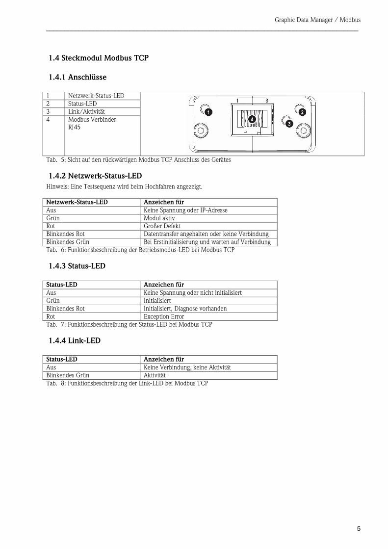
1.4.1 Anschlüsse 1 Netzwerk-Status-LED 2 Status-LED 3 Link/Aktivität 4 Modbus Verbinder
RJ45
1.4.2 Netzwerk-Status-LED Hinweis: Eine Testsequenz wird beim Hochfahren angezeigt. Netzwerk-Status-LED Anzeichen für Aus Keine Spannung oder IP-Adresse Grün Modul aktiv Rot Großer Defekt Blinkendes Rot Datentransfer angehalten oder keine Verbindung Blinkendes Grün Bei Erstinitialisierung und warten auf Verbindung
1.4.3 Status-LED Status-LED Anzeichen für Aus Keine Spannung oder nicht initialisiert Grün Initialisiert Blinkendes Rot Initialisiert, Diagnose vorhanden Rot Exception Error
1.4.4 Link-LED Status-LED Anzeichen für Aus Keine Verbindung, keine Aktivität Blinkendes Grün Aktivität
Tab. 5: Sicht auf den rückwärtigen Modbus TCP Anschluss des Gerätes
Tab. 6: Funktionsbeschreibung der Betriebsmodus-LED bei Modbus TCP
Tab. 7: Funktionsbeschreibung der Status-LED bei Modbus TCP
Tab. 8: Funktionsbeschreibung der Link-LED bei Modbus TCP
Graphic Data Manager / Modbus ______________________________________________________________________________________
6
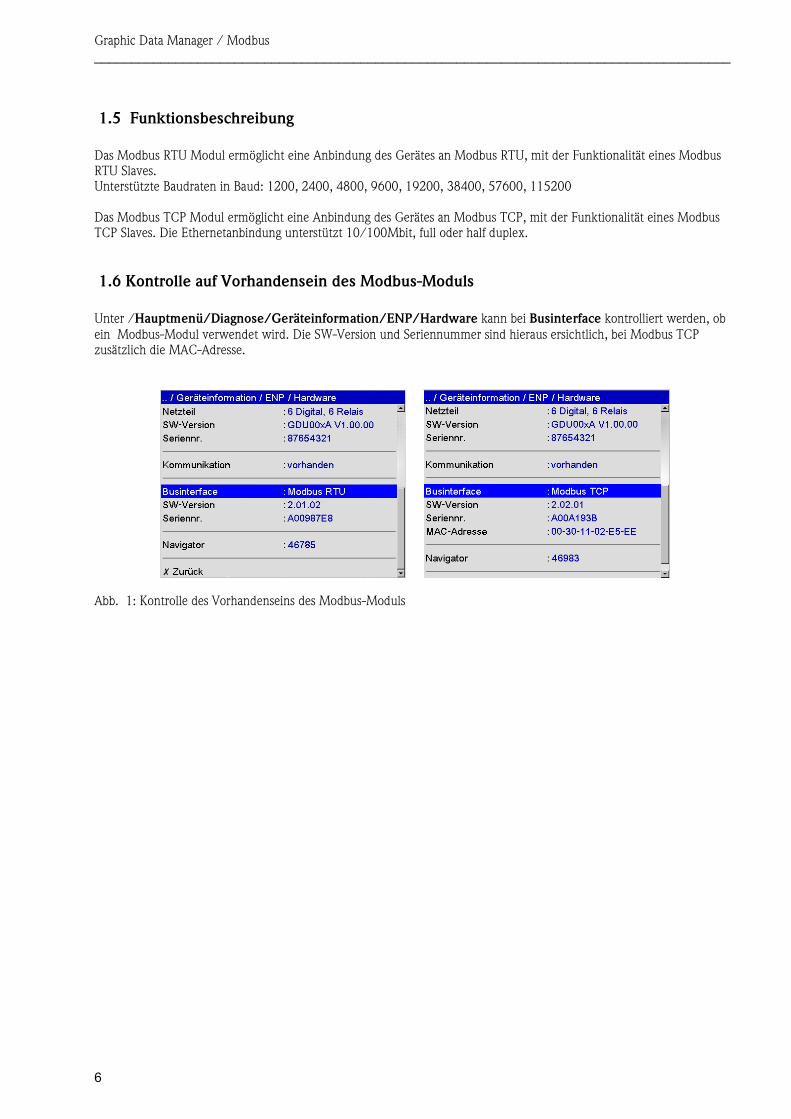
1.5 Funktionsbeschreibung Das Modbus RTU Modul ermöglicht eine Anbindung des Gerätes an Modbus RTU, mit der Funktionalität eines Modbus RTU Slaves. Unterstützte Baudraten in Baud: 1200, 2400, 4800, 9600, 19200, 38400, 57600, 115200 Das Modbus TCP Modul ermöglicht eine Anbindung des Gerätes an Modbus TCP, mit der Funktionalität eines Modbus TCP Slaves. Die Ethernetanbindung unterstützt 10/100Mbit, full oder half duplex.
1.6 Kontrolle auf Vorhandensein des Modbus-Moduls Unter /Hauptmenü/Diagnose/Geräteinformation/ENP/Hardware kann bei Businterface kontrolliert werden, ob ein Modbus-Modul verwendet wird. Die SW-Version und Seriennummer sind hieraus ersichtlich, bei Modbus TCP zusätzlich die MAC-Adresse.
Abb. 1: Kontrolle des Vorhandenseins des Modbus-Moduls
Graphic Data Manager / Modbus ______________________________________________________________________________________
7
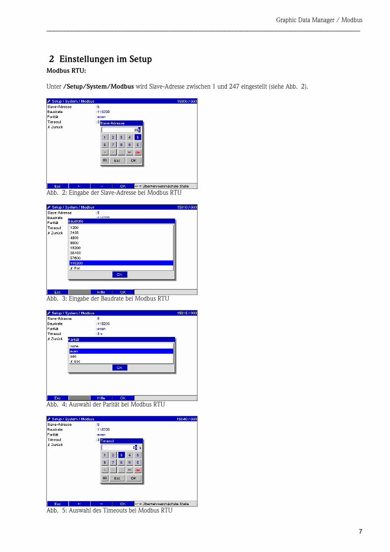
2 Einstellungen im Setup Modbus RTU: Unter /Setup/System/Modbus wird Slave-Adresse zwischen 1 und 247 eingestellt (siehe Abb. 2).
Abb. 3: Eingabe der Baudrate bei Modbus RTU
Abb. 4: Auswahl der Parität bei Modbus RTU
Abb. 5: Auswahl des Timeouts bei Modbus RTU
Abb. 2: Eingabe der Slave-Adresse bei Modbus RTU
Graphic Data Manager / Modbus ______________________________________________________________________________________
8
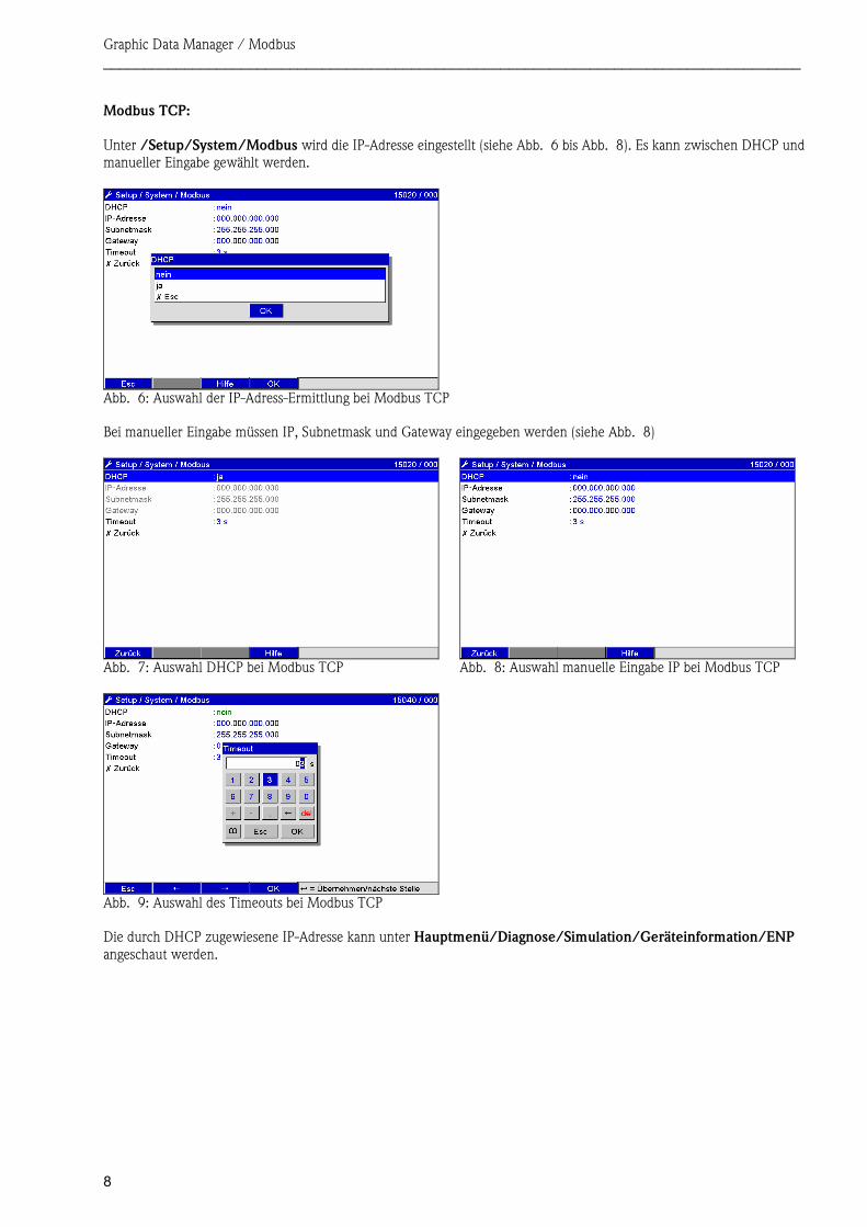
Modbus TCP: Unter /Setup/System/Modbus wird die IP-Adresse eingestellt (siehe Abb. 6 bis Abb. 8). Es kann zwischen DHCP und manueller Eingabe gewählt werden.
Abb. 6: Auswahl der IP-Adress-Ermittlung bei Modbus TCP Bei manueller Eingabe müssen IP, Subnetmask und Gateway eingegeben werden (siehe Abb. 8)
Abb. 7: Auswahl DHCP bei Modbus TCP Abb. 8: Auswahl manuelle Eingabe IP bei Modbus TCP
Abb. 9: Auswahl des Timeouts bei Modbus TCP Die durch DHCP zugewiesene IP-Adresse kann unter Hauptmenü/Diagnose/Simulation/Geräteinformation/ENP angeschaut werden.
Graphic Data Manager / Modbus ______________________________________________________________________________________
9
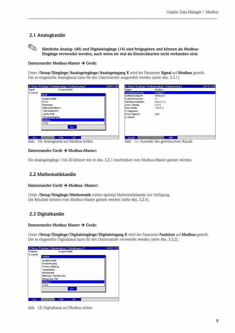
2.1 Analogkanäle
Sämtliche Analog- (40) und Digitaleingänge (14) sind freigegeben und können als Modbus- Eingänge verwendet werden, auch wenn sie real als Einsteckkarten nicht vorhanden sind.
Datentransfer Modbus-Master ���� Gerät: Unter /Setup/Eingänge/Analogeingänge/Analogeingang X wird der Parameter Signal auf Modbus gestellt. Der so eingestellte Analogkanal kann für den Datentransfer ausgewählt werden (siehe Abs. 3.2.1).
Abb. 10: Analogkanal auf Modbus stellen Abb. 11: Auswahl des gewünschten Kanals Datentransfer Gerät ���� Modbus-Master: Die Analogeingänge 1 bis 20 können wie in Abs. 3.2.1 beschrieben vom Modbus-Master gelesen werden.
2.2 Mathematikkanäle Datentransfer Gerät ���� Modbus -Master: Unter /Setup/Eingänge/Mathematik stehen optional Mathematikkanäle zur Verfügung. Die Resultate können vom Modbus-Master gelesen werden (siehe Abs. 3.2.4).
2.3 Digitalkanäle Datentransfer Modbus Master ���� Gerät: Unter /Setup/Eingänge/Digitaleingänge/Digitaleingang X wird der Parameter Funktion auf Modbus gestellt. Der so eingestellte Digitalkanal kann für den Datentransfer verwendet werden (siehe Abs. 3.2.2).
Abb. 12: Digitalkanal auf Modbus stellen
Graphic Data Manager / Modbus ______________________________________________________________________________________
10
Der vom Modbus-Master übertragene digitale Zustand hat im Gerät die gleiche Funktionalität wie der Zustand eines real vorhandenen Digitalkanals. Datentransfer Gerät ���� Modbus -Master: Steuereingang bzw. Ein/Aus-Meldung Der digitale Zustand des so eingestellten Digitalkanals kann vom Modbus-Master ausgelesen werden (siehe Abs. 3.2.5). Impulszähler bzw. Betriebszeit Der Gesamtzähler bzw. die Gesamtbetriebszeit des so eingestellten Digitalkanals kann vom Modbus-Master ausgelesen werden (siehe Abs. 3.2.5). Meldung + Betriebszeit Der digitale Zustand und der Gesamtzähler des so eingestellten Digitalkanals vom Modbus-Master ausgelesen werden (siehe Abs. 3.2.5).
Graphic Data Manager / Modbus ______________________________________________________________________________________
11
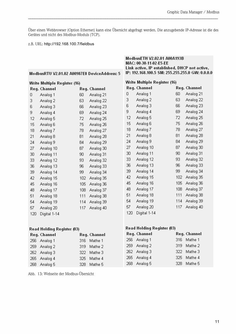
Über einen Webbrowser (Option Ethernet) kann eine Übersicht abgefragt werden. Die anzugebende IP-Adresse ist die des Gerätes und nicht des Modbus-Moduls (TCP). z.B. URL: http://192.168.100.7/fieldbus
Abb. 13: Webseite der Modbus-Übersicht
Graphic Data Manager / Modbus ______________________________________________________________________________________
12
3 Datenübertragung
3.1 Allgemeines Unterstützt werden die Funktionen 03: Read Holding Register und 16: Write Multiple Register.
Vom Modbus-Master zum Gerät können - Analogwerte (Momentanwerte) - digitale Zustände - Texte übertragen werden. Vom Gerät zum Modbus-Master können - Analogwerte (Momentanwerte) - Integrierte Analogwerte (Gesamtzähler) - Mathematikkanäle (Resultat: Zustand, Momentanwert, Betriebszeit, Gesamtzähler) - integrierte Mathematikkanäle (Gesamtzähler) - digitale Zustände - Impulszähler (Gesamtzähler) - Betriebszeiten übertragen werden.
Graphic Data Manager / Modbus ______________________________________________________________________________________
13
3.2 Adressierung Die Anfrage/Antwort-Beispiele beziehen sich auf Modbus RTU.
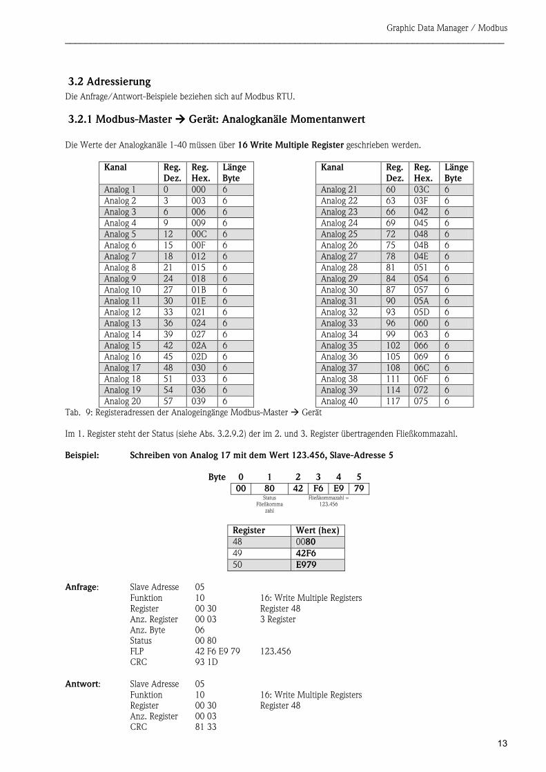
3.2.1 Modbus-Master ���� Gerät: Analogkanäle Momentanwert Die Werte der Analogkanäle 1-40 müssen über 16 Write Multiple Register geschrieben werden.
Kanal Reg. Dez.
Reg. Hex.
LängeByte
Kanal Reg. Dez.
Reg. Hex.
LängeByte
Analog 1 0 000 6 Analog 21 60 03C 6Analog 2 3 003 6 Analog 22 63 03F 6 Analog 3 6 006 6 Analog 23 66 042 6Analog 4 9 009 6 Analog 24 69 045 6 Analog 5 12 00C 6 Analog 25 72 048 6Analog 6 15 00F 6 Analog 26 75 04B 6 Analog 7 18 012 6 Analog 27 78 04E 6Analog 8 21 015 6 Analog 28 81 051 6 Analog 9 24 018 6 Analog 29 84 054 6Analog 10 27 01B 6 Analog 30 87 057 6 Analog 11 30 01E 6 Analog 31 90 05A 6Analog 12 33 021 6 Analog 32 93 05D 6 Analog 13 36 024 6 Analog 33 96 060 6Analog 14 39 027 6 Analog 34 99 063 6 Analog 15 42 02A 6 Analog 35 102 066 6Analog 16 45 02D 6 Analog 36 105 069 6 Analog 17 48 030 6 Analog 37 108 06C 6Analog 18 51 033 6 Analog 38 111 06F 6 Analog 19 54 036 6 Analog 39 114 072 6Analog 20 57 039 6 Analog 40 117 075 6
Im 1. Register steht der Status (siehe Abs. 3.2.9.2) der im 2. und 3. Register übertragenden Fließkommazahl. Beispiel: Schreiben von Analog 17 mit dem Wert 123.456, Slave-Adresse 5
Byte 0 1 2 3 4 500 80 42 F6 E9 79
Status Fließkomma
zahl
Fließkommazahl = 123.456
Register Wert (hex)48 0080 49 42F6 50 E979
Anfrage: Slave Adresse 05 Funktion 10 16: Write Multiple Registers Register 00 30 Register 48 Anz. Register 00 03 3 Register Anz. Byte 06 Status 00 80 FLP 42 F6 E9 79 123.456 CRC 93 1D
Antwort: Slave Adresse 05
Funktion 10 16: Write Multiple Registers Register 00 30 Register 48 Anz. Register 00 03 CRC 81 33
Tab. 9: Registeradressen der Analogeingänge Modbus-Master � Gerät
Graphic Data Manager / Modbus ______________________________________________________________________________________
14
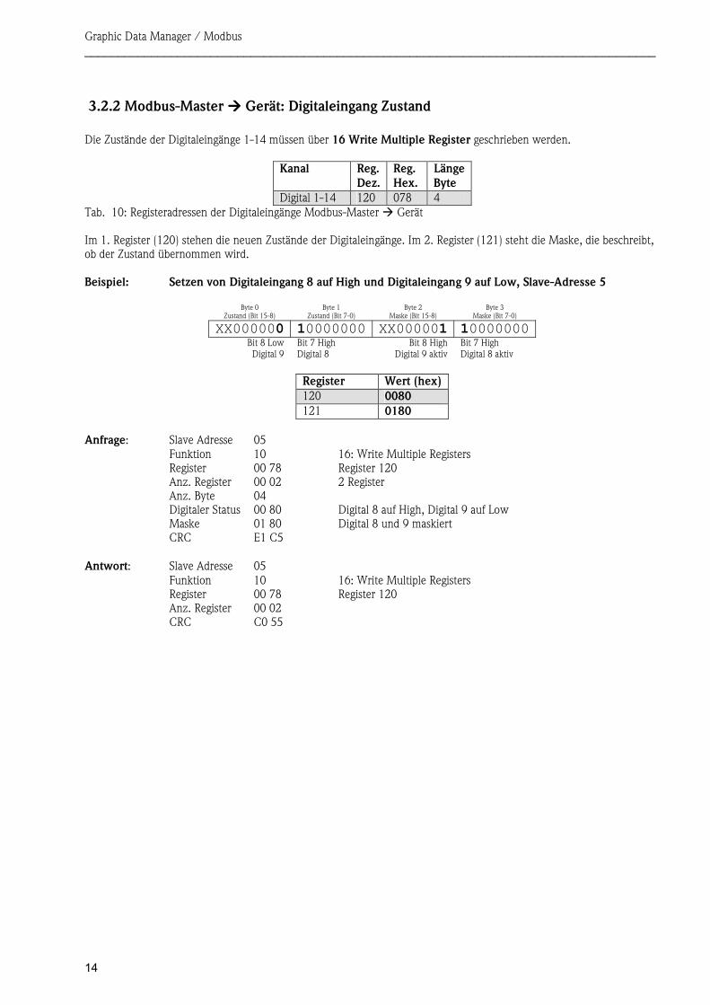
3.2.2 Modbus-Master ���� Gerät: Digitaleingang Zustand Die Zustände der Digitaleingänge 1-14 müssen über 16 Write Multiple Register geschrieben werden.
Kanal Reg. Dez.
Reg. Hex.
LängeByte
Digital 1-14 120 078 4
Im 1. Register (120) stehen die neuen Zustände der Digitaleingänge. Im 2. Register (121) steht die Maske, die beschreibt, ob der Zustand übernommen wird. Beispiel: Setzen von Digitaleingang 8 auf High und Digitaleingang 9 auf Low, Slave-Adresse 5
Byte 0 Zustand (Bit 15-8)
Byte 1 Zustand (Bit 7-0)
Byte 2 Maske (Bit 15-8)
Byte 3 Maske (Bit 7-0)
XX000000 10000000 XX000001 10000000Bit 8 Low Digital 9
Bit 7 High Digital 8
Bit 8 HighDigital 9 aktiv
Bit 7 High Digital 8 aktiv
Register Wert (hex)120 0080 121 0180
Anfrage: Slave Adresse 05 Funktion 10 16: Write Multiple Registers Register 00 78 Register 120 Anz. Register 00 02 2 Register Anz. Byte 04 Digitaler Status 00 80 Digital 8 auf High, Digital 9 auf Low Maske 01 80 Digital 8 und 9 maskiert CRC E1 C5
Antwort: Slave Adresse 05
Funktion 10 16: Write Multiple Registers Register 00 78 Register 120 Anz. Register 00 02 CRC C0 55
Tab. 10: Registeradressen der Digitaleingänge Modbus-Master � Gerät
Graphic Data Manager / Modbus ______________________________________________________________________________________
15
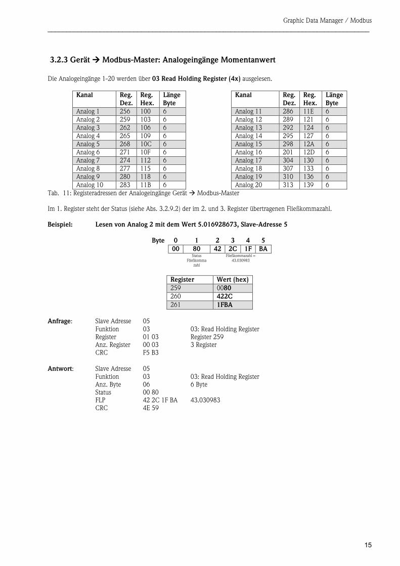
3.2.3 Gerät ���� Modbus-Master: Analogeingänge Momentanwert Die Analogeingänge 1-20 werden über 03 Read Holding Register (4x) ausgelesen.
Kanal Reg. Dez.
Reg. Hex.
LängeByte
Kanal Reg. Dez.
Reg. Hex.
LängeByte
Analog 1 256 100 6 Analog 11 286 11E 6Analog 2 259 103 6 Analog 12 289 121 6 Analog 3 262 106 6 Analog 13 292 124 6Analog 4 265 109 6 Analog 14 295 127 6 Analog 5 268 10C 6 Analog 15 298 12A 6Analog 6 271 10F 6 Analog 16 201 12D 6 Analog 7 274 112 6 Analog 17 304 130 6Analog 8 277 115 6 Analog 18 307 133 6 Analog 9 280 118 6 Analog 19 310 136 6Analog 10 283 11B 6 Analog 20 313 139 6
Im 1. Register steht der Status (siehe Abs. 3.2.9.2) der im 2. und 3. Register übertragenen Fließkommazahl. Beispiel: Lesen von Analog 2 mit dem Wert 5.016928673, Slave-Adresse 5
Byte 0 1 2 3 4 500 80 42 2C 1F BA
Status Fließkomma
zahl
Fließkommazahl = 43.030983
Register Wert (hex)259 0080 260 422C 261 1FBA
Anfrage: Slave Adresse 05 Funktion 03 03: Read Holding Register Register 01 03 Register 259 Anz. Register 00 03 3 Register CRC F5 B3
Antwort: Slave Adresse 05
Funktion 03 03: Read Holding Register Anz. Byte 06 6 Byte Status 00 80 FLP 42 2C 1F BA 43.030983 CRC 4E 59
Tab. 11: Registeradressen der Analogeingänge Gerät � Modbus-Master
Graphic Data Manager / Modbus ______________________________________________________________________________________
16
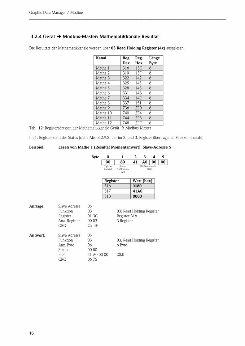
3.2.4 Gerät ���� Modbus-Master: Mathematikkanäle Resultat Die Resultate der Mathematikkanäle werden über 03 Read Holding Register (4x) ausgelesen.
Kanal Reg. Dez.
Reg. Hex.
LängeByte
Mathe 1 316 13C 6Mathe 2 319 13F 6 Mathe 3 322 142 6Mathe 4 325 145 6 Mathe 5 328 148 6Mathe 6 331 14B 6 Mathe 7 334 14E 6Mathe 8 337 151 6 Mathe 9 736 2E0 6Mathe 10 740 2E4 6 Mathe 11 744 2E8 6Mathe 12 748 2EC 6
Im 1. Register steht der Status (siehe Abs. 3.2.9.2) der im 2. und 3. Register übertragenen Fließkommazahl. Beispiel: Lesen von Mathe 1 (Resultat Momentanwert), Slave-Adresse 5
Byte 0 1 2 3 4 500 80 41 A0 00 00
DigitalerZustand
Status Fließkomma
zahl
Fließkommazahl = 20.0
Register Wert (hex)316 0080 317 41A0 318 0000
Anfrage: Slave Adresse 05 Funktion 03 03: Read Holding Register Register 01 3C Register 316 Anz. Register 00 03 3 Register CRC C5 BF
Antwort: Slave Adresse 05
Funktion 03 03: Read Holding Register Anz. Byte 06 6 Byte Status 00 80 FLP 41 A0 00 00 20.0 CRC 06 75
Tab. 12: Registeradressen der Mathematikkanäle Gerät � Modbus-Master
Graphic Data Manager / Modbus ______________________________________________________________________________________
17
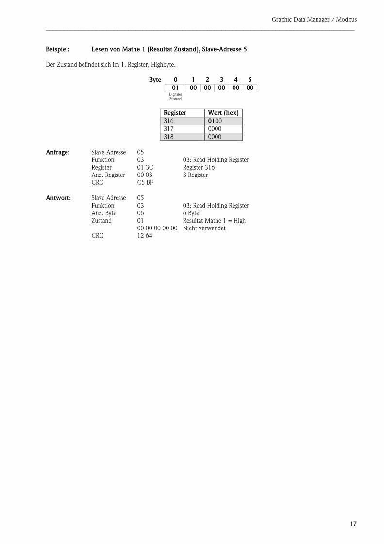
Beispiel: Lesen von Mathe 1 (Resultat Zustand), Slave-Adresse 5 Der Zustand befindet sich im 1. Register, Highbyte.
Byte 0 1 2 3 4 501 00 00 00 00 00
Digitaler Zustand
Register Wert (hex)316 0100 317 0000 318 0000
Anfrage: Slave Adresse 05 Funktion 03 03: Read Holding Register Register 01 3C Register 316 Anz. Register 00 03 3 Register CRC C5 BF
Antwort: Slave Adresse 05
Funktion 03 03: Read Holding Register Anz. Byte 06 6 Byte Zustand 01 Resultat Mathe 1 = High 00 00 00 00 00 Nicht verwendet CRC 12 64
Graphic Data Manager / Modbus ______________________________________________________________________________________
18
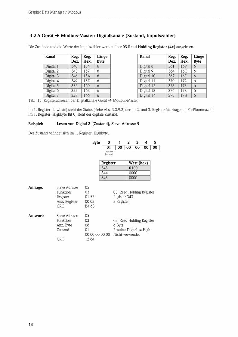
3.2.5 Gerät ���� Modbus-Master: Digitalkanäle (Zustand, Impulszähler) Die Zustände und die Werte der Impulszähler werden über 03 Read Holding Register (4x) ausgelesen.
Kanal Reg. Dez.
Reg. Hex.
LängeByte
Kanal Reg. Dez.
Reg. Hex.
LängeByte
Digital 1 340 154 6 Digital 8 361 169 6Digital 2 343 157 6 Digital 9 364 16C 6 Digital 3 346 15A 6 Digital 10 367 16F 6Digital 4 349 15D 6 Digital 11 370 172 6 Digital 5 352 160 6 Digital 12 373 175 6Digital 6 355 163 6 Digital 13 376 178 6 Digital 7 358 166 6 Digital 14 379 17B 6
Im 1. Register (Lowbyte) steht der Status (siehe Abs. 3.2.9.2) der im 2. und 3. Register übertragenen Fließkommazahl. Im 1. Register (Highbyte Bit 0) steht der digitale Zustand. Beispiel: Lesen von Digital 2 (Zustand), Slave-Adresse 5 Der Zustand befindet sich im 1. Register, Highbyte.
Byte 0 1 2 3 4 501 00 00 00 00 00
Digitaler Zustand
Register Wert (hex)343 0100 344 0000 345 0000
Anfrage: Slave Adresse 05 Funktion 03 03: Read Holding Register Register 01 57 Register 343 Anz. Register 00 03 3 Register CRC B4 63
Antwort: Slave Adresse 05
Funktion 03 03: Read Holding Register Anz. Byte 06 6 Byte Zustand 01 Resultat Digital = High 00 00 00 00 00 Nicht verwendet CRC 12 64
Tab. 13: Registeradressen der Digitalkanäle Gerät � Modbus-Master
Graphic Data Manager / Modbus ______________________________________________________________________________________
19
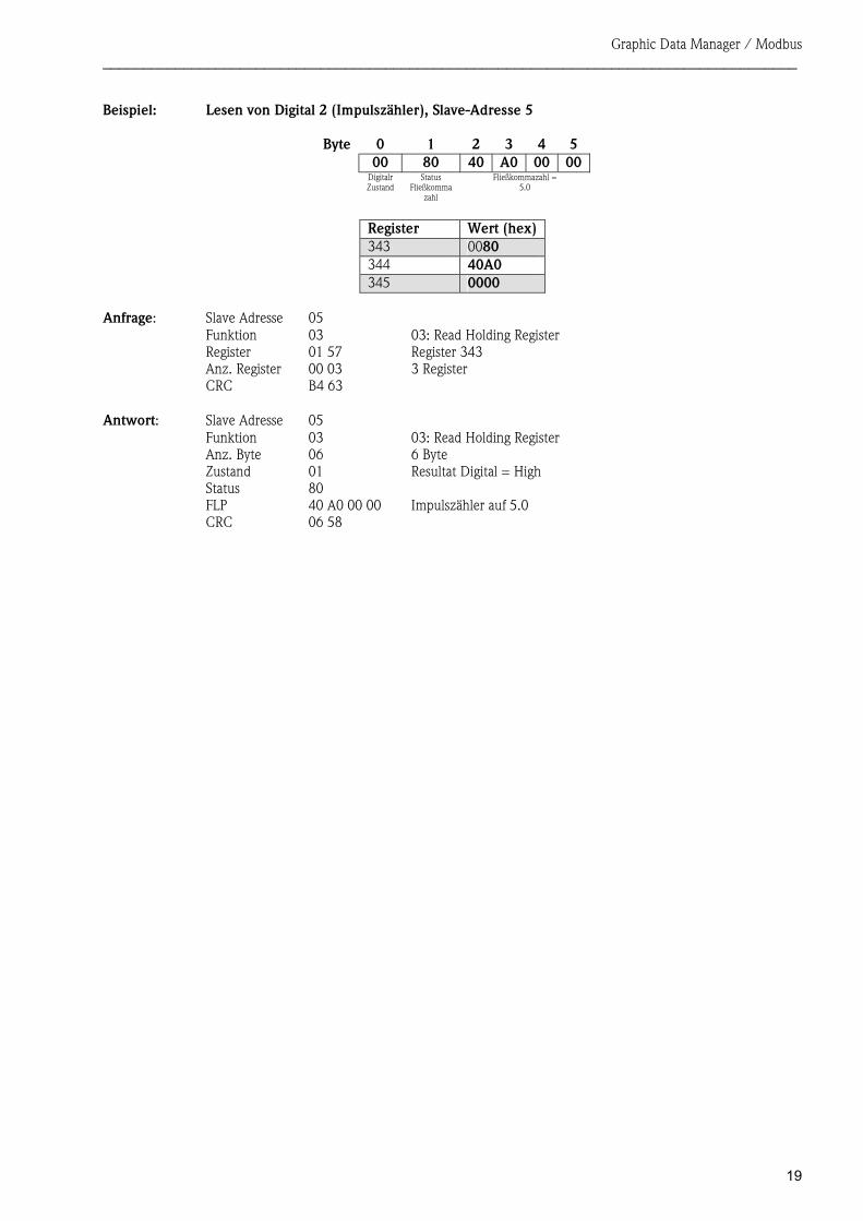
Beispiel: Lesen von Digital 2 (Impulszähler), Slave-Adresse 5
Byte 0 1 2 3 4 5 00 80 40 A0 00 00
DigitalrZustand
Status Fließkomma
zahl
Fließkommazahl = 5.0
Register Wert (hex)343 0080 344 40A0 345 0000
Anfrage: Slave Adresse 05 Funktion 03 03: Read Holding Register Register 01 57 Register 343 Anz. Register 00 03 3 Register CRC B4 63
Antwort: Slave Adresse 05
Funktion 03 03: Read Holding Register Anz. Byte 06 6 Byte Zustand 01 Resultat Digital = High Status 80 FLP 40 A0 00 00 Impulszähler auf 5.0 CRC 06 58
Graphic Data Manager / Modbus ______________________________________________________________________________________
20
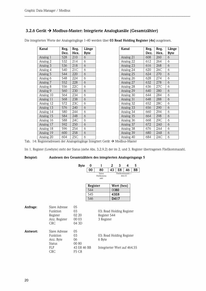
3.2.6 Gerät ���� Modbus-Master: Integrierte Analogkanäle (Gesamtzähler) Die integrierten Werte der Analogeingänge 1-40 werden über 03 Read Holding Register (4x) ausgelesen.
Kanal Reg. Dez.
Reg. Hex.
LängeByte
Kanal Reg. Dez.
Reg. Hex.
LängeByte
Analog 1 528 210 6 Analog 21 608 260 6Analog 2 532 214 6 Analog 22 612 264 6 Analog 3 536 218 6 Analog 23 616 268 6Analog 4 540 21C 6 Analog 24 620 26C 6 Analog 5 544 220 6 Analog 25 624 270 6Analog 6 548 224 6 Analog 26 628 274 6 Analog 7 552 228 6 Analog 27 632 278 6Analog 8 556 22C 6 Analog 28 636 27C 6 Analog 9 560 230 6 Analog 29 640 280 6Analog 10 564 234 6 Analog 30 644 284 6 Analog 11 568 238 6 Analog 31 648 288 6Analog 12 572 23C 6 Analog 32 652 28C 6 Analog 13 576 240 6 Analog 33 656 290 6Analog 14 580 244 6 Analog 34 660 294 6 Analog 15 584 248 6 Analog 35 664 298 6Analog 16 588 24C 6 Analog 36 668 29C 6 Analog 17 592 250 6 Analog 37 672 2A0 6Analog 18 596 254 6 Analog 38 676 2A4 6 Analog 19 600 258 6 Analog 39 680 2A8 6Analog 20 604 25C 6 Analog 40 684 2AC 6
Im 1. Register (Lowbyte) steht der Status (siehe Abs. 3.2.9.2) der im 2. und 3. Register übertragenen Fließkommazahl. Beispiel: Auslesen des Gesamtzählers des integrierten Analogeingangs 5
Byte 0 1 2 3 4 500 80 43 E8 46 BB
Status Fließkomma
zahl
Fließkommazahl = 464.55
Register Wert (hex)544 0080 545 43E8 546 D417
Anfrage: Slave Adresse 05 Funktion 03 03: Read Holding Register Register 02 20 Register 544 Anz. Register 00 03 3 Register CRC 04 3D
Antwort: Slave Adresse 05 Funktion 03 03: Read Holding Register Anz. Byte 06 6 Byte Status 00 80 FLP 43 E8 46 BB Integrierter Wert auf 464.55 CRC F5 C8
Tab. 14: Registeradressen der Analogeingänge Integriert Gerät � Modbus-Master
Graphic Data Manager / Modbus ______________________________________________________________________________________
21
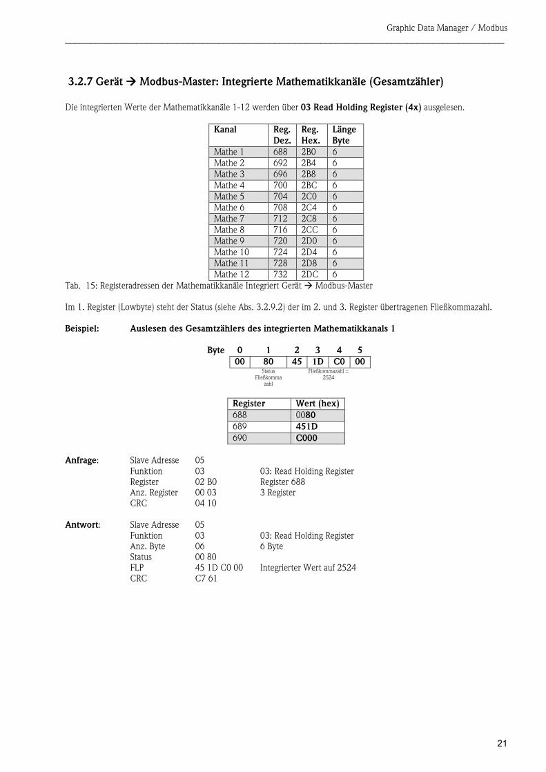
3.2.7 Gerät ���� Modbus-Master: Integrierte Mathematikkanäle (Gesamtzähler) Die integrierten Werte der Mathematikkanäle 1-12 werden über 03 Read Holding Register (4x) ausgelesen.
Kanal Reg. Dez.
Reg. Hex.
LängeByte
Mathe 1 688 2B0 6Mathe 2 692 2B4 6 Mathe 3 696 2B8 6Mathe 4 700 2BC 6 Mathe 5 704 2C0 6Mathe 6 708 2C4 6 Mathe 7 712 2C8 6Mathe 8 716 2CC 6 Mathe 9 720 2D0 6Mathe 10 724 2D4 6 Mathe 11 728 2D8 6Mathe 12 732 2DC 6
Im 1. Register (Lowbyte) steht der Status (siehe Abs. 3.2.9.2) der im 2. und 3. Register übertragenen Fließkommazahl. Beispiel: Auslesen des Gesamtzählers des integrierten Mathematikkanals 1
Byte 0 1 2 3 4 500 80 45 1D C0 00
Status Fließkomma
zahl
Fließkommazahl = 2524
Register Wert (hex)688 0080 689 451D 690 C000
Anfrage: Slave Adresse 05 Funktion 03 03: Read Holding Register Register 02 B0 Register 688 Anz. Register 00 03 3 Register CRC 04 10
Antwort: Slave Adresse 05 Funktion 03 03: Read Holding Register Anz. Byte 06 6 Byte Status 00 80 FLP 45 1D C0 00 Integrierter Wert auf 2524 CRC C7 61
Tab. 15: Registeradressen der Mathematikkanäle Integriert Gerät � Modbus-Master
Graphic Data Manager / Modbus ______________________________________________________________________________________
22
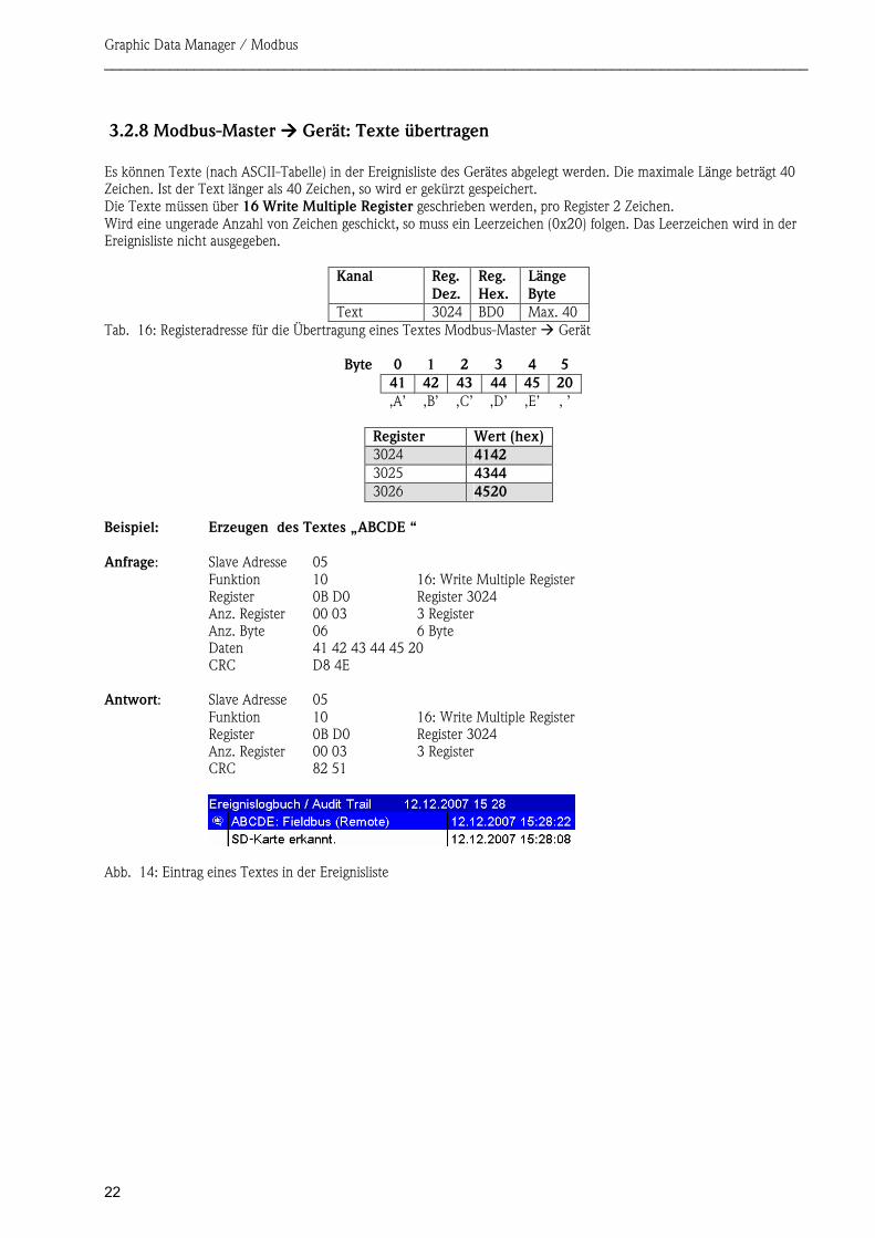
3.2.8 Modbus-Master ���� Gerät: Texte übertragen Es können Texte (nach ASCII-Tabelle) in der Ereignisliste des Gerätes abgelegt werden. Die maximale Länge beträgt 40 Zeichen. Ist der Text länger als 40 Zeichen, so wird er gekürzt gespeichert. Die Texte müssen über 16 Write Multiple Register geschrieben werden, pro Register 2 Zeichen. Wird eine ungerade Anzahl von Zeichen geschickt, so muss ein Leerzeichen (0x20) folgen. Das Leerzeichen wird in der Ereignisliste nicht ausgegeben.
Kanal Reg. Dez.
Reg. Hex.
Länge Byte
Text 3024 BD0 Max. 40
Byte 0 1 2 3 4 5 41 42 43 44 45 20
‚A’ ‚B’ ‚C’ ‚D’ ‚E’ ‚ ’
Register Wert (hex)3024 4142 3025 4344 3026 4520
Beispiel: Erzeugen des Textes „ABCDE “ Anfrage: Slave Adresse 05
Funktion 10 16: Write Multiple Register Register 0B D0 Register 3024 Anz. Register 00 03 3 Register Anz. Byte 06 6 Byte Daten 41 42 43 44 45 20 CRC D8 4E
Antwort: Slave Adresse 05 Funktion 10 16: Write Multiple Register Register 0B D0 Register 3024 Anz. Register 00 03 3 Register CRC 82 51
Tab. 16: Registeradresse für die Übertragung eines Textes Modbus-Master � Gerät
Abb. 14: Eintrag eines Textes in der Ereignisliste
Graphic Data Manager / Modbus ______________________________________________________________________________________
23
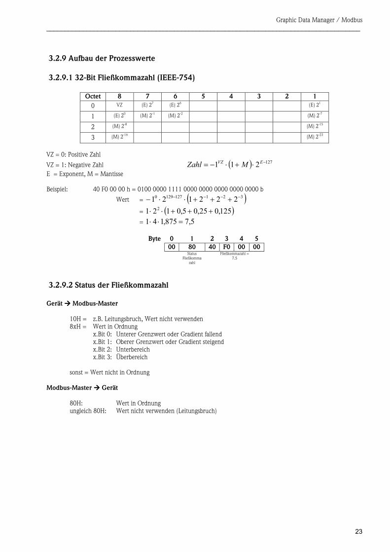
3.2.9 Aufbau der Prozesswerte
3.2.9.1 32-Bit Fließkommazahl (IEEE-754)
Octet 8 7 6 5 4 3 2 1 0 VZ (E) 27 (E) 26 (E) 21
1 (E) 20 (M) 2-1 (M) 2-2 (M) 2-7
2 (M) 2-8 (M) 2-15
3 (M) 2-16 (M) 2-23
VZ = 0: Positive Zahl
VZ = 1: Negative Zahl ( ) 127211 −⋅+⋅−= EVZ MZahlE = Exponent, M = Mantisse Beispiel: 40 F0 00 00 h = 0100 0000 1111 0000 0000 0000 0000 0000 b
Wert = ( )3211271290 222121 −−−− +++⋅⋅−= ( )125,025,05,0121 2 +++⋅⋅= 5,7875,141 =⋅⋅
Byte 0 1 2 3 4 5 00 80 40 F0 00 00
Status Fließkomma
zahl
Fließkommazahl = 7.5
3.2.9.2 Status der Fließkommazahl Gerät ���� Modbus-Master
10H = z.B. Leitungsbruch, Wert nicht verwenden 8xH = Wert in Ordnung
x.Bit 0: Unterer Grenzwert oder Gradient fallend x.Bit 1: Oberer Grenzwert oder Gradient steigend x.Bit 2: Unterbereich x.Bit 3: Überbereich
sonst = Wert nicht in Ordnung
Modbus-Master ���� Gerät
80H: Wert in Ordnung ungleich 80H: Wert nicht verwenden (Leitungsbruch)
Graphic Data Manager / Modbus ______________________________________________________________________________________
24
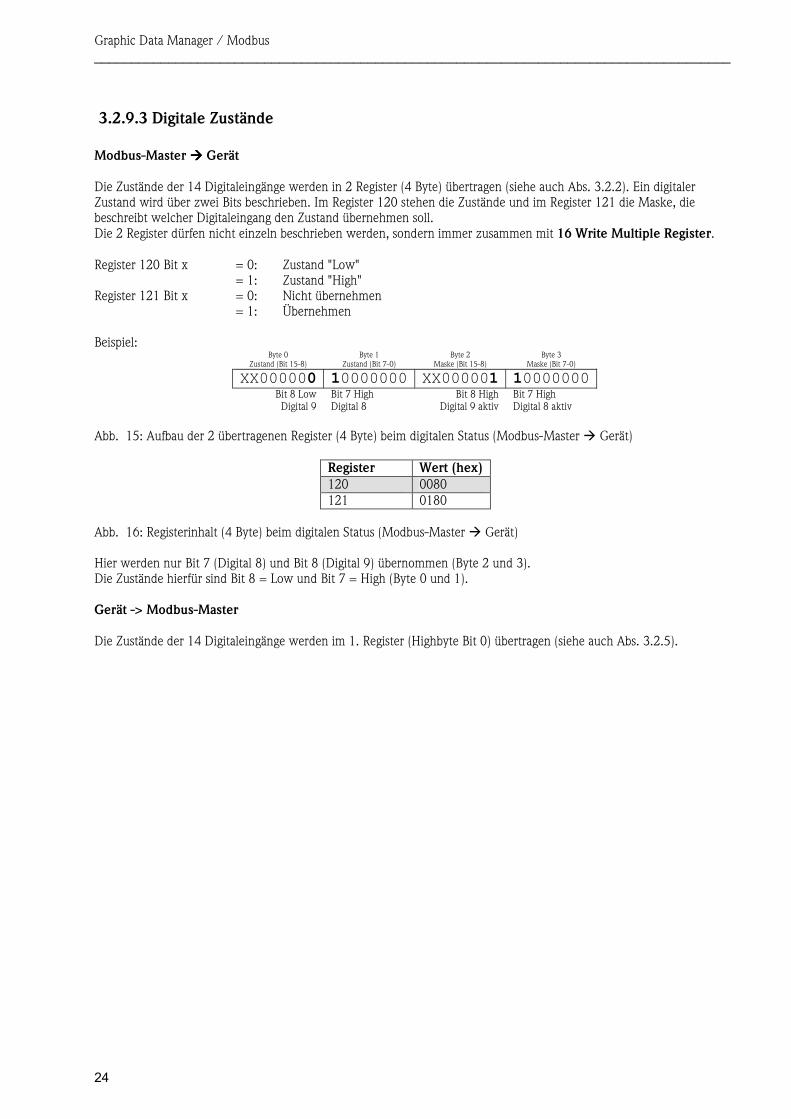
3.2.9.3 Digitale Zustände Modbus-Master ���� Gerät Die Zustände der 14 Digitaleingänge werden in 2 Register (4 Byte) übertragen (siehe auch Abs. 3.2.2). Ein digitaler Zustand wird über zwei Bits beschrieben. Im Register 120 stehen die Zustände und im Register 121 die Maske, die beschreibt welcher Digitaleingang den Zustand übernehmen soll. Die 2 Register dürfen nicht einzeln beschrieben werden, sondern immer zusammen mit 16 Write Multiple Register.
Register 120 Bit x = 0: Zustand "Low" = 1: Zustand "High" Register 121 Bit x = 0: Nicht übernehmen = 1: Übernehmen Beispiel:
Byte 0 Zustand (Bit 15-8)
Byte 1 Zustand (Bit 7-0)
Byte 2 Maske (Bit 15-8)
Byte 3 Maske (Bit 7-0)
XX000000 10000000 XX000001 10000000Bit 8 Low Digital 9
Bit 7 High Digital 8
Bit 8 HighDigital 9 aktiv
Bit 7 High Digital 8 aktiv
Register Wert (hex)120 0080 121 0180
Hier werden nur Bit 7 (Digital 8) und Bit 8 (Digital 9) übernommen (Byte 2 und 3). Die Zustände hierfür sind Bit 8 = Low und Bit 7 = High (Byte 0 und 1). Gerät -> Modbus-Master Die Zustände der 14 Digitaleingänge werden im 1. Register (Highbyte Bit 0) übertragen (siehe auch Abs. 3.2.5).
Abb. 15: Aufbau der 2 übertragenen Register (4 Byte) beim digitalen Status (Modbus-Master � Gerät)
Abb. 16: Registerinhalt (4 Byte) beim digitalen Status (Modbus-Master � Gerät)
Graphic Data Manager / Modbus ______________________________________________________________________________________
25
4 Abkürzungsverzeichnis/Begriffserklärungen Modbus-Modul: Das Steckmodul Modbus RTU Slave oder Modbus ETH Slave, das in der Rückwand des Gerätes
eingesteckt ist Modbus-Master: Alle Gerätschaften wie SPS, PLC, PC-Steckkarten, die eine Modbus-Master-Funktion ausüben
5 Index
A
Analogkanal ...............................................................9
Anschlüsse ...............................................................4, 5 Ausgänge ......................................................................9
B
Baudrate .......................................................................6
D
Datenübertragung .......................................................12 Digitale Zustände ........................................................24
E
Eingänge .......................................................................9
F
Funktion .......................................................................6
G
Gleitpunktzahl ............................................................23
L
LED, Status ..............................................................4, 5 LED,Betriebsmodus.................................................4, 5
M
Mathematikkanal ..........................................................9
S
Status Gleitpunktzahl ..................................................23

Graphic Data Manager / Modbus ______________________________________________________________________________________
26
Table of contents: 1 General information ................................................................................................................................ 27
1.1 Requirements ...................................................................................................................................................27 1.2 Scope of delivery...............................................................................................................................................27 1.3 Modbus RTU plug-in module ............................................................................................................................27
1.3.1 Connections...............................................................................................................................................27 1.3.2 Communication LED..................................................................................................................................27 1.3.3 Status LED.................................................................................................................................................27 1.3.4 Modbus RTU connector (DB9F)..................................................................................................................28
1.4 Modbus TCP plug-in module.............................................................................................................................28 1.4.1 Connections...............................................................................................................................................28 1.4.2 Network status LED ...................................................................................................................................28 1.4.3 Status LED.................................................................................................................................................29 1.4.4 Link LED ...................................................................................................................................................29
1.5 Functional description .......................................................................................................................................29 1.6 Checking whether the Modbus module is present ..............................................................................................29
2 Settings in the Setup ................................................................................................................................ 30 2.1 Analog channels................................................................................................................................................32 2.2 Mathematics channels.......................................................................................................................................32 2.3 Digital channels ................................................................................................................................................32
3 Data transmission.................................................................................................................................... 35 3.1 General information ..........................................................................................................................................35 3.2 Addressing........................................................................................................................................................35
3.2.1 Modbus master � Device: Analog channels instantaneous value..................................................................35 3.2.2 Modbus master � Device: Digital input status ............................................................................................36 3.2.3 Device � Modbus master: Analog inputs instantaneous value .....................................................................37 3.2.4 Device � Modbus master: Maths channels result........................................................................................38 3.2.5 Device � Modbus master: Digital channels (Status, pulse counter) ..............................................................39 3.2.6 Device � Modbus master: Integrated analog channels (Counter) .................................................................42 3.2.7 Device � Modbus master: Integrated maths channels (Counter)..................................................................43 3.2.8 Modbus master � Device: Transfer text .....................................................................................................44 3.2.9 Structure of the process values....................................................................................................................45
4 List of abbreviations/explanation of terms ............................................................................................... 47 5 Index ...................................................................................................................................................... 47
Graphic Data Manager / Modbus ______________________________________________________________________________________
27
1 General information Please note the following pictograms:
Note: Suggestions for safe commissioning
Caution: Failure to observe instructions can cause damage to the device or lead to malfunction!
1.1 Requirements The Modbus module can only be used as of device firmware version V1.02.00 in conjunction with PC software version 1.23.1.0 and higher. The maths channels 9 to 12 are only supported as of device firmware version V1.10.00 Option „Energy“.
1.2 Scope of delivery Device with integrated Modbus module. These Operating Instructions can be found on the Doc-CD supplied.
1.3 Modbus RTU plug-in module
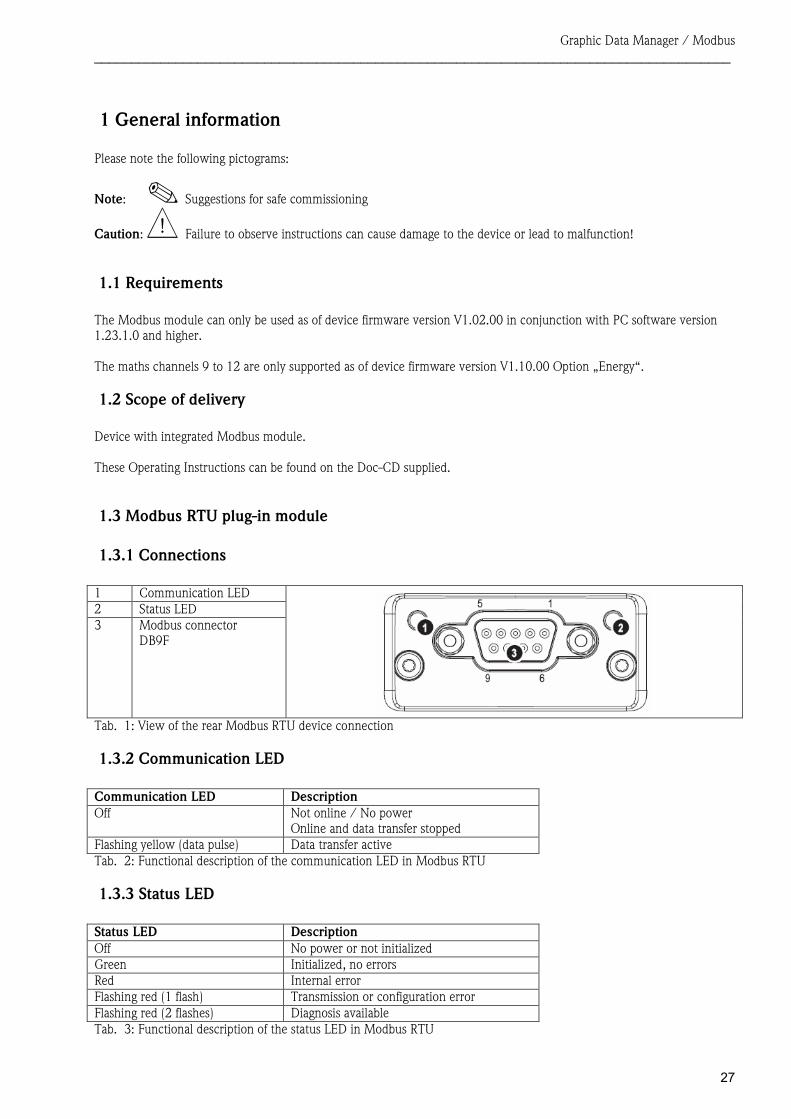
1.3.1 Connections 1 Communication LED 2 Status LED 3 Modbus connector
DB9F
1.3.2 Communication LED Communication LED Description Off Not online / No power
Online and data transfer stopped Flashing yellow (data pulse) Data transfer active
1.3.3 Status LED Status LED Description Off No power or not initialized Green Initialized, no errors Red Internal error Flashing red (1 flash) Transmission or configuration error Flashing red (2 flashes) Diagnosis available
Tab. 1: View of the rear Modbus RTU device connection
Tab. 2: Functional description of the communication LED in Modbus RTU
Tab. 3: Functional description of the status LED in Modbus RTU
Graphic Data Manager / Modbus ______________________________________________________________________________________
28
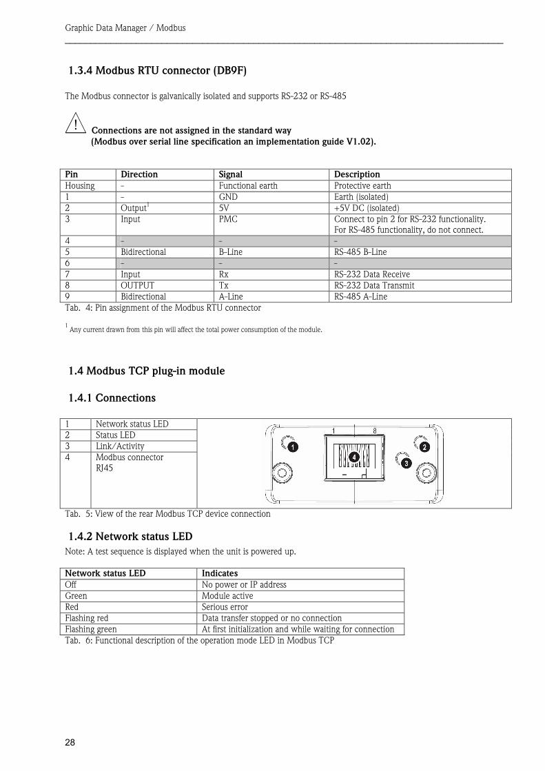
1.3.4 Modbus RTU connector (DB9F) The Modbus connector is galvanically isolated and supports RS-232 or RS-485
Connections are not assigned in the standard way (Modbus over serial line specification an implementation guide V1.02).
Pin Direction Signal Description Housing - Functional earth Protective earth 1 - GND Earth (isolated) 2 Output1 5V +5V DC (isolated) 3 Input PMC Connect to pin 2 for RS-232 functionality.
For RS-485 functionality, do not connect. 4 - - -5 Bidirectional B-Line RS-485 B-Line 6 - - -7 Input Rx RS-232 Data Receive 8 OUTPUT Tx RS-232 Data Transmit 9 Bidirectional A-Line RS-485 A-Line
1Any current drawn from this pin will affect the total power consumption of the module.
1.4 Modbus TCP plug-in module
1.4.1 Connections 1 Network status LED 2 Status LED 3 Link/Activity 4 Modbus connector
RJ45
1.4.2 Network status LED Note: A test sequence is displayed when the unit is powered up. Network status LED Indicates Off No power or IP address Green Module active Red Serious error Flashing red Data transfer stopped or no connection Flashing green At first initialization and while waiting for connection
Tab. 4: Pin assignment of the Modbus RTU connector
Tab. 5: View of the rear Modbus TCP device connection
Tab. 6: Functional description of the operation mode LED in Modbus TCP
Graphic Data Manager / Modbus ______________________________________________________________________________________
29
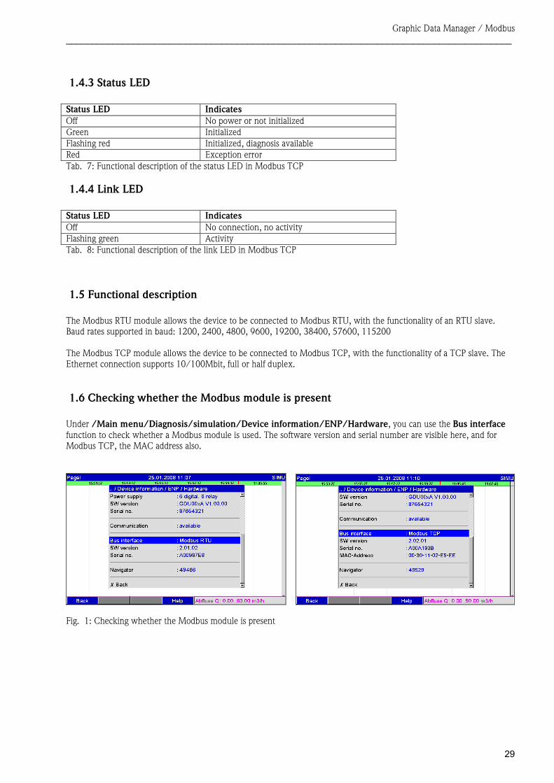
1.4.3 Status LED Status LED Indicates Off No power or not initialized Green Initialized Flashing red Initialized, diagnosis available Red Exception error
1.4.4 Link LED Status LED Indicates Off No connection, no activity Flashing green Activity
1.5 Functional description The Modbus RTU module allows the device to be connected to Modbus RTU, with the functionality of an RTU slave. Baud rates supported in baud: 1200, 2400, 4800, 9600, 19200, 38400, 57600, 115200 The Modbus TCP module allows the device to be connected to Modbus TCP, with the functionality of a TCP slave. The Ethernet connection supports 10/100Mbit, full or half duplex.
1.6 Checking whether the Modbus module is present Under /Main menu/Diagnosis/simulation/Device information/ENP/Hardware, you can use the Bus interface function to check whether a Modbus module is used. The software version and serial number are visible here, and for Modbus TCP, the MAC address also.
Tab. 7: Functional description of the status LED in Modbus TCP
Tab. 8: Functional description of the link LED in Modbus TCP
Fig. 1: Checking whether the Modbus module is present
Graphic Data Manager / Modbus ______________________________________________________________________________________
30
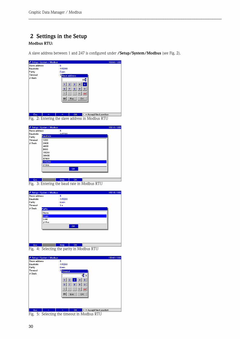
2 Settings in the Setup Modbus RTU: A slave address between 1 and 247 is configured under /Setup/System/Modbus (see Fig. 2).
Fig. 3: Entering the baud rate in Modbus RTU
Fig. 4: Selecting the parity in Modbus RTU
Fig. 5: Selecting the timeout in Modbus RTU
Fig. 2: Entering the slave address in Modbus RTU
Graphic Data Manager / Modbus ______________________________________________________________________________________
31
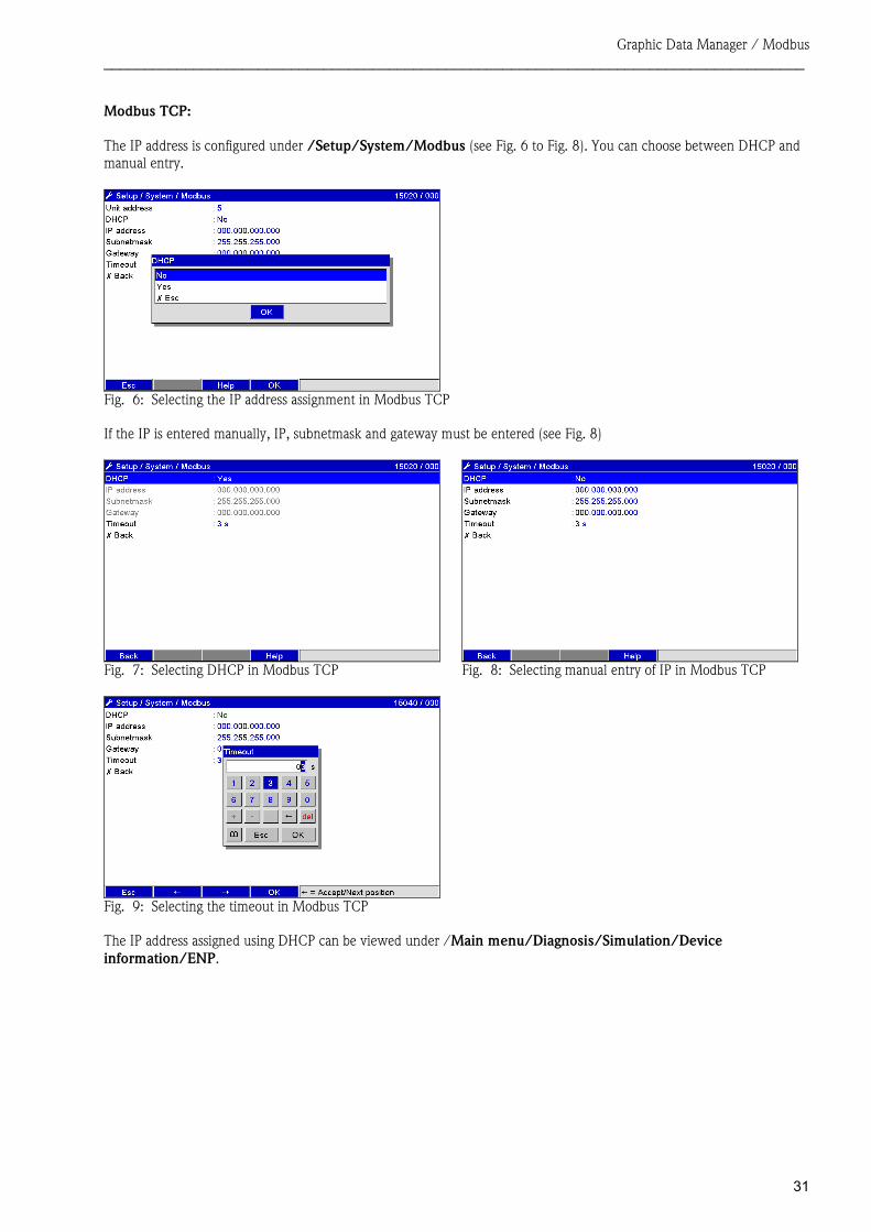
Modbus TCP: The IP address is configured under /Setup/System/Modbus (see Fig. 6 to Fig. 8). You can choose between DHCP and manual entry.
Fig. 6: Selecting the IP address assignment in Modbus TCP If the IP is entered manually, IP, subnetmask and gateway must be entered (see Fig. 8)
Fig. 7: Selecting DHCP in Modbus TCP Fig. 8: Selecting manual entry of IP in Modbus TCP
Fig. 9: Selecting the timeout in Modbus TCP The IP address assigned using DHCP can be viewed under /Main menu/Diagnosis/Simulation/Device information/ENP.
Graphic Data Manager / Modbus ______________________________________________________________________________________
32
2.1 Analog channels
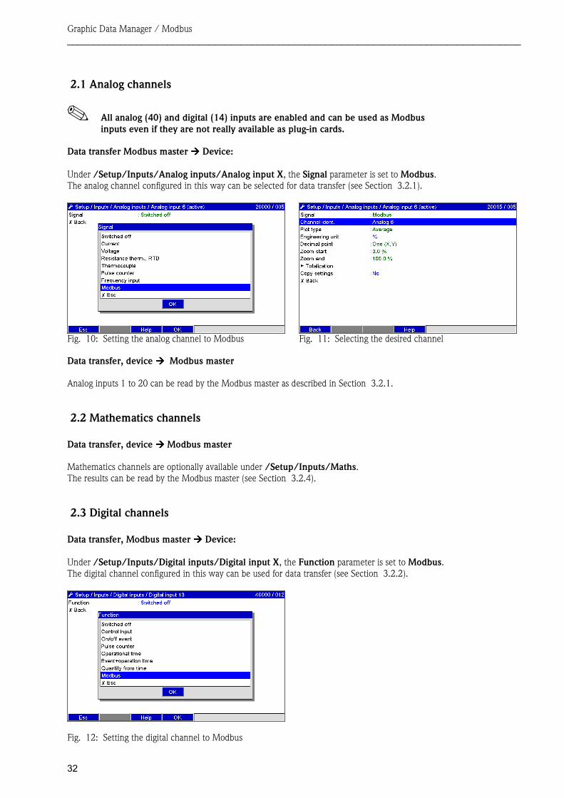
All analog (40) and digital (14) inputs are enabled and can be used as Modbus inputs even if they are not really available as plug-in cards.
Data transfer Modbus master ���� Device: Under /Setup/Inputs/Analog inputs/Analog input X, the Signal parameter is set to Modbus.The analog channel configured in this way can be selected for data transfer (see Section 3.2.1).
Fig. 10: Setting the analog channel to Modbus Fig. 11: Selecting the desired channel Data transfer, device ���� Modbus master Analog inputs 1 to 20 can be read by the Modbus master as described in Section 3.2.1.
2.2 Mathematics channels Data transfer, device ���� Modbus master Mathematics channels are optionally available under /Setup/Inputs/Maths.The results can be read by the Modbus master (see Section 3.2.4).
2.3 Digital channels Data transfer, Modbus master ���� Device: Under /Setup/Inputs/Digital inputs/Digital input X, the Function parameter is set to Modbus.The digital channel configured in this way can be used for data transfer (see Section 3.2.2).
Fig. 12: Setting the digital channel to Modbus

Graphic Data Manager / Modbus ______________________________________________________________________________________
33
The digital status transmitted by the Modbus master has the same functionality in the device as the status of a digital channel really available. Data transfer, device ���� Modbus master Control input or on/off event The digital status of the digital channel configured in this way can be read by the Modbus master (see Section 3.2.5). Pulse counter or operating time The counter or the total operating time of the digital channel configured in this way can be read by the Modbus master (see Section 3.2.5). Event+operation time The digital status and counter of the digital channel configured in this way can be read by the Modbus master (see Section 3.2.5).
Graphic Data Manager / Modbus ______________________________________________________________________________________
34
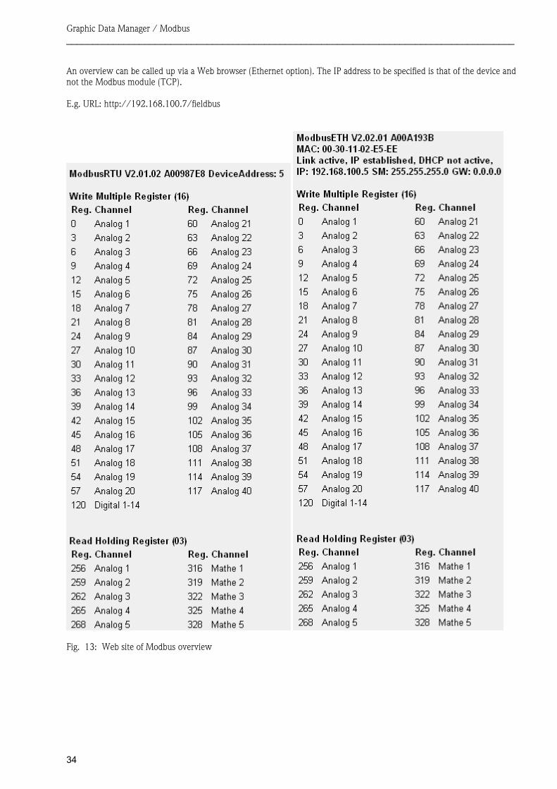
An overview can be called up via a Web browser (Ethernet option). The IP address to be specified is that of the device and not the Modbus module (TCP). E.g. URL: http://192.168.100.7/fieldbus
Fig. 13: Web site of Modbus overview
Graphic Data Manager / Modbus ______________________________________________________________________________________
35
3 Data transmission
3.1 General information
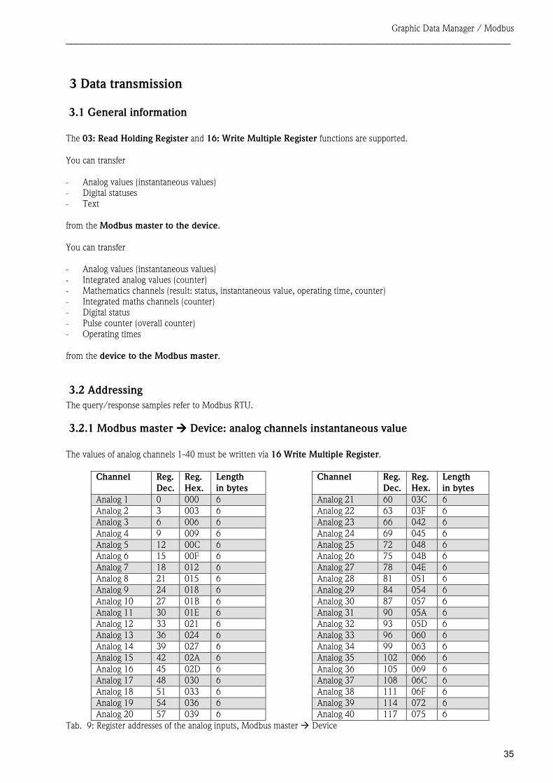
The 03: Read Holding Register and 16: Write Multiple Register functions are supported. You can transfer - Analog values (instantaneous values) - Digital statuses - Text from the Modbus master to the device.
You can transfer - Analog values (instantaneous values) - Integrated analog values (counter) - Mathematics channels (result: status, instantaneous value, operating time, counter) - Integrated maths channels (counter) - Digital status - Pulse counter (overall counter) - Operating times from the device to the Modbus master.
3.2 Addressing The query/response samples refer to Modbus RTU.
3.2.1 Modbus master ���� Device: analog channels instantaneous value The values of analog channels 1-40 must be written via 16 Write Multiple Register.
Channel Reg. Dec.
Reg. Hex.
Length in bytes
Channel Reg. Dec.
Reg. Hex.
Length in bytes
Analog 1 0 000 6 Analog 21 60 03C 6Analog 2 3 003 6 Analog 22 63 03F 6 Analog 3 6 006 6 Analog 23 66 042 6Analog 4 9 009 6 Analog 24 69 045 6 Analog 5 12 00C 6 Analog 25 72 048 6Analog 6 15 00F 6 Analog 26 75 04B 6 Analog 7 18 012 6 Analog 27 78 04E 6Analog 8 21 015 6 Analog 28 81 051 6 Analog 9 24 018 6 Analog 29 84 054 6Analog 10 27 01B 6 Analog 30 87 057 6 Analog 11 30 01E 6 Analog 31 90 05A 6Analog 12 33 021 6 Analog 32 93 05D 6 Analog 13 36 024 6 Analog 33 96 060 6Analog 14 39 027 6 Analog 34 99 063 6 Analog 15 42 02A 6 Analog 35 102 066 6Analog 16 45 02D 6 Analog 36 105 069 6 Analog 17 48 030 6 Analog 37 108 06C 6Analog 18 51 033 6 Analog 38 111 06F 6 Analog 19 54 036 6 Analog 39 114 072 6Analog 20 57 039 6 Analog 40 117 075 6
Tab. 9: Register addresses of the analog inputs, Modbus master � Device
Graphic Data Manager / Modbus ______________________________________________________________________________________
36
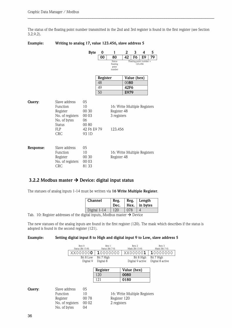
The status of the floating point number transmitted in the 2nd and 3rd register is found in the first register (see Section 3.2.9.2). Example: Writing to analog 17, value 123.456, slave address 5
Byte 0 1 2 3 4 500 80 42 F6 E9 79
Status floating point
number
Floating point number = 123.456
Register Value (hex) 48 0080 49 42F6 50 E979
Query: Slave address 05 Function 10 16: Write Multiple Registers Register 00 30 Register 48 No. of registers 00 03 3 registers No. of bytes 06 Status 00 80 FLP 42 F6 E9 79 123.456 CRC 93 1D
Response: Slave address 05 Function 10 16: Write Multiple Registers Register 00 30 Register 48 No. of registers 00 03 CRC 81 33
3.2.2 Modbus master ���� Device: digital input status The statuses of analog inputs 1-14 must be written via 16 Write Multiple Register.
Channel Reg. Dec.
Reg. Hex.
Length in bytes
Digital 1-14 120 078 4
The new statuses of the analog inputs are found in the first register (120). The mask which describes if the status is adopted is found in the second register (121). Example: Setting digital input 8 to High and digital input 9 to Low, slave address 5
Byte 0 Status (Bit 15-8)
Byte 1 Status (Bit 7-0)
Byte 2 Mask (Bit 15-8)
Byte 3 Mask (Bit 7-0)
XX000000 10000000 XX000001 10000000Bit 8 Low Digital 9
Bit 7 High Digital 8
Bit 8 HighDigital 9 active
Bit 7 High Digital 8 active
Register Value (hex) 120 0080 121 0180
Query: Slave address 05 Function 10 16: Write Multiple Registers Register 00 78 Register 120 No. of registers 00 02 2 registers No. of bytes 04
Tab. 10: Register addresses of the digital inputs, Modbus master � Device
Graphic Data Manager / Modbus ______________________________________________________________________________________
37
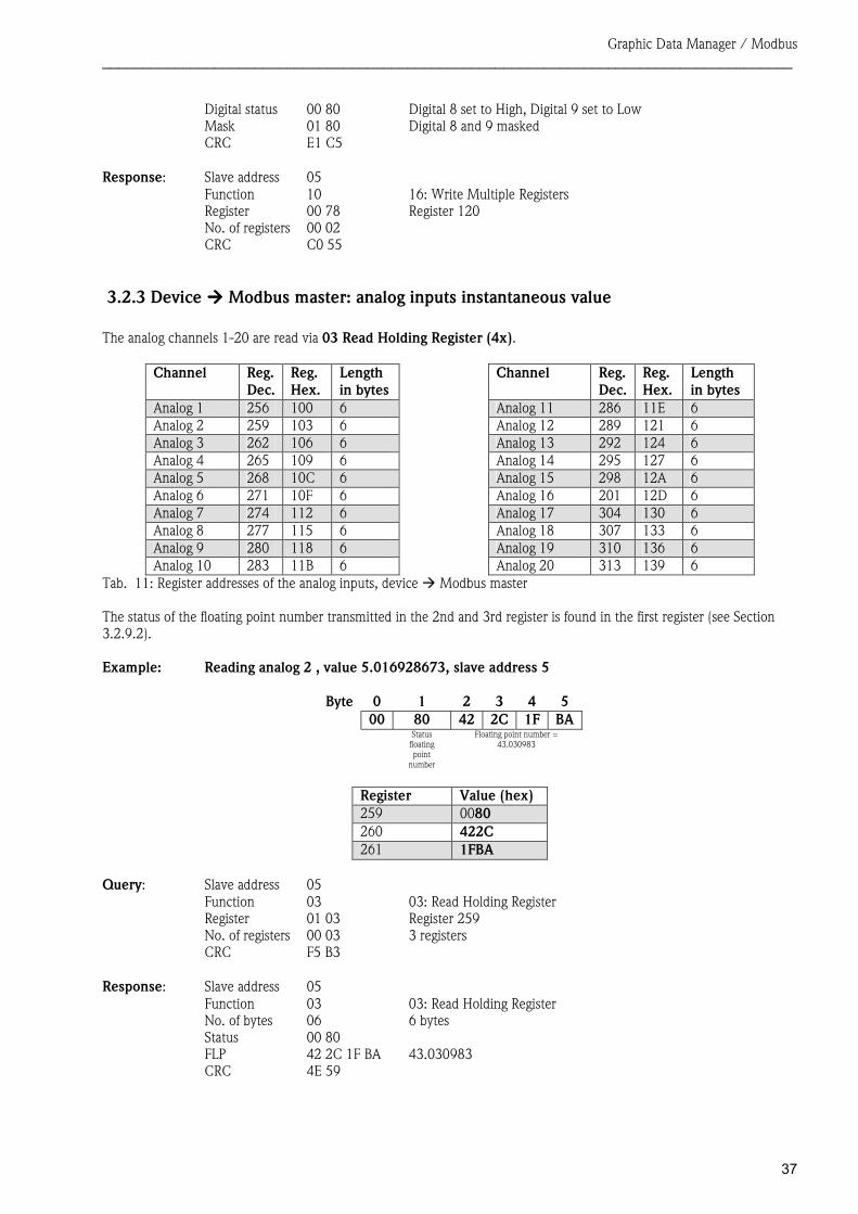
Digital status 00 80 Digital 8 set to High, Digital 9 set to Low Mask 01 80 Digital 8 and 9 masked CRC E1 C5
Response: Slave address 05
Function 10 16: Write Multiple Registers Register 00 78 Register 120 No. of registers 00 02 CRC C0 55
3.2.3 Device ���� Modbus master: analog inputs instantaneous value The analog channels 1-20 are read via 03 Read Holding Register (4x).
Channel Reg. Dec.
Reg. Hex.
Length in bytes
Channel Reg. Dec.
Reg. Hex.
Length in bytes
Analog 1 256 100 6 Analog 11 286 11E 6Analog 2 259 103 6 Analog 12 289 121 6 Analog 3 262 106 6 Analog 13 292 124 6Analog 4 265 109 6 Analog 14 295 127 6 Analog 5 268 10C 6 Analog 15 298 12A 6Analog 6 271 10F 6 Analog 16 201 12D 6 Analog 7 274 112 6 Analog 17 304 130 6Analog 8 277 115 6 Analog 18 307 133 6 Analog 9 280 118 6 Analog 19 310 136 6Analog 10 283 11B 6 Analog 20 313 139 6
The status of the floating point number transmitted in the 2nd and 3rd register is found in the first register (see Section 3.2.9.2). Example: Reading analog 2 , value 5.016928673, slave address 5
Byte 0 1 2 3 4 500 80 42 2C 1F BA
Status floating point
number
Floating point number = 43.030983
Register Value (hex) 259 0080 260 422C 261 1FBA
Query: Slave address 05 Function 03 03: Read Holding Register Register 01 03 Register 259 No. of registers 00 03 3 registers CRC F5 B3
Response: Slave address 05
Function 03 03: Read Holding Register No. of bytes 06 6 bytes Status 00 80 FLP 42 2C 1F BA 43.030983 CRC 4E 59
Tab. 11: Register addresses of the analog inputs, device � Modbus master
Graphic Data Manager / Modbus ______________________________________________________________________________________
38
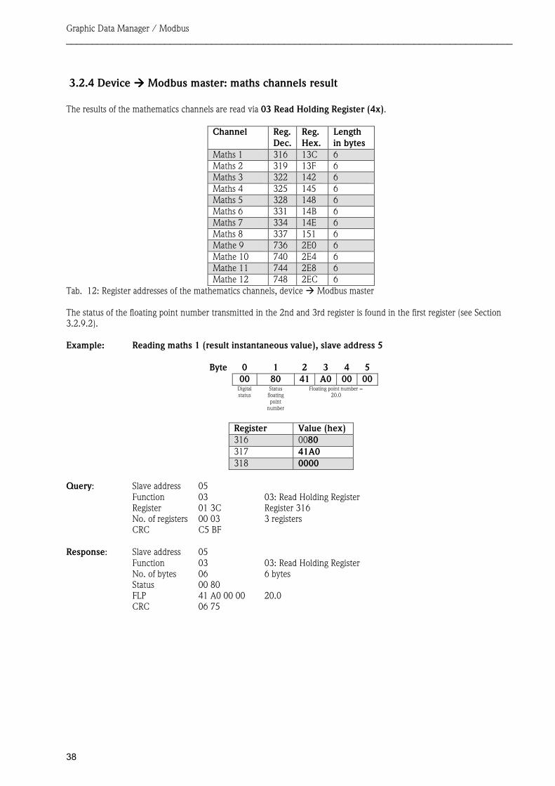
3.2.4 Device ���� Modbus master: maths channels result The results of the mathematics channels are read via 03 Read Holding Register (4x).
Channel Reg. Dec.
Reg. Hex.
Length in bytes
Maths 1 316 13C 6Maths 2 319 13F 6 Maths 3 322 142 6Maths 4 325 145 6 Maths 5 328 148 6Maths 6 331 14B 6 Maths 7 334 14E 6Maths 8 337 151 6 Mathe 9 736 2E0 6Mathe 10 740 2E4 6 Mathe 11 744 2E8 6Mathe 12 748 2EC 6
The status of the floating point number transmitted in the 2nd and 3rd register is found in the first register (see Section 3.2.9.2). Example: Reading maths 1 (result instantaneous value), slave address 5
Byte 0 1 2 3 4 500 80 41 A0 00 00
Digital status
Status floating point
number
Floating point number = 20.0
Register Value (hex) 316 0080 317 41A0 318 0000
Query: Slave address 05 Function 03 03: Read Holding Register Register 01 3C Register 316 No. of registers 00 03 3 registers CRC C5 BF
Response: Slave address 05
Function 03 03: Read Holding Register No. of bytes 06 6 bytes Status 00 80 FLP 41 A0 00 00 20.0 CRC 06 75
Tab. 12: Register addresses of the mathematics channels, device � Modbus master
Graphic Data Manager / Modbus ______________________________________________________________________________________
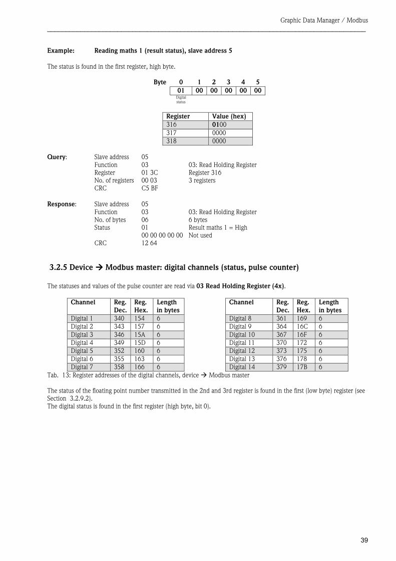
39
Example: Reading maths 1 (result status), slave address 5 The status is found in the first register, high byte.
Byte 0 1 2 3 4 501 00 00 00 00 00
Digital status
Register Value (hex) 316 0100 317 0000 318 0000
Query: Slave address 05 Function 03 03: Read Holding Register Register 01 3C Register 316 No. of registers 00 03 3 registers CRC C5 BF
Response: Slave address 05
Function 03 03: Read Holding Register No. of bytes 06 6 bytes Status 01 Result maths 1 = High 00 00 00 00 00 Not used CRC 12 64
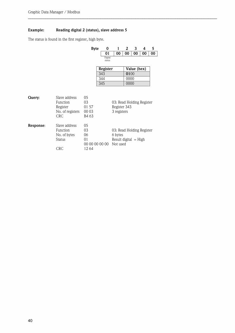
3.2.5 Device ���� Modbus master: digital channels (status, pulse counter) The statuses and values of the pulse counter are read via 03 Read Holding Register (4x).
Channel Reg. Dec.
Reg. Hex.
Length in bytes
Channel Reg. Dec.
Reg. Hex.
Length in bytes
Digital 1 340 154 6 Digital 8 361 169 6Digital 2 343 157 6 Digital 9 364 16C 6 Digital 3 346 15A 6 Digital 10 367 16F 6Digital 4 349 15D 6 Digital 11 370 172 6 Digital 5 352 160 6 Digital 12 373 175 6Digital 6 355 163 6 Digital 13 376 178 6 Digital 7 358 166 6 Digital 14 379 17B 6
The status of the floating point number transmitted in the 2nd and 3rd register is found in the first (low byte) register (see Section 3.2.9.2). The digital status is found in the first register (high byte, bit 0).
Tab. 13: Register addresses of the digital channels, device � Modbus master
Graphic Data Manager / Modbus ______________________________________________________________________________________
40
Example: Reading digital 2 (status), slave address 5 The status is found in the first register, high byte.
Byte 0 1 2 3 4 501 00 00 00 00 00
Digital status
Register Value (hex) 343 0100 344 0000 345 0000
Query: Slave address 05 Function 03 03: Read Holding Register Register 01 57 Register 343 No. of registers 00 03 3 registers CRC B4 63
Response: Slave address 05
Function 03 03: Read Holding Register No. of bytes 06 6 bytes Status 01 Result digital = High 00 00 00 00 00 Not used CRC 12 64

Graphic Data Manager / Modbus ______________________________________________________________________________________
41
Example: Reading digital 2 (pulse counter), slave address 5
Byte 0 1 2 3 4 500 80 40 A0 00 00
Digital status
Status floating point
number
Floating point number = 5.0
Register Value (hex) 343 0080 344 40A0 345 0000
Query: Slave address 05 Function 03 03: Read Holding Register Register 01 57 Register 343 No. of registers 00 03 3 registers CRC B4 63
Response: Slave address 05
Function 03 03: Read Holding Register No. of bytes 06 6 bytes Status 01 Result digital = High Status 80 FLP 40 A0 00 00 Pulse counter to 5.0 CRC 06 58
Graphic Data Manager / Modbus ______________________________________________________________________________________
42
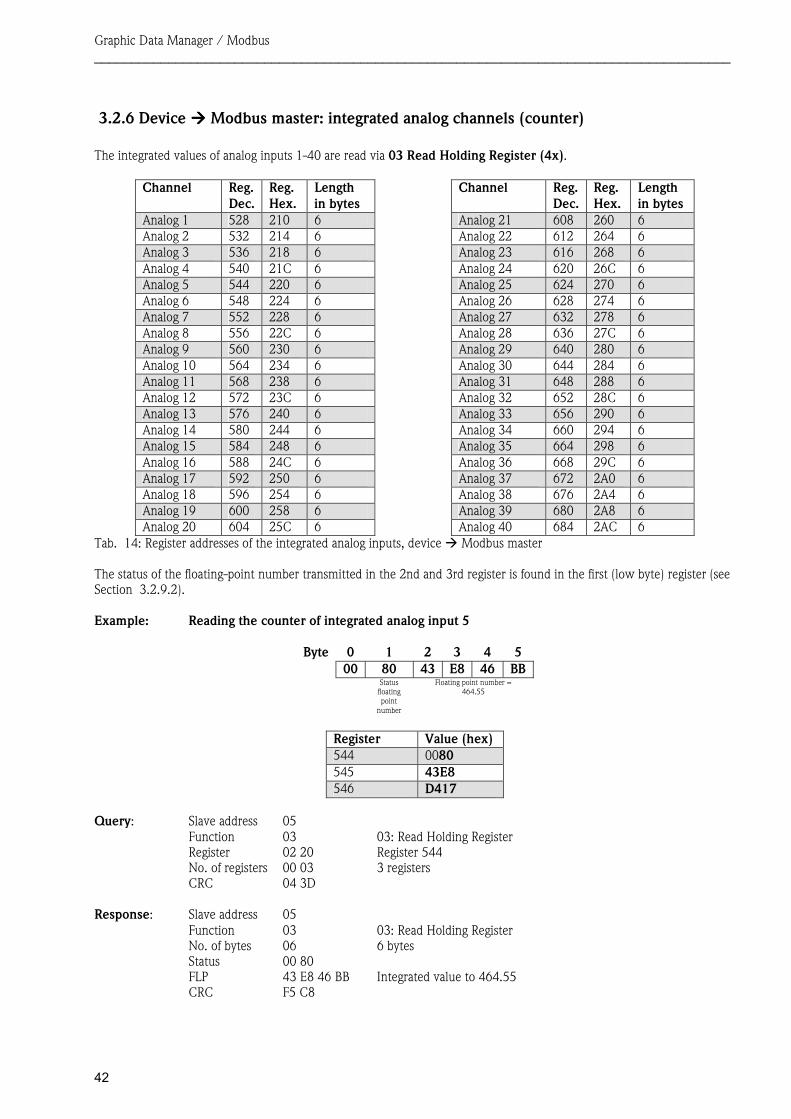
3.2.6 Device ���� Modbus master: integrated analog channels (counter) The integrated values of analog inputs 1-40 are read via 03 Read Holding Register (4x).
Channel Reg. Dec.
Reg. Hex.
Length in bytes
Channel Reg. Dec.
Reg. Hex.
Length in bytes
Analog 1 528 210 6 Analog 21 608 260 6Analog 2 532 214 6 Analog 22 612 264 6 Analog 3 536 218 6 Analog 23 616 268 6Analog 4 540 21C 6 Analog 24 620 26C 6 Analog 5 544 220 6 Analog 25 624 270 6Analog 6 548 224 6 Analog 26 628 274 6 Analog 7 552 228 6 Analog 27 632 278 6Analog 8 556 22C 6 Analog 28 636 27C 6 Analog 9 560 230 6 Analog 29 640 280 6Analog 10 564 234 6 Analog 30 644 284 6 Analog 11 568 238 6 Analog 31 648 288 6Analog 12 572 23C 6 Analog 32 652 28C 6 Analog 13 576 240 6 Analog 33 656 290 6Analog 14 580 244 6 Analog 34 660 294 6 Analog 15 584 248 6 Analog 35 664 298 6Analog 16 588 24C 6 Analog 36 668 29C 6 Analog 17 592 250 6 Analog 37 672 2A0 6Analog 18 596 254 6 Analog 38 676 2A4 6 Analog 19 600 258 6 Analog 39 680 2A8 6Analog 20 604 25C 6 Analog 40 684 2AC 6
The status of the floating-point number transmitted in the 2nd and 3rd register is found in the first (low byte) register (see Section 3.2.9.2). Example: Reading the counter of integrated analog input 5
Byte 0 1 2 3 4 500 80 43 E8 46 BB
Status floating point
number
Floating point number = 464.55
Register Value (hex) 544 0080 545 43E8 546 D417
Query: Slave address 05 Function 03 03: Read Holding Register Register 02 20 Register 544 No. of registers 00 03 3 registers CRC 04 3D
Response: Slave address 05 Function 03 03: Read Holding Register No. of bytes 06 6 bytes Status 00 80 FLP 43 E8 46 BB Integrated value to 464.55 CRC F5 C8
Tab. 14: Register addresses of the integrated analog inputs, device � Modbus master
Graphic Data Manager / Modbus ______________________________________________________________________________________
43
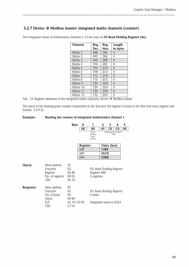
3.2.7 Device ���� Modbus master: integrated maths channels (counter) The integrated values of mathematics channels 1-12 are read via 03 Read Holding Register (4x).
Channel Reg. Dec.
Reg. Hex.
Length in bytes
Maths 1 688 2B0 6Maths 2 692 2B4 6 Maths 3 696 2B8 6Maths 4 700 2BC 6 Maths 5 704 2C0 6Maths 6 708 2C4 6 Maths 7 712 2C8 6Maths 8 716 2CC 6 Mathe 9 720 2D0 6Mathe 10 724 2D4 6 Mathe 11 728 2D8 6Mathe 12 732 2DC 6
The status of the floating-point number transmitted in the 2nd and 3rd register is found in the first (low byte) register (see Section 3.2.9.2). Example: Reading the counter of integrated mathematics channel 1
Byte 0 1 2 3 4 500 80 45 1D C0 00
Status floating point
number
Floating point number = 2524
Register Value (hex) 688 0080 689 451D 690 C000
Query: Slave address 05 Function 03 03: Read Holding Register Register 02 B0 Register 688 No. of registers 00 03 3 registers CRC 04 10
Response: Slave address 05 Function 03 03: Read Holding Register No. of bytes 06 6 bytes Status 00 80 FLP 45 1D C0 00 Integrated value to 2524 CRC C7 61
Tab. 15: Register addresses of the integrated maths channels, device � Modbus master
Graphic Data Manager / Modbus ______________________________________________________________________________________
44
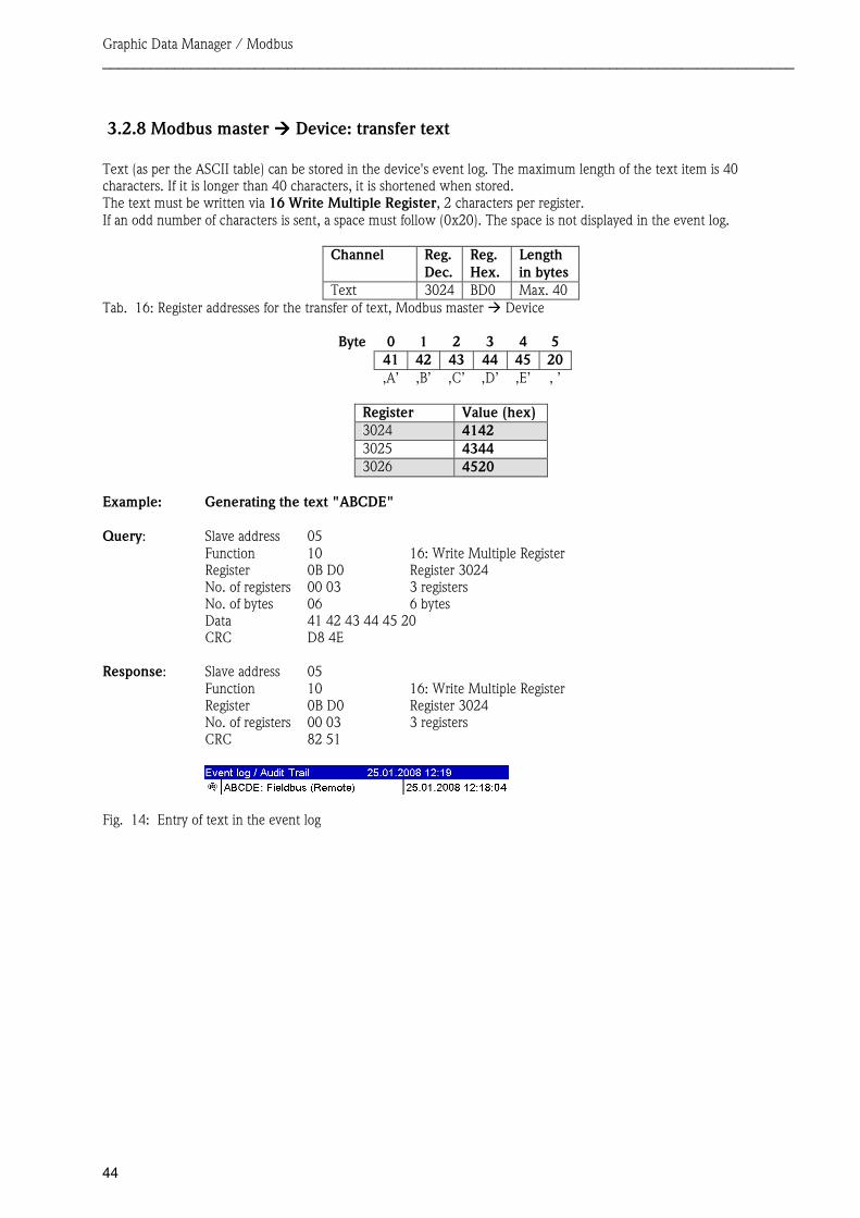
3.2.8 Modbus master ���� Device: transfer text Text (as per the ASCII table) can be stored in the device's event log. The maximum length of the text item is 40 characters. If it is longer than 40 characters, it is shortened when stored. The text must be written via 16 Write Multiple Register, 2 characters per register. If an odd number of characters is sent, a space must follow (0x20). The space is not displayed in the event log.
Channel Reg. Dec.
Reg. Hex.
Length in bytes
Text 3024 BD0 Max. 40
Byte 0 1 2 3 4 5 41 42 43 44 45 20
‚A’ ‚B’ ‚C’ ‚D’ ‚E’ ‚ ’
Register Value (hex) 3024 4142 3025 4344 3026 4520
Example: Generating the text "ABCDE" Query: Slave address 05
Function 10 16: Write Multiple Register Register 0B D0 Register 3024 No. of registers 00 03 3 registers No. of bytes 06 6 bytes Data 41 42 43 44 45 20 CRC D8 4E
Response: Slave address 05 Function 10 16: Write Multiple Register Register 0B D0 Register 3024 No. of registers 00 03 3 registers CRC 82 51
Tab. 16: Register addresses for the transfer of text, Modbus master � Device
Fig. 14: Entry of text in the event log
Graphic Data Manager / Modbus ______________________________________________________________________________________
45
3.2.9 Structure of the process values
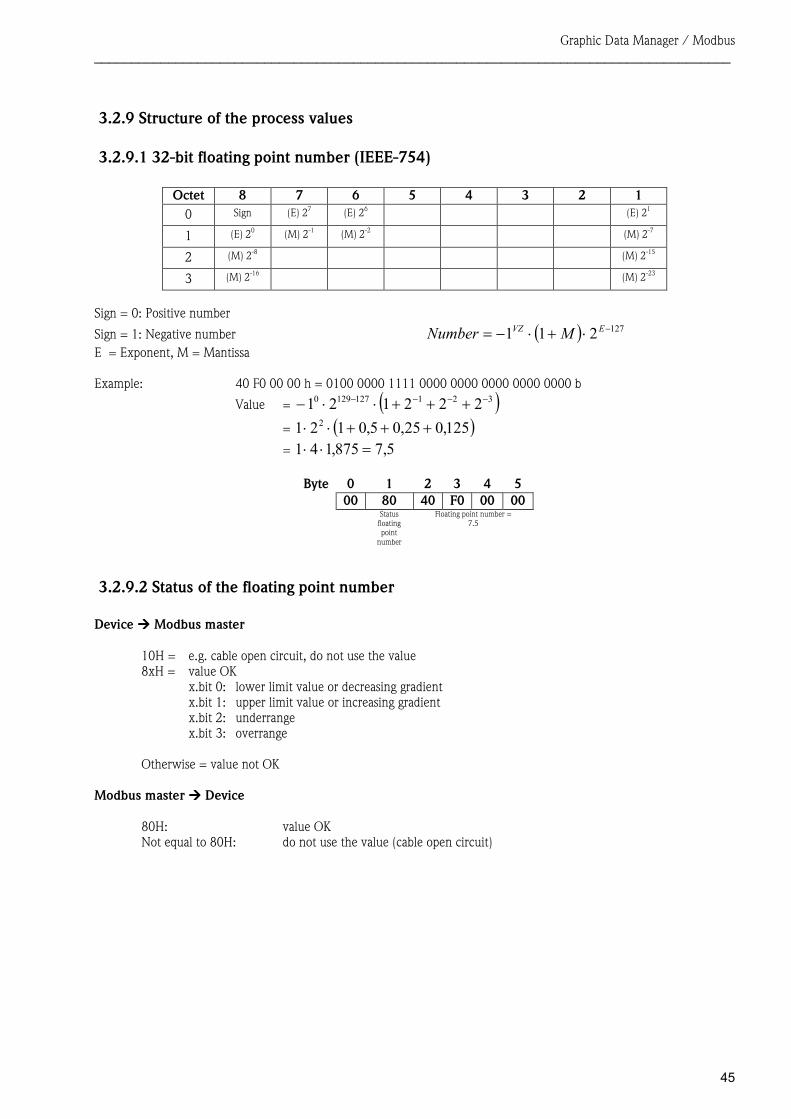
3.2.9.1 32-bit floating point number (IEEE-754)
Octet 8 7 6 5 4 3 2 1 0 Sign (E) 27 (E) 26 (E) 21
1 (E) 20 (M) 2-1 (M) 2-2 (M) 2-7
2 (M) 2-8 (M) 2-15
3 (M) 2-16 (M) 2-23
Sign = 0: Positive number
Sign = 1: Negative number ( ) 127211 −⋅+⋅−= EVZ MNumber E = Exponent, M = Mantissa Example: 40 F0 00 00 h = 0100 0000 1111 0000 0000 0000 0000 0000 b
Value = ( )3211271290 222121 −−−− +++⋅⋅−= ( )125,025,05,0121 2 +++⋅⋅= 5,7875,141 =⋅⋅
Byte 0 1 2 3 4 500 80 40 F0 00 00
Status floating point
number
Floating point number = 7.5
3.2.9.2 Status of the floating point number Device ���� Modbus master
10H = e.g. cable open circuit, do not use the value 8xH = value OK
x.bit 0: lower limit value or decreasing gradient x.bit 1: upper limit value or increasing gradient x.bit 2: underrange x.bit 3: overrange
Otherwise = value not OK
Modbus master ���� Device
80H: value OK Not equal to 80H: do not use the value (cable open circuit)
Graphic Data Manager / Modbus ______________________________________________________________________________________
46
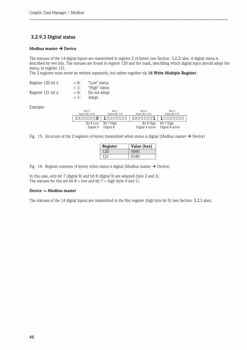
3.2.9.3 Digital status Modbus master ���� Device The statuses of the 14 digital inputs are transmitted in register 2 (4 bytes) (see Section 3.2.2) also. A digital status is described by two bits. The statuses are found in register 120 and the mask, describing which digital input should adopt the status, in register 121. The 2 registers must never be written separately, but rather together via 16 Write Multiple Register.
Register 120 bit x = 0: "Low" status = 1: "High" status Register 121 bit x = 0: Do not adopt = 1: Adopt Example:
Byte 0 Status (Bit 15-8)
Byte 1 Status (Bit 7-0)
Byte 2 Mask (Bit 15-8)
Byte 3 Mask (Bit 7-0)
XX000000 10000000 XX000001 10000000Bit 8 LowDigital 9
Bit 7 High Digital 8
Bit 8 HighDigital 9 active
Bit 7 High Digital 8 active
Register Value (hex) 120 0080 121 0180
In this case, only bit 7 (digital 8) and bit 8 (digital 9) are adopted (byte 2 and 3). The statuses for this are bit 8 = low and bit 7 = high (byte 0 and 1). Device -> Modbus master The statuses of the 14 digital inputs are transmitted in the first register (high byte bit 0) (see Section 3.2.5 also).
Fig. 15: Structure of the 2 registers (4 bytes) transmitted when status is digital (Modbus master � Device)
Fig. 16: Register contents (4 bytes) when status is digital (Modbus master � Device)
Graphic Data Manager / Modbus ______________________________________________________________________________________
47
4 List of abbreviations/explanation of terms Modbus module: The Modbus RTU or Modbus ETH slave plug-in module that is plugged into the rear of the
device Modbus master: All equipment, such as the PLC and PC plug-in boards, that have a Modbus master function
5 Index
A
Analog channel ...........................................................32
B
Baud rate ....................................................................29
C
Connections..........................................................27, 28
D
Data transmission........................................................35 Digital status ...............................................................46
F
Floating point number.................................................45 Floating point number status.......................................45
Function ......................................................................29
I
Inputs ..........................................................................32
L
LED, operation mode ...........................................27, 28 LED, status ...........................................................27, 29
M
Mathematics channel ..................................................32
O
Outputs .......................................................................32

BA260R/09/de/07.08 No. 71068853 MS-Word