modbus slave e
DESCRIPTION
Modbus slave E MitsubishiTRANSCRIPT

Modbus SlaveCommunication

Record of Revisions
Reference numbers are shown at the bottom left corner on the back cover of each manual.
Printing Date Reference No. Revised Contents
July, 2006 1046NE0 First edition


Preface
Thank you for selecting the MONITOUCH V7/V6 series.For correct set-up of the V7/V6 series, you are requested to read through this manual to understand more about the product.For more information about the V7/V6 series, refer to the following related manuals.
For further details about PLCs (programmable logic controllers), see the manual attached to each PLC.
Manual Name Contents Reference No.
Reference Manual (Operation) The V-SFT operating procedure is described. 1043NE
Reference Manual (Function) The functions and instructions of the V7/V6 series are explained.
1044NE
PLC Connection Manual Connections with various PLCs and universal serial communications are explained.
2200NE
V7 Hardware Specifications Notes on usage and hardware specifications for the V7 series are described.
2010NE
V706 Hardware Specifications Notes on usage and hardware specifications for the V706 are described.
2012NE
V6 Hardware Specifications Notes on usage and hardware specifications for the V6 series are described.
2006NE
Temperature Control Network The temperature control network function is explained.
1033NE
Connection with AB Control Logix The connection, communication parameters and tag setting for AB Control Logix are explained.
1041NE
M-CARD SFT Operation Manual The operating procedure of the memory card editor is described.
1023NE
V-SFT Additional Specifications Additional specifications for the Reference Manual are explained.
5044NE
Notes:
1. This manual may not, in whole or in part, be printed or reproduced without the prior written consent of Hakko Electronics Co., Ltd.
2. The information in this manual is subject to change without prior notice.
3. Windows and Excel are registered trademarks of Microsoft Corporation in the United States and other countries.
4. All other company names or product names are trademarks or registered trademarks of their respective holders.
5. This manual is intended to give accurate information about MONITOUCH hardware. If you have any questions, please contact your local distributor.


Notes on Safe Usage of MONITOUCH
In this manual, you will find various notes categorized under the following levels with the signal words “DANGER,” and “CAUTION.”
Note that there is a possibility that the item listed with may have serious ramifications.
DANGER Indicates an imminently hazardous situation which, if not avoided, will result in death or serious injury.
CAUTION Indicates a potentially hazardous situation which, if not avoided, may result in minor or moderate injury and could cause property damage.
• Never use the input function of MONITOUCH for operations that may threaten human life or damage the system, such as switches used in case of emergency. Please design the system so that it can cope with malfunction of a touch switch. A malfunction of the touch switch will result in machine accident or damage.
• Turn off the power supply when you set up the unit, connect new cables or perform maintenance or inspections. Otherwise, electrical shock or damage may occur.
• Never touch any terminals while the power is on. Otherwise, electric shock may occur.• You must put a cover on the terminals on the unit when you turn the power on and operate the unit. Without
the terminal cover in place, electric shock may occur.• The liquid crystal in the LCD panel is a hazardous substance. If the LCD panel is damaged, do not ingest
the leaked liquid crystal. If the liquid crystal spills on your skin or clothing, use soap and wash off thoroughly.• For MONITOUCH using a lithium battery, never disassemble, recharge, deform by pressure, short-circuit,
nor reverse the polarity of the battery, or dispose of the battery in fire. Failure to follow these conditions will lead to explosion or fire.
• For MONITOUCH using a lithium battery, never use a battery that is deformed, leaks, or shows any other signs of abnormality. Failure to follow these conditions will lead to explosion or fire.
CAUTION
DANGER

• Check the appearance of the unit when it is unpacked. Do not use the unit if any damage or deformation is found. Failure to do so may lead to fire, damage or malfunction.
• For use in a facility or for a system related to nuclear energy, aerospace, medical, traffic equipment, or mobile installations, please consult your local distributor.
• Operate (or store) MONITOUCH under the conditions indicated in this manual and related manuals. Failure to do so could cause fire, malfunction, physical damage or deterioration.
• Understand the following environmental limits for use and storage of MONITOUCH. Otherwise, fire or damage to the unit may result.
- Avoid locations where there is a possibility that water, corrosive gas, flammable gas, solvents, grinding fluids or cutting oil can come into contact with the unit.
- Avoid high temperature, high humidity, and outside weather conditions, such as wind, rain or direct sunlight.
- Avoid locations where excessive dust, salt, and metallic particles are present.- Avoid installing the unit in a location where vibration or physical shock may be transmitted.
• Equipment must be correctly mounted so that the main terminal of MONITOUCH cannot be touched inadvertently. Otherwise, an accident or electric shock may occur.
• Tighten the fixtures of MONITOUCH with a torque in the specified range. Excessive tightening may distort the panel surface. Loose tightening may cause MONITOUCH to come off, malfunction or be short-circuited.
• Check periodically that terminal screws on the power supply terminal block and fixtures are firmly tightened. Loosened screws may result in fire or malfunction.
• Tighten terminal screws on the power supply terminal block equally to a torque of 0.5 N•m. Improper tightening of screws may result in fire, malfunction, or other trouble.
• MONITOUCH has a glass screen. Do not drop or give physical shock to the unit. Otherwise, the screen may be damaged.
• Connect the cables correctly to the terminals of MONITOUCH in accordance with the specified voltage and wattage. Over-voltage, over-wattage or incorrect cable connection could cause fire, malfunction or damage to the unit.
• Be sure to establish a ground of MONITOUCH. The FG terminal must be used exclusively for the unit with the level of grounding resistance less than 100Ω. Otherwise, electric shock or fire may occur.
• Prevent any conductive particles from entering into MONITOUCH. Failure to do so may lead to fire, damage or malfunction.
• After wiring is finished, remove the paper used as a dust cover before starting to operate MONITOUCH. Operation with the cover attached may result in accident, fire, malfunction, or other trouble.
• Do not attempt to repair MONITOUCH at your site. Ask Hakko or the designated contractor for repair.• Do not disassemble or modify MONITOUCH. Otherwise, it may cause a malfunction.• Hakko Electronics Co., Ltd. is not responsible for any damages resulting from repair, overhaul or
modification of MONITOUCH that was performed by an unauthorized person.• Do not use a sharp-pointed tool when pressing a touch switch. Doing so may damage the screen.• Only experts are authorized to set up the unit, connect the cables or perform maintenance and inspections.• For MONITOUCH using a lithium battery, handle the battery with care. The combustible materials such as
lithium or organic solvent contained in the battery may generate heat, explode, or catch fire, resulting in personal injury or fire. Read related manuals carefully and handle the lithium battery correctly as instructed.
• When using a MONITOUCH that has an analog switch resolution with resistance film, do not press two or more points on the screen at the same time. If two or more positions are pressed at the same time, the switch located between the pressed positions will activate.
• Take safety precautions during such operations as setting change during running, forced output, start, and stop. Any misoperation may cause unexpected machine motions, resulting in machine accident or damage.
• In facilities where a failure of MONITOUCH could lead to accident threatening human life or other serious damage, be sure that the facilities are equipped with adequate safeguards.
• At the time of disposal, MONITOUCH must be treated as industrial waste.• Before touching MONITOUCH, discharge static electricity from your body by touching grounded metal.
Excessive static electricity may cause malfunction or other trouble.
CAUTION

[General Notes]• Never bundle control cables and input/output cables with high-voltage and large-current carrying cables such
as power supply cables. Keep these cables at least 200 mm away from high-voltage and large-current carrying cables. Otherwise, malfunction may occur due to noise.
• Plug connectors or sockets of MONITOUCH in their correct orientation. Otherwise, malfunctions may occur.• Do not use thinners for cleaning because they may discolor the MONITOUCH surface. Use an alcohol-based
cleaner which is commercially available.• If a data receive error occurs when MONITOUCH and the counterpart (PLC, temperature controller, etc.) are
started at the same time, read the manual for the counterpart unit and handle the error correctly.• Avoid discharging static electricity on the mounting panel of MONITOUCH. Static charges can damage the
unit and cause malfunctions. Otherwise, malfunction may occur due to noise.• Avoid prolonged display of any fixed pattern. Due to the characteristics of the liquid crystal display, an
afterimage may occur. If a prolonged display of a fixed pattern is expected, use the auto OFF function of the backlight.

Contents
Preface
Notes on Safe Usage of MONITOUCH
1. OutlineModbus Protocol.................................................................................................................................. 1-1Modbus Slave Communication............................................................................................................ 1-2
2. ConnectionApplicable Devices .............................................................................................................................. 2-1Communication Setting (For Slave)..................................................................................................... 2-1Connection .......................................................................................................................................... 2-2
3. Modbus Slave CommunicationOutline of Communication ................................................................................................................... 3-1Slave Setting ....................................................................................................................................... 3-2Master Setting ..................................................................................................................................... 3-6
4. Use of MONITOUCH as Modbus MasterOutline of Communication ................................................................................................................... 4-1Slave Setting ....................................................................................................................................... 4-1Master Setting ..................................................................................................................................... 4-1Connection .......................................................................................................................................... 4-2Connection with Multiple MONITOUCH as Slaves.............................................................................. 4-3
5. AppendixSystem Memory ($s) ........................................................................................................................... 5-1Error..................................................................................................................................................... 5-1

1
1. Outline 1-1
1. Outline
Modbus Protocol
• The Modbus protocol, developed by Modicon, is a communication protocol widely adopted for PLCs or other devices.
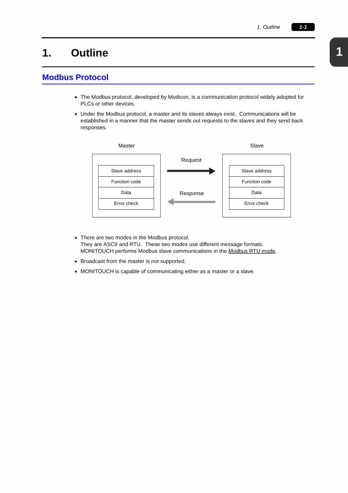
• Under the Modbus protocol, a master and its slaves always exist. Communications will be established in a manner that the master sends out requests to the slaves and they send back responses.
• There are two modes in the Modbus protocol.They are ASCII and RTU. These two modes use different message formats.MONITOUCH performs Modbus slave communications in the Modbus RTU mode.
• Broadcast from the master is not supported.
• MONITOUCH is capable of communicating either as a master or a slave.
Master Slave
Slave address
Function code
Data
Error check
Slave address
Function code
Data
Error check
Request
Response
1-2 1. Outline
Modbus Slave Communication
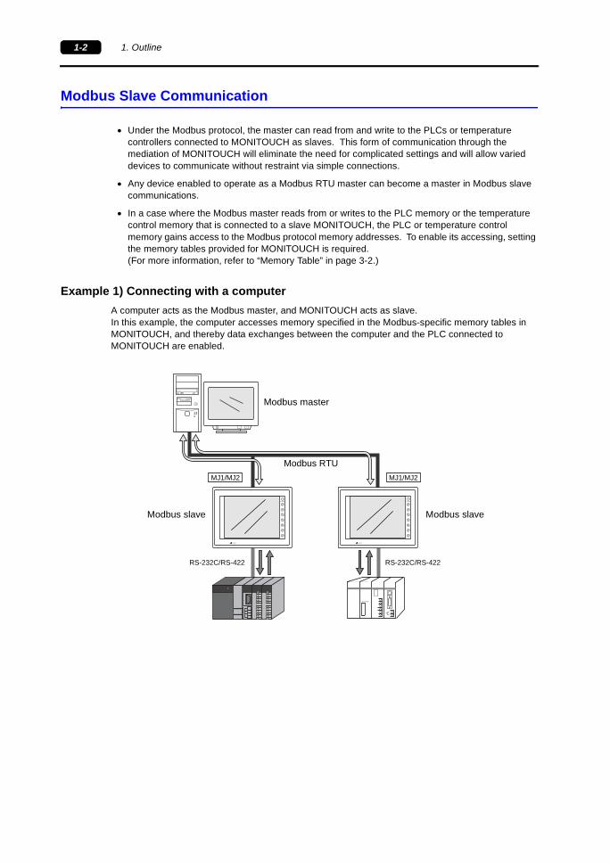
• Under the Modbus protocol, the master can read from and write to the PLCs or temperature controllers connected to MONITOUCH as slaves. This form of communication through the mediation of MONITOUCH will eliminate the need for complicated settings and will allow varied devices to communicate without restraint via simple connections.
• Any device enabled to operate as a Modbus RTU master can become a master in Modbus slave communications.
• In a case where the Modbus master reads from or writes to the PLC memory or the temperature control memory that is connected to a slave MONITOUCH, the PLC or temperature control memory gains access to the Modbus protocol memory addresses. To enable its accessing, setting the memory tables provided for MONITOUCH is required.(For more information, refer to “Memory Table” in page 3-2.)
Example 1) Connecting with a computerA computer acts as the Modbus master, and MONITOUCH acts as slave.In this example, the computer accesses memory specified in the Modbus-specific memory tables in MONITOUCH, and thereby data exchanges between the computer and the PLC connected to MONITOUCH are enabled.
RESET
disc
RS-232C/RS-422
Modbus RTU
F1
F2
F3
F4
F5
F6
F7
SYSTEM
POWER
F1
F2
F3
F4
F5
F6
F7
SYSTEM
POWER
MJ1/MJ2 MJ1/MJ2
PROGRAMMER
RS-232C/RS-422
Modbus master
Modbus slave Modbus slave

1
1. Outline 1-3
Example 2) Connecting between MONITOUCH
MONITOUCH acts as both the Modbus master and the Modbus slave.The master gains access to the slave on the temperature control network (Modbus Free).The master accesses the Modbus addresses of the slave, and thereby can receive data from the slave-side PLC. At the same time, the master-side PLC can send data to the slave-side.
Connection OutlineThe Modbus master can be connected to the modular jack (MJ1/MJ2) of MONITOUCH as a Modbus slave via RS-232C or RS-485.
RS-232C/RS-422
Modbus RTU
F1
F2
F3
F4
F5
F6
F7
SYSTEM
POWER
F1
F2
F3
F4
F5
F6
F7
SYSTEM
POWER
MJ1/MJ2 MJ1/MJ2
PROGRAMMER
RS-232C/RS-422
Modbus master Modbus slave
RESET
disc
RS-232C
F1
F2
F3
F4
F5
F6
F7
SYSTEM
POWER
MJ1/MJ2
RS-232C/RS-422
CN1
RESET
disc
RS-232C/RS-422
RS-485
F1
F2
F3
F4
F5
F6
F7
SYSTEM
POWER
F1
F2
F3
F4
F5
F6
F7
SYSTEM
POWER
MJ1/MJ2 MJ1/MJ2
PROGRAMMER
RS-232C/RS-422
CN1 CN1
Via RS-232C Via RS-485
A maximum of 31 sets of MONITOUCH are connectable.
1-4 1. Outline
Please use this page freely.

2
2. Connection 2-1
2. Connection
Applicable Devices
• Slave sideV7/V6/V706 series
* When one single V706 series is used, the MJ2 is dedicated to PLC connection.Typical users use the MJ1 for Modbus slave communication; however, with an option unit DU-01 installed, the MJ1 can also be used for Modbus slave communication.
• Master sideDevices which support to the Modbus RTU mode
* The V7/V6/V706 series is usable also as the Modbus master.(For more information, refer to “Chapter 4 Use of MONITOUCH as Modbus Master”.)
Communication Setting (For Slave)
Setting Procedure[System Setting] → [Modbus Slave Communication Setting] → [Communication Setting] → [Modbus slave communication setting] dialog
1. In the dialog, select [Modbus RTU] for [Comm. Protocol] (default setting: Not used).
2. The [Refer to modular] button becomes enabled. Click the button.The [Modbus Slave Table] dialog is displayed. Choose the MJ port to be used for Modbus slave communication and check [Modbus Slave].
Note: [Modbus Slave] and [V-Link] cannot be used simultaneously.
Setting ItemsThe following setting items are provided for the MONITOUCH to act as a Modbus slave.
*1 A baud rate of 115,200 bps is not available for V606, V606i, V606e, and V609E.
*2 Timeout:The item [Timeout] for Modbus slave communication refers to the time for monitoring commands to be received from the master.When the specified timeout period has elapsed and no more data arrives, the data that has been received so far is recognized as one command.
Setting Items Setting (underlined as a default)Comm. Protocol Modbus RTU (fixed)Data Length 8-bit (fixed)Signal Level RS-232C, RS-485Stop Bit 1-bit, 2-bit
Baud Rate 4800, 9600, 19200, 38400, 57600, 115200 bps *1
Local No. 1 to 31 (“0” not usable)Send Delay (× msec) 0 to 255Parity None, Odd, Even
Timeout (× msec) 0 to 25 (2) *2
2-2 2. Connection
Connection
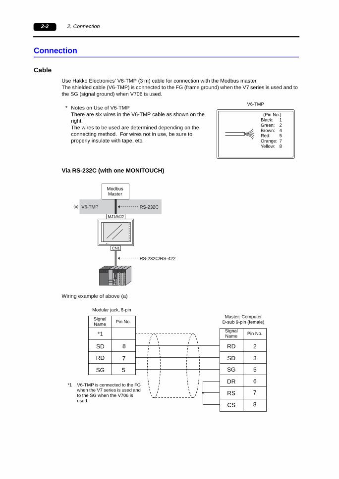
CableUse Hakko Electronics’ V6-TMP (3 m) cable for connection with the Modbus master.The shielded cable (V6-TMP) is connected to the FG (frame ground) when the V7 series is used and to the SG (signal ground) when V706 is used.
* Notes on Use of V6-TMPThere are six wires in the V6-TMP cable as shown on the right.The wires to be used are determined depending on the connecting method. For wires not in use, be sure to properly insulate with tape, etc.
Via RS-232C (with one MONITOUCH)
Wiring example of above (a)
V6-TMP
(Pin No.)Black: 1Green: 2Brown: 4Red: 5Orange: 7Yellow: 8
(a) V6-TMP RS-232C
F1
F2
F3
F4
F5
F6
F7
SYSTEM
POWER
MJ1/MJ2
RS-232C/RS-422
CN1
ModbusMaster
SD 8 RD
SD
SG
CS
2
3
5
6
RD
SG
7
5
RS 7
8
DR
*1
Master: ComputerD-sub 9-pin (female)Pin No.
Modular jack, 8-pin
Signal Name
Pin No.Signal Name
*1 V6-TMP is connected to the FG when the V7 series is used and to the SG when the V706 is used.

2
2. Connection 2-3
Via RS-485 (with a maximum of 31 MONITOUCHs)
Wiring example of above (a) and (b)
(a)
(b) V6-TMP
MJ2/1 MJ2/1 MJ2/1
CN1 CN1 CN1
RS-232CRS-422
PLC PLC PLC
RS-485
* * *F1
F2
F3
F4
F5
F6
F7
SYSTEM
POWER
F1
F2
F3
F4
F5
F6
F7
SYSTEM
POWER
F1
F2
F3
F4
F5
F6
F7
SYSTEM
POWER
PROGRAMMER
ModbusMaster RS-232C → RS485
conversion
Terminal block
* 0.5-m-long cable recommended (1.0 m maximum)
Terminal block
Terminal block
+ 1
+
−
RS-485
− 2
+ 1
− 2
+
−
+
−
(a)
(b)
SG 5 SG 5
SG SG SG
FG FG FG
*1 *1
Signal Name
V7 seriesModular jack, 8-pin
Pin No.
V7 seriesModular jack, 8-pin
Signal Name
Signal Name
Signal Name
Terminal Terminal
Signal Name Pin No.
*1 V6-TMP is connected to the FG when the V7 series is used and to the SG when the V706 is used.
2-4 2. Connection
Please use this page freely.
3
3. Modbus Slave Communication 3-1
3. Modbus Slave Communication
Outline of Communication
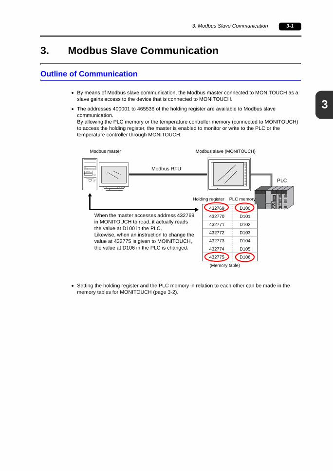
• By means of Modbus slave communication, the Modbus master connected to MONITOUCH as a slave gains access to the device that is connected to MONITOUCH.
• The addresses 400001 to 465536 of the holding register are available to Modbus slave communication.By allowing the PLC memory or the temperature controller memory (connected to MONITOUCH) to access the holding register, the master is enabled to monitor or write to the PLC or the temperature controller through MONITOUCH.
• Setting the holding register and the PLC memory in relation to each other can be made in the memory tables for MONITOUCH (page 3-2).
RESET
discF1
F2
F3
F4
F5
F6
F7
SYSTEM
POWER
Modbus RTU
D100
D101
D102
D103
D104
D105
D106
432769
432770
432771
432772
432773
432774
432775
PLC
Modbus master Modbus slave (MONITOUCH)
Holding register PLC memory
(Memory table)
When the master accesses address 432769 in MONITOUCH to read, it actually reads the value at D100 in the PLC.Likewise, when an instruction to change the value at 432775 is given to MOINITOUCH, the value at D106 in the PLC is changed.
3-2 3. Modbus Slave Communication
Slave Setting
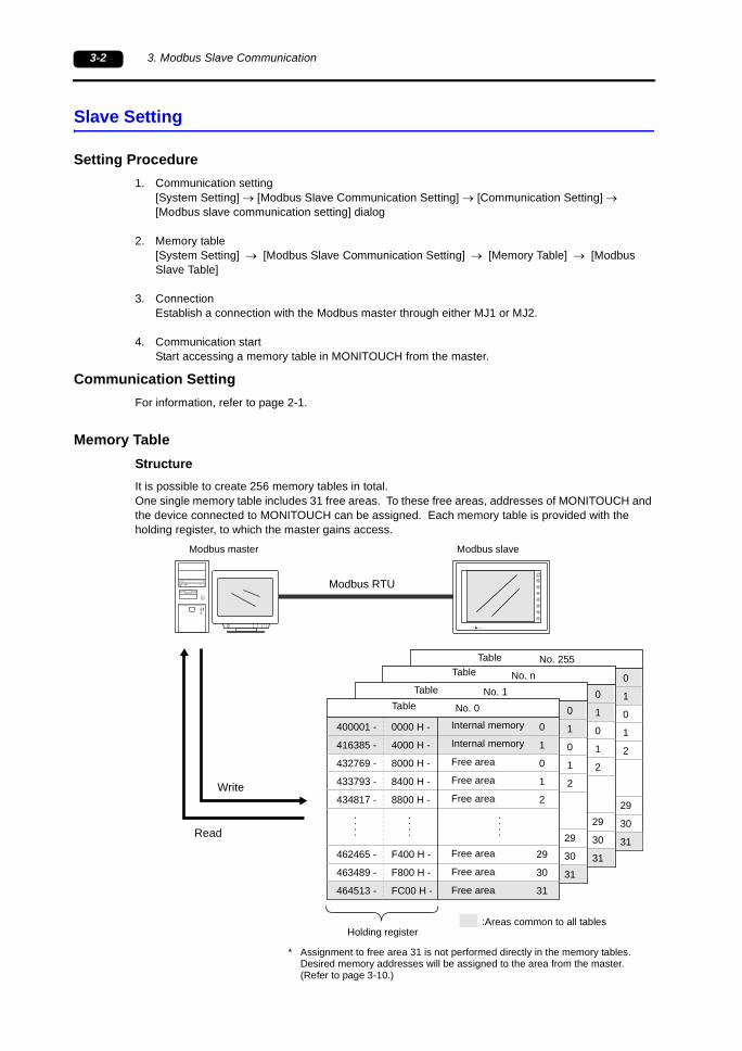
Setting Procedure1. Communication setting
[System Setting] → [Modbus Slave Communication Setting] → [Communication Setting] → [Modbus slave communication setting] dialog
2. Memory table[System Setting] → [Modbus Slave Communication Setting] → [Memory Table] → [Modbus Slave Table]
3. ConnectionEstablish a connection with the Modbus master through either MJ1 or MJ2.
4. Communication startStart accessing a memory table in MONITOUCH from the master.
Communication SettingFor information, refer to page 2-1.
Memory TableStructureIt is possible to create 256 memory tables in total.One single memory table includes 31 free areas. To these free areas, addresses of MONITOUCH and the device connected to MONITOUCH can be assigned. Each memory table is provided with the holding register, to which the master gains access.
RESET
discF1
F2
F3
F4
F5
F6
F7
SYSTEM
POWER
Modbus RTU
0
1
0
1
2
29
30
31
0000 H -
4000 H -
8000 H -
8400 H -
8800 H -
F400 H -
F800 H -
FC00 H -
No. 255
400001 -
416385 -
432769 -
433793 -
434817 -
462465 -
463489 -
464513 -
0
1
0
1
2
29
30
31
0000 H -
4000 H -
8000 H -
8400 H -
8800 H -
F400 H -
F800 H -
FC00 H -
No. n
400001 -
416385 -
432769 -
433793 -
434817 -
462465 -
463489 -
464513 -
0
1
0
1
2
29
30
31
0000 H -
4000 H -
8000 H -
8400 H -
8800 H -
F400 H -
F800 H -
FC00 H -
No. 1
400001 -
416385 -
432769 -
433793 -
434817 -
462465 -
463489 -
464513 -
0
1
0
1
2
29
30
31
0000 H -
4000 H -
8000 H -
8400 H -
8800 H -
F400 H -
F800 H -
FC00 H -
No. 0
400001 -
416385 -
432769 -
433793 -
434817 -
462465 -
463489 -
464513 -
TableTable
TableTable
Internal memory
Internal memory
Free area
Free area
Free area
Free area
Free area
Free area
Holding register
Read
Write
Modbus master Modbus slave
* Assignment to free area 31 is not performed directly in the memory tables.Desired memory addresses will be assigned to the area from the master. (Refer to page 3-10.)
:Areas common to all tables
3
3. Modbus Slave Communication 3-3
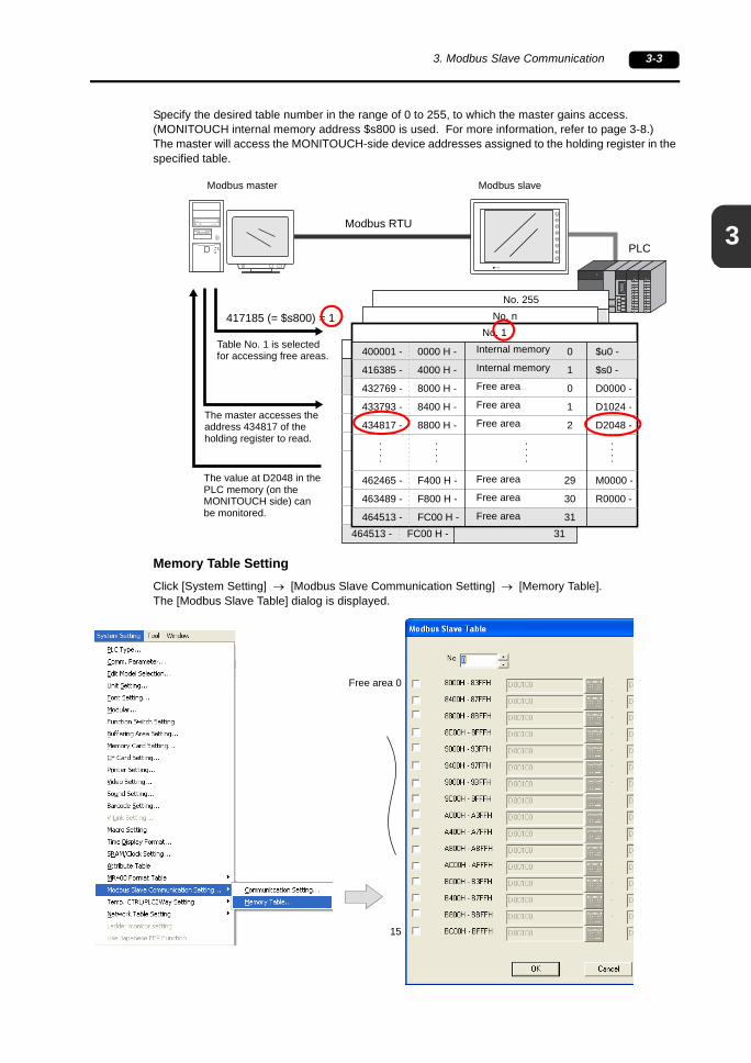
Specify the desired table number in the range of 0 to 255, to which the master gains access. (MONITOUCH internal memory address $s800 is used. For more information, refer to page 3-8.)The master will access the MONITOUCH-side device addresses assigned to the holding register in the specified table.
Memory Table SettingClick [System Setting] → [Modbus Slave Communication Setting] → [Memory Table].The [Modbus Slave Table] dialog is displayed.
PLCRESET
discF1
F2
F3
F4
F5
F6
F7
SYSTEM
POWER
Modbus RTU
0
1
0
1
2
29
30
31
0000 H -
4000 H -
8000 H -
8400 H -
8800 H -
F400 H -
F800 H -
FC00 H -
No. 255
400001 -
416385 -
432769 -
433793 -
434817 -
462465 -
463489 -
464513 -
0
1
0
1
2
29
30
31
0000 H -
4000 H -
8000 H -
8400 H -
8800 H -
F400 H -
F800 H -
FC00 H -
No. n
400001 -
416385 -
432769 -
433793 -
434817 -
462465 -
463489 -
464513 -
0
1
0
1
2
29
30
31
0000 H -
4000 H -
8000 H -
8400 H -
8800 H -
F400 H -
F800 H -
FC00 H -
No. 0
400001 -
416385 -
432769 -
433793 -
434817 -
462465 -
463489 -
464513 -
417185 (= $s800) = 1
0
1
0
1
2
29
30
31
0000 H -
4000 H -
8000 H -
8400 H -
8800 H -
F400 H -
F800 H -
FC00 H -
No. 1
400001 -
416385 -
432769 -
433793 -
434817 -
462465 -
463489 -
464513 -
$u0 -
$s0 -
D0000 -
D1024 -
D2048 -
M0000 -
R0000 -
Table No. 1 is selected for accessing free areas.
Modbus master Modbus slave
The master accesses the address 434817 of the holding register to read.
The value at D2048 in the PLC memory (on the MONITOUCH side) can be monitored.
Internal memory
Internal memory
Free area
Free area
Free area
Free area
Free area
Free area
Free area 0
15
3-4 3. Modbus Slave Communication
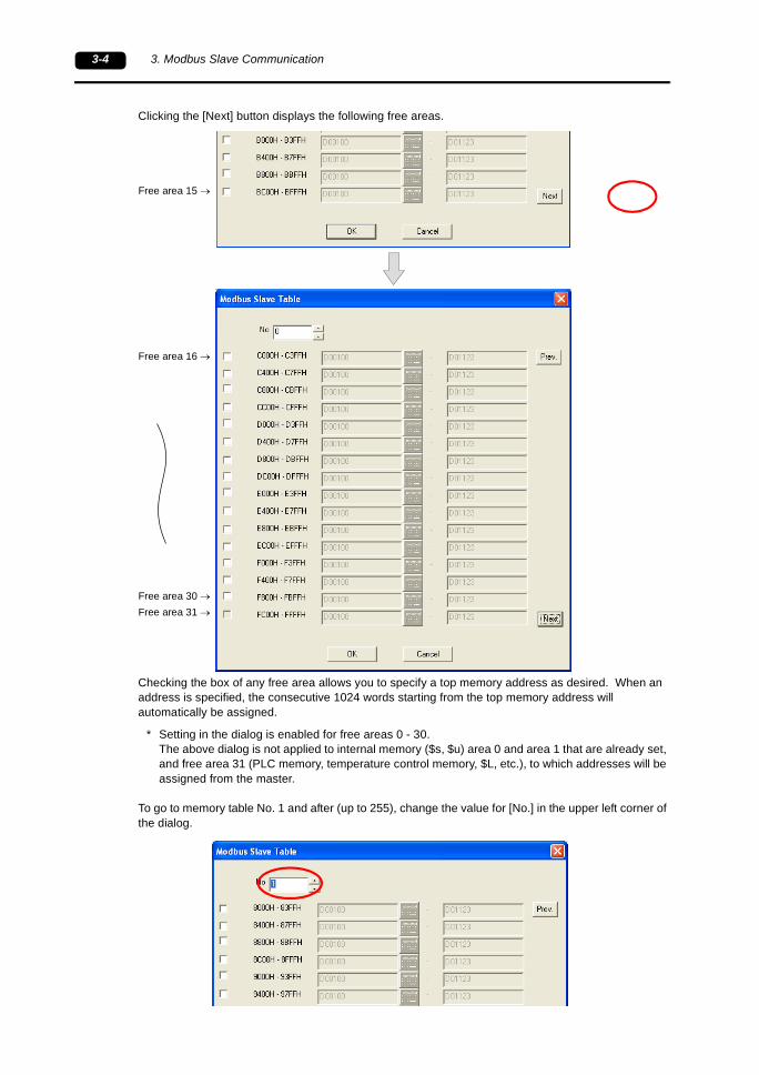
Clicking the [Next] button displays the following free areas.
Checking the box of any free area allows you to specify a top memory address as desired. When an address is specified, the consecutive 1024 words starting from the top memory address will automatically be assigned.
* Setting in the dialog is enabled for free areas 0 - 30.The above dialog is not applied to internal memory ($s, $u) area 0 and area 1 that are already set, and free area 31 (PLC memory, temperature control memory, $L, etc.), to which addresses will be assigned from the master.
To go to memory table No. 1 and after (up to 255), change the value for [No.] in the upper left corner of the dialog.
Free area 16 →
Free area 15 →
Free area 30 →Free area 31 →
3
3. Modbus Slave Communication 3-5
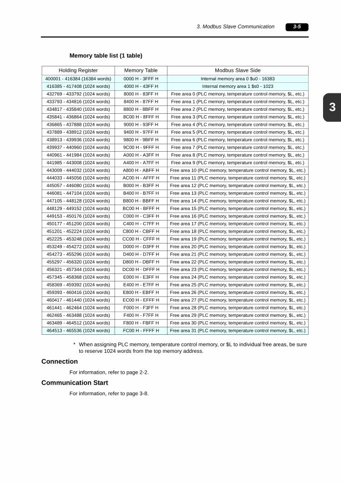
Memory table list (1 table)
* When assigning PLC memory, temperature control memory, or $L to individual free areas, be sure to reserve 1024 words from the top memory address.
ConnectionFor information, refer to page 2-2.
Communication StartFor information, refer to page 3-8.
Holding Register Memory Table Modbus Slave Side400001 - 416384 (16384 words) 0000 H - 3FFF H Internal memory area 0 $u0 - 16383416385 - 417408 (1024 words) 4000 H - 43FF H Internal memory area 1 $s0 - 1023432769 - 433792 (1024 words) 8000 H - 83FF H Free area 0 (PLC memory, temperature control memory, $L, etc.)433793 - 434816 (1024 words) 8400 H - 87FF H Free area 1 (PLC memory, temperature control memory, $L, etc.)434817 - 435840 (1024 words) 8800 H - 8BFF H Free area 2 (PLC memory, temperature control memory, $L, etc.)435841 - 436864 (1024 words) 8C00 H - 8FFF H Free area 3 (PLC memory, temperature control memory, $L, etc.)436865 - 437888 (1024 words) 9000 H - 93FF H Free area 4 (PLC memory, temperature control memory, $L, etc.)437889 - 438912 (1024 words) 9400 H - 97FF H Free area 5 (PLC memory, temperature control memory, $L, etc.)438913 - 439936 (1024 words) 9800 H - 9BFF H Free area 6 (PLC memory, temperature control memory, $L, etc.)439937 - 440960 (1024 words) 9C00 H - 9FFF H Free area 7 (PLC memory, temperature control memory, $L, etc.)440961 - 441984 (1024 words) A000 H - A3FF H Free area 8 (PLC memory, temperature control memory, $L, etc.)441985 - 443008 (1024 words) A400 H - A7FF H Free area 9 (PLC memory, temperature control memory, $L, etc.)443009 - 444032 (1024 words) A800 H - ABFF H Free area 10 (PLC memory, temperature control memory, $L, etc.)444033 - 445056 (1024 words) AC00 H - AFFF H Free area 11 (PLC memory, temperature control memory, $L, etc.)445057 - 446080 (1024 words) B000 H - B3FF H Free area 12 (PLC memory, temperature control memory, $L, etc.)446081 - 447104 (1024 words) B400 H - B7FF H Free area 13 (PLC memory, temperature control memory, $L, etc.)447105 - 448128 (1024 words) B800 H - BBFF H Free area 14 (PLC memory, temperature control memory, $L, etc.)448129 - 449152 (1024 words) BC00 H - BFFF H Free area 15 (PLC memory, temperature control memory, $L, etc.)449153 - 450176 (1024 words) C000 H - C3FF H Free area 16 (PLC memory, temperature control memory, $L, etc.)450177 - 451200 (1024 words) C400 H - C7FF H Free area 17 (PLC memory, temperature control memory, $L, etc.)451201 - 452224 (1024 words) C800 H - CBFF H Free area 18 (PLC memory, temperature control memory, $L, etc.)452225 - 453248 (1024 words) CC00 H - CFFF H Free area 19 (PLC memory, temperature control memory, $L, etc.)453249 - 454272 (1024 words) D000 H - D3FF H Free area 20 (PLC memory, temperature control memory, $L, etc.)454273 - 455296 (1024 words) D400 H - D7FF H Free area 21 (PLC memory, temperature control memory, $L, etc.)455297 - 456320 (1024 words) D800 H - DBFF H Free area 22 (PLC memory, temperature control memory, $L, etc.)456321 - 457344 (1024 words) DC00 H - DFFF H Free area 23 (PLC memory, temperature control memory, $L, etc.)457345 - 458368 (1024 words) E000 H - E3FF H Free area 24 (PLC memory, temperature control memory, $L, etc.)458369 - 459392 (1024 words) E400 H - E7FF H Free area 25 (PLC memory, temperature control memory, $L, etc.)459393 - 460416 (1024 words) E800 H - EBFF H Free area 26 (PLC memory, temperature control memory, $L, etc.)460417 - 461440 (1024 words) EC00 H - EFFF H Free area 27 (PLC memory, temperature control memory, $L, etc.)461441 - 462464 (1024 words) F000 H - F3FF H Free area 28 (PLC memory, temperature control memory, $L, etc.)462465 - 463488 (1024 words) F400 H - F7FF H Free area 29 (PLC memory, temperature control memory, $L, etc.)463489 - 464512 (1024 words) F800 H - FBFF H Free area 30 (PLC memory, temperature control memory, $L, etc.)464513 - 465536 (1024 words) FC00 H - FFFF H Free area 31 (PLC memory, temperature control memory, $L, etc.)

3-6 3. Modbus Slave Communication
Master Setting
The tasks below are required for master settings.
• Specifying a slave memory table number(Note that internal memory ($u, $s) and free area 31 are accessible, irrespective of the memory tables. When accessing these areas, you do not need to specify a table number.)
• Reading the holding register of the slave
• Writing to the holding register of the slave
Applicable Commands
Applicable Memory
*1 Reference number*2 Hexadecimal number
Modbus RTU Format
*1 Broadcast from the master (broadcasting commands to slaves by specifying port No. 00) is not supported.*2 Function code 10 H is used for writing to multiple words of the holding register. For writing to one word of the
holding register, function code 06 H is also usable. In the latter case, defining the number and the byte count is not necessary.
Description Function No. (Code)Read Holding Registers 03 (03 H)Write Single Registers 06 (06 H)
Diagnostics 08 (08 H)Write Multiple Registers 16 (10 H)
Memory Description Function No. (Code)
Holding Register (words)400001 to 465536 *1(0000 to FFFF H) *2
Read Holding Registers 03 (03 H)Write Single Register 06 (06 H)
Write Multiple Registers 16 (10 H)
Reading the holding register
Slave Address XX HFunction Code 03 H
Starting AddressHi XX HLo XX H
No. of RegistersHi XX HLo XX H
Error CheckHi CRC
(16 bits)Lo
*1
Writing to the holding register
Slave Address XX HFunction Code 10 H
Starting AddressHi XX HLo XX H
Quantity of Registers *Hi XX HLo XX H
Byte Count * XX H
Register’s Value 1Hi XX HLo XX H
Register’s Value nHi XX HLo XX H
Error CheckHi CRC
(16 bits)Lo
*1*2
3
3. Modbus Slave Communication 3-7
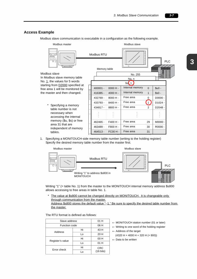
Access ExampleModbus slave communication is executable in a configuration as the following example.
1. Specifying a MONITOUCH-side memory table number (writing to the holding register)Specify the desired memory table number from the master first.
Writing “1” (= table No. 1) from the master to the MONITOUCH internal memory address $s800 allows accessing to free areas in table No. 1.
* The value at $s800 cannot be changed directly on MONITOUCH. It is changeable only through communication from the master.Address $s800 stores the default value “−1.” Be sure to specify the desired table number from the master.
The RTU format is defined as follows:
PLCRESET
discF1
F2
F3
F4
F5
F6
F7
SYSTEM
POWER
Modbus RTU
0
1
0
1
2
29
30
31
0000 H -
4000 H -
8000 H -
8400 H -
8800 H -
F400 H -
F800 H -
FC00 H -
No. 255
400001 -
416385 -
432769 -
433793 -
434817 -
462465 -
463489 -
464513 -
0
1
0
1
2
29
30
31
0000 H -
4000 H -
8000 H -
8400 H -
8800 H -
F400 H -
F800 H -
FC00 H -
No. n
400001 -
416385 -
432769 -
433793 -
434817 -
462465 -
463489 -
464513 -
0
1
0
1
2
29
30
31
0000 H -
4000 H -
8000 H -
8400 H -
8800 H -
F400 H -
F800 H -
FC00 H
No. 0
400001 -
416385 -
432769 -
433793 -
434817 -
462465 -
463489 -
464513
0
1
0
1
2
29
30
31
0000 H -
4000 H -
8000 H -
8400 H -
8800 H -
F400 H -
F800 H -
FC00 H -
No. 1
400001 -
416385 -
432769 -
433793 -
434817 -
462465 -
463489 -
464513 -
$u0 -
$s0 -
D0000 -
D1024 -
D2048 -
M0000 -
R0000 -
Modbus master Modbus slave
Internal memory
Internal memory
Free area
Free area
Free area
Free area
Free area
Free area
Memory table
Modbus slaveIn Modbus slave memory table No. 1, the values for 5 words starting from D2000 specified at free area 1 will be monitored by the master and then changed.
* Specifying a memory table number is not necessary when accessing the internal memory ($u, $s) or free area 31 that are independent of memory tables.
Slave address 01 HFunction code 06 H
AddressHi 43 HLo 20 H
Register’s valueHi 00 HLo 01 H
Error checkHi CRC
(16 bits)Lo
PLCRESET
discF1
F2
F3
F4
F5
F6
F7
SYSTEM
POWER
Modbus RTU
Modbus master Modbus slave
Writing “1” to address $s800 in MONITOUCH
← MONITOUCH station number (01 or later)← Writing to one word of the holding register← Address of the target (4320 H = 4000 H + 320 H (= 800))← Data to be written

3-8 3. Modbus Slave Communication
2. Reading the holding register (MONITOUCH side)Read 5 words starting from address D2000 at free area 1 in table No. 1 from the master.
According to the definition of free area 1 (page 3-8), the accessing target is D2000 = holding register 434769 = hexadecimal No. 87D0 H.The RTU format is defined as follows:
3. Writing to the holding register (slave)Write values to addresses as specified below:
D2000 = 100 (= 64 H)D2001 = 5000 (= 1388 H)D2002 = 1234 (= 4D2 H)D2003 = 789 (= 315 H)D2004 = 200 (= C8 H)
Slave address 01 HFunction code 03 H
Starting addressHi 87 HLo D0 H
No. of registersHi 00 HLo 05 H
Error checkHi CRC
(16 bits)Lo
PLCRESET
discF1
F2
F3
F4
F5
F6
F7
SYSTEM
POWER
Modbus RTU
Modbus master Modbus slave
Reading the values at PLC addresses D2000 to D2004
← MONITOUCH station number (01 or later)← Reading the holding register← Top address D2000 (87D0 H = 34768, 400001+ 34768 = 434769)← Word count
PLCRESET
discF1
F2
F3
F4
F5
F6
F7
SYSTEM
POWER
Modbus RTU
Modbus master Modbus slave
Writing values to 5 words of the PLC memory
D2000 = 100 (= 64 H)D2001 = 5000 (= 1388 H)D2002 = 1234 (= 4D2 H)D2003 = 789 (= 315 H)D2004 = 200 (= C8 H)
3
3. Modbus Slave Communication 3-9
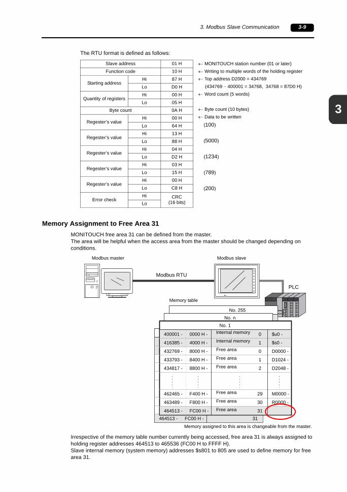
The RTU format is defined as follows:
Memory Assignment to Free Area 31MONITOUCH free area 31 can be defined from the master.The area will be helpful when the access area from the master should be changed depending on conditions.
Irrespective of the memory table number currently being accessed, free area 31 is always assigned to holding register addresses 464513 to 465536 (FC00 H to FFFF H).Slave internal memory (system memory) addresses $s801 to 805 are used to define memory for free area 31.
Slave address 01 HFunction code 10 H
Starting addressHi 87 HLo D0 H
Quantity of registersHi 00 HLo 05 H
Byte count 0A H
Regester’s valueHi 00 HLo 64 H
Regester’s valueHi 13 HLo 88 H
Regester’s valueHi 04 HLo D2 H
Regester’s valueHi 03 HLo 15 H
Regester’s valueHi 00 HLo C8 H
Error checkHi CRC
(16 bits)Lo
← MONITOUCH station number (01 or later)← Writing to multiple words of the holding register← Top address D2000 = 434769 (434769 − 400001 = 34768, 34768 = 87D0 H)← Word count (5 words)
← Byte count (10 bytes)← Data to be written
(100)
(5000)
(1234)
(789)
(200)
PLCRESET
discF1
F2
F3
F4
F5
F6
F7
SYSTEM
POWER
Modbus RTU
0
1
0
1
2
29
30
31
0000 H -
4000 H -
8000 H -
8400 H -
8800 H -
F400 H -
F800 H -
FC00 H -
No. 255
400001 -
416385 -
432769 -
433793 -
434817 -
462465 -
463489 -
464513 -
0
1
0
1
2
29
30
31
0000 H -
4000 H -
8000 H -
8400 H -
8800 H -
F400 H -
F800 H -
FC00 H -
No. n
400001 -
416385 -
432769 -
433793 -
434817 -
462465 -
463489 -
464513 -
0
1
0
1
2
29
30
31
0000 H -
4000 H -
8000 H -
8400 H -
8800 H -
F400 H -
F800 H -
FC00 H -
No. 0
400001 -
416385 -
432769 -
433793 -
434817 -
462465 -
463489 -
464513 -
0
1
0
1
2
29
30
31
0000 H -
4000 H -
8000 H -
8400 H -
8800 H -
F400 H -
F800 H -
FC00 H -
No. 1
400001 -
416385 -
432769 -
433793 -
434817 -
462465 -
463489 -
464513 -
$u0 -
$s0 -
D0000 -
D1024 -
D2048 -
M0000 -
R0000 -
Modbus master Modbus slave
Internal memory
Internal memory
Free area
Free area
Free area
Free area
Free area
Free area
Memory table
Memory assigned to this area is changeable from the master.

3-10 3. Modbus Slave Communication
System Memory ($s)The settings of the system memory depend on the type of memory to be defined.
• MONITOUCH internal memory ($u, $s, $L/$LD (0 - 65535))PLC memory (0 - 65535)Temperature control/PLC2Way memory (0 - 65535)
• MONITOUCH internal memory ($L/$LD (65536 or later))PLC memory (65536 or later)Temperature control/PLC2Way memory (65536 or later)
- Model, memory type (HEX)
- Extension code (HEX)Set an extension code when you specify a SPU memory slot number for a Mitsubishi PLC, etc.Ex.:Mitsubishi: Slot No. 0: 00 HMitsubishi: Slot No. 1: 01 HYokogawa: CPU No. 1: 00 HYokogawa: CPU No. 2: 01 HJTEKT: PRG No. 1: 00 HJTEKT: PRG No. 2: 01 H
- Port No. (HEX)1:1 or multi-link: Not usedMulti-drop: Set the PLC station number.Temperature controller: Set the temperature controller station number.
System MemoryDescription
15 (MSB) 8 7 (LSB) 0$s801 Model Memory type$s802 Top memory number (address)$s803 Extension code 00 H$s804 00 H Station number$s805 00 H
System MemoryDescription
15 (MSB) 8 7 (LSB) 0$s801 Model Memory type$s802 Top memory number (address) lower-order$s803 Top memory number (address) higher-order$s804 Extension code 00 H$s805 00 H Station number
Model Memory Type
Internal memory
$u00
00$s 01
$L0 - 65535
0265536 - 80
$LD0 - 65535 00
0365536 - 80
$T 0 - 1023 00 04
PLC memory0 - 65535 01 The memory type depends on the PLC or
memory used. Refer to the PLC Connection Manual and set the type of the memory.65536 - 81
Temperature control
memory
0 - 65535 03 The memory type depends on the memory used. Refer to the Temperature Control Network Manual and set the type number of the memory.65536 - 83
3
3. Modbus Slave Communication 3-11
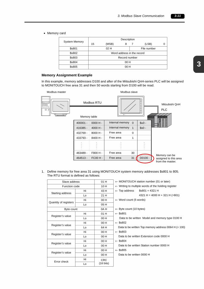
• Memory card
Memory Assignment ExampleIn this example, memory addresses D100 and after of the Mitsubishi QnH-series PLC will be assigned to MONITOUCH free area 31 and then 50 words starting from D100 will be read.
1. Define memory for free area 31 using MONITOUCH system memory addresses $s801 to 805.The RTU format is defined as follows:
System MemoryDescription
15 (MSB) 8 7 (LSB) 0$s801 02 H File number$s802 Word address in the record$s803 Record number$s804 00 H$s805 00 H
PLCRESET
discF1
F2
F3
F4
F5
F6
F7
SYSTEM
POWER
Modbus RTU
0
1
0
1
30
31
0000 H -
4000 H -
8000 H -
8400 H -
F800 H -
FC00 H -
400001 -
416385 -
432769 -
433793 -
463489 -
464513 -
$u0 -
$s0 -
D0100 -
Modbus master Modbus slave
Internal memory
Internal memory
Free area
Free area
Free area
Free area
Memory table
Memory can be assigned to this area from the master.
Mitsubishi QnH
Slave address 01 HFunction code 10 H
Starting addressHi 43 HLo 21 H
Quantity of registersHi 00 HLo 05 H
Byte count 0A H
Register’s valueHi 01 HLo 00 H
Register’s valueHi 00 HLo 64 H
Register’s valueHi 00 HLo 00 H
Register’s valueHi 00 HLo 00 H
Register’s valueHi 00 HLo 00 H
Error checkHi CRC
(16 bits)Lo
← MONITOUCH station number (01 or later)← Writing to multiple words of the holding register← Top address $s801 = 4321 H
4321 H = 4000 H + 321 H (=801)← Word count (5 words)
← Byte count (10 bytes)← $s801 Data to be written Model and memory type 0100 H← $s802 Data to be written Top memory address 0064 H (= 100)← $s803 Data to be written Extension code 0000 H← $s804 Data to be written Station number 0000 H← $s805 Data to be written 0000 H

3-12 3. Modbus Slave Communication
2. Read 50 words starting from the assigned D100.The RTU format is defined as follows:
Notes• Memory assignment to free area 31 is allowed when MONITOUCH is in the state of RUN.
When MONITOUCH is brought to the state of STOP, the assigned memory will be cleared.When you wish to use free area 31, be sure to assign memory at each start of the master-MONITOUCH communication.
• Definition at $s800 to 805 cannot be changed directly on MONITOUCH. It is changeable only through communication from the master.
• When setting a timeout period for the master associated with Modbus slave communication, the processing time (cycle time) required on MONITOUCH side should be taken into account.
Ex.)When a processing time (cycle time) required between MONITOUCH and the PLC is approximately 150 ms:
The timeout period required on the master side is 150 ms or longer.For the additional time “+α” a processing time between the master and MONITOUCH should be considered.This processing time is determined by the amount of data to be accessed at one time.If the amount of data increases, the timeout period should also be increased appropriately.
Slave address 01 HFunction code 03 H
Starting addressHi FC HLo 00 H
Quantity of registersHi 00 HLo 32 H
Error checkHi CRC
(16 bits)Lo
← MONITOUCH station number (01 or later)← Reading the holding register← Top address Top address at free area 31 FC00 H← Word count 50 (32 H)
RESET
discF1
F2
F3
F4
F5
F6
F7
SYSTEM
POWER
Modbus master Modbus slave
Timeout: (150 ms) + α 150 ms
4
4. Use of MONITOUCH as Modbus Master 4-1
4. Use of MONITOUCH as Modbus Master
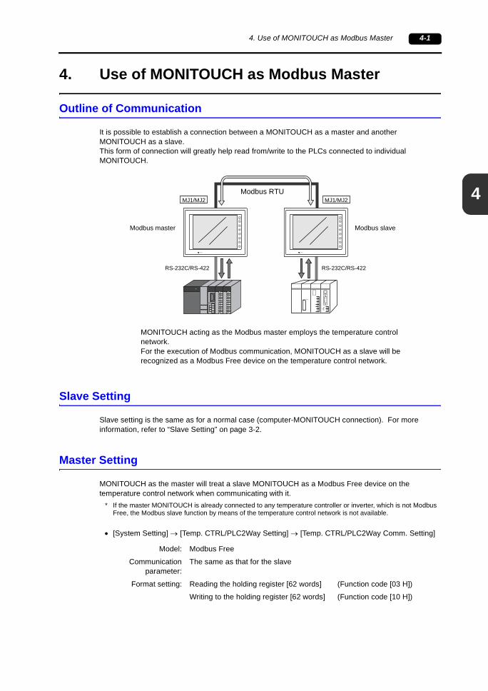
Outline of Communication
It is possible to establish a connection between a MONITOUCH as a master and another MONITOUCH as a slave.This form of connection will greatly help read from/write to the PLCs connected to individual MONITOUCH.
Slave Setting
Slave setting is the same as for a normal case (computer-MONITOUCH connection). For more information, refer to “Slave Setting” on page 3-2.
Master Setting
MONITOUCH as the master will treat a slave MONITOUCH as a Modbus Free device on the temperature control network when communicating with it.
* If the master MONITOUCH is already connected to any temperature controller or inverter, which is not Modbus Free, the Modbus slave function by means of the temperature control network is not available.
• [System Setting] → [Temp. CTRL/PLC2Way Setting] → [Temp. CTRL/PLC2Way Comm. Setting]
RS-232C/RS-422
Modbus RTU
F1
F2
F3
F4
F5
F6
F7
SYSTEM
POWER
F1
F2
F3
F4
F5
F6
F7
SYSTEM
POWER
MJ1/MJ2 MJ1/MJ2
PROGRAMMER
RS-232C/RS-422
Modbus master Modbus slave
MONITOUCH acting as the Modbus master employs the temperature control network.For the execution of Modbus communication, MONITOUCH as a slave will be recognized as a Modbus Free device on the temperature control network.
Model: Modbus Free
Communicationparameter:
The same as that for the slave
Format setting: Reading the holding register [62 words] (Function code [03 H])
Writing to the holding register [62 words] (Function code [10 H])
4-2 4. Use of MONITOUCH as Modbus Master
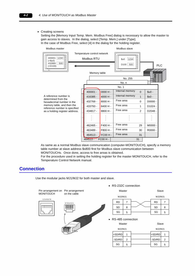
• Creating screensSetting the [Memory Input Temp. Mem. Modbus Free] dialog is necessary to allow the master to gain access to slaves. In the dialog, select [Temp. Mem.] under [Type].In the case of Modbus Free, select [4] in the dialog for the holding register.
As same as a normal Modbus slave communication (computer-MONITOUCH), specify a memory table number at slave address $s800 first for Modbus slave communication between MONITOUCHs. Once done, access to free areas is obtained.For the procedure used in setting the holding register for the master MONITOUCH, refer to the Temperature Control Network manual.
Connection
Use the modular jacks MJ1/MJ2 for both master and slave.
PLC
F1
F2
F3
F4
F5
F6
F7
SYSTEM
POWER
Modbus RTU
0
1
0
1
2
29
30
31
0000 H -
4000 H -
8000 H -
8400 H -
8800 H -
F400 H -
F800 H -
FC00 H -
No. 255
400001 -
416385 -
432769 -
433793 -
434817 -
462465 -
463489 -
464513 -
0
1
0
1
2
29
30
31
0000 H -
4000 H -
8000 H -
8400 H -
8800 H -
F400 H -
F800 H -
FC00 H -
No. n
400001 -
416385 -
432769 -
433793 -
434817 -
462465 -
463489 -
464513 -
0
1
0
1
2
29
30
31
0000 H -
4000 H -
8000 H -
8400 H -
8800 H -
F400 H -
F800 H -
FC00 H -
No. 0
400001 -
416385 -
432769 -
433793 -
434817 -
462465 -
463489 -
464513 -
0
1
0
1
2
29
30
31
0000 H -
4000 H -
8000 H -
8400 H -
8800 H -
F400 H -
F800 H -
FC00 H -
No. 1
400001 -
416385 -
432769 -
433793 -
434817 -
462465 -
463489 -
464513 -
$u0 -
$s0 -
D0000 -
D1024 -
D2048 -
M0000 -
R0000 -
F1
F2
F3
F4
F5
F6
F7
SYSTEM
POWER
$u0 1234
D100 500
400001 1234(=$u0)432869 500(=D100)
Modbus master Modbus slave
Internal memory
Internal memory
Free area
Free area
Free area
Free area
Free area
Free area
Memory table
A reference number is determined from the hexadecimal number in the memory table, and then the reference number is specified as a holding register address.
Temperature control network
12345678
87654321
+SD/RD
-SD/RD
SG
1
2
5
MJ2/MJ1
7
8
5
RD
SD
SG
MJ2/MJ1
+SD/RD
-SD/RD
SG
1
2
5
MJ2/MJ1
7
8
5
RD
SD
SG
MJ2/MJ1
MasterPin arrangement on MONITOUCH
SlavePin arrangement on the cable
• RS-232C connection
Master Slave• RS-485 connection
4
4. Use of MONITOUCH as Modbus Master 4-3
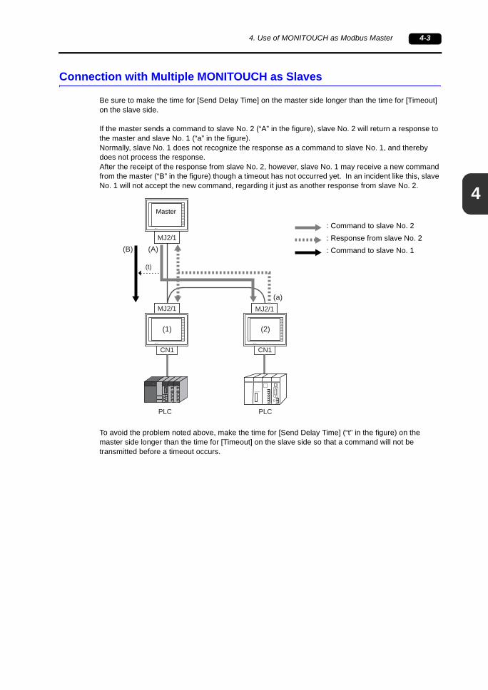
Connection with Multiple MONITOUCH as Slaves
Be sure to make the time for [Send Delay Time] on the master side longer than the time for [Timeout] on the slave side.
If the master sends a command to slave No. 2 (“A” in the figure), slave No. 2 will return a response to the master and slave No. 1 (“a” in the figure).Normally, slave No. 1 does not recognize the response as a command to slave No. 1, and thereby does not process the response.After the receipt of the response from slave No. 2, however, slave No. 1 may receive a new command from the master (“B” in the figure) though a timeout has not occurred yet. In an incident like this, slave No. 1 will not accept the new command, regarding it just as another response from slave No. 2.
To avoid the problem noted above, make the time for [Send Delay Time] (“t” in the figure) on the master side longer than the time for [Timeout] on the slave side so that a command will not be transmitted before a timeout occurs.
(A)(B)
MJ2/1 MJ2/1
CN1 CN1
MJ2/1
(t)
(a)
PLC PLC
F1
F2
F3
F4
F5
F6
F7
SYSTEM
POWER
F1
F2
F3
F4
F5
F6
F7
SYSTEM
POWER
PROGRAMMER
F1
F2
F3
F4
F5
F6
F7
SYSTEM
POWER
(1) (2)
: Command to slave No. 2: Response from slave No. 2: Command to slave No. 1
Master
4-4 4. Use of MONITOUCH as Modbus Master
Please use this page freely.
5
5. Appendix 5-1
5. Appendix
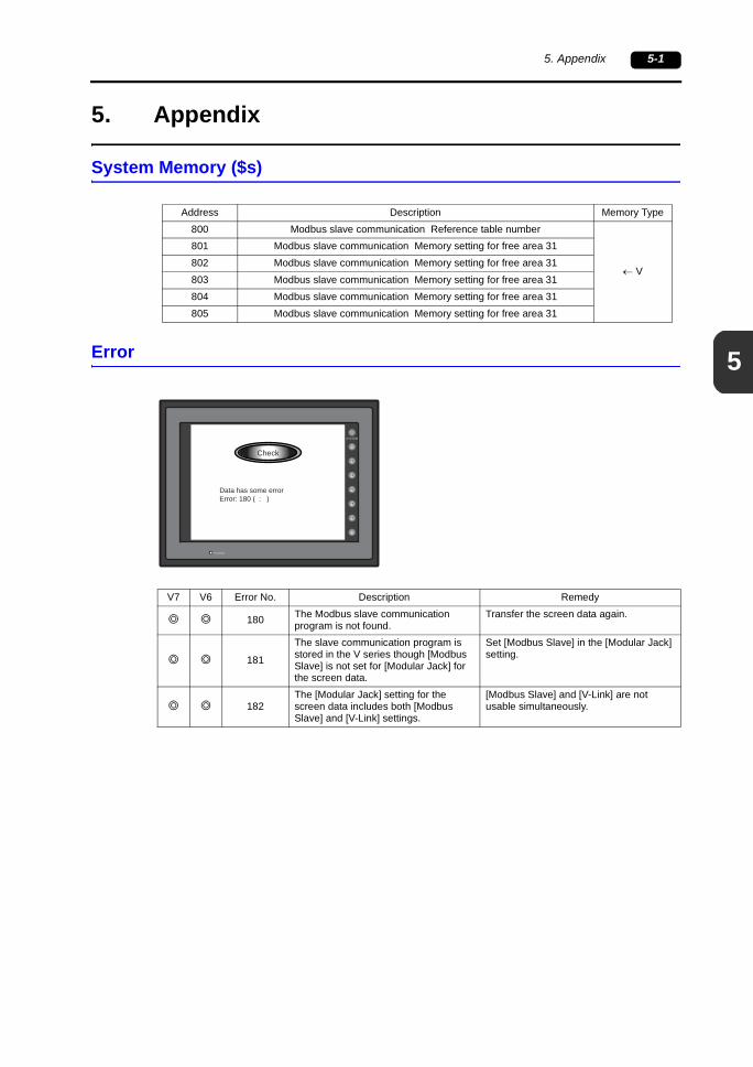
System Memory ($s)
Error
Address Description Memory Type800 Modbus slave communication Reference table number
← V
801 Modbus slave communication Memory setting for free area 31802 Modbus slave communication Memory setting for free area 31803 Modbus slave communication Memory setting for free area 31804 Modbus slave communication Memory setting for free area 31805 Modbus slave communication Memory setting for free area 31
Data has some errorError: 180 ( : )
Check
V7 V6 Error No. Description Remedy
180 The Modbus slave communication program is not found.
Transfer the screen data again.
181
The slave communication program is stored in the V series though [Modbus Slave] is not set for [Modular Jack] for the screen data.
Set [Modbus Slave] in the [Modular Jack] setting.
182The [Modular Jack] setting for the screen data includes both [Modbus Slave] and [V-Link] settings.
[Modbus Slave] and [V-Link] are not usable simultaneously.

5-2 5. Appendix
Please use this page freely.

607000001046NE0
Hakko Electronics Co., Ltd.890-1, Kamikashiwano-machi, Hakusan-shi, Ishikawa, 924-0035 JapanTEL +81-76-274-2144 FAX +81-76-274-5208
TEL +81-3-5767-6160 FAX +81-3-5767-6170
TEL +81-82-568-0905 FAX +81-82-568-0922
Tokyo Office
Hiroshima Office
Sales
TEL +81-6-6385-8234 FAX +81-6-6385-7851Osaka Office
TEL +81-52-789-0096 FAX +81-52-789-0098Nagoya Office