green line cmx - polypipe · green line cmx central mechanical extract ventilation (cmev) appliance...
TRANSCRIPT
LAB964R, Issue 4, May 2014 Page 1
Green Line CMX
Central Mechanical Extract Ventilation (cMEV) appliance
Installation and Operating Instructions
Model: CMX
These instructions must be given to the householder
DO NOT SWITCH OFF THE UNIT – it is designed to run continuously. If the unit is switched off, indoor pollutants and moisture levels may increase which could endanger your health or damage your home.
It is important to follow the advice in this manual and correctly maintain
the system to ensure a healthy indoor environment.

LAB964R, Issue 4, May 2014 Page 2
Warnings & Safety Information IMPORTANT! PLEASE READ THESE INSTRUCTIONS CAREFULLY BEFORE COMMENCING INSTALLATION 1. Do not install this appliance in areas where the following may be present or occur:
• Excessive oil or a grease laden atmosphere • Corrosive or flammable gases, liquids or vapours
• Be subject to direct water spray • Ambient temperatures higher than 50ºC and lower than -25ºC • Possible obstructions that may hinder access or removal of the unit
2. This appliance is not intended for use by young children or infirm persons without adequate supervision. 3. All wiring must be in accordance with prevailing national regulations, for example the current IEE Wiring Regulations BS7671. The electrical installation should be inspected and tested by a suitably qualified person after completion. 4. The appliance should be provided with a local double pole fused spur fitted with a 3 Amp fuse and a minimum contact separation of at least 3mm. 5. Ensure that the mains supply (Voltage and Frequency) complies with the rating label. 6. This appliance must be earthed. 7. When installing the appliance, care should be taken not to damage any hidden utilities. 8. The installer is responsible for the installation and electrical connection of the CMX system on site. It is the responsibility of the installer to ensure that the equipment is safely and securely installed and left only when electrically and mechanically safe. 9. All regulations and requirements must be strictly followed to prevent hazards to life and property, both during and after installation and any subsequent servicing or maintenance. 10. In dwellings where it is intended to install open-flue appliances and extract ventilation, the combustion appliance should be able to operate safely, whether or not the fans are running. A way of showing compliance with The Building Regulations in these circumstances would be to follow the installation guidance shown below, and to show by tests that combustion appliances operate safely, whether or not the fans are running.
A. For gas appliances: where a room contains an open-flue appliance, the extract rate should not exceed 20l/s (72m³/h).
B. For oil appliances: where a room contains an open-flue appliance, the extract rate should be limited to 40l/s (144m³/h) for an appliance with a pressure jet burner and 20l/s (72m³/h) for an appliance with a vaporising burner.
C. For solid fuel appliances: avoid installing extract ventilation in the same room.
Further reference should be made to Approved Document J of The Building Regulations. 11. This appliance should not be directly connected to a tumble dryer or cooker hood. 12. A supply of fresh replacement air must be drawn from the exterior of the property. Further reference should be made to Approved Document F of The Building Regulations. 13. The extracted air must be expelled to the exterior of the property. 14. Extract ceiling valves should be positioned at least 300mm from internal walls to allow airflow measuring equipment to fit correctly over the valves. 15. Ducting should be insulated where it passes through unheated spaces and voids (e.g. loft spaces) to reduce the possibility of condensation forming.

LAB964R, Issue 4, May 2014 Page 3
Contents Warnings & Safety Information 1. General description Page 4 2. Physical specification Page 5 3. Installation Page 5 4. Ducting guidelines Page 6 5. Electrical Page 7 6. Wiring Page 7 7. Remote switch wiring diagrams Page 8 8. External sensor wiring diagrams Page 9 9. Commissioning Page 10 10. System balancing Page 10 11. Maintenance Page 10 12. Warranty Page 11

LAB964R, Issue 4, May 2014 Page 4
1 General description 1.1 The Silavent CMX appliance is a key part of a whole house ventilation system specifically designed to
improve indoor air quality in dwellings. The system is designed to remove polluted, stale air from all bathing, cooking and washing areas at a constant gentle rate. Fresh replacement air is supplied through background ventilators installed in all living areas (supplied separately – see section 1.5).
1.2 A manual boost switch can be used to increase the ventilation rate, e.g. when cooking or showering
thereby maintaining a comfortable indoor environment (supplied separately – see section 1.6). 1.3 The boost facility can also be triggered from a lighting circuit or by a range of sensors, including
humidity control and PIR movement detection (supplied separately – see section 1.7). 1.4 This product is listed in the Products Characteristics Database (PCDB), therefore part of the installation
process requires that an installation checklist is completed and submitted to the Building Control Body (BCB). Blank checklists are available at www.ncm-pcdb.org.uk/SAP. The NCM (SAP) identifier for this product is Silavent CMX.
1.5 Ancillary items required:
• Domus 220mm x 90mm rectangular or Ø150mm round rigid duct system (adaptor req) (see 5.2)
• Domus CMX-ASK1 or Domus 2404 air supply kits with filter (see 1.1)
1.6 Control switch options – supplied separately (wiring - see page 6)
• Silavent manual LOW/BOOST switch, code ANC848A Manual BOOST selection switch. LOW speed is engaged upon connection of mains supply. Both speeds are manually adjustable at the wiring centre to facilitate Building Regulation commissioning speeds.
• Silavent manual OCCUPIED/UNOCCUPIED - LOW/BOOST switch, code ANC849A Manual BOOST and UNOCCUPIED selection switches. OCCUPIED/LOW speed is engaged upon connection of mains supply. UNOCCUPIED speed is intended to be lower than the OCCUPIED/LOW Building Regulation commissioning speed and should only be selected when the property is vacant for extended periods such as holidays in order to save energy but keep the property ‘fresh’. There is no requirement or value in the Building Regulations for this speed, so it should be set to suit the individual client’s requirement. All three speeds are manually adjustable at the wiring centre to facilitate Building Regulation commissioning speeds.
• Silavent manual LOW/BOOST/PURGE switch, code ANC850A Manual BOOST and PURGE selection switches. LOW speed is engaged upon connection of mains supply. PURGE speed is intended to be higher than the BOOST Building Regulation commissioning speed and should be selected during periods when exceptional levels of indoor pollution are encountered such overcooked food or paint fumes. The Building Regulations recommend a 4ach (air change per hour) air flow rate for this speed but should be set to suit the individual client’s requirement. All three speeds are manually adjustable at the wiring centre to facilitate Building Regulation commissioning speeds.
1.7 Remote/automatic control options – supplied separately (wiring - see page 7)
• Silavent adjustable overrun timer, code ANC108A
• Silavent humidity control with adjustable overrun timer, code ANC802A
• Silavent humidity control with adjustable overrun timer and remote sensor, code ANC846A
• Silavent humidity control with adjustable overrun timer and manual override with neon indicator, code ANC808A
• Silavent PIR movement control with adjustable overrun timer, code ANC813A
• Silavent 6-Switched live backfeed protected junction box, code ELE150R
LAB964R, Issue 4, May 2014 Page 5
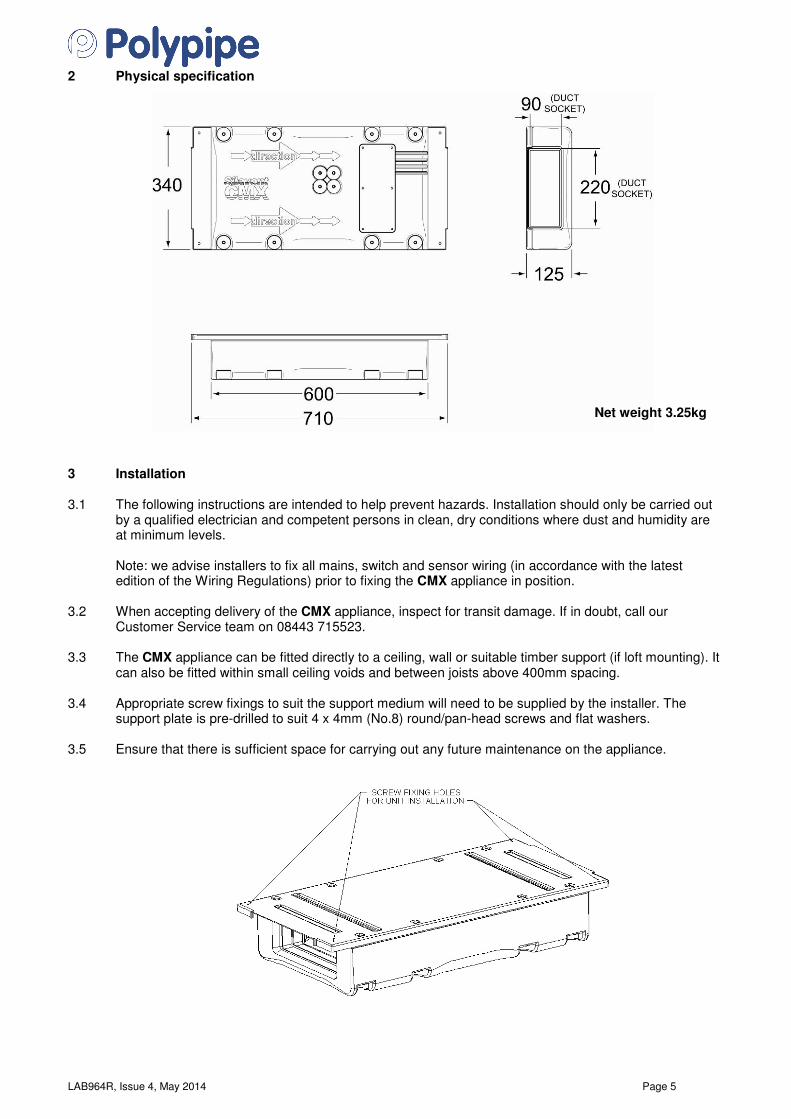
2 Physical specification
Net weight 3.25kg
3 Installation 3.1 The following instructions are intended to help prevent hazards. Installation should only be carried out
by a qualified electrician and competent persons in clean, dry conditions where dust and humidity are at minimum levels.
Note: we advise installers to fix all mains, switch and sensor wiring (in accordance with the latest
edition of the Wiring Regulations) prior to fixing the CMX appliance in position. 3.2 When accepting delivery of the CMX appliance, inspect for transit damage. If in doubt, call our
Customer Service team on 08443 715523. 3.3 The CMX appliance can be fitted directly to a ceiling, wall or suitable timber support (if loft mounting). It
can also be fitted within small ceiling voids and between joists above 400mm spacing. 3.4 Appropriate screw fixings to suit the support medium will need to be supplied by the installer. The
support plate is pre-drilled to suit 4 x 4mm (No.8) round/pan-head screws and flat washers. 3.5 Ensure that there is sufficient space for carrying out any future maintenance on the appliance.
LAB964R, Issue 4, May 2014 Page 6
4 Ducting guidelines 4.1 Please refer to the dwelling’s design drawings for the proposed ducting layout. 4.2 Two 220mm x 90mm sockets are provided for connecting the ducting. Domus rigid ductwork should be
securely connected to the sockets using Domus DDSEAL acrylic sealant; failure to do this will cause unnecessary air leakage and impair performance. Important: Using the arrows moulded into the body of the CMX appliance as a guide, ensure that the direction of airflow is from the ‘wet rooms’ to the outside.
4.3 Ducting attached to the appliance must be supported adjacent to the appliance using Domus 922Domus 922Domus 922Domus 922
support clips. This is important for major maintenance or end of life replacement to ensure that the ducting is adequately supported if the CMXCMXCMXCMX body is removed.
4.4 Where ducting passes through unheated areas and voids (e.g. loft spaces) it must be insulated in order
to comply with Approved Document F of The Building Regulations. 4.5 When passing through a fire-stopping wall or fire-compartment wall, Domus FireBrake intumescent
duct connectors should be used in order to comply with Approved Document B of The Building Regulations.
4.6 Alternative proprietary fire-stopping methods may be employed provided they comply with Approved
Document B of The Building Regulations. 4.7 Rigid ducting – install using the least number of fittings to minimise resistance to airflow. All duct runs
should be as short and as straight as possible for maximum performance. 4.8 Semi-rigid (Domus Radial) ducting – instructions available on request or available to download at
www.polypipe.com/ventilation – see also 4.1. 4.9 The stale extract air must be expelled to the exterior of the property. If expelled through a wall, a
Domus 905 airbrick should be fitted. If expelled through the roof a Domus 4411 universal roof terminal should be fitted or a proprietary roof terminal designed for mechanical ventilation with a free area of at least 15175mm².
4.10 Further details regarding installation can be found in the 2010 Domestic Ventilation Compliance Guide.

LAB964R, Issue 4, May 2014 Page 7
5 Electrical 5.1 WARNING: This appliance must be earthed. 5.2 Important: All wiring must be carried out by a qualified electrician and conform to the prevailing
national regulations, for example the latest edition of BS7671: IEE Wiring Regulations. 5.3 This appliance is suitable for 230V 50Hz single phase supply only, fused at 3 Amps. 5.4 A double-pole switch having a minimum contact separation of 3mm must be used to provide isolation
for the appliance. 5.5 Sensor diagrams are shown on page 9. 5.6 External wiring (1.5mm² max.) and isolators to be supplied by others. 6 Wiring 6.1 Remove the cover of the wiring centre by removing the six retaining screws while taking care not to
dislodge any of the pre-wired cables. 6.2 Make the wiring connections – see diagram below. 6.3 Refit the wiring centre cover.

LAB964R, Issue 4, May 2014 Page 8
7 Remote switch wiring diagrams - ANC848A, ANC849A, ANC850A
ANC848A Low & Boost functions
ANC850A Low, Boost & Purge
functions
ANC849A Occupied/
Unoccupied, Low & Boost functions
BOOST PURGE
BOOST UNOCCUPIED
LAB964R, Issue 4, May 2014 Page 9
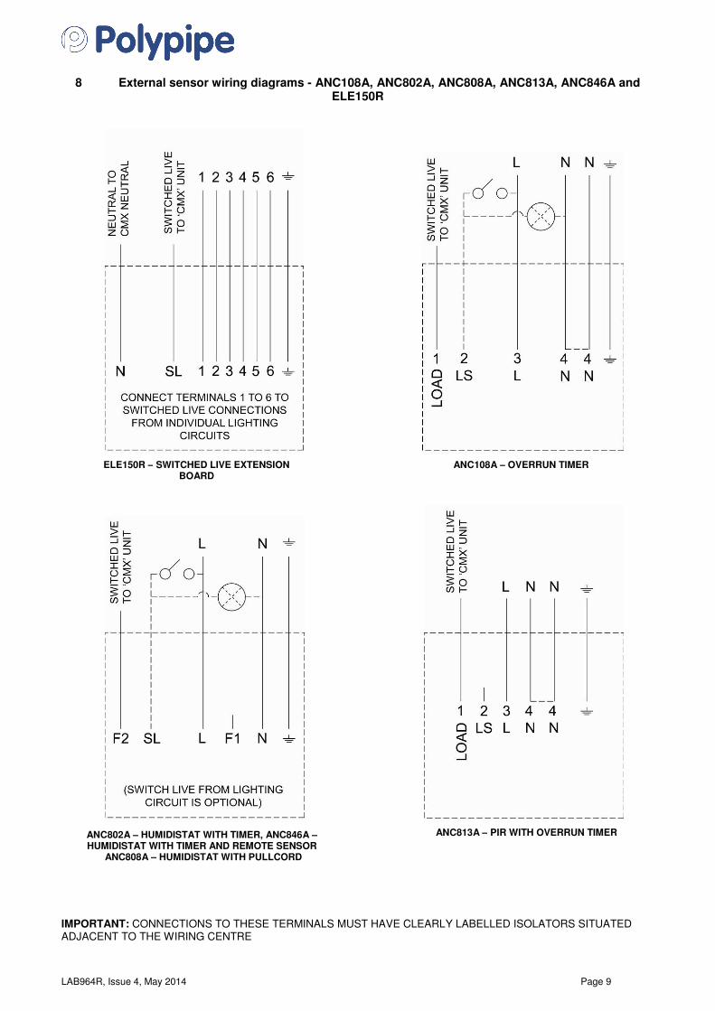
8 External sensor wiring diagrams - ANC108A, ANC802A, ANC808A, ANC813A, ANC846A and ELE150R
IMPORTANT: CONNECTIONS TO THESE TERMINALS MUST HAVE CLEARLY LABELLED ISOLATORS SITUATED ADJACENT TO THE WIRING CENTRE
ANC108A – OVERRUN TIMER
ELE150R – SWITCHED LIVE EXTENSION
BOARD
ANC802A – HUMIDISTAT WITH TIMER, ANC846A – HUMIDISTAT WITH TIMER AND REMOTE SENSOR
ANC808A – HUMIDISTAT WITH PULLCORD
ANC813A – PIR WITH OVERRUN TIMER
LAB964R, Issue 4, May 2014 Page 10
9 Commissioning 9.1 When the wiring connections have been checked, switch on the mains supply and check that the
system is operating correctly. The appliance should switch between low and boost speeds using the chosen manual boost switch (see 1.2). Check other switch and sensor functions are operating correctly.
9.2 To balance the system, airflow rates will need to be set at each room’s air valve in accordance with the
2010 Domestic Ventilation Compliance Guide. Airflow measurements should be performed using a calibrated airflow measuring device and the results recorded in litres per second (l/s) onto the Inspection Checklist and Airflow Measurement Test Sheet contained within the 2010 Domestic Ventilation Compliance Guide. The most common method uses a vane anemometer, or similar, placed in a hood which completely covers the air valve to measure the extract or supply airflow rate. The instrument should be calibrated annually by returning the instrument to a UKAS accredited calibration centre and be capable of achieving an accuracy of ±5%. We recommend using Polypipe’s CM01 vane anemometer. Please call our Customer Service team on 08443 715523 for more information or visit www.polypipe.com/ventilation/ventilation-installer-training.
9.3 Each room airflow rate will need to be recorded on the Inspection Checklist and Airflow Measurement
Test Sheet. A completed copy must accompany these instructions and be handed over to the dwelling’s owner upon completion of the installation.
10 System balancing
• Fully open all of the air valves
• Switch the system to boost
• Close all internal and external doors and windows
• Measure the total air volume of the extract valves (wet rooms)
• Remove the rubber tamper-deterrent cap and using a small screwdriver, adjust the ‘boost’ control on the wiring centre to achieve the whole dwelling extract ventilation rate
• Adjust individual room air valves to achieve the individual room boost extract rates
• Switch the system to low
• Measure the total air volume of the valves
• Remove the rubber tamper-deterrent cap and using a small screwdriver, adjust the ‘low’ control on the wiring centre to achieve the whole dwelling ventilation rate
• Using the lock nuts fitted to the air valves, lock in position
• Refit the rubber tamper deterrent caps to the lid of the wiring centre 11 Maintenance 11.1 The CMX appliance is essentially maintenance free; however, if necessary the main body can be
removed from the ducting for periodic cleaning as follows: 11.2 Isolate and disconnect the power supply. 11.3 Remove the 8 x M8 dome nuts and mudguard washers and remove the body from the retained bolts
and ducting. 11.4 Clean out the body using a brush, dry cloth or vacuum cleaner. 11.5 Reassemble and reconnect to the power supply.

LAB964R, Issue 4, May 2014 Page 11
12 Warranty
LIMITED TWO YEAR WARRANTY In the event that any problem or fault develops with the product due to faulty materials or workmanship during the two year period beginning on the date on which you purchased the product then subject to the various limitations and exclusions as detailed below, Polypipe will as soon as reasonably possible either repair or replace the product during its usual working hours or, at Polypipe’s discretion, provide you with a refund of the purchase price which you paid for the product. If you need to make a claim under this warranty then please contact Polypipe using one of the following methods:
Polypipe Ventilation Sandall Stones Road Kirk Sandall Industrial Estate Kirk Sandall, Doncaster DN3 1QR, UK
Tel: 08443 715523 Fax: 08443 715524 International Tel: +44 (0)1302 348878 International Fax: +44 (0)1302 348879
Email: [email protected]
The above warranty does not apply to nor cover the repair of any problem or fault with the product which arises as a result of: (a) failure to install, operate, maintain and/or repair the product or any associated parts and components (including any ducting) using reasonable skill and care and in accordance with the instructions provided with it (unless the original installation, maintenance or repair which gave rise to the problem or fault was carried out by or on the behalf of Polypipe in which case this exclusion will not apply); (b) use of the product for any purposes other than those for which it is designed; (c) modifications made to the product by anyone other than Polypipe or its approved contractors; (d) deliberate damage; and/or (e) damage caused by fire, flood or other water damage, explosions, rust or corrosion. Polypipe may carry out the repair or replacement of the product itself or using an approved sub-contractor but will always remain liable to you for the acts or omissions of any such sub-contractor as if those were the acts or omissions of Polypipe itself. Where you have purchased the product acting in your capacity as a consumer then the above warranty is offered by Polypipe in addition to and is not intended to affect or lessen those statutory rights which you became entitled to as a consumer when you purchased the product. In the UK you can find out more about your rights as a consumer by visiting the website of the Citizen’s Advice Bureau (http://www.adviceguide.org.uk/england/consumer_e.htm).

LAB964R, Issue 4, May 2014 Page 12
Installer contact details:
Company name:
Contact:
Tel:
Email: Polypipe Ventilation Sandall Stones Road Kirk Sandall Industrial Estate Kirk Sandall Doncaster DN3 1QR UK Tel: 08443 715523 Fax: 08443 715524 International Tel: +44 (0)1302 348878 International Fax: +44 (0)1302 348879 Email: [email protected] Web: www.polypipe.com/ventilation E&OE