grepl, r. modelling and control of electromechanical servo system...
TRANSCRIPT

Modelling and Control of Electromechanical Servo System with High Nonlinearity 45
Modelling and Control of Electromechanical Servo System with High Nonlinearity
Grepl, R.
x
Modelling and Control of Electromechanical Servo System with High Nonlinearity
Grepl, R.
Mechatronic Laboratory, ISMMB, Faculty of Mechanical Engineering Brno University of Technology, Czech Republic,
[email protected], http://www.umt.fme.vutbr.cz/rgrepl
1. Introduction
Electromechanical servo plays important role in automation, robotics and automotive industry. Recent passenger cars are equipped with dozens of such actuators. Often, these actuators replace the original manual and/or mechanical solution by so called mechatronic design –mechanism, electric motor and computer control. Typical example of mechatronic design is the throttle for airflow control of a combustion engine. Conventional mechanical linkage between the driver pedal and the throttle using Bowden cable is in recent cars replaced by the pedal sensor, throttle body (with DC motor, spur gears and potentiometer as position sensor) and the electronic control unit (ECU). The pedal is connected to the throttle only by means of “wire”; therefore this approach is generally called dribe-by-wire or X-by-wire. The research and development is very active in the field of steering-by-wire and brake-by-wire. Due to mass production of automotive parts and related relatively low technical quality, the dry friction is very significant in the actuator. The software implementation of position control in ECU can be challenging and interesting issue if the fast and precise response is required. Moreover, the additional strong spring nonlinearities can complicate the control as we see further.
Fig. 1. Block diagram of Electronic Throttle Control
3
www.intechopen.com

Mechatronic Systems, Simulation, Modelling and Control46
This chapter deals with the control of electromechanical servo with significant dry friction. This topic has been extensively studied with following main results:
As it is well known, the PID controller cannot be successfully used for system with nonlinearity of dry friction type (Isermann, 1996).
The nonlinear compensator should be used as a part of controller. In most cases this compensator is based on the knowledge of system model. If Sliding Mode Control is used, only the upper bound of the friction must be known (Beghi et al., 2006; Zhang et al., 2006).
The friction compensation naturally requires the velocity measurement or good estimation from measured position (Olsson, 1996). Alternatively, the position error is used for compensation which leads to more robust behaviour and eliminate the serious problem with velocity estimation (Isermann et al., 1991 ; Yang 2004; Pavković et al. 2006).
In the last decade, there have been published many interesting results dealing particularly with electronic throttle control. The papers published by Pavković, Deur, and Vašak (Pavković et al. 2006, Deur et al. 2003, Vašak et al. 2007) present the controller consisting of friction compensator, LH compensator, and PID. In (Deur et al. 2003) the self tuning of compensator parameters is described.
The development and testing of two new types of nonlinear controllers designed for particular type of reference signal is presented in this chapter. The combination of PID with feedforward and feedback compensators is successfully used. The performance is measured by multiple criteria. The modular dSPACE Rapid Control Prototyping hardware is used for both parameter estimation as well as control experiments.
2. Modelling of nonlinear electromechanical servo
Modelling of any kind of system can be based on one of following two main principles: Modelling from fundamental physical principles – This approach can be used if
the physical laws describing the system behaviour is known and equations can be derived. Both linear and nonlinear phenomenon can be modelled including e.g. non-smooth dynamics. Usually, remaining problems are: a) parameter estimation of proposed model; b) validation of the model. A good example of such system is the pendulum, where the equation is easy to derive, but e.g. the viscous damping parameter could be difficult to guess. Moreover, when the model is validated using experimental data measured on real pendulum, the dry friction can appears significant and model must be reformulated.
Modelling from measured data – If the system physics is unknown or difficult to express, the model can be derived from experimental data measured on real system. The linear discrete time model with particular noise model is usually assumed and the identification algorithm searches for its coefficients. Also other techniques such as artificial neural networks can be used as general approximator for the system modelling. The description of dry friction or other non-smooth behaviour is problematic.
The first approach is supposed to be more adequate for the electromechanical servo modelling. The servo can be usually considered as system with lumped parameters for
which mechanical and electrical equations are simple and easy to derive. Further, many of parameters can be usually measured (directly or indirectly). However, even if the system is fully known, the significance of particular components such as dry friction can be guessed with difficulty. The model must be as simple as possible, but not simpler and thus e.g. the including of the dry friction component (which is relatively complicated to model) is controversial. As an example, the real measured static u – ω characteristics in Fig. 2 can be used. The friction is about 10% of input voltage range.
Fig. 2. Typical u (input voltage) – ω (angular velocity) characteristic of DC motor (input voltage (-20;+20) V normalized) Therefore the following procedure can be recommended:
Identification of system structure – Basic measurement of real system properties, in most cases the static characteristic is useful enough.
Mathematical modelling – The model is derived with the consideration of identified structure and also of model purpose.
Parameter estimation – The set of carefully designed experiments is used for the estimation of model parameters and its validation.
Further, the described approach is demonstrated on automotive throttle.
2.1 Identification of system structure The electromechanical throttle is modelled as SISO system, where input is normalized voltage u and output is opening angle φ expressed in voltage measured on potentiometer. The quasi-static characteristic can be obtained easily using slow sinusoidal input signal. The measured angle and armature current is plotted with respect to time in Fig. 3 (top) and as φ – u characteristic (bottom). From the characteristic can be concluded:
The spring stiffness has strongly nonlinear shape. The first part is very steep and the throttle remains in neutral position until the voltage reaches approx. u = 0.2.
www.intechopen.com

Modelling and Control of Electromechanical Servo System with High Nonlinearity 47
This chapter deals with the control of electromechanical servo with significant dry friction. This topic has been extensively studied with following main results:
As it is well known, the PID controller cannot be successfully used for system with nonlinearity of dry friction type (Isermann, 1996).
The nonlinear compensator should be used as a part of controller. In most cases this compensator is based on the knowledge of system model. If Sliding Mode Control is used, only the upper bound of the friction must be known (Beghi et al., 2006; Zhang et al., 2006).
The friction compensation naturally requires the velocity measurement or good estimation from measured position (Olsson, 1996). Alternatively, the position error is used for compensation which leads to more robust behaviour and eliminate the serious problem with velocity estimation (Isermann et al., 1991 ; Yang 2004; Pavković et al. 2006).
In the last decade, there have been published many interesting results dealing particularly with electronic throttle control. The papers published by Pavković, Deur, and Vašak (Pavković et al. 2006, Deur et al. 2003, Vašak et al. 2007) present the controller consisting of friction compensator, LH compensator, and PID. In (Deur et al. 2003) the self tuning of compensator parameters is described.
The development and testing of two new types of nonlinear controllers designed for particular type of reference signal is presented in this chapter. The combination of PID with feedforward and feedback compensators is successfully used. The performance is measured by multiple criteria. The modular dSPACE Rapid Control Prototyping hardware is used for both parameter estimation as well as control experiments.
2. Modelling of nonlinear electromechanical servo
Modelling of any kind of system can be based on one of following two main principles: Modelling from fundamental physical principles – This approach can be used if
the physical laws describing the system behaviour is known and equations can be derived. Both linear and nonlinear phenomenon can be modelled including e.g. non-smooth dynamics. Usually, remaining problems are: a) parameter estimation of proposed model; b) validation of the model. A good example of such system is the pendulum, where the equation is easy to derive, but e.g. the viscous damping parameter could be difficult to guess. Moreover, when the model is validated using experimental data measured on real pendulum, the dry friction can appears significant and model must be reformulated.
Modelling from measured data – If the system physics is unknown or difficult to express, the model can be derived from experimental data measured on real system. The linear discrete time model with particular noise model is usually assumed and the identification algorithm searches for its coefficients. Also other techniques such as artificial neural networks can be used as general approximator for the system modelling. The description of dry friction or other non-smooth behaviour is problematic.
The first approach is supposed to be more adequate for the electromechanical servo modelling. The servo can be usually considered as system with lumped parameters for
which mechanical and electrical equations are simple and easy to derive. Further, many of parameters can be usually measured (directly or indirectly). However, even if the system is fully known, the significance of particular components such as dry friction can be guessed with difficulty. The model must be as simple as possible, but not simpler and thus e.g. the including of the dry friction component (which is relatively complicated to model) is controversial. As an example, the real measured static u – ω characteristics in Fig. 2 can be used. The friction is about 10% of input voltage range.
Fig. 2. Typical u (input voltage) – ω (angular velocity) characteristic of DC motor (input voltage (-20;+20) V normalized) Therefore the following procedure can be recommended:
Identification of system structure – Basic measurement of real system properties, in most cases the static characteristic is useful enough.
Mathematical modelling – The model is derived with the consideration of identified structure and also of model purpose.
Parameter estimation – The set of carefully designed experiments is used for the estimation of model parameters and its validation.
Further, the described approach is demonstrated on automotive throttle.
2.1 Identification of system structure The electromechanical throttle is modelled as SISO system, where input is normalized voltage u and output is opening angle φ expressed in voltage measured on potentiometer. The quasi-static characteristic can be obtained easily using slow sinusoidal input signal. The measured angle and armature current is plotted with respect to time in Fig. 3 (top) and as φ – u characteristic (bottom). From the characteristic can be concluded:
The spring stiffness has strongly nonlinear shape. The first part is very steep and the throttle remains in neutral position until the voltage reaches approx. u = 0.2.
www.intechopen.com
Mechatronic Systems, Simulation, Modelling and Control48
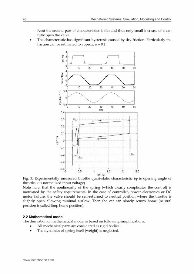
Next the second part of characteristics is flat and thus only small increase of u can fully open the valve.
The characteristic has significant hysteresis caused by dry friction. Particularly the friction can be estimated to approx. u = 0.1.
Fig. 3. Experimentally measured throttle quasi-static characteristic (φ is opening angle of throttle, u is normalized input voltage) Note here, that the nonlinearity of the spring (which clearly complicates the control) is motivated by the safety requirements. In the case of controller, power electronics or DC motor failure, the valve should be self-returned to neutral position where the throttle is slightly open allowing minimal airflow. Then the car can slowly return home (neutral position is called limp home position).
2.2 Mathematical model The derivation of mathematical model is based on following simplifications:
All mechanical parts are considered as rigid bodies. The dynamics of spring itself (weight) is neglected.
The inductance of brushed DC motor is neglected – the time constant of electrical circuit dynamics is much lower than mechanical.
The backlash in gearbox is neglected – even if there is obvious clearance, its significance is decreased in the working range of the valve due to the strong return spring.
Considering mentioned restrictions, the mechanical system has one degree of freedom and can be described using equation red e m k f ,J m b m m (1) where redJ is mechanical moment of inertia, em is electrical torque of DC motor, mb is mechanical viscous damping, km the torque of return spring and fm is dry friction torque. All variables are reduced to throttle angle φ (see Fig. 4). The transmission is characterized by
M 12
e M 12 12
im m i
(2)
where 12 is the efficiency.
Fig. 4. Schema of electromechanical throttle From the well-known brushed DC motor equation with neglected inductance (L=0) emf Mu Ri k (3) is formulated the current and the motor torque as a function of input voltage and angular velocity
emf 121 k ii uR R
(4)
2 2
emf 12 12 emf 12 12e .k i k im u
R R
(5)
Next, the eq. (1) can be rewritten as
www.intechopen.com

Modelling and Control of Electromechanical Servo System with High Nonlinearity 49
Next the second part of characteristics is flat and thus only small increase of u can fully open the valve.
The characteristic has significant hysteresis caused by dry friction. Particularly the friction can be estimated to approx. u = 0.1.
Fig. 3. Experimentally measured throttle quasi-static characteristic (φ is opening angle of throttle, u is normalized input voltage) Note here, that the nonlinearity of the spring (which clearly complicates the control) is motivated by the safety requirements. In the case of controller, power electronics or DC motor failure, the valve should be self-returned to neutral position where the throttle is slightly open allowing minimal airflow. Then the car can slowly return home (neutral position is called limp home position).
2.2 Mathematical model The derivation of mathematical model is based on following simplifications:
All mechanical parts are considered as rigid bodies. The dynamics of spring itself (weight) is neglected.
The inductance of brushed DC motor is neglected – the time constant of electrical circuit dynamics is much lower than mechanical.
The backlash in gearbox is neglected – even if there is obvious clearance, its significance is decreased in the working range of the valve due to the strong return spring.
Considering mentioned restrictions, the mechanical system has one degree of freedom and can be described using equation red e m k f ,J m b m m (1) where redJ is mechanical moment of inertia, em is electrical torque of DC motor, mb is mechanical viscous damping, km the torque of return spring and fm is dry friction torque. All variables are reduced to throttle angle φ (see Fig. 4). The transmission is characterized by
M 12
e M 12 12
im m i
(2)
where 12 is the efficiency.
Fig. 4. Schema of electromechanical throttle From the well-known brushed DC motor equation with neglected inductance (L=0) emf Mu Ri k (3) is formulated the current and the motor torque as a function of input voltage and angular velocity
emf 121 k ii uR R
(4)
2 2
emf 12 12 emf 12 12e .k i k im u
R R
(5)
Next, the eq. (1) can be rewritten as
www.intechopen.com

Mechatronic Systems, Simulation, Modelling and Control50
2 2
emf 12 12 emf 12 12red mech spring friction
k i k iJ u bR R
(6)
and normalized in voltage units k f ( ).J u b u u (7) Based on basic quasi-static experiment presented in Fig. 3, the nonlinear spring characteristic is shown in Fig. 5 and mathematically defined as
LH LH LHC S LHO
LHO OP LH S LHO
LHC CL LH S LHO
,,, .
S
k u u uu u k u u
u k u u
(8)
Further the friction Fu should be expressed. The friction modelling is nontrivial problem extensively studied by many researchers, good introduction to its application for control can be found in (Olsson, 1996). Basically, the friction models are: a) static; b) dynamic. The most simple and well-known static model is the Coulomb friction F kin( ) sgn( ) sgn( ) ,u N u (9) where N is normal force and is friction coefficient. This model is used for compensator design in Section 3.2 but is not suitable for modelling and parameter estimation.
Fig. 5. Schema of nonlinear return spring The dynamical friction models cover many aspects of observed real friction properties, such as increase of friction force in low velocities and presliding motion. In the field of servo system modelling and control, the LuGre model (Olsson, 1996) is the mostly often used. Similar properties has Reset Integrator model defined in the form:
0 00 if ( 0 ) ( 0 )otherwise
p p p pp
(10)
kinF
0
(1 ( ))( ) a p u pu pp
(11)
0if
( )0 otherwise.a p p
a p (12)
The model is defined by four parameters: kinu is the kinetic friction force, a defines the increase of friction in low velocity (stiction), is damping coefficient necessary for the numerical stability of the model and 0p determines the range of stiction. The p is new system dynamical state which can be understood as the bending or deformation of virtual bristles.
2.3 Offline parameter estimation Assume, that the complete nonlinear dynamical model of electromechanical throttle formed by equations (7), (8) and (10-12) is implemented in Simulink environment. Then the problem of parameter estimation consists of three main parts:
The generation of appropriate experimental input – output data sets. Generally, the input – output set is equal to physical one on real system, thus in the throttle case, the input would be the voltage u and output the valve opening angle φ. This approach is called estimation in open loop. However, it is very difficult to generate data in open loop and remain in angle limits (the throttle cannot be fully open because then the model is invalid). Therefore the estimation in close loop schematically shown in Fig. 6 has been used.
The searching for such model parameters, which minimizes the difference between experimental data and simulation model response. Technically, the estimation has been performed using Simulink PE tool with applied Nelder-Mead method.
Validation. The response of simulation model with estimated parameters is compared to experimental data sets which have not been used for estimation.
For the compensator design is mainly important the opening part of the throttle working range. The total number of parameters to be estimated is nine and estimated values are shown in Tab. 1.
www.intechopen.com

Modelling and Control of Electromechanical Servo System with High Nonlinearity 51
2 2
emf 12 12 emf 12 12red mech spring friction
k i k iJ u bR R
(6)
and normalized in voltage units k f ( ).J u b u u (7) Based on basic quasi-static experiment presented in Fig. 3, the nonlinear spring characteristic is shown in Fig. 5 and mathematically defined as
LH LH LHC S LHO
LHO OP LH S LHO
LHC CL LH S LHO
,,, .
S
k u u uu u k u u
u k u u
(8)
Further the friction Fu should be expressed. The friction modelling is nontrivial problem extensively studied by many researchers, good introduction to its application for control can be found in (Olsson, 1996). Basically, the friction models are: a) static; b) dynamic. The most simple and well-known static model is the Coulomb friction F kin( ) sgn( ) sgn( ) ,u N u (9) where N is normal force and is friction coefficient. This model is used for compensator design in Section 3.2 but is not suitable for modelling and parameter estimation.
Fig. 5. Schema of nonlinear return spring The dynamical friction models cover many aspects of observed real friction properties, such as increase of friction force in low velocities and presliding motion. In the field of servo system modelling and control, the LuGre model (Olsson, 1996) is the mostly often used. Similar properties has Reset Integrator model defined in the form:
0 00 if ( 0 ) ( 0 )otherwise
p p p pp
(10)
kinF
0
(1 ( ))( ) a p u pu pp
(11)
0if
( )0 otherwise.a p p
a p (12)
The model is defined by four parameters: kinu is the kinetic friction force, a defines the increase of friction in low velocity (stiction), is damping coefficient necessary for the numerical stability of the model and 0p determines the range of stiction. The p is new system dynamical state which can be understood as the bending or deformation of virtual bristles.
2.3 Offline parameter estimation Assume, that the complete nonlinear dynamical model of electromechanical throttle formed by equations (7), (8) and (10-12) is implemented in Simulink environment. Then the problem of parameter estimation consists of three main parts:
The generation of appropriate experimental input – output data sets. Generally, the input – output set is equal to physical one on real system, thus in the throttle case, the input would be the voltage u and output the valve opening angle φ. This approach is called estimation in open loop. However, it is very difficult to generate data in open loop and remain in angle limits (the throttle cannot be fully open because then the model is invalid). Therefore the estimation in close loop schematically shown in Fig. 6 has been used.
The searching for such model parameters, which minimizes the difference between experimental data and simulation model response. Technically, the estimation has been performed using Simulink PE tool with applied Nelder-Mead method.
Validation. The response of simulation model with estimated parameters is compared to experimental data sets which have not been used for estimation.
For the compensator design is mainly important the opening part of the throttle working range. The total number of parameters to be estimated is nine and estimated values are shown in Tab. 1.
www.intechopen.com

Mechatronic Systems, Simulation, Modelling and Control52
Parameter Estimated value
neutral (LH) position LH 0,45 voltage necessary for opening of the valve LHu 0,1330 slope of spring characteristic in opening range OPk 0,02079 electromechanical (viscous) damping b 0,025 inertial coefficient J 0,0004 friction parameters: kinetic friction Fkinu 0,06 static friction increase relatively to kinetic fr. a 0,330 friction damping coefficient 0,0100 stiction range coefficient 0p 0,0950
Tab. 1. Estimated parameters for opening range of throttle
Fig. 6. Block diagramm of data generation in closed loop for Parameter Estimation
3. Control of electromechanical servo with high nonlinearity
3.1 Rapid Control Prototyping hardware and software used for development The implementation of complex nonlinear controller is difficult and time consuming when target microcontroller and hand written C code is used. Instead, the Rapid Control Prototyping tool with following features has been used:
Based on Matlab/Simulink and dSPACE HW&SW. Direct generation of C code from Simulink to Power PC processor using Real-Time
Workshop and RT Interface. dSPACE modular HW consisting of main processor DS 1005 PPC, board DS 2103
with 14 bit D/A converters, board DS 2003 with 16 bit A/D converters, and communication cards DS 814 and 815.
The simulation model with middle complexity can be computed with 50μs rate, which is far beyond the requirements.
After successful development on RCP, the next step towards the realistic microcontroller for serial production can be made.
3.2 Design and implementation of model based controller There are three types of controller introduced in this section. Further the comparison of their performance is given.
PID – standard discrete implementation, used for comparison to other two improved controllers. For the computation of derivative action, the Tustin approximation or derivative impulse area invariant action (Pivonka & Schmidt, 2007) can be recommended.
s
d
s
d
1d
Ds 1
1( ) 11
GTT
GTT
T zu z eT
e z
(13)
Controller 1 – Feedback position error based compensator – the PID controller extended by feedforward spring compensation according eq. (8) and friction compensator which uses position error. The stability around the reference position can be increased by small dead zone d. The controller structure is schematically shown in Fig. 8.
PID spring frictionu u u u (14)
spring ref LH( )u f (15)
* *
friction F
, ifsign( ), , if
0, else
e d e du u e e e d e d
(16)
Fig. 7. Block diagram of Rapid Control Prototyping setup based on Matlab/Simulink software and dSPACE hardware and software
www.intechopen.com

Modelling and Control of Electromechanical Servo System with High Nonlinearity 53
Parameter Estimated value
neutral (LH) position LH 0,45 voltage necessary for opening of the valve LHu 0,1330 slope of spring characteristic in opening range OPk 0,02079 electromechanical (viscous) damping b 0,025 inertial coefficient J 0,0004 friction parameters: kinetic friction Fkinu 0,06 static friction increase relatively to kinetic fr. a 0,330 friction damping coefficient 0,0100 stiction range coefficient 0p 0,0950
Tab. 1. Estimated parameters for opening range of throttle
Fig. 6. Block diagramm of data generation in closed loop for Parameter Estimation
3. Control of electromechanical servo with high nonlinearity
3.1 Rapid Control Prototyping hardware and software used for development The implementation of complex nonlinear controller is difficult and time consuming when target microcontroller and hand written C code is used. Instead, the Rapid Control Prototyping tool with following features has been used:
Based on Matlab/Simulink and dSPACE HW&SW. Direct generation of C code from Simulink to Power PC processor using Real-Time
Workshop and RT Interface. dSPACE modular HW consisting of main processor DS 1005 PPC, board DS 2103
with 14 bit D/A converters, board DS 2003 with 16 bit A/D converters, and communication cards DS 814 and 815.
The simulation model with middle complexity can be computed with 50μs rate, which is far beyond the requirements.
After successful development on RCP, the next step towards the realistic microcontroller for serial production can be made.
3.2 Design and implementation of model based controller There are three types of controller introduced in this section. Further the comparison of their performance is given.
PID – standard discrete implementation, used for comparison to other two improved controllers. For the computation of derivative action, the Tustin approximation or derivative impulse area invariant action (Pivonka & Schmidt, 2007) can be recommended.
s
d
s
d
1d
Ds 1
1( ) 11
GTT
GTT
T zu z eT
e z
(13)
Controller 1 – Feedback position error based compensator – the PID controller extended by feedforward spring compensation according eq. (8) and friction compensator which uses position error. The stability around the reference position can be increased by small dead zone d. The controller structure is schematically shown in Fig. 8.
PID spring frictionu u u u (14)
spring ref LH( )u f (15)
* *
friction F
, ifsign( ), , if
0, else
e d e du u e e e d e d
(16)
Fig. 7. Block diagram of Rapid Control Prototyping setup based on Matlab/Simulink software and dSPACE hardware and software
www.intechopen.com

Mechatronic Systems, Simulation, Modelling and Control54
Controller 2 – Feedforward friction compensator – the PID controller extended by feedforward spring compensation and friction compensator which uses derivation (using eq. 13) of reference angle. Thus the compensator calculates friction using velocity. The controller structure is schematically shown in Fig. 9.
Fig. 8. Block diagram of PID controller extended by feedforward spring compensator and position error based friction compensator (Controller 1)
Fig. 9. Block diagram of PID controller extended by feedforward spring compensator and feedforward friction compensator (Controller 2)
3.3 Results Proposed controllers have been tested using two types of reference signal:
stairs reference – simulates sudden changes in required throttle position smooth reference – slowly and continuous changes.
Naturally, the selection of the control action sample time has crucial influence on performance. Two rates have been tested:
50μs – close to minimal sample time achieved by used RCP hardware, the maximal achievable performance is tested.
5ms – realistic sample time applicable in low cost microcontrollers used in final ECU.
The performance of three controllers described in the previous section with stairs/smooth reference signal and with 50us/5ms sample time is shown in Fig. 10, 11 and 12. In the case of stairs reference, the Controller 2 is not practicable.
Fig. 10. Comparison of controllers PID (left) vs. Controller 1 (right) performance with stairs reference angle, 50us sample time.
Fig. 11. Comparison of controllers PID (left) vs. Controller 1 (right) performance with stairs reference angle, 5ms sample time. For the stairs reference signal, Controller 1 gives very good results even at 5ms sample time. PID has very poor performance (Fig. 11). For the smooth reference signal, the control is different issue. PID can be used even at 5 ms, but the proportional gain must be higher compare to one applied to stairs ref. problem. All three controllers give comparable results of reference trajectory tracking, but differ
www.intechopen.com

Modelling and Control of Electromechanical Servo System with High Nonlinearity 55
Controller 2 – Feedforward friction compensator – the PID controller extended by feedforward spring compensation and friction compensator which uses derivation (using eq. 13) of reference angle. Thus the compensator calculates friction using velocity. The controller structure is schematically shown in Fig. 9.
Fig. 8. Block diagram of PID controller extended by feedforward spring compensator and position error based friction compensator (Controller 1)
Fig. 9. Block diagram of PID controller extended by feedforward spring compensator and feedforward friction compensator (Controller 2)
3.3 Results Proposed controllers have been tested using two types of reference signal:
stairs reference – simulates sudden changes in required throttle position smooth reference – slowly and continuous changes.
Naturally, the selection of the control action sample time has crucial influence on performance. Two rates have been tested:
50μs – close to minimal sample time achieved by used RCP hardware, the maximal achievable performance is tested.
5ms – realistic sample time applicable in low cost microcontrollers used in final ECU.
The performance of three controllers described in the previous section with stairs/smooth reference signal and with 50us/5ms sample time is shown in Fig. 10, 11 and 12. In the case of stairs reference, the Controller 2 is not practicable.
Fig. 10. Comparison of controllers PID (left) vs. Controller 1 (right) performance with stairs reference angle, 50us sample time.
Fig. 11. Comparison of controllers PID (left) vs. Controller 1 (right) performance with stairs reference angle, 5ms sample time. For the stairs reference signal, Controller 1 gives very good results even at 5ms sample time. PID has very poor performance (Fig. 11). For the smooth reference signal, the control is different issue. PID can be used even at 5 ms, but the proportional gain must be higher compare to one applied to stairs ref. problem. All three controllers give comparable results of reference trajectory tracking, but differ
www.intechopen.com

Mechatronic Systems, Simulation, Modelling and Control56
significantly in the oscillation of the control effort u. Although the good performance is achieved using PID, the high control activity (e.g. as in Fig. 12-left-a)) excites higher unmodelled dynamics causing hearable noise and possible wear of gears and all mechanical parts. Controller 1 and 2 have comparably lower control activity with the same tracking quality (Controller 2 is slightly better).
Fig. 12. Comparison of a) PID; b) Controller 1; c) Controller 2 performance for smooth reference signal. Left – sample time 50us, Right – sample time 5ms.
4. Conclusion
The control of servo mechanism with significant dry friction has been discussed in this chapter. The procedure of system structure identification, the modelling and parameter estimation is applicable generally to wide class of servos. The solution for particular actuator from automotive industry – so called electronic throttle – has been described in details. Beside the friction, the throttle has strongly nonlinear return spring which further complicates the control. Since the PID is not applicable for the system with dry friction nonlinearity, two nonlinear model-based controllers have been implemented and extensively tested with different types of reference and sample time. The controller with the friction compensation based on the feedback position error (Controller 1) proves very good performance for stairs reference while the feedforward velocity based friction compensation seems to be suitable for smooth reference. Both controllers have feedforward nonlinear spring compensator.
The throttle control as an example of X-by-wire concept allows achieving better fuel economy, lower emissions and the possibility to implement advanced traction control in the vehicle. Also, the nonlinear control described in this chapter illustrates the possibility of improving the poor mechanical system performance and thus leads to lower overall costs.
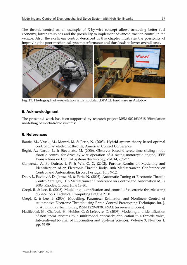
Fig. 13. Photograph of workstation with modular dSPACE hardware in Autobox 5. Acknowledgment
The presented work has been supported by research project MSM 0021630518 "Simulation modelling of mechatronic systems".
6. References
Baotic, M., Vasak, M., Morari, M. & Peric, N. (2003). Hybrid system theory based optimal control of an electronic throttle, American Control Conference
Beghi, A.; Nardo, L. & Stevanato, M. (2006). Observer-based discrete-time sliding mode throttle control for drive-by-wire operation of a racing motorcycle engine, IEEE Transactions on Control Systems Technology,Vol. 14, 767-775
Contreras, A. F., Quiroz, I. P. & Wit, C. C. (2002). Further Results on Modelling and Identification of an Electronic Throttle Body, 10th Mediterranean Conference on Control and Automation, Lisbon, Portugal, July 9-12.
Deur, J., Pavković, D., Jansz, M. & Perić, N. (2003). Automatic Tuning of Electronic Throttle Control Strategy, 11th Mediterranean Conference on Control and Automation MED 2003, Rhodes, Greece, June 18-20.
Grepl, R. & Lee, B. (2008). Modelling, identification and control of electronic throttle using dSpace tools. Technical Computing Prague 2008
Grepl, R. & Lee, B. (2009). Modelling, Parameter Estimation and Nonlinear Control of Automotive Electronic Throttle using Rapid Control Prototyping Technique, Int. J. of Automotive Technology, ISSN 1229-9138, KSAE (in review process).
Hadilebbal, M., Chafouk, H., Hoblos, G. & Lefebvre, D. (2007). Modeling and identification of non-linear systems by a multimodel approach: application to a throttle valve, International Journal of Information and Systems Sciences, Volume 3, Number 1, pp. 79-99
www.intechopen.com
Modelling and Control of Electromechanical Servo System with High Nonlinearity 57
significantly in the oscillation of the control effort u. Although the good performance is achieved using PID, the high control activity (e.g. as in Fig. 12-left-a)) excites higher unmodelled dynamics causing hearable noise and possible wear of gears and all mechanical parts. Controller 1 and 2 have comparably lower control activity with the same tracking quality (Controller 2 is slightly better).
Fig. 12. Comparison of a) PID; b) Controller 1; c) Controller 2 performance for smooth reference signal. Left – sample time 50us, Right – sample time 5ms.
4. Conclusion
The control of servo mechanism with significant dry friction has been discussed in this chapter. The procedure of system structure identification, the modelling and parameter estimation is applicable generally to wide class of servos. The solution for particular actuator from automotive industry – so called electronic throttle – has been described in details. Beside the friction, the throttle has strongly nonlinear return spring which further complicates the control. Since the PID is not applicable for the system with dry friction nonlinearity, two nonlinear model-based controllers have been implemented and extensively tested with different types of reference and sample time. The controller with the friction compensation based on the feedback position error (Controller 1) proves very good performance for stairs reference while the feedforward velocity based friction compensation seems to be suitable for smooth reference. Both controllers have feedforward nonlinear spring compensator.
The throttle control as an example of X-by-wire concept allows achieving better fuel economy, lower emissions and the possibility to implement advanced traction control in the vehicle. Also, the nonlinear control described in this chapter illustrates the possibility of improving the poor mechanical system performance and thus leads to lower overall costs.
Fig. 13. Photograph of workstation with modular dSPACE hardware in Autobox 5. Acknowledgment
The presented work has been supported by research project MSM 0021630518 "Simulation modelling of mechatronic systems".
6. References
Baotic, M., Vasak, M., Morari, M. & Peric, N. (2003). Hybrid system theory based optimal control of an electronic throttle, American Control Conference
Beghi, A.; Nardo, L. & Stevanato, M. (2006). Observer-based discrete-time sliding mode throttle control for drive-by-wire operation of a racing motorcycle engine, IEEE Transactions on Control Systems Technology,Vol. 14, 767-775
Contreras, A. F., Quiroz, I. P. & Wit, C. C. (2002). Further Results on Modelling and Identification of an Electronic Throttle Body, 10th Mediterranean Conference on Control and Automation, Lisbon, Portugal, July 9-12.
Deur, J., Pavković, D., Jansz, M. & Perić, N. (2003). Automatic Tuning of Electronic Throttle Control Strategy, 11th Mediterranean Conference on Control and Automation MED 2003, Rhodes, Greece, June 18-20.
Grepl, R. & Lee, B. (2008). Modelling, identification and control of electronic throttle using dSpace tools. Technical Computing Prague 2008
Grepl, R. & Lee, B. (2009). Modelling, Parameter Estimation and Nonlinear Control of Automotive Electronic Throttle using Rapid Control Prototyping Technique, Int. J. of Automotive Technology, ISSN 1229-9138, KSAE (in review process).
Hadilebbal, M., Chafouk, H., Hoblos, G. & Lefebvre, D. (2007). Modeling and identification of non-linear systems by a multimodel approach: application to a throttle valve, International Journal of Information and Systems Sciences, Volume 3, Number 1, pp. 79-99
www.intechopen.com

Mechatronic Systems, Simulation, Modelling and Control58
Isermann, R. (1996). Information processing for mechatronic systems, Robotics and Autonomous Systems, 16, 117-134
Isermann, R.; Lachmann, K. & Matko, D. (1991). Adaptive Control Systems, Prentice Hall Ishikawa, M.; McCune, D.; Saikalis, G. & Oho, S. (2007). CPU Model-based
Hardware/Software Co-design, Co-simulation and Analysis Technology for Real-Time Embedded Control Systems, 13th IEEE Real Time and Embedded Technology and Applications Symposium
Jung, H.; Kwak, B. & Park, Y. (2000). Slip Controller Design for Traction Control System International Journal of Automotive Technology,Vol. 1, 48-55
Olsson, H. et al. (1998). Friction models and friction compensation. Eur. J. Control 4(3):176-195.
Pavković, D.,Deur, J., Jansz, M. & Perić, N. (2006). Adaptive Control of Automotive Electronic Throttle, Control Engineering Practice, 14, pp. 121 – 136.
Pivonka, P. & Schmidt, M. (2007). Comparative Analysis of Discrete Derivative Implementations in PID Controllers. Systems Theory and Applications, vol.2. WSEAS, ISBN: 978-960-8457-90-4, pp. 33-37
Ryu, J.; Yoon, M. & Sunwoo, M. (2005). Development Of a Network-Based Traction Control System, Validation Of Its Traction Control Algorithmand Evaluation Of Its Performance Using Net-Hils, International Journal of Automotive Technology, Vol. 6, No. 2, pp. 171−181
Stence, R. W. (2006). Digital By-Wire Replaces Mechanical Systems in Cars, in Electronic Braking, Traction, and Stability Controls, Society of Automotive Engineers, Inc., USA, pp. 29-36
Trebi-Ollennu, A. & Dolan, J. M. (2004). Adaptive Fuzzy Throttle control for an All Terrain Vehicle, Institute for Complex Engineered Systems, Carnegie Mellon University, Internal Report 04"
Young, K. D.; Utkin, V. I. & Ozguner, U. (1999). A Control Engineer’s Guide to Sliding Mode Control IEEE Transactions on Control Systems Technology, Vol. 7
Vašak, M., Baotić, M., Petrović, I. & Perić, N. (2007). Hybrid Theory-Based Time-Optimal Control of an Electronic Throttle, IEEE Transactions on Industrial Electronics, 54, pp. 1483-1494.
Yang, C. (2004). Model-Based Analysis and Tuning of Electronic Throttle Controllers, SAE World Congress, Detroit, Michigan, March 8-11
Zhang, P., Yin, Ch.,& Zhang, J. (2006). Sliding Mode Control with Sensor Fault Tolerant for Electronic Throttle, International Conference on Automation Science and Engineering, Shanghai, China
www.intechopen.com

Mechatronic Systems Simulation Modeling and ControlEdited by Annalisa Milella Donato Di Paola and Grazia Cicirelli
ISBN 978-953-307-041-4Hard cover, 298 pagesPublisher InTechPublished online 01, March, 2010Published in print edition March, 2010
InTech EuropeUniversity Campus STeP Ri
InTech ChinaUnit 405, Office Block, Hotel Equatorial Shanghai
This book collects fifteen relevant papers in the field of mechatronic systems. Mechatronics, the synergisticblend of mechanics, electronics, and computer science, integrates the best design practices with the mostadvanced technologies to realize high-quality products, guaranteeing at the same time a substantial reductionin development time and cost. Topics covered in this book include simulation, modelling and control ofelectromechanical machines, machine components, and mechatronic vehicles. New software tools, integrateddevelopment environments, and systematic design methods are also introduced. The editors are extremelygrateful to all the authors for their valuable contributions. The book begins with eight chapters related tomodelling and control of electromechanical machines and machine components. Chapter 9 presents anonlinear model for the control of a three-DOF helicopter. A helicopter model and a control method of themodel are also presented and validated experimentally in Chapter 10. Chapter 11 introduces a planarlaboratory testbed for the simulation of autonomous proximity manoeuvres of a uniquely control actuatorconfigured spacecraft. Integrated methods of simulation and Real-Time control aiming at improving theefficiency of an iterative design process of control systems are presented in Chapter 12. Reliability analysismethods for an embedded Open Source Software (OSS) are discussed in Chapter 13. A new specificationtechnique for the conceptual design of self-optimizing mechatronic systems is presented in Chapter 14.Chapter 15 provides a general overview of design specificities including mechanical and control considerationsfor micro-mechatronic structures. It also presents an example of a new optimal synthesis method to designtopology and associated robust control methodologies for monolithic compliant microstructures.
How to referenceIn order to correctly reference this scholarly work, feel free to copy and paste the following:
Grepl R. (2010). Modelling and Control of Electromechanical Servo System with High Nonlinearity,Mechatronic Systems Simulation Modeling and Control, Annalisa Milella Donato Di Paola and Grazia Cicirelli(Ed.), ISBN: 978-953-307-041-4, InTech, Available from: http://www.intechopen.com/books/mechatronic-systems-simulation-modeling-and-control/modelling-and-control-of-electromechanical-servo-system-with-high-nonlinearity
www.intechopen.com

Slavka Krautzeka 83/A 51000 Rijeka, Croatia Phone: +385 (51) 770 447 Fax: +385 (51) 686 166www.intechopen.com
No.65, Yan An Road (West), Shanghai, 200040, China
Phone: +86-21-62489820 Fax: +86-21-62489821