grid connected photovoltaic systems: challenges … connected photovoltaic systems: challenges and...
TRANSCRIPT
Grid Connected Photovoltaic Systems:
Challenges and Control Solutions - A Potential
Review
Sivasankari Sundaram, K. N. Sheeba, and Jakka Sarat Chandra Babu National Institute of Technology, Tiruchirappalli, India
Email: [email protected], {sheeba, sarat}@nitt.edu
Abstract—The thirst for energy has brought out the
existence of grid connected solar photovoltaic systems to
meet out the reduction in the energy bill, which act as a cost
saving methodology with simultaneous gain of incentives
from the government for transporting the power to the
national grid. Hence the operational objectives and the
control strategies employed for its efficient operation are to
be well studied. This paper thus discusses in detail about its
topology, grid standards, real time challenges and objectives
incorporating even the ancillary control schemes. A review
is made on the control techniques which are made available
for the DC (PV side) and AC side (grid side). A comparative
analysis is made on each of the techniques based on the
response parameters concluding the suggestion of most
appropriate strategy for tolerable operation of grid
connected photovoltaic systems.
Index Terms—grid connected photovoltaic system, MPPT
control, current control, phase synchronization and direct
power control
I. INTRODUCTION
The installation of Solar systems in India had risen
from 35.15MW in 2011 to 941.25MW in 2012 and India
aims at achieving 20GW solar power installations by
2020 and also to achieve grid parity by 2020 [1]. India is
likely to install additional capacity of 1300MW to
1400MW of solar powered plants in 2013-2014. Thus it
is clearly inferred from the figures above that the usage of
solar energy is on rise. Solar photovoltaic systems are
broadly classified into stand alone PV systems and grid
connected PV systems. Solar PV serves as a sole source
of energy satisfying the load demand in stand-alone
systems where as in grid connected PV systems, the main
AC grid also supports the occurring load demand. The
total installed capacity of grid interactive renewable
power (inclusion of all sources), which was
19,971.03MW as in 2011 had gone up to 24,914.24MW
in 2012 indicating a growth of 24.75%. The installed grid
connected solar power is 1035MW and the cumulative
capacity of off-grid solar PV is 85MW as in October
2012 [2]. Hence the installation of grid connected
photovoltaic systems goes on rise in comparison to stand
alone systems.
Manuscript received July 16, 2015; revised March 24, 2016.
The rise is also due to the Government’s support and
attractive incentives to the installation of PV systems. A
great deal of research has been done on the grid
connected PV system. Thus, it becomes essential to know
the control techniques employed in grid connected solar
PV systems. As solar PV systems integrate both the direct
current mode and the alternating current mode, the
control of both the DC side or the PV side and the grid
side or the inverter side comes into picture. Out of the
above two controls the AC side control poses more
complexity and is harder to implement. This article will
be helpful for budding researchers with the projection of
technical challenges and solution for grid connected PV
systems.
II. STRUCTURE OF GRID CONNECTED PV SYSTEM
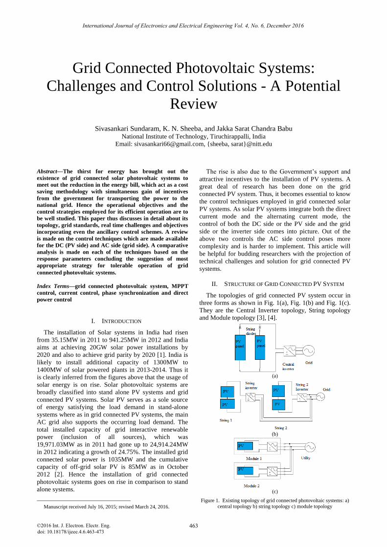
The topologies of grid connected PV system occur in
three forms as shown in Fig. 1(a), Fig. 1(b) and Fig. 1(c).
They are the Central Inverter topology, String topology
and Module topology [3], [4].
(a)
(b)
(c)
Figure 1. Existing topology of grid connected photovoltaic systems: a) central topology b) string topology c) module topology
International Journal of Electronics and Electrical Engineering Vol. 4, No. 6, December 2016
©2016 Int. J. Electron. Electr. Eng. 463doi: 10.18178/ijeee.4.6.463-473
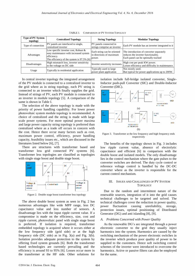
TABLE I. COMPARISON OF PV SYSTEM TOPOLOGY
Type of PV System
topology Centralized Topology String Topology Modular Topology
Type of connection PV panels are interfaced to single,
centralized inverter
PV panels connected in
strings comprise an inverter Each PV module has an inverter integrated to it
Advantages
Low specific inverter cost, Robust & easy maintenance with increased system
efficiency.
The efficiency of the system is 97.5% [6]
Each string can be oriented
in directions of maximum power.
The introduction of converter separately
reduces the inverter functionality. Each panel can be optimally tracked
Disadvantages High mismatch loss, inverter sensitivity to the voltage on DC side
Inverter sensitivity increases. High cost per peak KW power. Lower efficiency and difficulty in maintenance.
Usage Typically in residential application Typically used in large
power plant application
Not mostly used.
But typical for power applications up to 200W.
In central inverter topology the integrated arrangement
of the PV module is connected to a centralized inverter to
the grid where as in string topology, each PV string is
connected to an inverter which finally supplies the grid.
Instead of strings of PV, each PV module is connected to
an inverter in module topology [5]. A comparison of the
same is shown in Table I.
The selection of the above topology is made with the
priority of power handling capability. For lower power
photovoltaic system module topology is recommended. A
choice of centralized and the string is made with large
scale power systems. For more optimal power maxima
and large power capacity string topology is preferred than
centralized where as a trade off occurs in concern with
the cost. Hence there occur many factors such as cost,
maximum power control, efficiency, power handling
capacity, feasibility issues etc., which are discussed in the
literatures listed below [6], [7].
There are structures with transformer based and
transformer less grid connected PV systems [6].
Transformer less topologies are classified as topologies
with single stage boost and double stage boost.
Figure 2. Double stage boost transformer less topology
The above double boost system as seen in Fig. 2 has
numerous advantages like wide MPP range, less DC
capacitance value and less number of sensors. A
disadvantage lies with the input ripple current value. If a
compromise is made on the efficiency, size, cost and
ripple current, photovoltaic panel with single stage boost
is preferred. If isolation is required, transformer
embedded topology is acquired where it occurs either at
the low frequency side (grid side) or at the high
frequency side (DC side) as in Fig. 3(a) and Fig. 3(b).
Isolation provides adequate protection to the system by
offering fixed system grounds [6]. Both the transformer
based technologies are currently prevailing and the
efficiency is around 93 to 95% [6]. Losses occur more in
the transformer at the HF side. Other solutions for
isolation include full-bridge isolated converter, Single-
Inductor push-pull Converter (SIC) and Double-Inductor
Converter (DIC).
(a)
(b)
Figure 3. Transformer at the low frequency and high frequency ends
respectively
The benefits of the topology shown in Fig. 3 includes
low ripple current value, absence of electrolytic
capacitance and efficient [6] in comparison with the
double boost and isolated models. The only disadvantage
lies in the control mechanism where the gate pulses to the
converter switches are derived. The duty cycle control or
reference voltage control is handled by the DC-DC
converter where as the inverter is responsible for the
current control mechanism.
III. ISSUES AND CHALLENGES OF PV SYSTEM
TOPOLOGY
Due to the random and intermittent nature of the
renewable sources, integration of it into the grid causes
technical challenges to be targeted and solved. The
technical challenges cover the reduction in power quality,
power fluctuation causing unreliability, storage,
protection issues, optimal positioning of Distributed
Generator (DG) and anti islanding [8], [9].
A. Problems Concerned with Power Quality
As the renewable DG’s are integrated through a power
electronic converter to the grid they usually inject
harmonics into the system. Harmonics are caused by the
switching mechanism of the power electronic switches in
the inverter which produce poor quality of power to be
supplied to the customers. Hence soft switching control
schemes of the inverter were introduced to overcome the
harmonics. Active or passive filters can also be employed
for the same.
International Journal of Electronics and Electrical Engineering Vol. 4, No. 6, December 2016
©2016 Int. J. Electron. Electr. Eng. 464

Change in the frequency and the operating voltage can
also occur due to the varying nature of the DG which
affects the power flow [8]. The disconnection and
reconnection of renewable energy source to the grid
depending on the load demand causes voltage flicker.
Appropriate tap settings for the transformer connecting
the feeder to the grid should be made, which is more
useful when two or more feeders are supplied by the
same transformer, but the DG is concentrated on only one
of the above feeder [10]. In addition, digital voltage
control algorithms evolve [9] to solve the problem.
Unbalanced voltage profile arises due to the
interconnection of single phase source with the three
phase load or vice-versa. Unbalanced voltage will further
lead to unbalanced current which deduces the quality of
the system [11], [12].
B. Storage
Due to the incorporation of renewable or PV source in
the grid power path flow, the standard of the grid comes
down. The grid may act as a source or sink of power in
accordance to the power generated from the distributed
generator (PV). If the PV power generation is surplus or
in case of a weak grid, battery can be made as a choice of
storing the excess power [8]. But introducing a battery to
the grid connected PV systems invites issues of sizing
and battery current and voltage control.
C. Protection Issues
Traditional power systems are protected by over-
current/overvoltage relays and circuit breakers. But as
energy conversion systems (solar) are introduced the
protection of the network becomes more complex. The
issues of alteration in the short circuit level, lack of
sustained fault current and reverse power flow persists.
D. Short Circuit Level Change
The short circuit level is an important design parameter
in the design of protective devices such as circuit
breakers and relays. This is usually characterized by the
equivalent system impedance [8] at the fault point and
indicates the amount of fault current for the relay to act
upon the fault. The equivalent impedance does not vary
with the grid powered network systems, but varies with
the DG network systems as the input changes to it
changes instantaneously. Since the SCC varies the
forecast of the fault current magnitude changes which
cannot be withstood by the designed circuit breaker rating
right through the operation.
E. Reverse Power Flow
Conventional power systems possess unidirectional
power flow. But as a renewable energy source is
integrated to the conventional power system the power
flow reversal takes place which alters the operation of
protection circuits [8].
F. Lack of Sustained Fault Current
For the protection of the system from the fault current
switch gear and circuit breakers are installed, which
differentiates the fault current from the normal current.
This differentiation is made with the significant increase
in the fault current than the normal current. If the
magnitude of the fault current varies from the DG then
there is a tough task for the circuit breaker to identify the
fault current amidst the normal current. Solar systems
mainly employ power electronic switches which do not
supply sustained fault currents [8].
G. Islanding
Islanding is a unique problem of the grid connected PV
system. Islanding occurs on grid failure. Auto reclosure
valve at the point of common coupling of the renewable
generator to the grid is kept open offering the separation
of the utility network with the grid. Else the voltage
builds up on power generation without the energy
absorption by the grid causing huge voltage unbalance
resulting in system deterioration. Thus the anti islanding
control technique came into picture [8], [11] for
addressing the above problem. The standard anti
islanding control techniques include over-voltage relay,
under-voltage relay, over-frequency and under frequency
relays. In addition to the standard schemes active and
passive schemes are introduced for reducing the
probability of islanding. Voltage harmonic monitoring,
phase jump detection and slide mode frequency shift,
branch out from passive schemes whereas Impedance
measurement and active frequency drift come under the
active scheme.
IV. GRID INTERCONNECTION STANDARDS
As the issues with the grid standards go on high, the
design of the grid connected PV is subjected to follow
grid standards which vary with the location of the grid
over the globe. Some of the most important standards are
the International Electro technical commission standards
and Institute of Electrical Engineering standards. More
specifically, IEEE standard 1547-2003 is employed for
interconnecting distributed sources with power systems
[13] and IEC61727 [14] second edition 2004-2012 for PV
system interaction with the utility. Voltage, DC injection,
flicker, frequency distribution or harmonics and power
factor limits for tolerable operation of 10 to 30KW grid
connected PV system as shown in the Table II below.
TABLE II. GRID STANDARDS
Performance
Parameters IEC61727 IEEE1547
Nominal Power 10kW 30KW
Maximum current THD 5.0% 5.0%
Harmonic current
(3-9) 4.0% (11-15) 2.0%
(17-21) 1.5%
(23-33) 0.6%
(2-10) 4.0%
(11-16) 2.0%
(17-22) 1.5% (23-34) 0.6%, (>35)
0.3%.
Power factor at 50% of
rated power 0.90 -
DC current injection
Less than 1.0%
of rated output
current
Less than 0.5% of rated output current
Voltage range 85%-110 % 88%-110%
Frequency range for normal operation
50±1Hz 59.3Hz to 60.5Hz
International Journal of Electronics and Electrical Engineering Vol. 4, No. 6, December 2016
©2016 Int. J. Electron. Electr. Eng. 465
V. CONTROL OBJECTIVES OF GRID CONNECTED PV
SYSTEM
The control objectives of grid connected system are
partitioned mainly into DC side control and AC side
control represented in Fig. 4. The common functions of
GPV include DC voltage control [15] adapting input
voltage variations, grid synchronization for unity power
factor control and grid current control for system stability
[15].
Figure 4. Existing control objectives of grid connected PV system
The specific application of grid connected PV system
includes the maximum power point tracking control, Anti
islanding as per IEEE1574 standards, unity power factor
operation, fault current control harmonic control and
voltage fluctuation control thereby maintaining the power
quality standards. Other ancillary applications include sun
tracking, plant monitoring and active or reactive power
control.
A. Specific DC Side Function
1) MPPT control
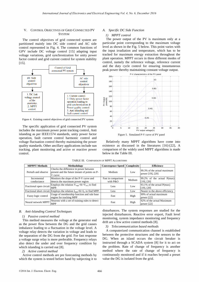
The power output of the PV is maximum only at a
particular point corresponding to the maximum voltage
level as shown in the Fig. 5 below. This point varies with
the input irradiation and temperature, which has to be
tracked for maximum energy extraction throughout the
plant operation. MPPT occurs in three different modes of
control, namely the reference voltage, reference current
and the duty cycle control for ensuring instantaneous
peak power thereby maintaining constant voltage output.
0 5 10 15 20 25 30 35 400
20
40
60
80
100
120
140
160
180
200
0.2G
0.4G
0.6G
0.8G
1G
PV
Outp
ut
pow
er(
W)
PV output voltage(V)
P-V characteristics of the PV panel
Figure 5. Simulated P-V curve of PV panel
Relatively many MPPT algorithms have come into
existence as discussed in the literatures [16]-[22]. A
comparison of the widely used MPPT algorithms is made
below in the Table III.
TABLE III. COMPARISON OF MPPT ALGORITHMS
MPPPT Methods Methodology Convergence Speed Complexity Efficiency
Perturb and observe
Checks the difference in power between
present and the future instant of points on P-V curve
Medium Low 99.3% of the actual maximum power [19], [20]
Incremental
conductance
Monitors the slope of the P-V curve and
detects the maximum power region
Fast in comparison
with P&O Medium
99.2% of the actual P(max)
[19], [20]
Fractional open circuit Employs the relation Vmpp=K×V(oc) to find MPP.
Less Low 93.1% of the actual P(max) [19], [20]
Fractional short circuit Employs the relation Impp=K×Isc to find MPP. Less Low Nearer to the above efficiency
Fuzzy logic control Usage of membership function and rule base engine for tracking MPP
Fast High 99% of actual maximum power [22]
Neural network MPPT Neurons with a set of training rules to detect
MPP Fast High
92% of the actual Maximum
power [22]
B. Anti-Islanding Control Techniques
1) Passive control method
This method measures the voltage at the generator end
as the power flow between the DG and the grid causes
imbalance leading to a fluctuation in the voltage level. A
voltage relay detects the variation in voltage and leads to
the separation of the DG from the grid. For fast response
a voltage surge relay is more preferable. Frequency relays
also detect the under and over frequency condition by
which islanding is carried out [8].
2) Active control method
Active control methods are pre forecasting methods by
which the system is tested before hand by subjecting it to
disturbances. The system responses are studied for the
injected disturbances. Reactive error export, Fault level
monitoring, system impedance monitoring and frequency
drift are a few active control methods [8].
3) Telecommunication based methods
A computerized communication channel is established
between the protective structures and the sensors to the
DG. When an island occurs the circuit breaker is
instructed through a SCADA system [8] for it to act on
the problem. Rate of change of frequency is another
method where the rate of change of frequency is
continuously monitored and if it reaches beyond a preset
value the DG is isolated from the grid.
International Journal of Electronics and Electrical Engineering Vol. 4, No. 6, December 2016
©2016 Int. J. Electron. Electr. Eng. 466
VI. GRID CONTROL TECHNIQUES
The grid control techniques form the essential and the
complex function for the standardized operation of the
grid connected PV system as described in Fig. 6. These
techniques focus on the methodologies for the generation
of PWM pulses to the converter or inverter switches
which offers sinusoidal grid current injection to the
system. This section encloses in detail about the control
techniques reviewed in the literatures [23]-[29] with a
comparison of it making a brief conclusion.
Figure 6. Classification of grid control techniques
A. Current Control Techniques in Grid Connected PV
System
The current control is responsible for the stability of
the grid current. The design of the controller for
comparison of grid reference current with the actual
brings the evolution of linear and non-linear current
control technique. They are further subdivided into
strategies such as PI current control, PR resonant current
control, dq frame current control, dq frame current
control with feed forward harmonic compensation [30]-
[41]. The non –linear techniques include the Hysteresis
current control, predictive current control or dead beat
control, sliding mode control [42]-[48]. Direct power
control forms the ancillary control part [49]-[51].
1) PI current control
A typical PI current control is shown in Fig. 7. The P
controller’s steady state error is eliminated by adding an
integral component to the transfer function [24]. The
reference current is obtained from the grid voltage on
employing a gain. The measured output inverter current is
compared with the above reference and the error is
controlled by a PI current controller. The integral part of
the PI compensator minimizes errors at low frequency,
while proportional gain is related to the amount of ripple
or reduces the transient response. The PWM signal is
finally obtained from the processed control signal in the
PWM generator block in comparison with constant
frequency triangular signals of fixed switching frequency
[30]-[32]. As the output grid voltage should be in phase
with the output current, the reference current was
obtained from the grid voltage leading to unity power
factor operation. The maximum slope of error signals
should never exceed the triangular slope of the carrier
signals. Additional problems may arise from multiple
crossing of triangular boundaries. The advantage of the PI
control includes the reduction in the steady state error and
less effect of DC-side ripple on the inverter load side
waveforms.
Figure 7. PI current control flow diagram
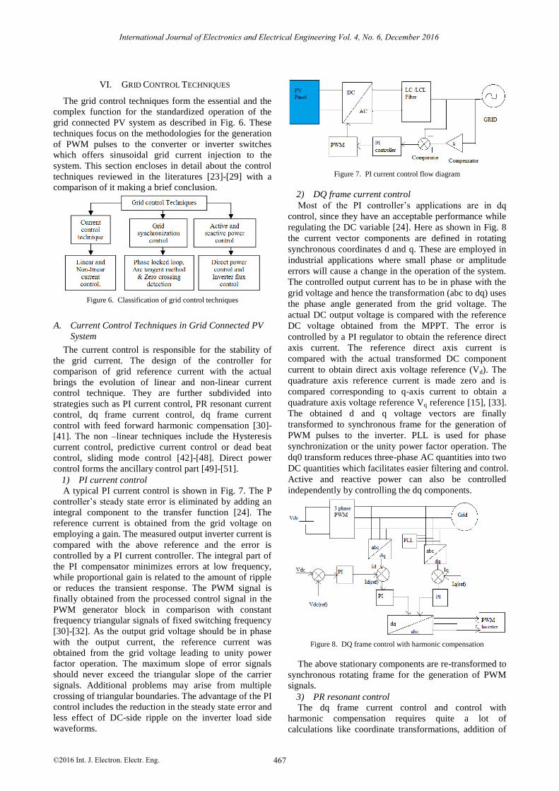
2) DQ frame current control
Most of the PI controller’s applications are in dq
control, since they have an acceptable performance while
regulating the DC variable [24]. Here as shown in Fig. 8
the current vector components are defined in rotating
synchronous coordinates d and q. These are employed in
industrial applications where small phase or amplitude
errors will cause a change in the operation of the system.
The controlled output current has to be in phase with the
grid voltage and hence the transformation (abc to dq) uses
the phase angle generated from the grid voltage. The
actual DC output voltage is compared with the reference
DC voltage obtained from the MPPT. The error is
controlled by a PI regulator to obtain the reference direct
axis current. The reference direct axis current is
compared with the actual transformed DC component
current to obtain direct axis voltage reference (Vd). The
quadrature axis reference current is made zero and is
compared corresponding to q-axis current to obtain a
quadrature axis voltage reference Vq reference [15], [33].
The obtained d and q voltage vectors are finally
transformed to synchronous frame for the generation of
PWM pulses to the inverter. PLL is used for phase
synchronization or the unity power factor operation. The
dq0 transform reduces three-phase AC quantities into two
DC quantities which facilitates easier filtering and control.
Active and reactive power can also be controlled
independently by controlling the dq components.
Figure 8. DQ frame control with harmonic compensation
The above stationary components are re-transformed to
synchronous rotating frame for the generation of PWM
signals.
3) PR resonant control
The dq frame current control and control with
harmonic compensation requires quite a lot of
calculations like coordinate transformations, addition of
International Journal of Electronics and Electrical Engineering Vol. 4, No. 6, December 2016
©2016 Int. J. Electron. Electr. Eng. 467

harmonic compensator which sub includes cross
couplings of d and q axis for improved dynamic response.
But in PR resonant control the transformations are
reduced and cross coupling is removed, which makes the
implementation of the control technique simpler.
Moreover PR controller achieves very high gain in a
narrow frequency band centered around the resonant
frequency [35]-[39].
The transfer function of the PR resonant control is
given by:
G(s)= * /( ^ 2 ^ 2)p ik k s s (1)
where Kp and Ki are the proportional and the integral
control gains. ω corresponds to the resonant frequency.
The width of the frequency band about the resonance
point depends on the integral time constant of Ki.
Harmonic compensation as in the dq current control
can also be achieved by PR control. A typical Harmonic
Compensator (HC) can be introduced for compensation
of selective harmonics like the third, fifth, and seventh
harmonics and its corresponding transfer function is
shown below.
3,5,7
( ) * ( /( ^ 2 ( ) ^ 2))ih
h
Gh s K s s h
(2)
where ω is the natural resonance frequency, h is the
harmonic number and Kih is the integral gain of the
related harmonic. A comparison of current control
schemes are tabulated in Table IV and Table V.
Control
Techniques High gain
Steady state
error
Elimination
Dynamic
response
Harmonic
Compensation
PI control At lower
frequencies Good Fast Poor
PR control Around resonant
frequencies
Very good Rapid Poor
DQ control with harmonic
compensation
High gain at
integral multiples of
fundamental
frequency
Very good Slow Good
TABLE V. COMPARISON OF LINEAR CURRENT CONTROL TECHNIQUES
Linear current
control techniques Current THD Advantages Disadvantages
PI Current control 8% of the peak rms current value
[31]
1. Devoid of transformations which increases complexity
2. Less effect of DC side ripple on
the inverter
1. Multiple triangular signal crossing
occurs on the generation of PWM. 2. Difficulty in removing the steady-state
error in a stationary reference frame.
3. Less robust.
Dq frame current control
3.5% [41]
1. Accurate control on grid
imbalances can be achieved.
2. Elimination of steady state error
1. System complexity increases as synchronous transformations are involved.
PR current control 1.46% [37]
1. More robust and high gain.
2. Capability of eliminating steady-
state error when regulating sinusoidal signals
1. Complex but not as complex DQ control
DQ frame control
with harmonic compensation
Not accurately available. But Lesser
than above methods as harmonic compensator is involved.
1. Harmonic compensation is done
by adding the respective harmonic order to the PI controller
2. Enhances system stability
1. Complexity arises by adding harmonic compensator.
4) Discussion and conclusion of linear control
techniques
PI current control is typically a simple control offering
the objective of phase synchronization among grid
voltage and grid current with less concentration over the
THD limits. Steady state error elimination is also poor in
comparison with the other linear methods. Thus, if a cost
effective or complexity selection line occurs PI current
control is more preferable. If the dynamic response of the
controller is not the most important aspect to be
considered then PR controllers are employed. Dynamic
response varies with the solar input conditions. Though
PR Resonant control offers more robust operation than
the PI control, DQ control with harmonic compensation
can always be recommended as the system remains stable
even to disturbances in spite of the complexity in
transformation.
B. Non-Linear Current Control Techniques
1) Hysteresis current controller
Figure 9. Hysteresis current controller applied to grid connected PV systems
The hysteresis control limits the control range to the
hysteresis band which is set by the error in the reference
current and the measured output current [42], [43] as seen
in Fig. 9. The lowest error is set by the lower limit of the
hysteresis band and the highest error is set by the upper
limit of the hysteresis band. As the current increases and
crosses the upper hysteresis limit, the lower device is
turned on. As the current falls and crosses the lower band
the upper device is turned on. The advantages of
International Journal of Electronics and Electrical Engineering Vol. 4, No. 6, December 2016
©2016 Int. J. Electron. Electr. Eng. 468
TABLE IV. COMPARISON OF CONTROL STRATEGIES WITH UNIQUE
FEATURES

hysteresis control are its simplicity, robustness, lack of
tracking errors, independence of load parameter changes,
and extremely good dynamics limited only by switching
speed and load time constant [42]. Though, it has some
disadvantages which are the variation in converter
switching frequency with the output inverter voltage and
rough operation due to the inherent randomness caused
by the limit cycle or the hysteresis band, protection of the
converter becomes difficult.
2) Constant switching frequency operation of
hysteresis current controller
The tolerance band or the hysteresis band amplitude
can be varied according to the AC-side voltage or by
means of a PLL control. The other way of maintaining
the switching frequency is to decouple the error signals
by subtracting an interference signal derived from the
mean inverter voltage [29] as shown in the Fig. 10 below.
Figure 10. Decoupled, constant average switching frequency hysteresis
controller [29]
3) Current regulated delta controller
The current regulated delta controller is same as the
hysteresis controller with a latching device [25] attached
to it represented in Fig. 11. The advantage of this control
is to control the switching frequency to our desirable
frequency by enabling the latch with a clock signal. The
reference three phase grid currents are compared with the
actual currents resulting in an error signal which is further
given as input to the comparator. The comparator acts as
a hysteresis band limiter limiting the current between the
upper and the lower band limits. The pulses thus
generated are given to the latching circuit as binary
values. The value 1 indicates the latch is enabled for
PWM generation. The clock signal is also responsible for
the inverter to track the reference current with the actual
currents effectively.
Figure 11. Current delta regulated control methodology
The harmonic compensation is held effectively without
inclusion of a separate harmonic compensator.
4) Modified ramp type controller
The ramp controller described in Fig. 12 involves the
comparison of the triangular signals of fixed amplitude
and frequency with the error signals derived from the
current controller. The triangular signals act as a carrier
wave with error signals modulating it. Constant switching
frequency is achieved as triangular signals with fixed
frequency are employed. The disadvantage of this control
is that the output current has amplitude and phase errors.
In order to overcome the disadvantage phase shifters are
included where the triangular wave of constant amplitude
are phase shifted by 120° [25]. The schematic is shown
below.
Figure 12. Modified ramp type controller methodology
5) Deadbeat/Predictive control
Dead beat predictive time control employs a discrete-
time model which is able to predict the current in the
future (time k+1) based on actual or present
measurements (at time k) and the converter voltage to be
applied. These predicted values will be used as inputs for
a cost function block and the voltage vector producing the
lowest value of the cost function is selected to be applied
during the next sampling instant [44]-[46]. This kind of
controller though well known for their inclusion of
nonlinearities of the system, high precision of current
control and fastest transient response causes
computational complexity leading to large control loop
time period and sensitivity changes to plant uncertainties.
When the choice of the voltage vector is made in order to
nullify the error at the end of each cycle, the predictive
regulation is rightly called “dead beat control”. The dead
beat control topology is adopted as shown in Fig. 13.
The future value of load current is given by:
( 1) ( ( ) / )*( ( ) ( )) ( )(1 * ( ) / )I k T s L V k e k I k R T s L (3)
where V(k) and I(k) is the measured grid current the
future value of reference current is determined by using
Lagrange quadratic extrapolation.
( 1) 3 ( ) 3 ( 1) ( 2)I * k I k I * k I * k (4)
Figure 13. Deadbeat/Predictive current control algorithm
6) Sliding mode control
Sliding mode control shown in Fig. 14 is a non-linear
control or a system motion control which is robust in the
presence of parameter uncertainties and disturbances. It is
more suitable for time varying systems. It has the ability
to regulate the system to follow the trajectories defined
by the sliding surface which is mostly similar to the
International Journal of Electronics and Electrical Engineering Vol. 4, No. 6, December 2016
©2016 Int. J. Electron. Electr. Eng. 469

hysteresis band in the hysteresis current control. The
equilibrium state is constructed so that the system is
restricted to a desired manifold and has a desired
behavior. The three steps which involve the design of the
sliding mode controller is the selection of the sliding
surface, obtaining the equivalent control and finally
selecting the nonlinear control input to ensure Lyapunov
stability criterion [47]. The motion of the system as it
slides along these trajectories is called a sliding mode and
the geometrical locus consisting of the boundaries or
trajectories is called the sliding surface. The design of the
sliding surface depends on the photovoltaic array voltage
and the inductor current and has the role of controlling
the solar array power and the inductor current [48]. The
reference inductor current is expressed as a function of
solar array power for simultaneous control of the above
stated variables.
Figure 14. Sliding mode controller for grid connected PV system
2 P sin( ) /ref ref EPI t V (5)
Slide Controller output u(t) is given by:
( ) ( ( ) 2P cos / sgn( )) /L L s ref n EP n saiu t R e t tL V L V
(6)
Pref represents the reference power to be tracked, iL
represents the inductor current, VEP represents the peak
grid voltage and Vsa represents the photovoltaic array
voltage. The control input is finally compared with
reference carrier ramp voltage for the generation of
switching pulses to the inverter. A comparison of
described non-linear control techniques is shown in Table
VI.
TABLE VI. COMPARISON OF NON-LINEAR CURRENT CONTROL
Non-linear current control
THD Advantages Disadvantages
Hysteresis
current control
4.41%
[25]
Robust control and extremely fast
dynamic response
Switching loss,
increase making the protection of the
control circuit
difficult.
Dead beat
current control
1.92%
[45]
High precision of
current control and
includes non-linearity.
Computational
complexity increases
as the voltage vector input increases.
Sliding mode control
7.48%
More suitable for
non-linear time varying system.
Good knowledge of
sliding surface selection and stability
criterion is necessary.
Current
regulated delta
controller
4.74% [25]
Constant switching frequency operation
is achieved with
ease than adaptive hysteresis
-
Modified ramp type controller
2.68% [25]
Absence of phase error
Transmission delay occurs
Direct power
control
Not
discussed
Extremely fast
dynamic response
Stability depends on
the load parameters
7) Direct power control
Figure 15. Direct power control using sliding surface for grid connected PV systems [49]
In Fig. 15 as seen above, the grid voltages are
transformed to the stationary reference coordinates,
namely α and β. The active and reactive power is derived
from Vgα, Vgβ and Igα, Igβ by employing the (7) and (8).
( ) 1.5( )g g g gP actual V I V I (7)
( ) 1.5( )g g g gQ actual V I V I (8)
The state variable for the sliding surface defined by F
and is calculated with respect to the active and reactive
powers P and Q. Thus, finally the control law is defined
with the value of Fp and Fq as follows [49].
1 1(1/ ){( sgn( ) ( sgn( ))}g p p p q q qV D F K S F K S (9)
Finally PWM are generated by using the control input
to the space vector modulation unit for the operation of
the inverter.
The conventional direct power control [49], [50]
involves the synchronously transformed co-ordinates d
and q and current control loops for deriving the active
and reactive power, whereas in the improved direct power
control the calculation of sliding surface and its state
variable itself leads to direct regulation of powers. Hence
improved transient performance is achieved.
8) Discussion and conclusion of non-linear control
techniques
Hysteresis controllers as discussed above are more
reliable and robust, but problems occur with the
switching loss resulting in increased THD of 4.41% as
cited in the literature reviewed. Application of sliding
mode controller over the inverter side is scarce as the
diversity of switching frequency renders large amount of
disturbance shooting up the THD. Moreover the real time
implementation of sliding mode controller is complex in
comparison to the above non-linear techniques. Current
regulated delta controller and modified ramp type
controller incorporate a hysteresis controller in its
methodology and can be chosen if more clean operation
of grid connected PV system is required with less THD
than hysteresis. Direct power control is preferred for
indirect power control by direct instantaneous current
control. The dead beat control offers clean and stable grid
current injection to the grid, maintaining the THD of
around 1.92%. But the computational complexity
increases. Thus the most adaptable method on real time is
International Journal of Electronics and Electrical Engineering Vol. 4, No. 6, December 2016
©2016 Int. J. Electron. Electr. Eng. 470
hysteresis controller, which has acceptable THD limiting
to 5% as per IEEE1547 grid standards. If a more accurate
THD is the trade off criteria then, a current regulated
delta controller and the modified ramp type controller can
be considered.
VII. PHASE SYNCHRONIZATION TECHNIQUES
A. Phase Locked Loop
Phase locked loop is employed for unity power factor
control in grid connected photovoltaic systems. The
phase angle corresponding to the synchronous frequency
and utility voltage is derived which is responsible for
phase synchronization of grid voltage and grid current
[52]-[56]. A comparison of the same is shown in Table
VII.
TABLE VII. COMPARISON OF PLL TECHNIQUES
PLL
Technique
Methodology
for deriving ϴ Advantages Disadvantage
Synchronous Reference
Frame PLL
Integrating the
controlled
quadrature voltage output
Clearly acceptable
results under undistorted &
balanced supply voltages
The output of the PLL becomes
distorted under
unbalanced supply voltage
condition
Double
synchronous
frame PLL
A stationary
frame(αβ)
transformation is employed with
integrating the
controlled stationary
voltages to obtain ϴ
Eliminate the distortions in the
output completely
under unbalanced conditions
-
Synchronous
frame PLL with positive
filter
Same as Double
synchronous frame PLL with
a filter added
More compatible
for rapidly changing supply
conditions
Components
increase as the
filter is added.
Synchronous reference
frame PLL with sinusoidal
signal
integrators
Sinusoidal signal
integrators replaces the
positive
sequence filter
Accurate phase angle computation
Integrators are
responsible for the interruption
of noise into the system.
Double
Second Order
Generalized Integrator
Posses two stage
sinusoidal signal
generators
collectively
called as double second order
generalized
integrator
Accurate
computation of
positive sequence amplitude is
achieved
-
B. Zero Cross Detection
The easiest and simplest way of knowing the phase of
a sinusoidal wave is to detect the zero crossing of the
wave. A digital filter detects the first sign change of the
sampled values to mark the instant of zero crossing.
Probably in addition a hysteresis band filter can also be
used for eliminating the false zero crossing. The final
objective is to obtain the fundamental component
corresponding to the line frequency. Though the method
has some advantages, phase tracking is not viable with
the detecting points leading to slow dynamic performance
[55]. Significant line voltage distortion caused by device
switching can easily corrupt the output of a zero-crossing
detector. Hence accurate tracking of grid voltage cannot
be achieved by ZCD when applied to systems that are
grid connected.
C. Arc Tangent Function
This is an added technique for detecting the phase
angle and frequency of the grid voltage. An orthogonal
voltage system is required in order to implement this
technique. This method is mostly applied to adjustable
speed drives which require transformation of the
feedback signals to a reference frame suitable for control
purposes [55]. However, this method has the drawback
that requires additional filtering in order to obtain an
accurate detection of the phase angle and frequency in the
case of a distorted grid voltage. Therefore, this technique
is not more suitable for grid-connected photovoltaic
systems which are always unreliable.
VIII. CONCLUSION
The basic control objectives and challenges of the grid
connected solar photovoltaic systems are well defined.
Most of literature limit to the control strategies employed
in the inverter. They don’t collectively concentrate on the
application of control techniques to the grid as above.
The conventional control strategies and the advancement
made in it are also cited. Advantages, disadvantages, and
the application of the control techniques are also
specified. The total harmonic distortion limits of each
control strategy are observed and a strategic conclusion is
made on the performance comparison.
REFERENCES
[1] 20th issue, Central Statistics Office, Ministry of
Statistics and Programme Implementation, India, 2013, pp. 18-59.
[2] IEC 2013 Long Term Energy Security, February 2013, pp. 9-21.
[3] M. Johns, H. P. Le, and M. Seeman, “Grid-Connected solar
electronics, contemporary energy issues,” University of California
at Berkeley, pp. 1-12, 2009.
[4] S. Nema, R. K. Nema, and G. Agnihotri, “Inverter topologies and
converter structure in photovoltaic applications: A review,”
Journal of Renewable and Sustainable Energy, vol. 3, no. 1, pp.
227-243, 2011.
[5] H. B. Massawe, “Grid connected photovoltaic systems with smart
grid functionality,” Ph.D. dissertation, Department of Electrical
Engineering, NTU, Singapore, 2013.
[6] R. Teodorescu, “PV inverters structures, and control, tutorial on
power electronics for PV power systems integration,” in Proc.
IEEE International Symposium on Industrial Electronics, Italy,
2010, pp. 3-47.
[7] M. Carlos and B. Domingo, “Analysis and control of single phase
single stage grid connected photovoltaic inverter,” in Proc. ACES
Meeting, 2008.
[8] A. Rajapakse, D. Muthumuni, and N. Perera, “Grid integration of
renewable energy systems,” in Renewable Energy, InTech, 2009,
pp. 109-131.
[9] A. S. Anees, “Grid Integration of renewable energy sources:
Challenges, issues and possible solutions, Proc. IEEE
International Conference on Power Electronics, Delhi, 2012, pp.
1-6.
[10] A. Uchida, S. Watanabe, and S. Iwamto, “A voltage control
strategy for distributed networks with dispersed generations,” in
Proc. IEEE-PES General Meeting, Florida, 2007, pp. 1-6.
[11] C. Larsen, P. E. Brooks, and J. D. T. Starrs, A Guide to PV
Interconnection Issues, 3rd ed., North Calorina: Interstate
Renewable Energy Council, 2000, pp. 1-35.
International Journal of Electronics and Electrical Engineering Vol. 4, No. 6, December 2016
©2016 Int. J. Electron. Electr. Eng. 471
Energy Statistics,
” in
[12] S. Marko and I. Darula, “Large scale integration of renewable electricity production into the grids,” Journal of Electrical
Engineering, vol. 58, pp. 58-60, 2007.
[13] IEEE Standard for Interconnecting Distributed Resources with Electric Power Systems, IEEE Standard 1547, 2003.
[14] Characteristics of the Utility Interface for Photovoltaic (PV) Systems, IEC 61727 CDV (Committee Draft for Vote), 2002.
[15] L. Hassaine, E. Olias, J. Quintero, and V. Salas, “Overview of
power inverter topologies and control structures for grid connected photovoltaic systems,” Renewable and Sustainable Energy
Reviews, vol. 30, pp. 796-807, 2014. [16] T. Esram and L. Chapman, “Comparison of photovoltaic array
maximum power point tracking techniques,” IEEE Transactions
on Energy Conversion, vol. 22, pp. 439-446, 2007. [17] A. Safari and S. Mekhile, “Simulation & hardware implementation
of incremental conductance MPPT with direct control method using Cuk converter,” IEEE Transactions on Industrial
Electronics, vol. 58, pp. 1154-1161, 2011.
[18] V. Salas, E. Olias, A. Barrado, and A Lazaro, “Review of the maximum power point tracking algorithms for stand-alone
photovoltaic systems,” Solar Energy Material for Solar Cells, vol. 90, pp. 1555-1578, 2006.
[19] S. Jain and V. Agarwal, “Comparison of the performance of
maximum power point tracking schemes applied to single-stage grid-connected photovoltaic systems,” IET Electric Power
Application, vol. 1, pp. 753-762, 2007. [20] D. P. Hohm and M. E. Ropp, “Comparative study of maximum
power point tracking algorithm,” Progress in Photovoltaic
Research & Application, vol. 11, pp. 47-62, 2002. [21] Y. H. Chang and W. F. Hsu, “A maximum power point tracking of
PV system by adaptive fuzzy,” in Proc. International Conference on Engineers and Computer Scientist, Hongkong, 2011, pp. 16-18.
[22] C. B. Salah and M. Ouali, “Comparison of fuzzy logic and neural
network in maximum power point tracker for PV systems,” Electric Power Systems Research, vol. 81, pp. 43-50, 2011.
[23] R. A. Mastromauro, M. Liserre, and A. Dell’Aquila, “Control issues in single stage photovoltaic systems: MPPT, current &
voltage control,” IEEE Transactions on Industrial Electronics, vol.
8, pp. 241-253, 2012. [24] H. Mojgan, A. Zaharin, A. Toudeshki, and M. Soheilirad, “An
overview on current control techniques for grid connected renewable energy systems,” in Proc. International Conference on
[25] N. M. Kumar, B. V. Reddy, B. R. Narendra, and B. C. Babu,
“Analysis of different current control techniques for grid connected inverter system,” International Journal of Emerging
Trends in Engineering and Application, vol. 5, pp. 678-699, 2012.
[26] F. Blaabjerg, R. Teodorescu, M. Liserre, and A. V. Timbus, “Overview of control and grid synchronization for distributed
power generation systems,” IEEE Transactions on Industrial Electronics, vol. 53, pp. 1398-1409, 2006.
[27] A. Timbus, M. Liserre, R. Teodorescu, P. Rodriguez, and F.
Blaabjerg, “Evaluation of current controllers for distributed power generation systems,” IEEE Transactions on Power Electronics,
vol. 24, pp. 654-664, 2009. [28] L. Malesani and P. Tomasin, “PWM current control techniques of
voltage source converters - A survey,” in Proc. International
Conference on Industrial Electronics Control and Instrumentation, Maui, 1993, pp. 670-675.
[29] M. P. Kazmierkowski and L. Malesani, “Current control
survey,” IEEE Transactions on Industrial Electronics, vol. 45, pp.
691-702, 2008. [30] J. Selvaraj, N. A. Rahim, and C. Krismadinata, “Digital PI current
control for grid connected PV inverter,” in Proc. IEEE International Conference on Industrial Electronics and
Applications, Singapore, 2008, pp. 742-746.
[31] A. I. Maswood and M. A. Rahman, “Performance parameters of a pulse-width modulation voltage source inverter with proportional-
integral controller under non-ideal conditions,” Electric Power Systems Research, vol. 38 pp. 19- 24, 1996.
[32] D. N. Zmood and D. G. Holmes, “Stationary frame current
regulation of PWM inverters with zero steady state error,” in Proc. 30th Annual PESE Meeting, 2003, pp. 814-822.
[33] A. Nachiappan, K. Sundararajan, and V. Malarselvam, “Current controlled voltage source inverter using hysteresis controller and
PI controller,” in Proc. International Conference on Power,
Signals, Control and Computation, Kerala, 2012, pp. 1-6. [34] G. M. Azevedo , , L. R. Limongi,
and K. C. Oliveira, “Grid connected photovoltaic topologies with current harmonic compensation,” in Proc. International
Symposium on Industrial Electronics, Italy, 2010, pp. 2394-2399.
[35] A. F. Cupertino, J. T. Resende, H. A. Pereira, and S. I. Seleme, “A grid-connected photovoltaic system with a maximum power point
tracker using passivity-based control applied in a boost converter,” in Proc. IEEE International Conference on Industrial Application,
2012, pp. 1-8.
[36] S. E. Evju, “Fundamentals of grid connected photo-voltaic power electronic converter design,” Master of Science dissertation,
Department of Electric Power Engineering, NTNU, Singapore, June 2007.
[37] R. Teodorescu and F. Blaabjerg, “Proportional-Resonant
controllers. A new breed of controllers suitable for grid-connected voltage-source converters,” in Proc. 9th International Conference
on Optimization of Electrical and Electronic Equipments, Optim, 2004, pp. 9-14.
[38] E. Twining and D. G. Holmes, “Grid current regulation of a three-
phase voltage source inverter with an LCL input filter,” IEEE Transaction on Power Electronics, vol. 18, pp. 888-895, 2003.
[39] D. Zammit, S. C. Staines, and M. Apap, “Comparison between PI and PR current controllers in grid connected PV inverters,”
International Journal of Electrical, Electronic Science and
Engineering, vol. 8, pp. 54-58, 2014. [40] H. G. Jeong, G. S. Kim, and K. B. Lee, “Second-Order harmonic
reduction technique for photovoltaic power conditioning systems using a proportional-resonant controller,” Energies, vol. 6, pp. 79-
96, 2013.
[41] Z. A. Ghani, M. A. Hannan, and A. Mohamed, “Simulation model linked PV inverter implementation utilizing dSPACE DS1104
controller,” Energy and Buildings, vol. 57, pp. 65-73, 2013. [42] N. A. Rahim, J. Selvaraj, and C. Krismadinata, “Hysteresis current
control and sensorless MPPT for grid-connected photovoltaic
systems,” in Proc. IEEE International Symposium on Industrial Electronics, 2007, pp. 572-577.
[43] S. R. Bowes and S. Grewai, “Three-Level hysteresis band modulation strategy for single-phase PWM inverters,” in Proc.
IEEE Electric Power Application, 1999, pp. 695-706.
[44] M. Pastor and J. Dudrik, “Predictive current control of grid-tied cascade H-bridge inverter,” Automatika Journal for Control
Measurement Electronics Computing & Communications, vol. 54, pp. 308-315, 2013.
[45] T. F. Wu, K. H. Sun, C. L. Kuo, and C. H. Chang, “Predictive
current controlled 5-kw single-phase bidirectional inverter with wide inductance variation for dc microgrid applications,” IEEE
Transactions on Power Electronics, vol. 25, pp. 3076-3084, 2010. [46] M. A. Rezaei, S. Farhangi, and G. Farivar, “An improved
predictive current control method for grid-connected inverters” in
Proc. First IEEE Power Electronic and Drive Systems, 2010, pp. 445-449.
[47] I. S. Kim, “Robust maximum power point tracker using sliding mode controller for the three-phase grid-connected photovoltaic
system,” Solar Energy, vol. 81, pp. 405-414. 2007.
[48] I. S. Kim, “Sliding mode controller for the single-phase grid-connected photovoltaic system,” Applied Energy, vol. 83, pp.
1101-1115, 2006. [49] J. Hu, L. Shang, Y. He, and Z. Q. Zhu, “Direct active and reactive
power regulation of grid-connected DC/AC converters using
sliding mode control approach,” IEEE Transactions on Power Electronics, vol. 26, pp. 210-222, 2011.
[50] L. Xu, D. Zhi, and L. Yao, “Direct power control of grid connected voltage source converters,” in Proc. IEEE Power
Engineering Society General Meeting, 2007, pp. 1-6.
[51] J. Alonso-Martinez, J. Eloy-Garcia, and S. Arnaltes, “Direct power control of grid-connected PV systems with three level NPC
inverter,” Solar Energy, vol. 84, pp. 1175-1186, 2010. [52] L. Limongi, R. Bojoi, C. Pica, F. Profumo, and A. Tenconi,
“Analysis and comparison of phase locked loop techniques for
grid utility applications,” in Proc. Power Conversion Conference, Nagoya, 2007, pp. 674-681.
International Journal of Electronics and Electrical Engineering Vol. 4, No. 6, December 2016
©2016 Int. J. Electron. Electr. Eng. 472
techniques for three phase voltage source PWM converters: A
M. C. Cavalcanti, F. A. S. Neves
Computer Science and Information Technology, 2012, vol. 56, pp.
119-126.
[53] F. Mur, V. Cardenas, J. Vaquero, and S. Martinez, “Phase synchronization and measurement digital systems of AC mains for
power converters,” in Proc. IEEE International Power Electronic
Congress, 1998, pp. 188-194. [54] A. Timbus, R. Teodorescu, F. Blaabjerg, and M. Liserre,
“Synchronization methods for three phase distributed power generation systems. An overview and evaluation,” in Proc. IEEE
36th Power Electronic Specialist Conference, 2005, pp. 2474-2481.
[55] F. Lov, M. Ciobotaru, D. Sera, R. Teodorescu, and F. Blaabjerg, “Power electronics and control of renewable energy systems,” in
Proc. International Conference on Power Electronics and Drives, 2007, pp. 6-27.
[56] N. Mohan, Power Electronics: Converters, Circuit and
Applications, 5th ed., John Wiley & Sons, 2007.
Sivasankari Sundaram is currently a research scholar at the Department of Chemical Engineering (Energy Division), National
Institute of Technology, Tiruchirappalli whose activities aim at energy,
performance analysis of photovoltaic plants with the model formulation
for solar irradiance assessment and renewable-grid integrated systems. She is a gold medalist in Energy Engineering at the post graduate level
in 2011.
K. N. Sheeba is currently an Assistant Professor associated with the
Department of Chemical Engineering, National Institute of Technology, Tiruchirappalli. Her research contributions include the application of
solar energy to utility and several other areas pertaining to field of
Energy. She is an active contributor and reviewer of number of peer reviewed journals.
Jakka Sarat Chandra Babu is currently a Professor and the Head of
the Department of Chemical Engineering, National Institute of
Technology, Tiruchirappalli. His broadly distinctive research areas involve solar cell fabrication and renewable energy system research etc.
He has authored and co-authored refereed journals and international conferences. He is presently an active reviewer for many refereed
national and international journals. He has also chaired many
conferences, workshops and symposia.
International Journal of Electronics and Electrical Engineering Vol. 4, No. 6, December 2016
©2016 Int. J. Electron. Electr. Eng. 473