installation of grid connected rooftop solar photovoltaic ......this handbook on “standard...
TRANSCRIPT
i
Standard Operating Procedure for
Installation of Grid Connected Rooftop Solar Photovoltaic Systems
A Handbook for Engineers & Developers
First Edition 2019

Installation of Grid Connected Rooftop Solar Photovoltaic Systems - A Handbook for Engineers & Developers
Page | ii
Standard Operating Procedure for
Installation of Grid Connected Rooftop Solar Photovoltaic Systems
A Handbook for Engineers & Developers
Prepared by GSES India Sustainable Energy Pvt. Ltd.
for The World Bank – SUPRABHA TA Program

Installation of Grid Connected Rooftop Solar Photovoltaic Systems - A Handbook for Engineers & Developers
Page | iii
Disclaimer: This handbook on “Standard Operating Procedure for Installation of Grid Connected Rooftop Solar Photovoltaic Systems” has been developed under the World Bank - SUPRABHA TA Program to support the Assam Energy Development Agency for quality assurance in implementation of grid connected rooftop solar photovoltaic systems in the state of Assam. This document is to be used for the purpose of reference only and actual design and installation will be as per specific site parameters and requirements. While views expressed in this manual are believed to be accurate at the time of writing, based on recent technical specifications and standards, such information and suggestions do not constitute a warranty, expressed or implied. GSES India Sustainable Energy Pvt. Ltd., Assam Energy Development Agency, the World Bank, MNRE, SBI and TA consortium partners do not assume responsibility and expressly disclaim liability for loss, injury, damage, expense or inconvenience sustained by any users of this manual or in relation to any information or data contained in this publication.
Copyright © GSES India Sustainable Energy Pvt. Ltd
This handbook has been prepared by GSES India Sustainable Energy Pvt. Ltd. as a consortium partner of the World Bank – SUPRABHA TA Program led by Ernst & Young to support implementation of rooftop solar PV programs in the state of Assam. GSES India Sustainable Energy Pvt. Ltd. holds the copyright of the handbook “Standard Operating Procedure for Installation of Grid Connected Rooftop Solar Photovoltaic Systems”. The implementing agencies, project developers, installation companies and entrepreneurs in the state of Assam will use this handbook to ensure quality of installation of grid connected rooftop solar photovoltaic systems. This handbook can be reproduced and distributed in unlimited numbers, promoted and published in public domain without any change in the content and graphics of the handbook. However, reproduction and distribution of this handbook or any part or content of the handbook by any party or person in digital and print media for commercial purpose is strictly prohibited.
Edition: First Edition July 2019
ISBN: 978-81-931645-0-3

Installation of Grid Connected Rooftop Solar Photovoltaic Systems - A Handbook for Engineers & Developers
Page | iv
About this handbook: This handbook on “Standard Operating Procedure for Installation of Grid Connected Rooftop Solar Photovoltaic Systems” has been compiled with the help of different training materials and resources available at the GSES library, reference of relevant IEC and BIS standards and GSES India’s in-house expertise and experience. This handbook has been specifically prepared to support the implementation of residential grid connected rooftop solar PV systems in the state of Assam. Therefore, technical information, installation procedures and instructions given in the handbook are largely applicable and adequate for small grid connected rooftop solar PV systems to be implemented in the state of Assam. This handbook provides safety guidelines and step-by-step installation and commissioning procedures of grid connected rooftop PV systems in line with relevant IEC and BIS standards, CEA regulations and international best practices guidelines to ensure reliable system performance and electrical, mechanical and personal safety. Technical information and approach of this handbook is based on the predominantly available commercial technologies and components. Technologies such as - concentrating photovoltaic (CPV), bifacial PV modules and PV thermal hybrid collectors have not been considered. The installation procedures include twelve steps as below. These steps should be followed in sequence.
Step 1: Site survey and shadow analysis Step 2: Installation of PV array mounting structure Step 3: Installation and testing of structure earthing system Step 4: Installation of PV modules Step 5: Earthing of PV module frames Step 6: DC cabling Step 7: AC cabling and installation of inverter Step 8: System protection and safety Step 9: Placing of signage Step 10: Pre-commissioning tests Step 11: Commissioning the system Step 12: Anti-Islanding functionality test
The main desired outcome of this manual is to facilitate the engineers and developers to ensure effective and quality installation of grid connected rooftop solar PV systems as per international best practices and standards to ensure safety, performance and reliability. We hope that this ready to practice handbook for solar photovoltaic engineers and developers will enhance their existing skills for effective and quality installation of grid connected rooftop solar PV systems, enabling them to generate a profitable business with better performance and reliability.

Installation of Grid Connected Rooftop Solar Photovoltaic Systems - A Handbook for Engineers & Developers
Page | v
Table of Contents 1 Safety First ....................................................................................................................... 1
1.1 General Safety Guidelines .......................................................................... 11.2 Electrical Safety ......................................................................................... 21.3 Fire safety .................................................................................................. 3
2 Rooftop Solar PV System Installation Procedure .............................................................. 52.1 Step 1: Site survey and shadow analysis ..................................................... 52.2 Step 2: Installation of PV array mounting structure ..................................... 112.3 Step 3: Installation and testing of structure earthing system ........................ 192.4 Step 4: Installation of PV modules .............................................................. 212.5 Step 5: Earthing of PV Module Frames ...................................................... 252.6 Step 6: DC cabling ..................................................................................... 262.7 Step 7: AC cabling and installation of inverter ............................................ 302.8 Step 8: System protection and safety .......................................................... 322.9 Step 9: Placing of signage........................................................................... 402.10 Step 10: Pre-commissioning tests ............................................................... 412.11 Step 11: Commissioning the system ........................................................... 432.12 Step 12: Anti-Islanding functionality test .................................................... 44Annexure 1: Connection diagram for 2kW grid connected PV system.................... 45Annexure 2: Format for system documentation and handover ................................ 46

Installation of Grid Connected Rooftop Solar Photovoltaic Systems - A Handbook for Engineers & Developers
Page | 1
1 Safety First 1.1 General Safety Guidelines
Before starting installation work, identify all personal health and safety risks related to the project site. After identifying all possible risks, suggest the ways to mitigate the risks so that they are corrected before proceeding with the installation and commissioning work.
A wrong safety assessment will impact the installation schedule and could result in serious injury to the installer and other personnel in the vicinity. Risk involve during PV system installation are:
• Falling from the roof;
• Electrocution - When the wiring of the PV modules in series creates a solar array with a DC voltage,
it reaches a “deadly” voltage (≥120 V DC);
• Injuries from lifting and installing heavy inverters;
• Injuries from falling objects from roofs;
• Exposure to the Sun;
• Insect bites – some insect may be poisonous;
• Cuts and bumps;
• Thermal burns;
Personal safety resources:
• A work partner (never work alone);
• Safety plan & first-aid kit;
• An understanding of safety practices, equipment and emergency procedures;
• Safety helmet & eye protection;
• Proper measuring equipments: electrical & dimensional;
• Appropriate safety harnesses, if working on roof;
• Tape, wire nuts or cable connectors to protect cable terminals;
• Fire extinguisher;
• Appropriate ladder;
• Appropriate lifting equipments;
• Suitable labels on all equipment, wiring, etc.
Installation of Grid Connected Rooftop Solar Photovoltaic Systems - A Handbook for Engineers & Developers
Page | 2
1.2 Electrical Safety
As per data made available by the Ministry of Home Affairs, Government of India, there are about 10,000 accidental deaths every year in India as a result of electrocution. Major causes for these fatal accidents are - snapping of conductor, contact with live wire/ equipment, leakage current, defective tools and apparatus, negligence on safety measures and inadequate maintenance of electrical wiring. In a grid connected PV system, multiple numbers of PV modules are connected in series, producing a DC voltage of 150V – 850V as input to the grid tied inverter. Similarly, the output of an inverter will be 230V or 415V AC. Therefore, in the event of any fault or leakage, any metallic part of a grid connected solar PV system can potentially cause severe electric hazards in the form of shock, arcing and fire. Hence only certified electricians trained in solar PV installation are to be engaged to install, operate and maintain electrical components and equipment in a grid connected PV system. The following procedures must be followed by the PV system installers and supervisors:
• Ensure all personnel safety resources are available and in good condition;
• Check all electrical measurement equipment for function and accuracy;
• Check the existing earthing system at the project site using the earth resistance tester;
• Make sure there are no uninsulated electrical cables passing through the installation area;
• Cordon off the working area during installation and do not allow children to enter;
• Never disconnect a wire before you have checked the voltage and current;
• Do not presume that everything is connected and working as designed;
• Do not trust switches to operate perfectly and do not “believe” schematics;
• Always reaffirm isolation procedure;
• Always “test before you touch” to establish whether circuits are live or not;
• Ensure that the earthing structure is completed and tested before fixing the modules;
• Do Not connect the module in series while fixing the modules on the structure;
• Strings are connected when the system is ready for commissioning;
• Ensure that no exposed DC cables are hanging and lying on the roof;
• Ensure that the string cable joints are not exposed and soaked in water;
• Tighten the string cable joints (MC4 or equivalent) using appropriate tools and NOT by hand;
• Ensure all DC/AC cable joints are protected and inside a combiner box having IP65 or above;
• All DC/ AC cables must be protected from any possible physical damage.
Installation of Grid Connected Rooftop Solar Photovoltaic Systems - A Handbook for Engineers & Developers
Page | 3
1.3 Fire safety
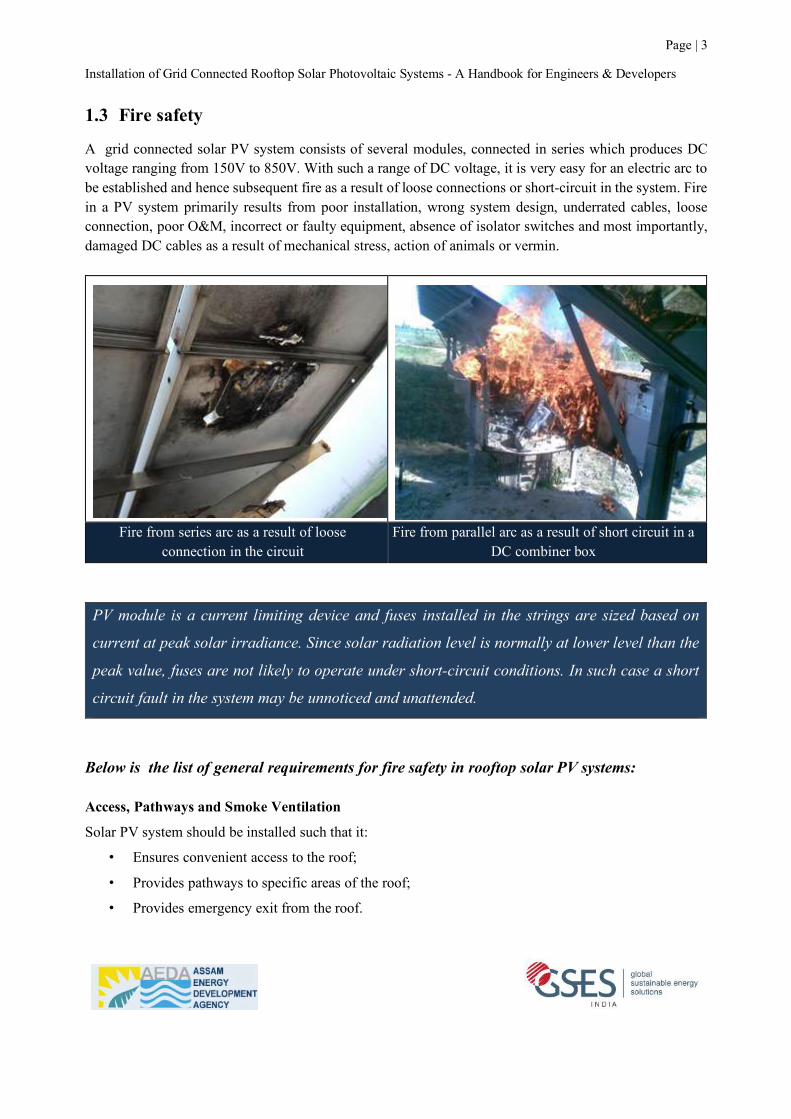
A grid connected solar PV system consists of several modules, connected in series which produces DC voltage ranging from 150V to 850V. With such a range of DC voltage, it is very easy for an electric arc to be established and hence subsequent fire as a result of loose connections or short-circuit in the system. Fire in a PV system primarily results from poor installation, wrong system design, underrated cables, loose connection, poor O&M, incorrect or faulty equipment, absence of isolator switches and most importantly, damaged DC cables as a result of mechanical stress, action of animals or vermin.
Fire from series arc as a result of loose
connection in the circuit Fire from parallel arc as a result of short circuit in a
DC combiner box PV module is a current limiting device and fuses installed in the strings are sized based on
current at peak solar irradiance. Since solar radiation level is normally at lower level than the
peak value, fuses are not likely to operate under short-circuit conditions. In such case a short
circuit fault in the system may be unnoticed and unattended.
Below is the list of general requirements for fire safety in rooftop solar PV systems: Access, Pathways and Smoke Ventilation
Solar PV system should be installed such that it:
• Ensures convenient access to the roof;
• Provides pathways to specific areas of the roof;
• Provides emergency exit from the roof.
Installation of Grid Connected Rooftop Solar Photovoltaic Systems - A Handbook for Engineers & Developers
Page | 4
Location and Routing of DC cables
• Ensure that no exposed DC cables are hanging and lying on the roof;
• All DC cables must be protected from any possible physical damage;
• DC combiner boxes should be located such that conduit runs are minimized;
• Place DC cables separately from AC cable routes and distinctly marked with “DC cables”;
• Cable trays must be covered by lid and must not have sharp edges and bends;
• When cables trays or conduits cross pathways it should be covered by a bridge made of strong and
durable material.
System Isolation
• Load breaking DC isolators must be installed to separate PV array and inverter;
• DC isolator must have mechanisms for independent manual operation;
• DC isolators will not be polarity sensitive;
• Be rated to interrupt full load and prospective fault currents from the PV array and the grid;
• Be installed in an accessible area.
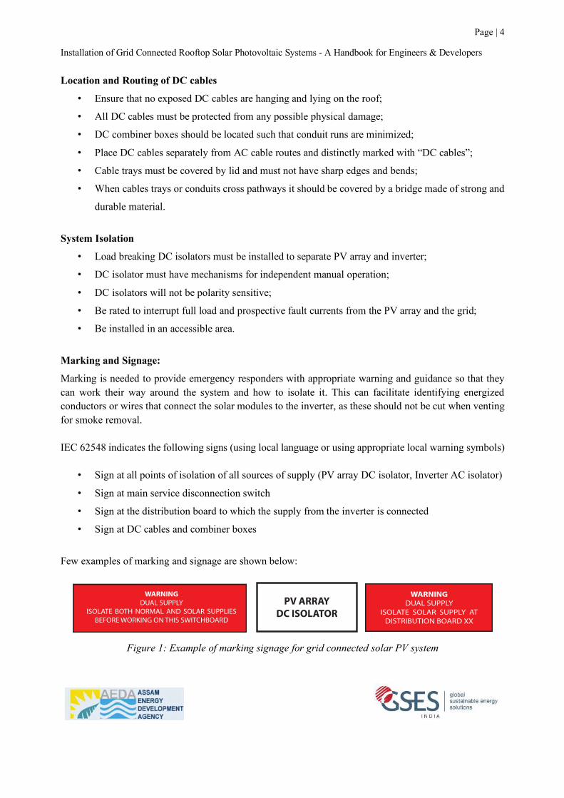
Marking and Signage:
Marking is needed to provide emergency responders with appropriate warning and guidance so that they can work their way around the system and how to isolate it. This can facilitate identifying energized conductors or wires that connect the solar modules to the inverter, as these should not be cut when venting for smoke removal. IEC 62548 indicates the following signs (using local language or using appropriate local warning symbols)
• Sign at all points of isolation of all sources of supply (PV array DC isolator, Inverter AC isolator)
• Sign at main service disconnection switch
• Sign at the distribution board to which the supply from the inverter is connected
• Sign at DC cables and combiner boxes
Few examples of marking and signage are shown below:
Figure 1: Example of marking signage for grid connected solar PV system
Page | 201Chapter 16 - System Installation
Grid-Connected PV Systems Design and Installation© GSES Pty Ltd. ver. 1.1 India
Examples of signs are given in Appendix A of the standard. Some of the required ones are:t� A “SOLAR DC” sign shall be located on all PV array and PV string junction boxes.
SOLAR D.C
t� Sign indicating “Live during Daylight” shall be attached to all DC junction boxes and switches.
LIVE DURING DAYLIGHT
t� The double pole isolator at the inverter should be labelled “PV Array DC Isolator”
PV ARRAYMAIN SWITCH
PV ARRAYDC ISOLATOR
t� Fire emergency information sign required in the main building switchboard.The following signs are also recommended in addition to the ones required:
t� The existing main switch in the switchboard should be labelled “Main Switch (Normal Supply).
MAIN SWITCH(NORMALSUPPLY)
t� The A.C. Isolator at the inverter should be labelled: “Inverter A.C. Isolator”
INVERTER ACISOLATOR
t� A warning sign in the switchboard should be installed indicating that dual supplies exist and both normal and solar supplies should be disconnected when working on the switchboard.
WARNINGDUAL SUPPLY
ISOLATE BOTH NORMAL AND SOLAR SUPPLIES BEFORE WORKING ON THIS SWITCHBOARD
t� If the grid solar system is connected on a distribution board then a warning sign should be installed in that distribution board and also in every distribution board back to and including the main switchboard.
WARNINGDUAL SUPPLY
ISOLATE SOLAR SUPPLY AT DISTRIBUTION BOARD XX
t� A sign informing people of the shutdown procedure should be located in a prominent position. This shall state the open circuit voltage and short circuit current of the array.
Installation of Grid Connected Rooftop Solar Photovoltaic Systems - A Handbook for Engineers & Developers
Page | 5
2 Rooftop Solar PV System Installation Procedure Before starting the installation process, the installer must go through all installation documents and verify the quantity and availability of listed equipment, accessories, and tools for installation and commissioning of the solar PV system. Verification of the quantity and availability must be done before starting the installation procedure to minimize the risk of project delay or an incomplete job due to non-availability or shortage of the equipment, accessories and tools. The installation and commissioning procedures for grid connected solar PV systems are presented in twelve steps. These steps are to be followed in sequence.
Step 1: Site survey and shadow analysis Step 2: Installation of PV array mounting structure Step 3: Installation and testing of structure earthing system Step 4: Installation of PV modules Step 5: Earthing of PV Module Frames Step 6: DC cabling Step 7: AC cabling and installation of inverter Step 8: System protection and safety Step 9: Placing of signage Step 10: Pre-commissioning tests Step 11: Commissioning the system Step 12: Anti-Islanding functionality test
2.1 Step 1: Site survey and shadow analysis
The site parameters that influence performance and reliability of a PV system are - access to solar radiation, near shadow and far shadow, ambient temperature, air flow and ventilation, wind speed, height of building, terrain, orientation, dust level and pollution, salinity, humidity, extreme weather conditions etc. A number of parameters are likely to be variable from one site to another even in the same geographical area. Therefore, it is crucial to plan a solar PV project to suit the site parameters and also to select the right components and customise the design accordingly to ensure better performance and safety. An inaccurate site assessment will lead to wrong design and installation of a PV system, which eventually follows into poor maintenance, poor performance and unreliable system functioning. Must have tools for site survey:
• Personal protective equipment (as applicable to site condition)
• A Solar Pathfinder or Sun eye to identify / determine shadow free area
• A compass to record direction (Mobile app is available)
• A measuring tape/ digital distance meter to measure distance
• An angle measuring equipment (Mobile app is available)
• A notebook
• A working partner (Never survey a site alone)

Installation of Grid Connected Rooftop Solar Photovoltaic Systems - A Handbook for Engineers & Developers
Page | 6
Tasks to be performed during site survey:
(1) Determine PV array location conducting shadow analysis:
• Carry out shadow analysis to find the area which is free from shadow in all days of the year
• Ensure that the PV array will have safe access for maintenance and fire safety
• Ensure that PV array has ample space for air cooling
• Ensure that modules are protected from theft and vandalism
Conduct shadow analysis at site:
Objects that come in the path of the incident solar rays any time during the day, will cast shadows and hence reduce the solar generation. A taller object located in the east direction would cast shadows during morning and a taller object located on the west direction would cast shadows during the afternoon. When multiple rows are placed, one row can cast shadow on the other if not properly placed.
Important to Note:
• Shading does not only lead to lower generation but can also damage the PV modules over a period of time
• Objective of shading analysis should not end with loss estimation but to understand and review unavoidable shadow and select appropriate inverter and optimize string design to minimize loss due to shadow.
Shadow from nearby wall Shadow from mumty
Figure 2: A small shadow during noon hours may have major impact on plant performance

Installation of Grid Connected Rooftop Solar Photovoltaic Systems - A Handbook for Engineers & Developers
Page | 7
Procedures to follow for shadow analysis: Shadow analysis – using solar pathfinder:
The most accurate and easy method to determine usable and shadow free area is by using a solar pathfinder. The Solar Pathfinder is a simple but highly accurate tool for determining shadow free area at any location. The equipment works on a reflective principle rather than actually showing shadows. It can be used anytime of the day, anytime of the year, in either cloudy or clear weather. The actual position of the sun at the time of the solar site analysis is irrelevant. The sun path diagram provided with this device is latitude specific, which provides the percentage of solar radiation available at different times of the day. By positioning the solar pathfinder at the location where an object can cast shadows, one can easily determine whether the location is shadow free or if shadow is unavoidable, how much energy will be blocked by the shadow until what time and which months of the year. The picture below shows solar pathfinder (left) and sun path diagram (right). The images seen in the solar pathfinder are objects (trees) which will create shadows at different times of the day in different months of the year.
Figure 3: Solar Pathfinder and sun path diagram (www.solarpathfinder.com) Shadow analysis – analysing sun position:
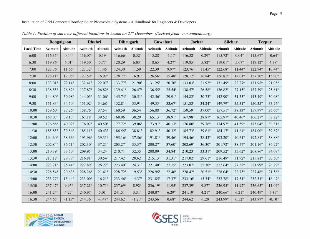
When the position and height of the object are known, it is easy to calculate shadow length at different times of the day using a simple trigonometry formula as shown below. Azimuth angle and altitude angle can be derived from various web tools that are available in web domain. One such web tool is www.suncalc.org. Table 1 below provides position of sun over different locations in Assam on 21st December. To calculate minimum distance from the objects to proposed PV array to avoid shadowing, the formula given below could be used. Consider azimuth and altitude angle on 21st December (Northern Hemisphere) to get maximum distance in the year.
Installation of Grid Connected Rooftop Solar Photovoltaic Systems - A Handbook for Engineers & Developers
Page | 8
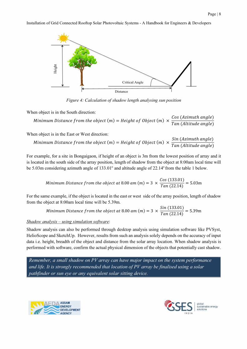
Figure 4: Calculation of shadow length analysing sun position When object is in the South direction:
"#$#%&%'#()*$+,-./%)ℎ,/12,+)(%) = 6,#7ℎ)/-812,+)(%)×:/((;<#%&)ℎ*$7=,)>*$(;=)#)&?,*$7=,)
When object is in the East or West direction:
"#$#%&%'#()*$+,-./%)ℎ,/12,+)(%) = 6,#7ℎ)/-812,+)(%)×@#$(;<#%&)ℎ*$7=,)>*$(;=)#)&?,*$7=,)
For example, for a site in Bongaigaon, if height of an object is 3m from the lowest position of array and it is located in the south side of the array position, length of shadow from the object at 8:00am local time will be 5.03m considering azimuth angle of 133.01o and altitude angle of 22.14o from the table 1 below.
"#$#%&%'#()*$+,-./%)ℎ,/12,+)*)8.00*%(%) = 3 ×:/((133.01)>*$(22.14) = 5.03m
For the same example, if the object is located in the east or west side of the array position, length of shadow from the object at 8:00am local time will be 5.39m.
"#$#%&%'#()*$+,-./%)ℎ,/12,+)*)8.00*%(%) = 3 ×@#$(133.01)>*$(22.14) = 5.39m
Shadow analysis – using simulation software:
Shadow analysis can also be performed through desktop analysis using simulation software like PVSyst, HelioScope and SketchUp. However, results from such an analysis solely depends on the accuracy of input data i.e. height, breadth of the object and distance from the solar array location. When shadow analysis is performed with software, confirm the actual physical dimension of the objects that potentially cast shadow. Remember, a small shadow on PV array can have major impact on the system performance and life. It is strongly recommended that location of PV array be finalised using a solar pathfinder or sun eye or any equivalent solar sitting device.
Hei
ght
Distance
Critical Angle
Installation of Grid Connected Rooftop Solar Photovoltaic Systems - A Handbook for Engineers & Developers
Page | 9
Table 1: Position of sun over different locations in Assam on 21st December (Derived from www.suncalc.org)
Bongaigaon Dhubri Dibrugarh Guwahati Jorhat Silchar Tezpur Local Time Azimuth Altitude Azimuth Altitude Azimuth Altitude Azimuth Altitude Azimuth Altitude Azimuth Altitude Azimuth Altitude
6:00 116.35° 0.44° 116.07° 0.19° 116.66° 0.52° 115.28° -1.17° 116.32° 0.29° 115.72° 0.04° 115.67° -0.64°
6:30 119.86° 6.01° 119.50° 5.77° 120.29° 6.03° 118.65° 4.27° 119.85° 5.82° 119.01° 5.67° 119.12° 4.78°
7:00 123.76° 11.65° 123.32° 11.45° 124.30° 11.59° 122.39° 9.97° 123.76° 11.45° 122.68° 11.44° 122.94° 10.44°
7:30 128.11° 17.06° 127.59° 16.92° 128.77° 16.91° 126.56° 15.48° 128.12° 16.84° 126.81° 17.01° 127.20° 15.90°
8:00 133.01° 22.14° 132.41° 22.07° 133.77° 21.90° 131.25° 20.70° 133.03° 21.92° 131.49° 22.27° 131.98° 21.05°
8:30 138.55° 26.82° 137.87° 26.82° 139.41° 26.47° 136.55° 25.54° 138.57° 26.58° 136.82° 27.15° 137.39° 25.81°
9:00 144.80° 30.98° 144.05° 31.06° 145.74° 30.51° 142.56° 29.91° 144.82° 30.73° 142.90° 31.53° 143.49° 30.08°
9:30 151.83° 34.50° 151.02° 34.68° 152.81° 33.91° 149.33° 33.67° 151.83° 34.24° 149.79° 35.31° 150.35° 33.74°
10:00 159.60° 37.26° 158.76° 37.54° 160.59° 36.54° 156.88° 36.72° 159.59° 37.00° 157.51° 38.33° 157.97° 36.66°
10:30 168.03° 39.13° 167.18° 39.52° 168.96° 38.29° 165.13° 38.91° 167.98° 38.87° 165.97° 40.46° 166.27° 38.72°
11:00 176.88° 40.02° 176.07° 40.50° 177.72° 39.06° 173.91° 40.13° 176.80° 39.76° 174.97° 41.59° 175.04° 39.81°
11:30 185.85° 39.86° 185.11° 40.43° 186.55° 38.81° 182.91° 40.32° 185.73° 39.61° 184.17° 41.64° 184.00° 39.87°
12:00 194.60° 38.66° 193.96° 39.31° 195.16° 37.56° 191.81° 39.46° 194.46° 38.43° 193.20° 40.61° 192.81° 38.88°
12:30 202.84° 36.51° 202.30° 37.21° 203.27° 35.37° 200.27° 37.60° 202.69° 36.30° 201.72° 38.57° 201.16° 36.92°
13:00 210.39° 33.50° 209.95° 34.24° 210.71° 32.35° 208.09° 34.84° 210.23° 33.31° 209.52° 35.62° 208.86° 34.09°
13:30 217.18° 29.77° 216.81° 30.54° 217.42° 28.62° 215.13° 31.31° 217.02° 29.61° 216.49° 31.92° 215.81° 30.50°
14:00 223.21° 25.44° 222.89° 26.22° 223.40° 24.31° 221.40° 27.15° 223.07° 25.30° 222.64° 27.58° 221.99° 26.29°
14:30 228.54° 20.63° 228.26° 21.41° 228.72° 19.53° 226.95° 22.46° 228.42° 20.51° 228.04° 22.75° 227.46° 21.58°
15:00 233.27° 15.44° 233.00° 16.21° 233.46° 14.37° 231.85° 17.37° 233.16° 15.34° 232.78° 17.51° 232.31° 16.47°
15:30 237.47° 9.95° 237.21° 10.71° 237.69° 8.92° 236.19° 11.95° 237.39° 9.87° 236.95° 11.97° 236.63° 11.04°
16:00 241.24° 4.27° 240.97° 5.01° 241.51° 3.31° 240.07° 6.29° 241.19° 4.21° 240.66° 6.21° 240.49° 5.39°
16:30 244.65° -1.15° 244.36° -0.47° 244.62° -1.20° 243.56° 0.68° 244.62° -1.20° 243.99° 0.52° 243.97° -0.10°
Installation of Grid Connected Rooftop Solar Photovoltaic Systems - A Handbook for Engineers & Developers
Page | 10
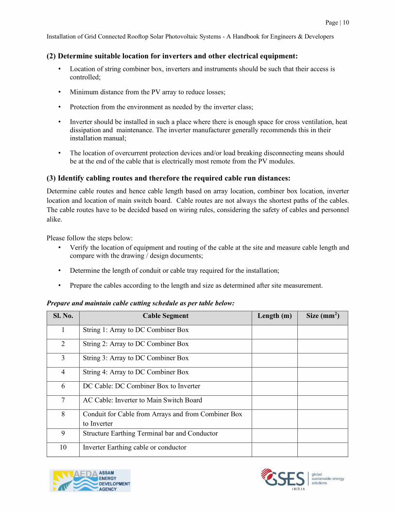
(2) Determine suitable location for inverters and other electrical equipment: • Location of string combiner box, inverters and instruments should be such that their access is
controlled;
• Minimum distance from the PV array to reduce losses;
• Protection from the environment as needed by the inverter class;
• Inverter should be installed in such a place where there is enough space for cross ventilation, heat dissipation and maintenance. The inverter manufacturer generally recommends this in their installation manual;
• The location of overcurrent protection devices and/or load breaking disconnecting means should be at the end of the cable that is electrically most remote from the PV modules.
(3) Identify cabling routes and therefore the required cable run distances: Determine cable routes and hence cable length based on array location, combiner box location, inverter location and location of main switch board. Cable routes are not always the shortest paths of the cables. The cable routes have to be decided based on wiring rules, considering the safety of cables and personnel alike. Please follow the steps below:
• Verify the location of equipment and routing of the cable at the site and measure cable length and compare with the drawing / design documents;
• Determine the length of conduit or cable tray required for the installation;
• Prepare the cables according to the length and size as determined after site measurement.
Prepare and maintain cable cutting schedule as per table below:
Sl. No. Cable Segment Length (m) Size (mm2)
1 String 1: Array to DC Combiner Box
2 String 2: Array to DC Combiner Box
3 String 3: Array to DC Combiner Box
4 String 4: Array to DC Combiner Box
6 DC Cable: DC Combiner Box to Inverter
7 AC Cable: Inverter to Main Switch Board
8 Conduit for Cable from Arrays and from Combiner Box to Inverter
9 Structure Earthing Terminal bar and Conductor
10 Inverter Earthing cable or conductor
Installation of Grid Connected Rooftop Solar Photovoltaic Systems - A Handbook for Engineers & Developers
Page | 11
2.2 Step 2: Installation of PV array mounting structure Failure of PV array mounting structures due to strong winds is a rising concern in Indian solar projects today. It is very common for PV array mounting structures to be conceptualised and designed primarily to enhance energy generation considering area specific tilt angle and use of tracking facility etc. A large number of solar PV systems are reported to be damaged due to inadequate design consideration for wind loading. Apart from the strength and wind loading capacity, a mounting structure must ensure that the PV array receives optimum solar radiation and reduces temperatures loss by allowing enough air circulation. It is also important to ensure that factors such as structure design, placement, orientation, tilt and shading are aligned with electrical string design and choice of inverter. Wind loading on PV array mounting structure: The entire state of Assam falls under “Very high damage risk zone A and zone B” with basic wind speed of 180km/ hour and above according to IS 875 Part 3: Wind Loads on Buildings and Structure. The PV array mounting structure for any site in Assam shall be designed to withstand not less than 180km per hour wind speed for the areas under zone B and 200km per hour wind speed for the areas under zone A. Design of wind pressure must be calculated over basic wind speed, multiplying by the factors derived for - height of the building, topography, pressure coefficient based on roof type and slope, exposure category and importance factor as per IS 875 (Part 3) or ASCE-7. Table 2 in this handbook provides ready reference of design wind load at different roof heights for 180km per hour wind speed. This table has been specifically prepared for the state of Assam and can be used for preliminary assessment of design wind load at different roof heights in wind zone B. However, the actual design load is likely to vary, based on the specific site parameters. The design wind load provided in the table 2 is per unit projected area (m2) normal to the wind. Therefore, total wind pressure on a structure will be proportionate to the total projected area of the structure normal to the wind.
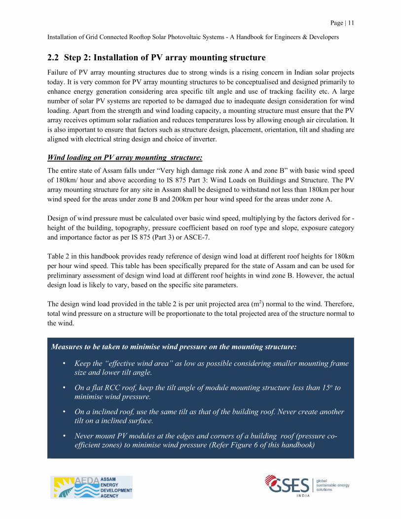
Measures to be taken to minimise wind pressure on the mounting structure:
• Keep the “effective wind area” as low as possible considering smaller mounting frame size and lower tilt angle.
• On a flat RCC roof, keep the tilt angle of module mounting structure less than 15o to minimise wind pressure.
• On a inclined roof, use the same tilt as that of the building roof. Never create another tilt on a inclined surface.
• Never mount PV modules at the edges and corners of a building roof (pressure co-efficient zones) to minimise wind pressure (Refer Figure 6 of this handbook)

Installation of Grid Connected Rooftop Solar Photovoltaic Systems - A Handbook for Engineers & Developers
Page | 12
Figure 5: India Wind Zone Map (Source IS875 Part 3)

Installation of Grid Connected Rooftop Solar Photovoltaic Systems - A Handbook for Engineers & Developers
Page | 13
Table 2: Reference table for design wind load for mounting structure at different roof height
Mean Roof Height
Velocity Pressure Exposure
Coefficients based on height
Design wind load (kg-force/m2
projected area normal to the wind)
Counter load considering 50% safety factor (kg-
force/m2)
Volume of concrete (m3) if PCC pedestal
is used
ft m Exposure C
Exposure D
Exposure C
Exposure D
Exposure C
Exposure D
Exposure C
Exposure D
15 4.57 0.85 1.03 133 161 199 241 0.083 0.100
20 6.10 0.90 1.08 140 168 210 253 0.088 0.105 25 7.62 0.94 1.12 147 175 220 262 0.092 0.109
30 9.14 0.98 1.16 153 181 229 271 0.095 0.113
40 12.19 1.04 1.22 162 190 243 285 0.101 0.119
50 15.24 1.09 1.27 170 198 255 297 0.106 0.124 60 18.29 1.13 1.31 176 204 264 306 0.110 0.128
70 21.34 1.17 1.34 182 209 274 313 0.114 0.131
80 24.38 1.21 1.38 189 215 283 323 0.118 0.134
90 27.43 1.24 1.40 193 218 290 327 0.121 0.136 100 30.48 1.26 1.43 196 223 295 334 0.123 0.139
120 36.58 1.31 1.48 204 231 306 346 0.128 0.144
140 42.67 1.36 1.52 212 237 318 355 0.133 0.148
160 48.77 1.39 1.55 217 242 325 363 0.135 0.151 180 54.86 1.43 1.58 223 246 334 370 0.139 0.154
200 60.96 1.46 1.61 228 251 341 377 0.142 0.157
Note: This table is for reference purpose to readily assess design wind load for a rooftop PV site in the state of Assam (wind zone B). Actual design load may vary based on the specific site parameters.
Assumptions:
F = qz x G x Cf x Af (N) [Design wind load on open building and other structure Equation 6-25 of ASCE7]
qz= 0.613 x Kz x Kzt x Kd x V2 x I [Velocity pressure evaluated using equation 6.5.10 of ASCE7]
Kz = Velocity pressure exposure coefficient from Table 6-3 of ASCE7
Kzt = Topographic Factor = 1.0 (From Figure 6-4 of ASCE7)
Kd = Wind directionality factor = 0.85 (Table 6-4 of ASCE7)
V = Basic wind speed =50 m/s (very high damaged risk zone B)
G = Gust effect factor = 0.85 for rigid structure (Section 6.5.8.1 of ASCE7)]
Cf = Net force co-efficient = 1.2 (from figure 6-20 of ASCE7 ratio of height to width <=3)
Af = Projected area normal to the wind = 1m2
I =1.15 Importance factor = 1.15 for III and IV category structure
Exposure C is applicable to open terrain with obstruction heights 10m or less. Exposure D is applicable to flat, unobstructed areas and water surfaces where the terrain prevails for at least 1524m or 10 times the structure height, whichever is greater. Extends inland from the shoreline for 200m, or 10 times the structure height, whichever is greater.

Installation of Grid Connected Rooftop Solar Photovoltaic Systems - A Handbook for Engineers & Developers
Page | 14
Gable Roof with tilt >7o <=45 o
Hip Roof with tilt >7 o <=45 o
a = 10% of least horizontal dimension or 0.4h (mean roof height) whichever is smaller but not less than 4% od least horizontal dimension
Figure 6: Pressure coefficient zones in a building (Source: ASCE7-05)
Protection against corrosion: The steel structure will be hot dip galvanised and the aluminium structure will be anodized. These coatings protect the structure from corrosion. Do not drill, weld or cut the structure at the site. This will damage the coating and corrosion will be accelerated..
Do not drill Do not weld Do not cut
Figure 7: Damaging of coating of structure will accelerate corrosion
Installation of Grid Connected Rooftop Solar Photovoltaic Systems - A Handbook for Engineers & Developers
Page | 15
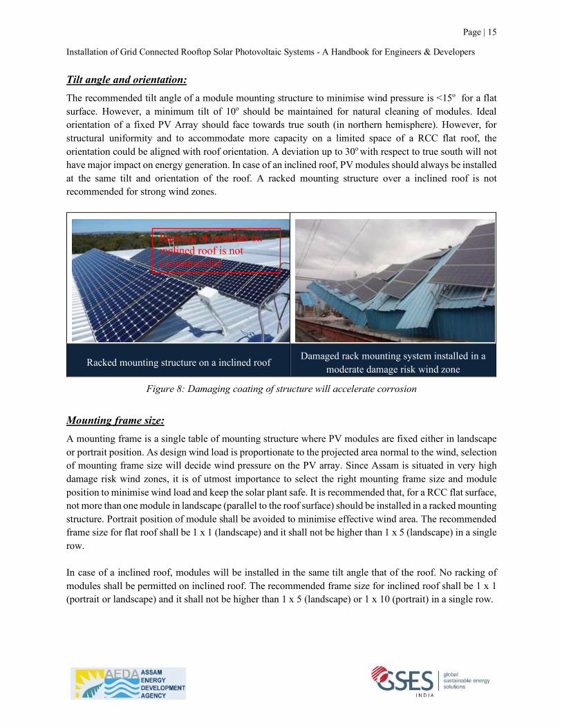
Tilt angle and orientation: The recommended tilt angle of a module mounting structure to minimise wind pressure is <15o for a flat surface. However, a minimum tilt of 10o should be maintained for natural cleaning of modules. Ideal orientation of a fixed PV Array should face towards true south (in northern hemisphere). However, for structural uniformity and to accommodate more capacity on a limited space of a RCC flat roof, the orientation could be aligned with roof orientation. A deviation up to 30o with respect to true south will not have major impact on energy generation. In case of an inclined roof, PV modules should always be installed at the same tilt and orientation of the roof. A racked mounting structure over a inclined roof is not recommended for strong wind zones.
Racked mounting structure on a inclined roof Damaged rack mounting system installed in a moderate damage risk wind zone
Figure 8: Damaging coating of structure will accelerate corrosion
Mounting frame size: A mounting frame is a single table of mounting structure where PV modules are fixed either in landscape or portrait position. As design wind load is proportionate to the projected area normal to the wind, selection of mounting frame size will decide wind pressure on the PV array. Since Assam is situated in very high damage risk wind zones, it is of utmost importance to select the right mounting frame size and module position to minimise wind load and keep the solar plant safe. It is recommended that, for a RCC flat surface, not more than one module in landscape (parallel to the roof surface) should be installed in a racked mounting structure. Portrait position of module shall be avoided to minimise effective wind area. The recommended frame size for flat roof shall be 1 x 1 (landscape) and it shall not be higher than 1 x 5 (landscape) in a single row. In case of a inclined roof, modules will be installed in the same tilt angle that of the roof. No racking of modules shall be permitted on inclined roof. The recommended frame size for inclined roof shall be 1 x 1 (portrait or landscape) and it shall not be higher than 1 x 5 (landscape) or 1 x 10 (portrait) in a single row.
Racking of modules on inclined roof is not recommended

Installation of Grid Connected Rooftop Solar Photovoltaic Systems - A Handbook for Engineers & Developers
Page | 16
Mounting structure for single module installed in landscape position with 10-15 o tilt is best suited for
the wind zones with very high damage risk.
Figure 9: Recommended PV array mounting structure for RCC flat roof in Assam
PV array mounted with larger effective wind area
likely to be damaged by strong wind PV arrays installed with large mounting frame
size damaged by wind
Figure 10: PV array mounting structure with larger frame size is not recommended for Assam
Determining space between two rows: Space between two rows can be determined by analysing the sun’s position for winter solstice (21st December) as explained in the procedures for shadow analysis. In this case, the object that will create shadow is the PV array (row) on the south. The minimum space between two rows shall be higher than maximum length of the shadow at desired time of the day say, 8.00am in the morning and 3.00pm in the afternoon (local time) for lowest position of sun on 21st December. The length of the shadow will be determined by the azimuth and altitude of the sun during the desired time and differential height of the lowest point of the row in the north and highest point of the row in the south.
Recommended PV array mounting structure for RCC flat roofs in Assam

Installation of Grid Connected Rooftop Solar Photovoltaic Systems - A Handbook for Engineers & Developers
Page | 17
Figure 11: Calculation space between two rows analysing sun position Using the same example, for the site in Bongaigaon, if width of the module frame is 2m and tilt angle is 15o, differential height (x) between two rows will be 0.52m. Maximum shadow length at 8:00am local time on 21st December will be 0.87m and maximum shadow length at 3.00pm local time on 21st December will be 1.13m. Therefore, minimum gap between two rows shall be 1.13m for a tilt angle of 15o. If the tilt angle is increased or frame size of the mounting structure is increased, gap between two rows will also be increased accordingly. "#$$%&%'(#)*ℎ%#,ℎ(-%(.%%'*/.%0()'1ℎ#,%0(2/#'(0/$&/.0(4) = 289#'(15) = 0.52m
?)8#4@40ℎ)1/.*%',ℎ($&/40/@(ℎ&/.)(8.00)4(4) = 0.52 ×C/0(133.01)E)'(22.14)
= 0.87m
?)8#4@40ℎ)1/.*%',ℎ($&/40/@(ℎ&/.)(3.0024(4) = 0.52 ×C/0(233.27)E)'(15.44)
= 1.13m
Access to PV modules for maintenance: While installing PV arrays on RCC flat roof, leave adequate space from the parapet wall to avoid shadow on the modules as well as for convenient movement of maintenance personnel. This can be determined by analysing sun position and height of the parapet wall as described earlier. A minimum gap of 0.5m between two rows should be maintained for movement of maintenance personnel for cleaning or other maintenance work. When modules are installed on an inclined roof, , adequate gap between two rows and frames must be kept as such that maintenance personnel can reach to each corner of the modules without stepping on to it. An additional walkway may be provided in between the rows to enable safe cleaning and maintenance of PV modules.
Row in the South Row in the North
Installation of Grid Connected Rooftop Solar Photovoltaic Systems - A Handbook for Engineers & Developers
Page | 18
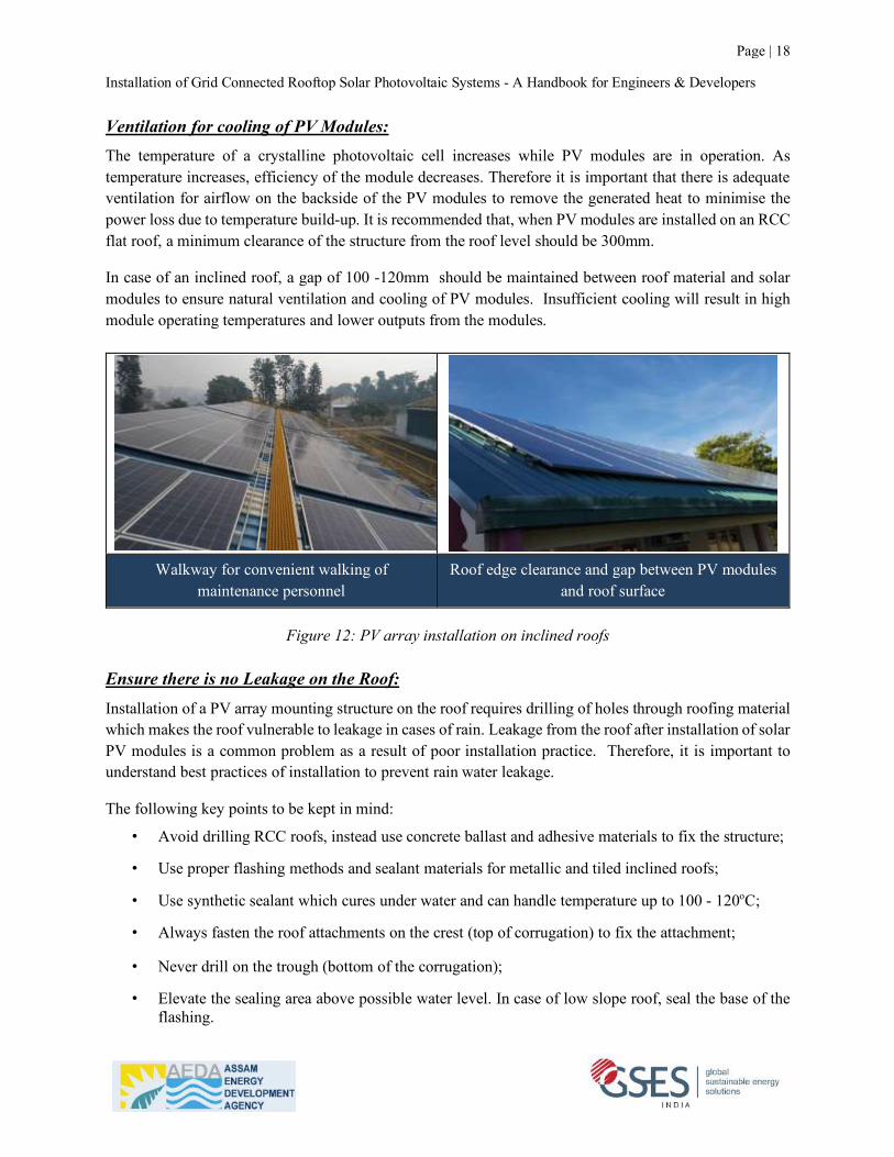
Ventilation for cooling of PV Modules: The temperature of a crystalline photovoltaic cell increases while PV modules are in operation. As temperature increases, efficiency of the module decreases. Therefore it is important that there is adequate ventilation for airflow on the backside of the PV modules to remove the generated heat to minimise the power loss due to temperature build-up. It is recommended that, when PV modules are installed on an RCC flat roof, a minimum clearance of the structure from the roof level should be 300mm.
In case of an inclined roof, a gap of 100 -120mm should be maintained between roof material and solar modules to ensure natural ventilation and cooling of PV modules. Insufficient cooling will result in high module operating temperatures and lower outputs from the modules.
Walkway for convenient walking of
maintenance personnel Roof edge clearance and gap between PV modules
and roof surface
Figure 12: PV array installation on inclined roofs Ensure there is no Leakage on the Roof: Installation of a PV array mounting structure on the roof requires drilling of holes through roofing material which makes the roof vulnerable to leakage in cases of rain. Leakage from the roof after installation of solar PV modules is a common problem as a result of poor installation practice. Therefore, it is important to understand best practices of installation to prevent rain water leakage.
The following key points to be kept in mind:
• Avoid drilling RCC roofs, instead use concrete ballast and adhesive materials to fix the structure;
• Use proper flashing methods and sealant materials for metallic and tiled inclined roofs;
• Use synthetic sealant which cures under water and can handle temperature up to 100 - 120oC;
• Always fasten the roof attachments on the crest (top of corrugation) to fix the attachment;
• Never drill on the trough (bottom of the corrugation);
• Elevate the sealing area above possible water level. In case of low slope roof, seal the base of the flashing.
Installation of Grid Connected Rooftop Solar Photovoltaic Systems - A Handbook for Engineers & Developers
Page | 19
2.3 Step 3: Installation and testing of structure earthing system After installation of module mounting structure, the next step is to provide a continuous equipotential bond between mounting structure and module frames. Following procedures to be followed:
(1) Verify the earthing conductor routing plan;
(2) Prepare earth terminal bar / conductor, lugs, clamps, earthing rod and earth pit as per drawing;
(3) Ensure all module frames and each part of mounting structure are electrically bonded;
(4) Use proper WEEB for bonding;
(5) Find the best location for earthing pit where soil is wet and resistivity is least;
(6) Attach the earthing terminal bar /wire with earthing rod;
(7) Connect terminal bar to structure;
(8) Ensure all the connections are neat and tight;
(9) Test earthing continuity and resistance of earth electrode after installation.
The conductor used to earth the exposed metallic frames of the PV array shall have a minimum size of 6mm2 copper or equivalent if there is no lightning system installed for the system. When a lightning protection system is installed, minimum size of the conductor shall be 16mm2 copper or equivalent. PV array bonding conductors should run as close to the positive and negative PV array and or sub-array conductors as possible to reduce induced voltages due to lightning.
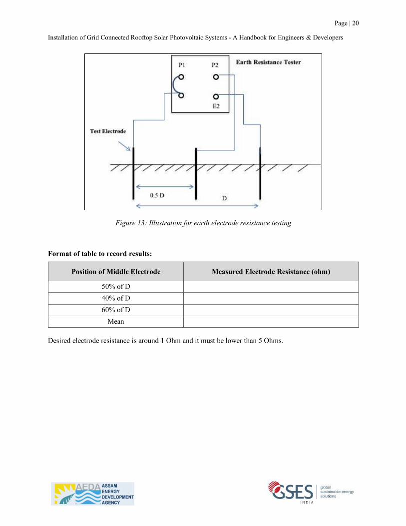
Procedure for measurement of earthing continuity and earth electrode resistance using earth resistance tester – Follow in sequence (1) Short the P1 and E1 terminal of the Earth resistance tester;
(2) Connect the electrode under test to E1 terminal of earth resistance tester;
(3) Using a hammer, dig an electrode at a distance (D) of minimum 30 meter from the test Electrode;
(4) Connect this electrode to E2 terminal of earth resistance tester;
(5) Using a hammer, dig another electrode in between both the electrodes at 50% of D;
(6) Connect this electrode to P2 of the terminal;
(7) Take reading by rotating the handle of Earth resistance tester or press push button;
(8) Repeat the above procedure by changing the location of middle electrode to 40% and 60% of D;
(9) To get the resistance of electrode, take mean of these three readings.
Installation of Grid Connected Rooftop Solar Photovoltaic Systems - A Handbook for Engineers & Developers
Page | 20
Figure 13: Illustration for earth electrode resistance testing
Format of table to record results:
Position of Middle Electrode Measured Electrode Resistance (ohm)
50% of D 40% of D 60% of D
Mean Desired electrode resistance is around 1 Ohm and it must be lower than 5 Ohms.

Installation of Grid Connected Rooftop Solar Photovoltaic Systems - A Handbook for Engineers & Developers
Page | 21
2.4 Step 4: Installation of PV modules Modules should be installed after the earthing system of structure is completely constructed. It is important for the installer to know properly about handling, packaging and storage of PV modules so that modules do not get damaged during the process of installation. Please follow the instruction given in this handbook carefully while handling, storing and installing the PV modules.
Important to Note:
Do NOT connect the modules in the strings while fixing the modules in the structure. This will produce high DC voltage, which is extremely dangerous for the installer. Connection will be done at a later stage.
(1) Handling and Packaging:
• Solar modules should be stacked, packed and transported vertically and separators should be placed between each module. Horizontal stacking should be avoided.
• If due to unavoidable reasons, the modules are required to be stacked horizontally, introduction of a good buffer material between each module and around the modules is necessary to reduce potential damage. Also, additional protection is to be added to the four corners of each module and not more than six modules should be packed in one box.
Solar modules should be stacked, packed and
transported vertically If stacked horizontally, NOT more than six modules
should be packed in one box
Figure 14: Correct way of packing modules
Installation of Grid Connected Rooftop Solar Photovoltaic Systems - A Handbook for Engineers & Developers
Page | 22
Important to Note:
Horizontally stacking the modules causes stress on the modules at the bottom and can lead to micro-cracks that will be not be detected by naked eyes. Even if the separators are used, they are not strong and wide enough to sufficiently separate the modules from each other, thus the upper layers of the stack cause weight stress towards the lower layers that leads to micro-cracks in the cells.
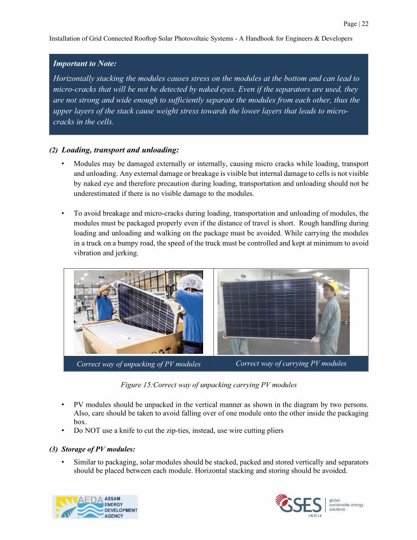
(2) Loading, transport and unloading:
• Modules may be damaged externally or internally, causing micro cracks while loading, transport and unloading. Any external damage or breakage is visible but internal damage to cells is not visible by naked eye and therefore precaution during loading, transportation and unloading should not be underestimated if there is no visible damage to the modules.
• To avoid breakage and micro-cracks during loading, transportation and unloading of modules, the modules must be packaged properly even if the distance of travel is short. Rough handling during loading and unloading and walking on the package must be avoided. While carrying the modules in a truck on a bumpy road, the speed of the truck must be controlled and kept at minimum to avoid vibration and jerking.
Correct way of unpacking of PV modules Correct way of carrying PV modules
Figure 15:Correct way of unpacking carrying PV modules
• PV modules should be unpacked in the vertical manner as shown in the diagram by two persons.
Also, care should be taken to avoid falling over of one module onto the other inside the packaging box.
• Do NOT use a knife to cut the zip-ties, instead, use wire cutting pliers
(3) Storage of PV modules:
• Similar to packaging, solar modules should be stacked, packed and stored vertically and separators should be placed between each module. Horizontal stacking and storing should be avoided.
Installation of Grid Connected Rooftop Solar Photovoltaic Systems - A Handbook for Engineers & Developers
Page | 23
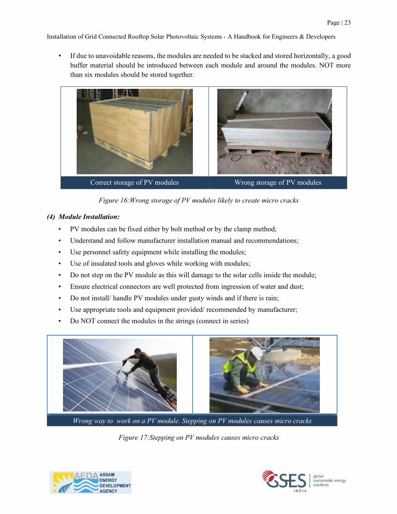
• If due to unavoidable reasons, the modules are needed to be stacked and stored horizontally, a good buffer material should be introduced between each module and around the modules. NOT more than six modules should be stored together.
Correct storage of PV modules Wrong storage of PV modules
Figure 16:Wrong storage of PV modules likely to create micro cracks
(4) Module Installation:
• PV modules can be fixed either by bolt method or by the clamp method; • Understand and follow manufacturer installation manual and recommendations; • Use personnel safety equipment while installing the modules; • Use of insulated tools and gloves while working with modules; • Do not step on the PV module as this will damage to the solar cells inside the module; • Ensure electrical connectors are well protected from ingression of water and dust; • Do not install/ handle PV modules under gusty winds and if there is rain; • Use appropriate tools and equipment provided/ recommended by manufacturer; • Do NOT connect the modules in the strings (connect in series)
Wrong way to work on a PV module. Stepping on PV modules causes micro cracks
Figure 17:Stepping on PV modules causes micro cracks
Installation of Grid Connected Rooftop Solar Photovoltaic Systems - A Handbook for Engineers & Developers
Page | 24
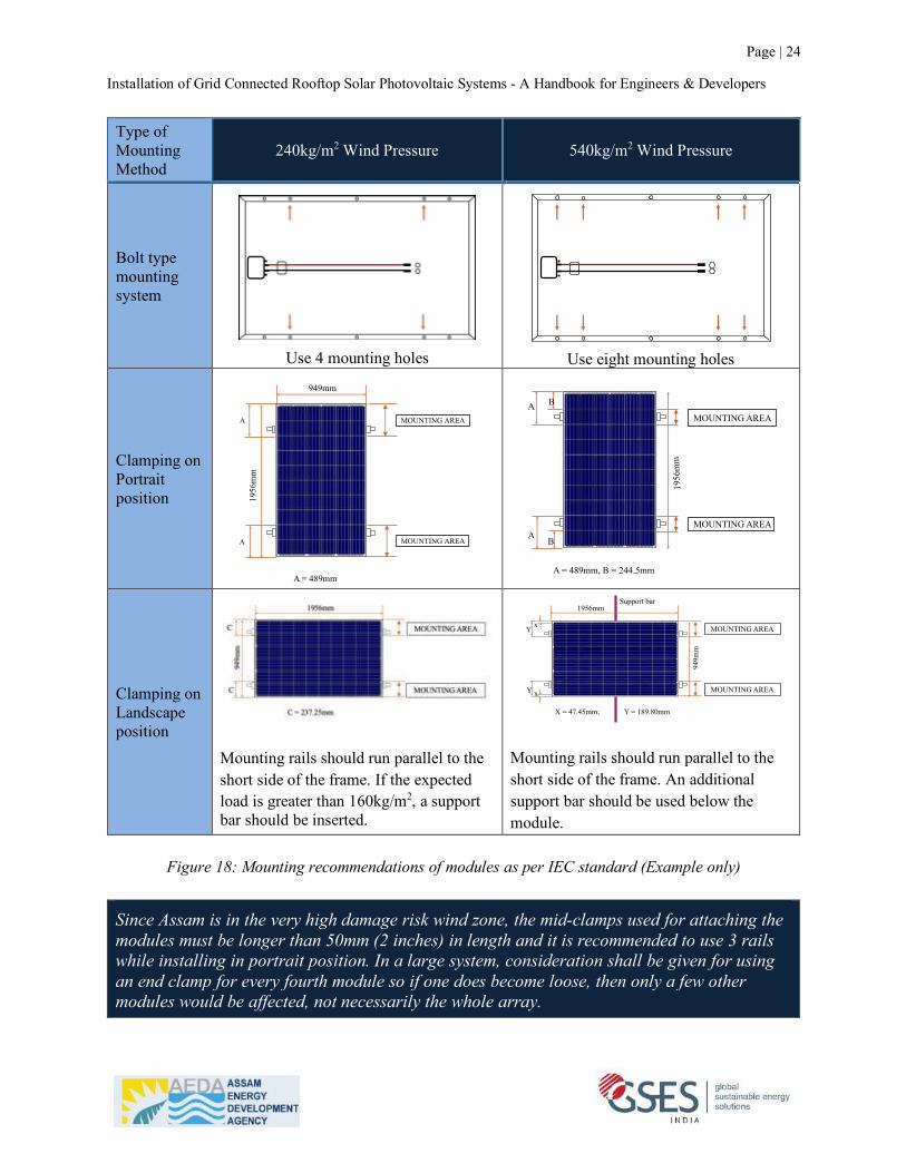
Type of Mounting Method
240kg/m2 Wind Pressure 540kg/m2 Wind Pressure
Bolt type mounting system
Use 4 mounting holes
Use eight mounting holes
Clamping on Portrait position
Clamping on Landscape position
Mounting rails should run parallel to the short side of the frame. If the expected load is greater than 160kg/m2, a support bar should be inserted.
Mounting rails should run parallel to the short side of the frame. An additional support bar should be used below the module.
Figure 18: Mounting recommendations of modules as per IEC standard (Example only)
Since Assam is in the very high damage risk wind zone, the mid-clamps used for attaching the modules must be longer than 50mm (2 inches) in length and it is recommended to use 3 rails while installing in portrait position. In a large system, consideration shall be given for using an end clamp for every fourth module so if one does become loose, then only a few other modules would be affected, not necessarily the whole array.
MOUNTING AREA
MOUNTING AREA
A
A
1956
mm
949mm
A = 489mm
MOUNTING AREA
MOUNTING AREA
A B
AB
1956
mm
A = 489mm, B = 244.5mm
x
xY
Y
Support bar
949m
m
1956mm
X = 47.45mm; Y = 189.80mm
MOUNTING AREA
MOUNTING AREA
Page | 25
Installation of Grid Connected Rooftop Solar Photovoltaic Systems - A Handbook for Engineers & Developers
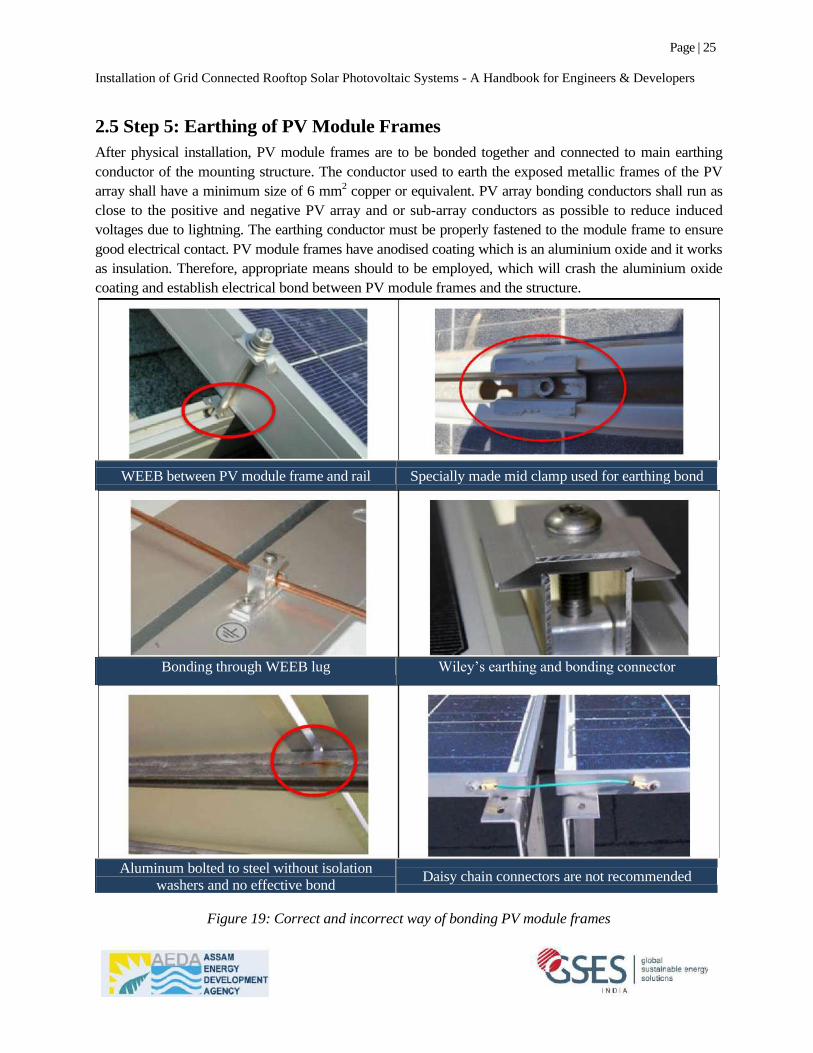
2.5 Step 5: Earthing of PV Module Frames
After physical installation, PV module frames are to be bonded together and connected to main earthing
conductor of the mounting structure. The conductor used to earth the exposed metallic frames of the PV
array shall have a minimum size of 6 mm2 copper or equivalent. PV array bonding conductors shall run as
close to the positive and negative PV array and or sub-array conductors as possible to reduce induced
voltages due to lightning. The earthing conductor must be properly fastened to the module frame to ensure
good electrical contact. PV module frames have anodised coating which is an aluminium oxide and it works
as insulation. Therefore, appropriate means should to be employed, which will crash the aluminium oxide
coating and establish electrical bond between PV module frames and the structure.
WEEB between PV module frame and rail Specially made mid clamp used for earthing bond
Bonding through WEEB lug Wiley’s earthing and bonding connector
Aluminum bolted to steel without isolation
washers and no effective bond Daisy chain connectors are not recommended
Figure 19: Correct and incorrect way of bonding PV module frames
Installation of Grid Connected Rooftop Solar Photovoltaic Systems - A Handbook for Engineers & Developers
Page | 26
2.6 Step 6: DC cabling It is important to minimise voltage drop loss in the cables for a desired performance of solar PV systems. Ensure that aggregate voltage drop in all DC cables is less than 3% as recommended by IEC 62548 PV array design requirements. Voltage drop in DC cables can calculated using formula below:
Where, HIJJKLMN= Route length of DC cable in meters (multiply by 2 for total circuit wire length) OIJ = DC current in amperes ρ = Resistivity of the wire in Ω/m/mm2 (For copper ρ = 0.0183 Ω/m/mm2) PIJJKLMN = Cross sectional area (CSA) of DC cable in mm2
H/00 = Q/*(),%1&/2#'% Vmp string= String Voltage (No. of modules in string x Vmp at maximum temperature)
(1) Module wiring or stringing
After physical installation and establishment of earthing bond of the frames, PV modules are connected in series electrically to form a string. Precautions to take while wiring modules:
• Only a trained and qualified installer should perform all wiring;
• Use stainless steel clamp or UV protected cable tie to fix cables;
• DO NOT connect all the module in series to avoid high DC voltage;
• Final connection will be done when the system is ready for commissioning;
• Ensure electrical connectors are well protected against corrosion and soiling;
• Ensure that connectors are corrosion free, cleaned with absolutely no gaps between the contacts;
• DO NOT allow any inflammable liquids/gases near installation area.
Important to Note:
While connecting modules, each string should have one MC4 disconnected until all wiring to the DC combiner box has been completed. This is to ensure that no one is working on live dangerous DC voltage.
A!" !!"#$% =2!!!!!" !!"#$% !!!!!" !!!!!"##!!!!!"!!"#$%&
Installation of Grid Connected Rooftop Solar Photovoltaic Systems - A Handbook for Engineers & Developers
Page | 27
Follow the steps below in sequence for module wiring or stringing:
(1) Review the DC cable wiring diagram;
(2) Review module interconnection (string or series) diagram;
(3) Check that there isn’t any bare cable in module wire;
(4) Connect DC cable connector (MC4 or equivalent) properly with crimping tool;
(5) Connect number of modules in series in accordance with the wiring diagram provided;
(6) Attach the cables with cable tie wraps to the module frame and/or rails;
(7) Ensure minimum looping in cable;
(8) Ensure NO cable is hanging loose;
(9) Label the terminals with “+” and “-”sign using cable tag.
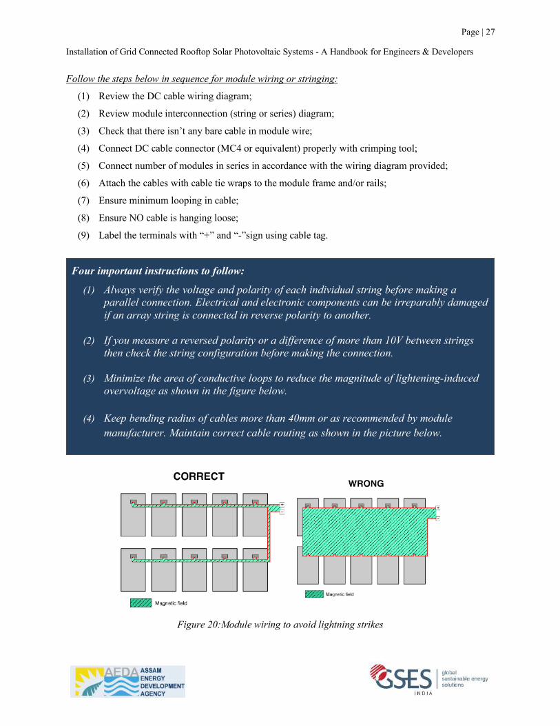
Four important instructions to follow:
(1) Always verify the voltage and polarity of each individual string before making a parallel connection. Electrical and electronic components can be irreparably damaged if an array string is connected in reverse polarity to another.
(2) If you measure a reversed polarity or a difference of more than 10V between strings then check the string configuration before making the connection.
(3) Minimize the area of conductive loops to reduce the magnitude of lightening-induced
overvoltage as shown in the figure below.
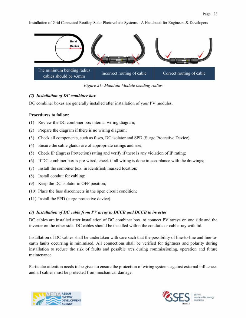
(4) Keep bending radius of cables more than 40mm or as recommended by module manufacturer. Maintain correct cable routing as shown in the picture below.
Figure 20:Module wiring to avoid lightning strikes
Installation of Grid Connected Rooftop Solar Photovoltaic Systems - A Handbook for Engineers & Developers
Page | 28
The minimum bending radius
cables should be 43mm Incorrect routing of cable Correct routing of cable
Figure 21: Maintain Module bending radius
(2) Installation of DC combiner box
DC combiner boxes are generally installed after installation of your PV modules. Procedures to follow:
(1) Review the DC combiner box internal wiring diagram;
(2) Prepare the diagram if there is no wiring diagram;
(3) Check all components, such as fuses, DC isolator and SPD (Surge Protective Device);
(4) Ensure the cable glands are of appropriate ratings and size;
(5) Check IP (Ingress Protection) rating and verify if there is any violation of IP rating;
(6) If DC combiner box is pre-wired, check if all wiring is done in accordance with the drawings;
(7) Install the combiner box in identified/ marked location;
(8) Install conduit for cabling;
(9) Keep the DC isolator in OFF position;
(10) Place the fuse disconnects in the open circuit condition;
(11) Install the SPD (surge protective device).
(3) Installation of DC cable from PV array to DCCB and DCCB to inverter
DC cables are installed after installation of DC combiner box, to connect PV arrays on one side and the inverter on the other side. DC cables should be installed within the conduits or cable tray with lid. Installation of DC cables shall be undertaken with care such that the possibility of line-to-line and line-to-earth faults occurring is minimised. All connections shall be verified for tightness and polarity during installation to reduce the risk of faults and possible arcs during commissioning, operation and future maintenance. Particular attention needs to be given to ensure the protection of wiring systems against external influences and all cables must be protected from mechanical damage.
Date: April, 2016 DOC: PS-M-0434 A Page - 13 - of 15
N No modules in series
Voc Open circuit voltage of each module (refer to product label or data sheet)
TCvoc Thermal coefficient of open circuit voltage for the module (refer to data sheet)
Tmin The lowest ambient temperature
• Each module have two standards 90°C sunlight resistant output cables each terminated with plug & play connectors. The wire type and gauge of the output cables are 1000V (For TSM-PE05A.**, PE14A.** which are 1500V DC) rated PV Wire cable and are 12AWG in size. This cable is suitable for applications where wiring is exposed to the direct sunlight. We require that all wiring and electrical connections comply with the appropriate National Electrical Code.
• The minimum and maximum outer diameters of the cable are 5 to 7mm(0.038 to 0.076in2). • For field connections, use at least 4mm2 copper wires insulated for a minimum of 90°C and sunlight resistance
with insulation designated as PV Wire. • The minimum bending radius cables should be 43mm(1.69in).
7. ELECTRICAL CONFIGURATION
Photovoltaic (electric) systems operate automatically and require very little day-to-day supervision. The solar array generates DC electricity whenever light falls on it similarly the inverter automatically turns ON as soon as there is sufficient energy from the solar array to efficiently convert this into grid.
*Caution: • The module is rated to operate at potentially lethal DC voltages which have the potential can cause severe
electrical shock, arcing and fire hazards. Whilst some solar modules, manufactured by Trina Solar, are certified to operate up to 1000V DC (For TSM-PE05A.**,PE14A.**, to 1500V DC) always check the module label to confirm the actual rating of your product before making connections.
• It is recommended to use a suitably rated isolator (DC switch) to interrupt the current flow before disconnecting the connectors.
7.1 FUSING • When fuses are fitted they should be rated for the maximum DC voltage and connected in each, non-grounded
pole of the array (i.e. if the system is not grounded then fuses should be connected in both the positive and negative poles).
• The maximum rating of a fuse connected in series with an array string is typically 15A but the actual module specific rating can be found on the product label and in the product datasheet.
• This fuse rating value also corresponds to the maximum reverse current that a module can withstand (when one string is shaded then the other parallel strings of modules will be loaded by the shaded string and current will flow) and therefore impacts the number of strings in parallel.
7.2 INVERTER SELETION AND COMPATIBILITY • When installed in systems governed by IEC regulations, Trina Solar modules normally do not need to be
electronically connected to earth and therefore can be operated together with either galvanically isolated (with transformer) and transformerless inverters.
• Potential Induced Degradation (PID) is sometimes observed in PV modules due to a combination of high humidity, high temperature and high voltage. PID is most likely to cause degradation under the following conditions: a) Installations in the warm and humid climates b) Installation close to a source of continual moisture, such as bodies of water
• To reduce the risk of PID, we strongly suggest that modules feature Trina Solar’s Anti-PID technology, which
Incorrect Routing of cable Correct Routing of cable
Installation of Grid Connected Rooftop Solar Photovoltaic Systems - A Handbook for Engineers & Developers
Page | 29
Procedures to follow:
(1) Review the DC wiring diagram;
(2) Install conduit/ cable tray from roof to DC combiner box;
(3) Secure all conduits/ cable trays to the building;
(4) Pull the DC cables through conduit/ cable tray from roof to the DC combiner box;
(5) Leave excess wire at both ends (roof and combiner Box);
(6) Use sealing materials (silicone) to prevent leakage into the conduit and the penetration at roof;
(7) Terminate DC cables in DC combiner box;
(8) Install cable connectors (MC4 or equivalent) at both ends and tag cable with “+” and “-“ sign;
(9) Tighten the cable connector using appropriate tools;
(10) Test the cables to ensure correct polarity labelling;
(11) Keep all connectors open (OFF);
(12) Use cable glands according to size of the cables;
(13) Tighten the cable glands using appropriate tools;
(14) Use EDPM rubber hole stopper to block unused holes in the combiner box.
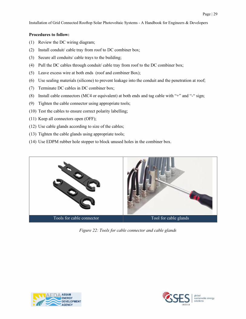
Tools for cable connector Tool for cable glands
Figure 22: Tools for cable connector and cable glands
Installation of Grid Connected Rooftop Solar Photovoltaic Systems - A Handbook for Engineers & Developers
Page | 30
2.7 Step 7: AC cabling and installation of inverter
When DC cables and DC combiner boxes are installed; the next step is to install AC cables and the inverter. Ensure that total voltage drop in all AC cables is less than 2% according to IEC 62548. Voltage drop in AC cables can be calculated using the formulas below: For AC cables in single-phase circuit:
Where, HSJJKLMN= Route length of AC cable in metres (Multiply by 2 for total circuit wire length) OSJ= Current in amperes ρ = resistivity of the wire in Ω/m/mm2 T/0U = Power factor PSJJKLMN = Cross section area (CSA) of cable in mm2
For AC cables in three-phase circuit:
QIVWX(SJ)(Q) = √3×HSJJKLMN × OSJ × Z × cosΦ
PSJJKLMN
Procedures to follow:
(1) Install the conduit/ cable tray;
(2) Pull the conductors through conduit or cable tray;
(3) Leave excess conductor or cable near each equipment terminal;
(4) Read inverter installation and operation manual carefully;
(5) Ensure that there is adequate ventilation for the inverter;
(6) Ensure that no direct sunlight falls on the inverter;
(7) Mount the inverter with accessories provided by the manufacturer;
(8) Ensure there is no grid supply to the inverter;
(9) Complete the installation from the inverter to the AC isolator and energy meter as per the drawing;
(10) Install the earthing connection as per inverter installation manual;
(11) Tighten the cable glands using appropriate tools.
!!"#!!"(!) =2!!!!!" !!"#$% !!!!!" !!!!!!! !"#!
!!" !!"#$%
Installation of Grid Connected Rooftop Solar Photovoltaic Systems - A Handbook for Engineers & Developers
Page | 31
Important to Note:
Adequate clearances between inverter and other objects have to be maintained for ventilation/ cooling of inverter. Generally instruction is given in the manufacturer’s installation manual.
In general,
• Minimum 20cm clearance to be maintained to the top and bottom of the inverter; • Minimum 10cm clearance to be maintained to the right and left of the inverter; • Keep adequate clearance to access the fans and air filters for regular cleaning; • Keep adequate clearance for cable entry.
Installation of Grid Connected Rooftop Solar Photovoltaic Systems - A Handbook for Engineers & Developers
Page | 32
2.8 Step 8: System protection and safety
(1) Earthing system configurations
Internationally, earthing systems are classified as TN System, TT System and IT System. TN system - has one or more points of the source of energy directly earthed and the exposed and extraneous conductive parts of the consumer side installation are connected by means of protective conductors to the earthed point(s) of the source, that is, there is a metallic path for earth fault currents to flow from the installation to the earthed point(s) of the source. TN systems are further sub-divided into TN-C, TN-S and TN-C-S systems. TT system - has one or more points of the source of energy directly earthed and the exposed and extraneous conductive parts of the installation are connected to a local earth electrode or electrodes are electrically independent of the source earth(s). IT system - has the source either unearthed or earthed through a high impedance and the exposed conductive parts of the installation are connected to electrically independent earth electrodes. In accordance to IS 3043: Code of Practice for Earthing, Indian distribution system uses an admixture of earthing types mentioned above. Different earthing systems for distribution network and corresponding earthing system for grid connected PV systems connected to the grid network have been discussed below.
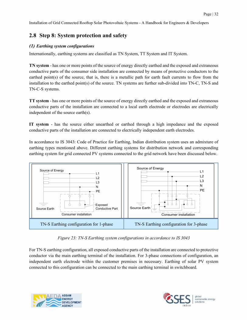
TN-S Earthing configuration for 1-phase TN-S Earthing configuration for 3-phase
Figure 23: TN-S Earthing system configurations in accordance to IS 3043
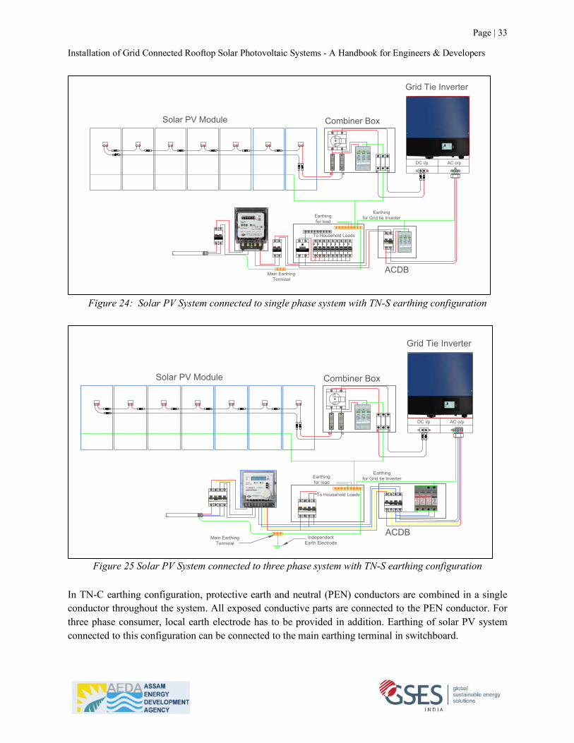
For TN-S earthing configuration, all exposed conductive parts of the installation are connected to protective conductor via the main earthing terminal of the installation. For 3-phase connections of configuration, an independent earth electrode within the customer premises in necessary. Earthing of solar PV system connected to this configuration can be connected to the main earthing terminal in switchboard.
L1L2L3NPE
Source Earth
Consumer installation
Source of Energy
ExposedConductive Part
L1L2L3NPE
Consumer installation
Source of Energy
Source Earth
Installation of Grid Connected Rooftop Solar Photovoltaic Systems - A Handbook for Engineers & Developers
Page | 33
Figure 24: Solar PV System connected to single phase system with TN-S earthing configuration
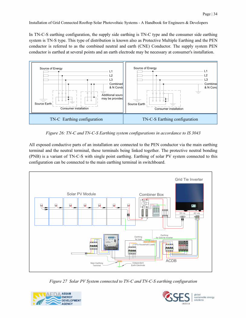
Figure 25 Solar PV System connected to three phase system with TN-S earthing configuration
In TN-C earthing configuration, protective earth and neutral (PEN) conductors are combined in a single conductor throughout the system. All exposed conductive parts are connected to the PEN conductor. For three phase consumer, local earth electrode has to be provided in addition. Earthing of solar PV system connected to this configuration can be connected to the main earthing terminal in switchboard.
Solar PV Module Combiner Box
Grid Tie Inverter
ACDB
PN
E
DC i/p AC o/p
To Household Loads
Earthingfor load
Main EarthingTerminal
Earthingfor Grid tie Inverter
TN -S Earthing (240V Single Phase
Solar PV Module Combiner Box
Grid Tie Inverter
ACDB
L1PE
DC i/p AC o/p
To Household Loads
Earthingfor load
Main EarthingTerminal
Earthingfor Grid tie Inverter
IndependentEarth Electrode
L2L3N
Installation of Grid Connected Rooftop Solar Photovoltaic Systems - A Handbook for Engineers & Developers
Page | 34
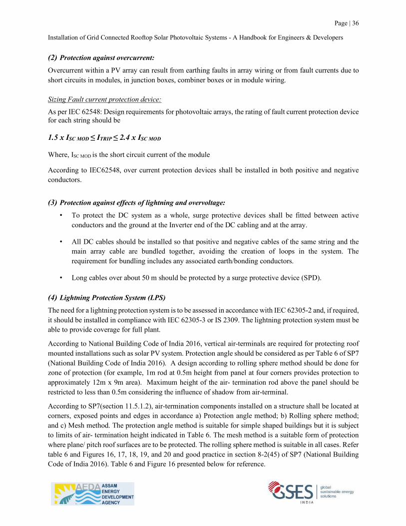
In TN-C-S earthing configuration, the supply side earthing is TN-C type and the consumer side earthing system is TN-S type. This type of distribution is known also as Protective Multiple Earthing and the PEN conductor is referred to as the combined neutral and earth (CNE) Conductor. The supply system PEN conductor is earthed at several points and an earth electrode may be necessary at consumer's installation.
TN-C Earthing configuration TN-C-S Earthing configuration
Figure 26: TN-C and TN-C-S Earthing system configurations in accordance to IS 3043
All exposed conductive parts of an installation are connected to the PEN conductor via the main earthing terminal and the neutral terminal, these terminals being linked together. The protective neutral bonding (PNB) is a variant of TN-C-S with single point earthing. Earthing of solar PV system connected to this configuration can be connected to the main earthing terminal in switchboard.
Figure 27 Solar PV System connected to TN-C and TN-C-S earthing configuration
L1L2L3Combined PE& N Conductor
Consumer installation
Source of Energy
Additional source earthmay be provided
Source Earth
L3Combined PE& N Conductor
Consumer installation
Source of EnergyL1L2
Source Earth
Solar PV Module Combiner Box
Grid Tie Inverter
ACDB
L1PE
DC i/p AC o/p
To Household Loads
Earthingfor load
Main EarthingTerminal
Earthingfor Grid tie Inverter
IndependentEarth Electrode
L2L3N

Installation of Grid Connected Rooftop Solar Photovoltaic Systems - A Handbook for Engineers & Developers
Page | 35
TT Earthing configuration IT Earthing configuration
Figure 28: TT and IT Earthing system configurations in accordance to IS 3043 In TT earthing configuration, all exposed conductive parts of the installation are connected to an earth electrode which is electrically independent of the source earthing system. Solar PV system connected to this configuration requires separate earthing for DC and AC side as shown in the figure below. In IT earthing configuration, all exposed conductive parts of an installation are connected to an earth electrode. The source is either connected to earth through a deliberately introduced earthing impedance or is isolated from earth. Solar PV system connected to TT and IT configuration requires separate earthing for DC and AC side as shown in the figure below.
Figure 29: Solar PV System connected to TT and IT earthing configuration
L1L2L3N
Consumer installation
Source of Energy
Source Earth
L1L2L3
Consumer installation
Source of Energy
IT- Earthing System
Earth
ing
Impe
ndan
ce
Solar PV Module Combiner Box
Grid Tie Inverter
ACDB
L1PE
DC i/p AC o/p
To Household Loads
Earthingfor load
Main EarthingTerminal
Earthingfor Grid tie Inverter
IndependentEarth Electrode
L2L3N
Independent DC SideEarth Electrode
Source Earth
Installation of Grid Connected Rooftop Solar Photovoltaic Systems - A Handbook for Engineers & Developers
Page | 36
(2) Protection against overcurrent:
Overcurrent within a PV array can result from earthing faults in array wiring or from fault currents due to short circuits in modules, in junction boxes, combiner boxes or in module wiring. Sizing Fault current protection device:
As per IEC 62548: Design requirements for photovoltaic arrays, the rating of fault current protection device for each string should be 1.5 x ISC MOD ≤ ITRIP ≤ 2.4 x ISC MOD Where, ISC MOD is the short circuit current of the module
According to IEC62548, over current protection devices shall be installed in both positive and negative conductors.
(3) Protection against effects of lightning and overvoltage:
• To protect the DC system as a whole, surge protective devices shall be fitted between active conductors and the ground at the Inverter end of the DC cabling and at the array.
• All DC cables should be installed so that positive and negative cables of the same string and the main array cable are bundled together, avoiding the creation of loops in the system. The requirement for bundling includes any associated earth/bonding conductors.
• Long cables over about 50 m should be protected by a surge protective device (SPD).
(4) Lightning Protection System (LPS)
The need for a lightning protection system is to be assessed in accordance with IEC 62305-2 and, if required, it should be installed in compliance with IEC 62305-3 or IS 2309. The lightning protection system must be able to provide coverage for full plant.
According to National Building Code of India 2016, vertical air-terminals are required for protecting roof mounted installations such as solar PV system. Protection angle should be considered as per Table 6 of SP7 (National Building Code of India 2016). A design according to rolling sphere method should be done for zone of protection (for example, 1m rod at 0.5m height from panel at four corners provides protection to approximately 12m x 9m area). Maximum height of the air- termination rod above the panel should be restricted to less than 0.5m considering the influence of shadow from air-terminal.
According to SP7(section 11.5.1.2), air-termination components installed on a structure shall be located at corners, exposed points and edges in accordance a) Protection angle method; b) Rolling sphere method; and c) Mesh method. The protection angle method is suitable for simple shaped buildings but it is subject to limits of air- termination height indicated in Table 6. The mesh method is a suitable form of protection where plane/ pitch roof surfaces are to be protected. The rolling sphere method is suitable in all cases. Refer table 6 and Figures 16, 17, 18, 19, and 20 and good practice in section 8-2(45) of SP7 (National Building Code of India 2016). Table 6 and Figure 16 presented below for reference.

Installation of Grid Connected Rooftop Solar Photovoltaic Systems - A Handbook for Engineers & Developers
Page | 37
According to SP7 (National Building Code of India 2016) radioactive air- terminals shall not be allowed. Any other kind of air- terminal like dissipation system/ESE air-terminal/CSE air-terminal shall not be acceptable. Table 6 of SP7: Maximum Values of Mesh Size and Protection Angle Corresponding to the Class of LPS (Clause 11.5.1.2)
Sl. No.
Class of LPS
Mesh Size
Rolling sphere Radius
Protection angle with respect to height
m m 10m 20m 30m 45m 60m
i) I 5 x 5 20 45 23 Cannot be used
ii) II 10 x 10 30 54 38 23 Cannot be used
iii) III 15 x 15 45 62 48 36 23 Cannot be used
iv) IV 20 x 20 60 65 54 45 34 23
Figure 30: Protection angle method of air-termination design for different heights according to table 6 of SP7 (Source Figure 16 of SP7) H = Height of the building over the ground reference plane h1= Physical height of an air-termination rod h2 = Height of the air-termination rod over the ground (= h1 + H) a1= The protection angle corresponding to the air-termination height, h = h1, being the height above the roof surface to be measured (reference plane) a2= The protection angle corresponding to the height, h2 (= H+ h1)

Installation of Grid Connected Rooftop Solar Photovoltaic Systems - A Handbook for Engineers & Developers
Page | 38
(5) SelectionofSPDforSolarPVProjectsSchematic below shows positions of Surge Protection Devices (SPDs) in a grid connected PV system:
Figure 31: Positions of Surge Protection Devices (SPDs) in a PV system
With the help of schematic above and table below, type of surge protection devices should be selected.
Location PV Modules or
Combiner Boxes Inverter DC side Inverter AC side Main Board
LDC LAC Lightning rod
Criteria < 10 m > 10 m < 10 m > 10 m Yes No
Type of SPD No need Type 2 Type 2 No need Type 2 Type 1 Type 2 (6) Voltage rating of DC protection devices: All system protection devices must have a voltage rating of at least the PV Array Maximum Voltage of the system. The PV array will attain a maximum voltage at the lowest expected temperature at the installation site. Maximum VOC of string at lowest expected site temperature (PV Array Maximum Voltage) to be calculated using formula below:
_`abcdcefghijklbmn = _ ×efg@jpg × g. q. Where,
M = Number of modules (in a string) in series C.F. = Correction Factor (to be taken from below table) STC = Standard Test Conditions (25oC Cell temperature, 1000W/m2 irradiance)
SPD1
SPD2
SPD3
SPD4
DCCombiner
Box
ACCombiner
BoxMain LV
Switch Board
DCCombiner
Box
L DC L AC

Installation of Grid Connected Rooftop Solar Photovoltaic Systems - A Handbook for Engineers & Developers
Page | 39
Table 3: Voltage correction factors for crystalline silicon PV modules (IEC 62548)
Lowest expected operating temperature (°C) Correction Factor 24 to 20 1.02 19 to 15 1.04 14 to 10 1.06
9 to 5 1.08 4 to 0 1.10
-1 to -5 1.12 -6 to -10 1.14 -1 to -15 1.16
-16 to -20 1.18
Table 4: Minimum Voltage Rating of Array Isolators according to IEC62548
System Installation Min Voltage Rating per pole
Min Voltage Rating Overall
Non-earthed array with isolated inverter 0.5 x VMAX OC ARRAY
V OC ARRAY
Earthed array with isolated inverter V MAX OC ARRAY
2 x V MAX OC ARRAY
Non-earthed array with non-isolated inverter V MAX OC ARRAY
2 x V MAX OC ARRAY
For example, if open circuit voltage (Voc) of a PV module at STC is 42V and 10 modules are connected in a string and modules are installed at site where minimum ambient temperature goes up to 0oC, the actual string voltage will be 10 x 42 x1.10 = 462V. Therefore overall minimum voltage rating for array isolators will be 2 x 462 = 924V. (7) System Isolation:According to Central Electricity Authority (Technical Standards for connectivity of Distributed Generation Resources) Regulations, 2013 there should be a manually operating isolating switch between distributed generation resource and electric system, which shall meet the following requirements:
• Allow visible verification that separation has been established
• Indicators to show clearly closed and open position
• Be capable of readily accessible and be capable of being locked in open position
• May not be rated for load-break
• Be located at height of 2.44 m above ground level
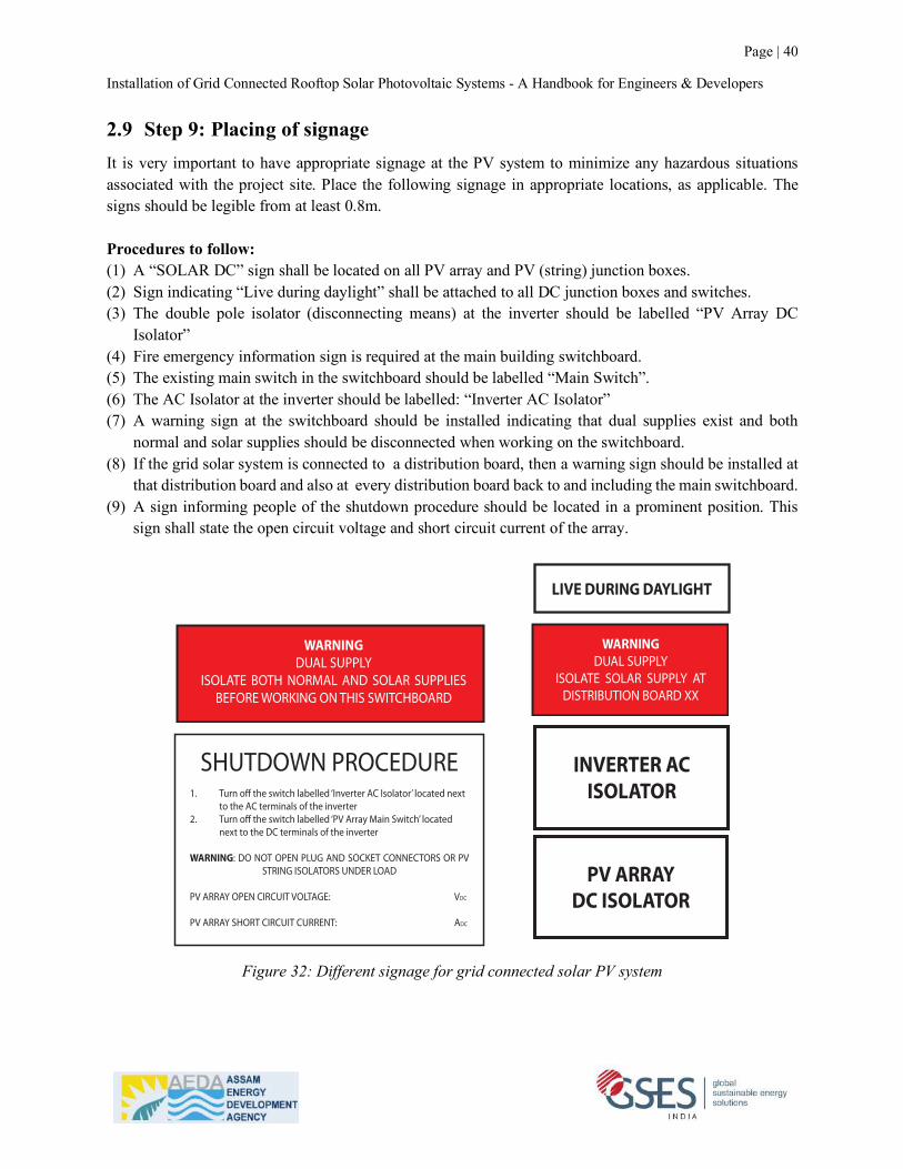
Installation of Grid Connected Rooftop Solar Photovoltaic Systems - A Handbook for Engineers & Developers
Page | 40
2.9 Step 9: Placing of signage It is very important to have appropriate signage at the PV system to minimize any hazardous situations associated with the project site. Place the following signage in appropriate locations, as applicable. The signs should be legible from at least 0.8m. Procedures to follow: (1) A “SOLAR DC” sign shall be located on all PV array and PV (string) junction boxes. (2) Sign indicating “Live during daylight” shall be attached to all DC junction boxes and switches. (3) The double pole isolator (disconnecting means) at the inverter should be labelled “PV Array DC
Isolator” (4) Fire emergency information sign is required at the main building switchboard. (5) The existing main switch in the switchboard should be labelled “Main Switch”. (6) The AC Isolator at the inverter should be labelled: “Inverter AC Isolator” (7) A warning sign at the switchboard should be installed indicating that dual supplies exist and both
normal and solar supplies should be disconnected when working on the switchboard. (8) If the grid solar system is connected to a distribution board, then a warning sign should be installed at
that distribution board and also at every distribution board back to and including the main switchboard. (9) A sign informing people of the shutdown procedure should be located in a prominent position. This
sign shall state the open circuit voltage and short circuit current of the array.
Figure 32: Different signage for grid connected solar PV system
Page | 201Chapter 16 - System Installation
Grid-Connected PV Systems Design and Installation© GSES Pty Ltd. ver. 1.1 India
Examples of signs are given in Appendix A of the standard. Some of the required ones are:t� A “SOLAR DC” sign shall be located on all PV array and PV string junction boxes.
SOLAR D.C
t� Sign indicating “Live during Daylight” shall be attached to all DC junction boxes and switches.
LIVE DURING DAYLIGHT
t� The double pole isolator at the inverter should be labelled “PV Array DC Isolator”
PV ARRAYMAIN SWITCH
PV ARRAYDC ISOLATOR
t� Fire emergency information sign required in the main building switchboard.The following signs are also recommended in addition to the ones required:
t� The existing main switch in the switchboard should be labelled “Main Switch (Normal Supply).
MAIN SWITCH(NORMALSUPPLY)
t� The A.C. Isolator at the inverter should be labelled: “Inverter A.C. Isolator”
INVERTER ACISOLATOR
t� A warning sign in the switchboard should be installed indicating that dual supplies exist and both normal and solar supplies should be disconnected when working on the switchboard.
WARNINGDUAL SUPPLY
ISOLATE BOTH NORMAL AND SOLAR SUPPLIES BEFORE WORKING ON THIS SWITCHBOARD
t� If the grid solar system is connected on a distribution board then a warning sign should be installed in that distribution board and also in every distribution board back to and including the main switchboard.
WARNINGDUAL SUPPLY
ISOLATE SOLAR SUPPLY AT DISTRIBUTION BOARD XX
t� A sign informing people of the shutdown procedure should be located in a prominent position. This shall state the open circuit voltage and short circuit current of the array.
Chapter 16 - System InstallationPage | 202
Grid-Connected PV Systems Design and Installation © GSES Pty Ltd. ver. 1.1 India
SHUTDOWN PROCEDURE1. Turn off the switch labelled ‘Inverter AC Isolator’ located next to the AC terminals of the inverter2. Turn off the switch labelled ‘PV Array Main Switch’ located next to the DC terminals of the inverter
WARNING: DO NOT OPEN PLUG AND SOCKET CONNECTORS OR PV STRING ISOLATORS UNDER LOAD
PV ARRAY OPEN CIRCUIT VOLTAGE: VDC
PV ARRAY SHORT CIRCUIT CURRENT: ADC
Page | 201Chapter 16 - System Installation
Grid-Connected PV Systems Design and Installation© GSES Pty Ltd. ver. 1.1 India
Examples of signs are given in Appendix A of the standard. Some of the required ones are:t� A “SOLAR DC” sign shall be located on all PV array and PV string junction boxes.
SOLAR D.C
t� Sign indicating “Live during Daylight” shall be attached to all DC junction boxes and switches.
LIVE DURING DAYLIGHT
t� The double pole isolator at the inverter should be labelled “PV Array DC Isolator”
PV ARRAYMAIN SWITCH
PV ARRAYDC ISOLATOR
t� Fire emergency information sign required in the main building switchboard.The following signs are also recommended in addition to the ones required:
t� The existing main switch in the switchboard should be labelled “Main Switch (Normal Supply).
MAIN SWITCH(NORMALSUPPLY)
t� The A.C. Isolator at the inverter should be labelled: “Inverter A.C. Isolator”
INVERTER ACISOLATOR
t� A warning sign in the switchboard should be installed indicating that dual supplies exist and both normal and solar supplies should be disconnected when working on the switchboard.
WARNINGDUAL SUPPLY
ISOLATE BOTH NORMAL AND SOLAR SUPPLIES BEFORE WORKING ON THIS SWITCHBOARD
t� If the grid solar system is connected on a distribution board then a warning sign should be installed in that distribution board and also in every distribution board back to and including the main switchboard.
WARNINGDUAL SUPPLY
ISOLATE SOLAR SUPPLY AT DISTRIBUTION BOARD XX
t� A sign informing people of the shutdown procedure should be located in a prominent position. This shall state the open circuit voltage and short circuit current of the array.
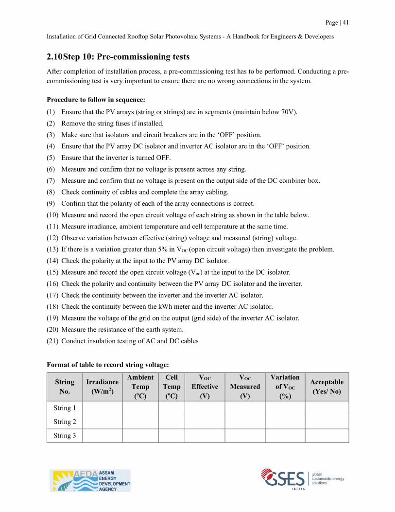
Installation of Grid Connected Rooftop Solar Photovoltaic Systems - A Handbook for Engineers & Developers
Page | 41
2.10 Step 10: Pre-commissioning tests After completion of installation process, a pre-commissioning test has to be performed. Conducting a pre-commissioning test is very important to ensure there are no wrong connections in the system. Procedure to follow in sequence:
(1) Ensure that the PV arrays (string or strings) are in segments (maintain below 70V). (2) Remove the string fuses if installed. (3) Make sure that isolators and circuit breakers are in the ‘OFF’ position. (4) Ensure that the PV array DC isolator and inverter AC isolator are in the ‘OFF’ position. (5) Ensure that the inverter is turned OFF. (6) Measure and confirm that no voltage is present across any string. (7) Measure and confirm that no voltage is present on the output side of the DC combiner box. (8) Check continuity of cables and complete the array cabling. (9) Confirm that the polarity of each of the array connections is correct. (10) Measure and record the open circuit voltage of each string as shown in the table below. (11) Measure irradiance, ambient temperature and cell temperature at the same time. (12) Observe variation between effective (string) voltage and measured (string) voltage. (13) If there is a variation greater than 5% in VOC (open circuit voltage) then investigate the problem. (14) Check the polarity at the input to the PV array DC isolator. (15) Measure and record the open circuit voltage (Voc) at the input to the DC isolator. (16) Check the polarity and continuity between the PV array DC isolator and the inverter. (17) Check the continuity between the inverter and the inverter AC isolator. (18) Check the continuity between the kWh meter and the inverter AC isolator. (19) Measure the voltage of the grid on the output (grid side) of the inverter AC isolator. (20) Measure the resistance of the earth system. (21) Conduct insulation testing of AC and DC cables
Format of table to record string voltage:
String No.
Irradiance (W/m2)
Ambient Temp (oC)
Cell Temp (oC)
VOC Effective
(V)
VOC
Measured (V)
Variation of VOC
(%)
Acceptable (Yes/ No)
String 1
String 2
String 3

Installation of Grid Connected Rooftop Solar Photovoltaic Systems - A Handbook for Engineers & Developers
Page | 42
Format of table to record insulation test results:
Nominal Voltage Rating of Cable / Conductor
(V)
Minimum Insulation resistance DC test Voltage
(V)
Recommended Minimum Insulation Resistance
(Mega Ohms)
250 500 25
600 1000 100
1000 1000 100
5000 2500 1000
15000 2500 5000
Source: (International) National Electrical Testing Association (NETA).

Installation of Grid Connected Rooftop Solar Photovoltaic Systems - A Handbook for Engineers & Developers
Page | 43
2.11 Step 11: Commissioning the system
When you are sure that the conductors and connections are acceptable and the system has successfully passed the pre-commissioning testing, then it’s time to commission the system. Procedures to follow in sequence:
(1) Refer to the inverter’s system manual and follow the start-up procedure
(2) Check the inverter display and confirm that the solar array is supplying power to the utility grid.
(3) Measure either the AC or DC current using a clamp meter and compare inverter output
(4) Measure the DC input voltage and confirm that it is within the operating limits of the inverter
(5) Measure the AC output voltage out of the inverter.
Format for recording information:
Time Irradiance (W/m2)
Ambient Temp (oC)
Cell Temp (oC)
VMP Measured
(V)
IMP
Measured (A)
PMP
(VMP x IMP) (W)
AC Power in Inverter display
(W)
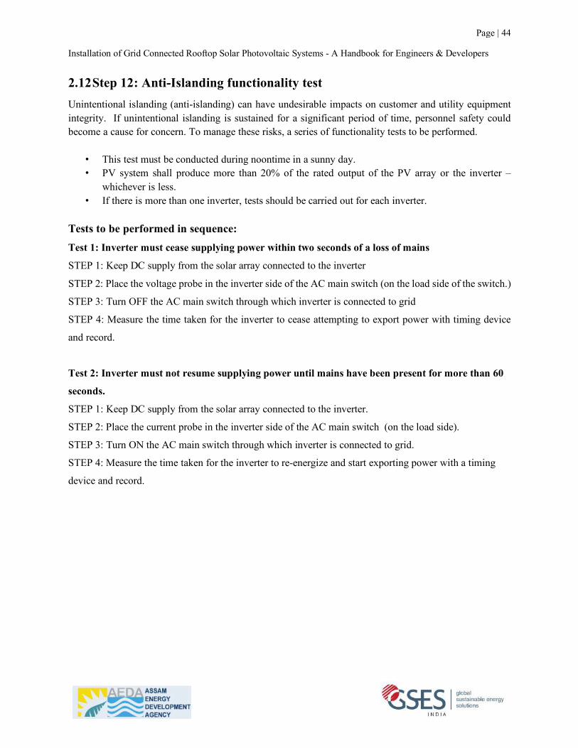
Installation of Grid Connected Rooftop Solar Photovoltaic Systems - A Handbook for Engineers & Developers
Page | 44
2.12 Step 12: Anti-Islanding functionality test Unintentional islanding (anti-islanding) can have undesirable impacts on customer and utility equipment integrity. If unintentional islanding is sustained for a significant period of time, personnel safety could become a cause for concern. To manage these risks, a series of functionality tests to be performed.
• This test must be conducted during noontime in a sunny day. • PV system shall produce more than 20% of the rated output of the PV array or the inverter –
whichever is less. • If there is more than one inverter, tests should be carried out for each inverter.
Tests to be performed in sequence: Test 1: Inverter must cease supplying power within two seconds of a loss of mains
STEP 1: Keep DC supply from the solar array connected to the inverter
STEP 2: Place the voltage probe in the inverter side of the AC main switch (on the load side of the switch.)
STEP 3: Turn OFF the AC main switch through which inverter is connected to grid
STEP 4: Measure the time taken for the inverter to cease attempting to export power with timing device
and record.
Test 2: Inverter must not resume supplying power until mains have been present for more than 60
seconds.
STEP 1: Keep DC supply from the solar array connected to the inverter.
STEP 2: Place the current probe in the inverter side of the AC main switch (on the load side).
STEP 3: Turn ON the AC main switch through which inverter is connected to grid.
STEP 4: Measure the time taken for the inverter to re-energize and start exporting power with a timing
device and record.
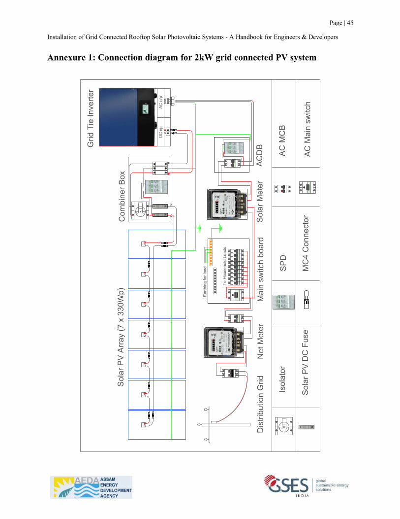
Installation of Grid Connected Rooftop Solar Photovoltaic Systems - A Handbook for Engineers & Developers
Page | 45
Annexure 1: Connection diagram for 2kW grid connected PV system
To H
ouse
hold
Loa
ds
Sola
r PV
Arra
y (7
x 3
30W
p)C
ombi
ner B
ox
Grid
Tie
Inve
rter
ACD
BM
ain
switc
h bo
ard
Sola
r Met
erN
et M
eter
Dis
tribu
tion
Grid
LN
PE
DC
i/p
AC o
/p
Isol
ator
Sola
r PV
DC
Fus
e
SPD
MC
4 C
onne
ctor
AC M
CB
AC M
ain
switc
h
Earth
ing
for l
oad
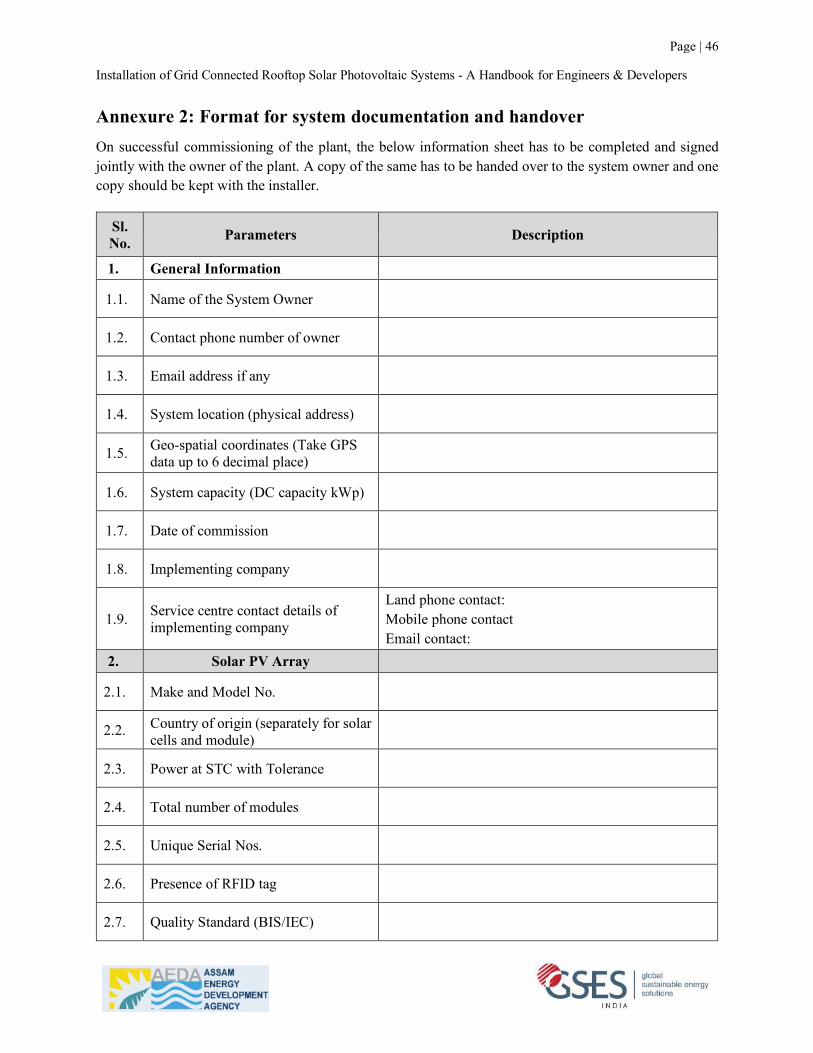
Installation of Grid Connected Rooftop Solar Photovoltaic Systems - A Handbook for Engineers & Developers
Page | 46
Annexure 2: Format for system documentation and handover On successful commissioning of the plant, the below information sheet has to be completed and signed jointly with the owner of the plant. A copy of the same has to be handed over to the system owner and one copy should be kept with the installer.
Sl. No. Parameters Description
1. General Information
1.1. Name of the System Owner
1.2. Contact phone number of owner
1.3. Email address if any
1.4. System location (physical address)
1.5. Geo-spatial coordinates (Take GPS data up to 6 decimal place)
1.6. System capacity (DC capacity kWp)
1.7. Date of commission
1.8. Implementing company
1.9. Service centre contact details of implementing company
Land phone contact: Mobile phone contact Email contact:
2. Solar PV Array
2.1. Make and Model No.
2.2. Country of origin (separately for solar cells and module)
2.3. Power at STC with Tolerance
2.4. Total number of modules
2.5. Unique Serial Nos.
2.6. Presence of RFID tag
2.7. Quality Standard (BIS/IEC)
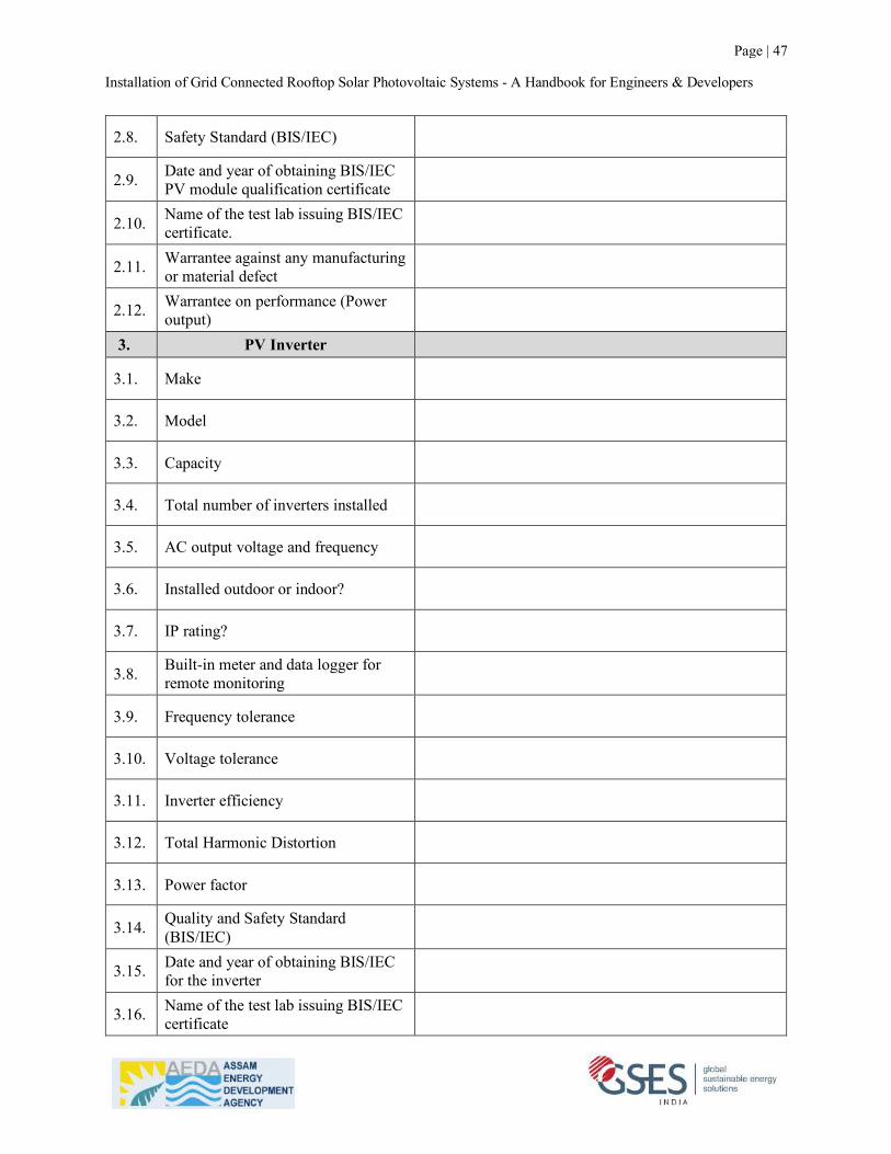
Installation of Grid Connected Rooftop Solar Photovoltaic Systems - A Handbook for Engineers & Developers
Page | 47
2.8. Safety Standard (BIS/IEC)
2.9. Date and year of obtaining BIS/IEC PV module qualification certificate
2.10. Name of the test lab issuing BIS/IEC certificate.
2.11. Warrantee against any manufacturing or material defect
2.12. Warrantee on performance (Power output)
3. PV Inverter
3.1. Make
3.2. Model
3.3. Capacity
3.4. Total number of inverters installed
3.5. AC output voltage and frequency
3.6. Installed outdoor or indoor?
3.7. IP rating?
3.8. Built-in meter and data logger for remote monitoring
3.9. Frequency tolerance
3.10. Voltage tolerance
3.11. Inverter efficiency
3.12. Total Harmonic Distortion
3.13. Power factor
3.14. Quality and Safety Standard (BIS/IEC)
3.15. Date and year of obtaining BIS/IEC for the inverter
3.16. Name of the test lab issuing BIS/IEC certificate

Installation of Grid Connected Rooftop Solar Photovoltaic Systems - A Handbook for Engineers & Developers
Page | 48
3.17. Warrantee against any manufacturing defect and violation of conformity of regulatory requirement
4. Array Structure
4.1. Type of structure used
4.2. Material of structure
4.3. Frame size and orientation (Portrait / landscape)
4.4. Thickness of structure materials
4.5. Type of coating
4.6. Type of grouting to RCC roof and size of PCC block if used
4.7. Material of fasteners (nuts, bolts, clamps, hooks etc.)
4.8. Tilt angle
4.9.
Are the modules are installed facing true south? If not which orientation and angle of deviation from true south.
4.10. Clearance of lowest part of structure to the roof in mm
5. DC String Combiner Box
5.1. Make
5.2. Materials and IP rating
5.3. Rating of DC fuses if used
5.4. Rating of DC isolators
5.5. Type of and SPDs used
5.6. Have you marked cable ferrules for polarity identification?
5.7. Have you used one cable gland for one cable?
5.8. Have you tightened the cable glands properly?
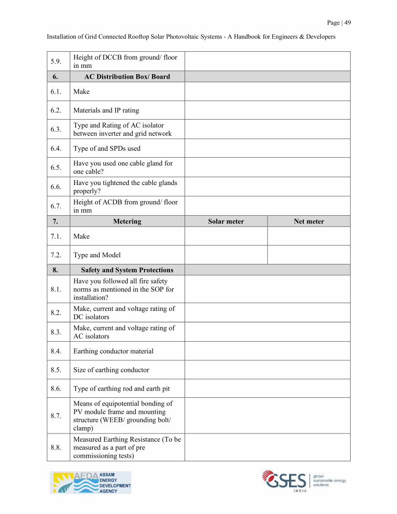
Installation of Grid Connected Rooftop Solar Photovoltaic Systems - A Handbook for Engineers & Developers
Page | 49
5.9. Height of DCCB from ground/ floor in mm
6. AC Distribution Box/ Board
6.1. Make
6.2. Materials and IP rating
6.3. Type and Rating of AC isolator between inverter and grid network
6.4. Type of and SPDs used
6.5. Have you used one cable gland for one cable?
6.6. Have you tightened the cable glands properly?
6.7. Height of ACDB from ground/ floor in mm
7. Metering Solar meter Net meter
7.1. Make
7.2. Type and Model
8. Safety and System Protections
8.1. Have you followed all fire safety norms as mentioned in the SOP for installation?
8.2. Make, current and voltage rating of DC isolators
8.3. Make, current and voltage rating of AC isolators
8.4. Earthing conductor material
8.5. Size of earthing conductor
8.6. Type of earthing rod and earth pit
8.7.
Means of equipotential bonding of PV module frame and mounting structure (WEEB/ grounding bolt/ clamp)
8.8. Measured Earthing Resistance (To be measured as a part of pre commissioning tests)
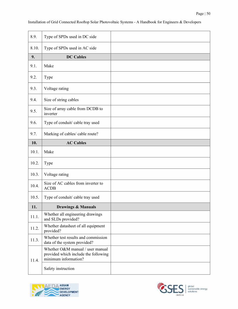
Installation of Grid Connected Rooftop Solar Photovoltaic Systems - A Handbook for Engineers & Developers
Page | 50
8.9. Type of SPDs used in DC side
8.10. Type of SPDs used in AC side
9. DC Cables
9.1. Make
9.2. Type
9.3. Voltage rating
9.4. Size of string cables
9.5. Size of array cable from DCDB to inverter
9.6. Type of conduit/ cable tray used
9.7. Marking of cables/ cable route?
10. AC Cables
10.1. Make
10.2. Type
10.3. Voltage rating
10.4. Size of AC cables from inverter to ACDB
10.5. Type of conduit/ cable tray used
11. Drawings & Manuals
11.1. Whether all engineering drawings and SLDs provided?
11.2. Whether datasheet of all equipment provided?
11.3. Whether test results and commission data of the system provided?
11.4.
Whether O&M manual / user manual provided which include the following minimum information?
Safety instruction
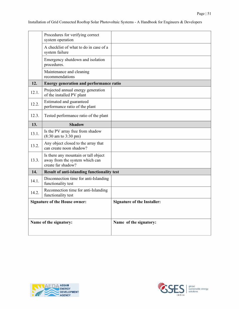
Installation of Grid Connected Rooftop Solar Photovoltaic Systems - A Handbook for Engineers & Developers
Page | 51
Procedures for verifying correct system operation
A checklist of what to do in case of a system failure
Emergency shutdown and isolation procedures.
Maintenance and cleaning recommendations
12. Energy generation and performance ratio
12.1. Projected annual energy generation of the installed PV plant
12.2. Estimated and guaranteed performance ratio of the plant
12.3. Tested performance ratio of the plant
13. Shadow
13.1. Is the PV array free from shadow (8:30 am to 3:30 pm)
13.2. Any object closed to the array that can create noon shadow?
13.3. Is there any mountain or tall object away from the system which can create far shadow?
14. Result of anti-islanding functionality test
14.1. Disconnection time for anti-Islanding functionality test
14.2. Reconnection time for anti-Islanding functionality test
Signature of the House owner: Signature of the Installer:
Name of the signatory: Name of the signatory:

Standard Operating Procedure for Installation of Grid Connected Rooftop Solar Photovoltaic Systems
- A Handbook for Engineers & Developers
GSES Contact: GSES India Sustainable Energy Pvt. Ltd. F – 7B, Okhla Industrial Area Phase 1 New Delhi - 110020, India Phone: +91 - 11 - 41040534 Email: [email protected] Web: www.gses.in
About SUPRABHA
The Sustainable Partnership for Rooftop Solar Acceleration in Bharat (SUPRABHA) is a USD13 million program which is led by The World Bank and SBI and implemented in partnership with the Ministry of New and Renewable Energy (MNRE). SUPRABHA will be offering Technical Assistance to 17 Partner States (Assam, Andhra Pradesh, Bihar, Chhattisgarh, Chandigarh, Delhi, Haryana, Jharkhand, Madhya Pradesh, Manipur, Meghalaya, Mizoram, Nagaland, Odisha, Rajasthan, Sikkim and Tripura) towards establishing an enabling ecosystem for accelerated deployment of grid connected Rooftop Solar. The consortium partners to implement SUPRABHA are EY, GSES, Edelman, EVI, IDAM and SCGJ. EY is the lead partner. The SUPRABHA TA Program consists of six interventions namely Policy, Capacity Building, SSN Knowledge Exchange, Media and Outreach, Process Streamlining and Demand Aggregation. The program covers a wide range of stakeholders from consumers, regulators and distribution companies to urban local bodies, financial institutions and entrepreneurs.
About GSES
GSES India Sustainable Energy Pvt. Ltd. is the Indian counterpart of Global Sustainable Energy Solutions (GSES), Australia a multi-disciplinary organisation specialising in professional services and training across the Renewable Energies sector and comprises a team of highly experienced systems engineers, designers and installers and accredited trainers. GSES is recognised within industry as the leader in renewable energy innovation and technology education. GSES develops and delivers solar PV training courses in accordance with international competency standards and accreditation requirements. Internationally, GSES undertake to guarantee the quality of all its training programs. GSES has authored a library of publications, including solar training books, solar reference books and solar business and marketing books. All books are updated regularly to ensure students and readers are presented with the most recent information available on renewable energy technology.
The World Bank Contact: Dr. Amit Jain Renewable Energy Specialist Email: [email protected]