griffco valve inc. g-series back pressure valves pressure...
TRANSCRIPT
Griffco Valve Inc. 6010 N. Bailey Ave., Ste 1B Amherst, NY 14226 Phone: 1 716 835-0891 Fax: 1 716 835-0893
G - SERIESPRESSURE RELIEF VALVE
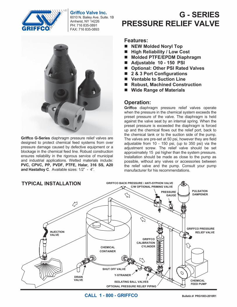
Griffco G-Series diaphragm pressure relief valves are designed to protect chemical feed systems from over pressure damage caused by defective equipment or a blockage in the chemical feed line. Robust construction ensures reliability in the rigorous service of municipal and industrial applications. Wetted materials include: PVC, CPVC, PP, PVDF, PTFE, Halar, 316 SS, A20 and Hastalloy C. Available sizes: 1/2” - 4”.
Features: NEW Molded Noryl Top High Reliability / Low Cost Molded PTFE/EPDM Diaphragm Adjustable 10 - 150 PSI Optional: Other PSI Rated Valves 2 & 3 Port Configurations Ventable to Suction Line Robust, Machined Construction Wide Range of Materials
Operation: Griffco diaphragm pressure relief valves operate when the pressure in the chemical system exceeds the preset pressure of the valve. The diaphragm is held against the valve seat by an internal spring. When the preset pressure is exceeded the diaphragm is forced up and the chemical flows out the relief port, back to the chemical tank or to the suction side of the pump. The valves are pre-set at 50 psi, however they are field adjustable from 10 - 150 psi, (up to 350 psi) via the adjustment screw. The relief valve should be set approximately 15 psi higher than the system pressure. Installation should be made as close to the pump as possible, without any valves or accessories between the relief valve and the pump. Consult your pump manufacturer for his recommendations.
INJECTIONVALVE
DRAINVALVE
SHUT OFF VALVE
Y-STRAINER
ISOLATING BALL VALVESOPTIONAL PRESSURE RELIEF PIPING
CHEMICALCONTAINER
GRIFFCOCALIBRATION
CYLINDER
GRIFFCO PRESSURERELIEF VALVE
CHEMICALFEED PUMP
PULSATIONDAMPENER
GRIFFCO BACK PRESSURE / ANTI-SYPHON VALVEC/W OPTIONAL PRIMING VALVE
PRESSUREGAUGE
TYPICAL INSTALLATION
CALL 1 - 800 - GRIFFCO Bulletin # PRG1003-2010R1
Griffco Valve Inc. 6010 N. Bailey Ave. Suite. 1B Amherst, NY 14226 PH: 716 835-0891 FAX: 716 835-0893
G-SERIESBACK PRESSURE VALVES
Griffco G-Series diaphragm back pressure valves are designed to enhance the performance of chemical feed systems by applying a continuous back pressure to the chemical feed pump, while also acting as an anti-syphon valve. Robust construction ensures reliability in the rigorous service of municipal and industrial applications. Wetted materials include: PVC, CPVC, PP, PVDF, PTFE, Halar, 316 SS, A20 and Hast. C. Available sizes: 1/2” - 4”.
Features: NEW Molded Noryl Top High Reliability / Low Cost Molded PTFE/EPDM Diaphragm Adjustable 10 - 150 PSI Optional PSI Rated Valves Anti-Syphon Function Robust, Machined Construction Tamper Resistant Adjustment Screw Wide Range of Materials
Operation: Griffco diaphragm back pressure valves apply positive discharge pressure to a metering pump system to prevent siphoning and eliminate varying dosage rates caused by fluctuating downstream pressure. The diaphragm is held against the valve seat by an internal spring. When the preset pressure is exceeded, the diaphragm is forced up and chemical flows through the valve to the injection point. The valves are preset for 50 psi, however they are field adjustable from 10 - 150 psi via the adjustment screw. Installation should be as close to the injection point as possible to prevent chemical line drainage, and it is most important that all chemical system equipment such as pulsation dampeners and pressure gauges are between the pump and back pressure valve.
INJECTIONVALVE
DRAINVALVE
SHUT OFF VALVE
Y-STRAINER
ISOLATING BALL VALVESOPTIONAL PRESSURE RELIEF PIPING
CHEMICALCONTAINER
GRIFFCOCALIBRATION
CYLINDER
GRIFFCO PRESSURERELIEF VALVE
CHEMICALFEED PUMP
PULSATIONDAMPENER
GRIFFCO BACK PRESSURE / ANTI-SYPHON VALVEC/W OPTIONAL PRIMING VALVE
PRESSUREGAUGE
TYPICAL INSTALLATION
CALL 1 - 800 - GRIFFCO Bulletin # BPG1003-2010R1

Technical Data: Model PRG Sizes: 1/2”, 3/4”, 1”, 1 1/2”, 2”, 3”, 4”
Connections: NPT, Socket, Union, & Flange
Pressure Adjustment Standard: 10 - 150 psi, Optional: 0 - 50 psi, 10 - 250 psi, 50 - 350 psi
*Note: Size 1 1/2" and larger PRG valves 10 – 250 psi Max range ONLY.
Flow Rates @ 150 psi Shipping Weight: lbs
Size Pulsating Continuous Plastic Metal / Plastic Top Metal / Metal Top
1/2” 3/4” 1” 1 1/2” 2” 3” 4”
300 USgph 300 USgph 500 USgph 1200 USgph 2350 USgph 5200 USgph 5200 USgph
21 USgpm 21 USgpm 26 USgpm 63 USgpm 120 USgpm 270 USgpm 270 USgpm
3.0 3.0 3.5 7.0 9.0 28.0 30.0
5.5 5.5 6.0 14.0 20.0
6.5 7.0 7.0 23.0 30.0
Max Temperature: (°F) PVC: 140° ; CPVC & PP: 195°; PTFE, PVDF, & Metal: 300°, (Peak 390°)
Max Operating Pressure (psi) @ 70 deg. F Plastic/Noryl: 375 psi Metal/Metal: 2000 psi
Materials of Construction:
Diaphragm PTFE / EPDM, Optional: Viton, Hypalon, & PTFE / Viton
Valve Top Standard: Noryl (1/2” – 2”) PVC (3” & 4”) Optional: 316 SS
Valve Body PVC, CPVC, PP, PTFE, PVDF, Halar, 316 SS, A 20, Hast. C
Performance Curves: (3” & 4” curves on request)
Product Codes For Ordering Pressure Relief Valves:
PRG □□□ □ □ □ 1 2 3 4 1 = Size 2 = Material 3 = Spring Opt 4 = Options 050 - 1/2” P - PVC 1 - 0 - 50 psi V - Viton Diaphragm 075 - 3/4” CP - CPVC 2 - 10 - 250 psi S - Socket Connection 100 - 1” PP - Polypro F - Flange Connection 155 - 1 1/2” T - PTFE U - Union Connection 200 - 2” K - PVDF B - BSP Connections 300 - 3” H - Halar OSS - 316 SS Top 400 - 4” S - 316 SS MSS - 50 - 350 psi A - Alloy 20 AR - Priming Valve C - Hastalloy C 90 - 90° Configuration
Dimensions:
DIMENSIONS: PRG-SERIES
All Materials
A ︵in ︶ B ︵in ︶ C ︵in ︶Size1/2"3/4"1"
5.5605.5605.860
3.5003.5003.500
1.1251.1251.250
4.9008.350 1.8254.9008.900 2.1502"
1 1
2"
NOTE: 11
2"& 2"
VALVES
DO
NOT
HAVE
BOTTOM
PORT
0
250
500
750
1000
1250
1500
1750
2000
2250
2500
0 20 40 60 80 100 120 140Pressure Drop - PSI
Puls
atin
g Fl
ow -
USG
PH
2”
1 1/2”
1” ¾”½”
Email: [email protected] Website: www.griffcovalve.com
Note: For Optional 2-Port pressure relief valve put “2” after PRGNote: Option MSS is only for use on 316SS, A20, & Hast C. Valves.
M-SERIES PRESSURE RELIEF VALVES
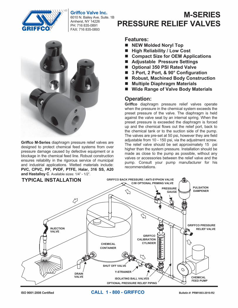
Griffco M-Series diaphragm pressure relief valves are designed to protect chemical feed systems from over pressure damage caused by defective equipment or a blockage in the chemical feed line. Robust construction ensures reliability in the rigorous service of municipal and industrial applications. Wetted materials include: PVC, CPVC, PP, PVDF, PTFE, Halar, 316 SS, A20 and Hastalloy C. Available sizes: 1/4” - 1/2”.
Features: NEW Molded Noryl Top High Reliability / Low Cost Compact Size for OEM Applications Adjustable Pressure Settings Optional 350 PSI Rated Valve 3 Port, 2 Port, & 90° Configuration Robust, Machined Body Construction Multiple Diaphragm Materials Wide Range of Valve Body Materials
Operation: Griffco diaphragm pressure relief valves operate when the pressure in the chemical system exceeds the preset pressure of the valve. The diaphragm is held against the valve seat by an internal spring. When the preset pressure is exceeded the diaphragm is forced up and the chemical flows out the relief port, back to the chemical tank or to the suction side of the pump. The valves are pre-set at 50 psi, however they are field adjustable from 10 - 150 psi, via the adjustment screw. The relief valve should be set approximately 15 psi higher than the system pressure. Installation should be made as close to the pump as possible, without any valves or accessories between the relief valve and the pump. Consult your pump manufacturer for his recommendations.
INJECTIONVALVE
DRAINVALVE
SHUT OFF VALVE
Y-STRAINER
ISOLATING BALL VALVESOPTIONAL PRESSURE RELIEF PIPING
CHEMICALCONTAINER
GRIFFCOCALIBRATION
CYLINDER
GRIFFCO PRESSURERELIEF VALVE
CHEMICALFEED PUMP
PULSATIONDAMPENER
GRIFFCO BACK PRESSURE / ANTI-SYPHON VALVEC/W OPTIONAL PRIMING VALVE
PRESSUREGAUGE
TYPICAL INSTALLATION
ISO 9001:2008 Certified CALL 1 - 800 - GRIFFCO Bulletin # PRM1003-2010-R2
Griffco Valve Inc. 6010 N. Bailey Ave. Suite. 1B Amherst, NY 14226 PH: 716 835-0891 FAX: 716 835-0893
G-SERIESBACK PRESSURE VALVES
Griffco G-Series diaphragm back pressure valves are designed to enhance the performance of chemical feed systems by applying a continuous back pressure to the chemical feed pump, while also acting as an anti-syphon valve. Robust construction ensures reliability in the rigorous service of municipal and industrial applications. Wetted materials include: PVC, CPVC, PP, PVDF, PTFE, Halar, 316 SS, A20 and Hast. C. Available sizes: 1/2” - 4”.
Features: NEW Molded Noryl Top High Reliability / Low Cost Molded PTFE/EPDM Diaphragm Adjustable 10 - 150 PSI Optional PSI Rated Valves Anti-Syphon Function Robust, Machined Construction Tamper Resistant Adjustment Screw Wide Range of Materials
Operation: Griffco diaphragm back pressure valves apply positive discharge pressure to a metering pump system to prevent siphoning and eliminate varying dosage rates caused by fluctuating downstream pressure. The diaphragm is held against the valve seat by an internal spring. When the preset pressure is exceeded, the diaphragm is forced up and chemical flows through the valve to the injection point. The valves are preset for 50 psi, however they are field adjustable from 10 - 150 psi via the adjustment screw. Installation should be as close to the injection point as possible to prevent chemical line drainage, and it is most important that all chemical system equipment such as pulsation dampeners and pressure gauges are between the pump and back pressure valve.
INJECTIONVALVE
DRAINVALVE
SHUT OFF VALVE
Y-STRAINER
ISOLATING BALL VALVESOPTIONAL PRESSURE RELIEF PIPING
CHEMICALCONTAINER
GRIFFCOCALIBRATION
CYLINDER
GRIFFCO PRESSURERELIEF VALVE
CHEMICALFEED PUMP
PULSATIONDAMPENER
GRIFFCO BACK PRESSURE / ANTI-SYPHON VALVEC/W OPTIONAL PRIMING VALVE
PRESSUREGAUGE
TYPICAL INSTALLATION
CALL 1 - 800 - GRIFFCO Bulletin # BPG1003-2010R1
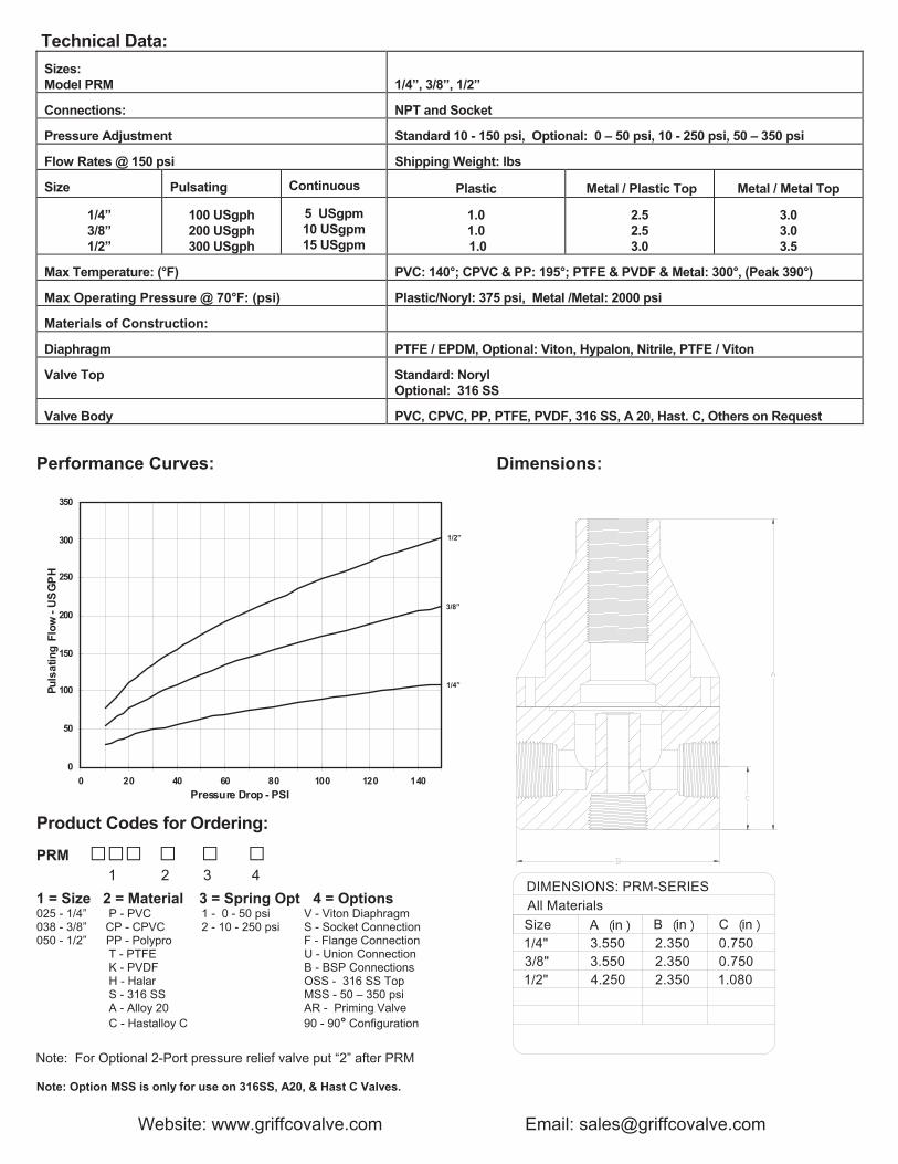
Technical Data: Sizes: Model PRM
1/4”, 3/8”, 1/2”
Connections: NPT and Socket
Pressure Adjustment Standard 10 - 150 psi, Optional: 0 – 50 psi, 10 - 250 psi, 50 – 350 psi
Flow Rates @ 150 psi Shipping Weight: lbs
Size Pulsating Continuous Plastic Metal / Plastic Top Metal / Metal Top
1/4” 3/8” 1/2”
100 USgph 200 USgph 300 USgph
5 USgpm 10 USgpm 15 USgpm
1.0 1.0 1.0
2.5 2.5 3.0
3.0 3.0 3.5
Max Temperature: (°F) PVC: 140°; CPVC & PP: 195°; PTFE & PVDF & Metal: 300°, (Peak 390°)
Max Operating Pressure @ 70°F: (psi) Plastic/Noryl: 375 psi, Metal /Metal: 2000 psi
Materials of Construction:
Diaphragm PTFE / EPDM, Optional: Viton, Hypalon, Nitrile, PTFE / Viton
Valve Top Standard: Noryl Optional: 316 SS
Valve Body PVC, CPVC, PP, PTFE, PVDF, 316 SS, A 20, Hast. C, Others on Request
Performance Curves:
0
50
100
150
200
250
300
350
0 20 40 60 80 100 120 140Pressure Drop - PSI
Puls
atin
g F
low
- U
SG
PH
Product Codes for Ordering:
PRM □□□ □ □ □ 1 2 3 4 1 = Size 2 = Material 3 = Spring Opt 4 = Options 025 - 1/4” P - PVC 1 - 0 - 50 psi V - Viton Diaphragm 038 - 3/8” CP - CPVC 2 - 10 - 250 psi S - Socket Connection 050 - 1/2” PP - Polypro F - Flange Connection T - PTFE U - Union Connection K - PVDF B - BSP Connections H - Halar OSS - 316 SS Top S - 316 SS MSS - 50 – 350 psi A - Alloy 20 AR - Priming Valve C - Hastalloy C 90 - 90° Configuration
Dimensions:
3/8"
DIMENSIONS: PRM-SERIES
All Materials
A ︵in ︶ B ︵in ︶ C ︵in ︶Size1/4" 3.550 2.350 0.750
3.550 2.350 0.7501/2" 4.250 2.350 1.080
1/2”
3/8”
1/4”
Note: Option MSS is only for use on 316SS, A20, & Hast C Valves.
Website: www.griffcovalve.com Email: [email protected]
Note: For Optional 2-Port pressure relief valve put “2” after PRM
Griffco Valve Inc. 6010 N. Bailey Ave, Ste 1B Amherst, NY 14226 Phone: 1 716 835-0891 Fax: 1 716 835-0893
HIGH FLOW SERIESPRESSURE RELIEF VALVES
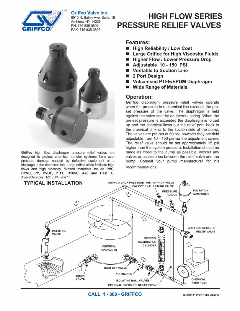
Griffco high flow diaphragm pressure relief valves are designed to protect chemical transfer systems from over pressure damage caused by defective equipment or a blockage in the chemical line. Large orifice sizes facilitate high flows and high viscosity. Wetted materials include PVC, CPVC, PP, PVDF, PTFE, 316SS, A20 and Hast. C. Available sizes: 1/2” , 3/4, and 1”.
Features: High Reliability / Low Cost Large Orifice for High Viscosity Fluids Higher Flow / Lower Pressure Drop Adjustable 10 - 150 PSI Ventable to Suction Line 2 Port Design Vulcanised PTFE/EPDM Diaphragm Wide Range of Materials
Operation: Griffco diaphragm pressure relief valves operate when the pressure in a chemical line exceeds the pre-set pressure of the valve. The diaphragm is held against the valve seat by an internal spring. When the pre-set pressure is exceeded the diaphragm is forced up and the chemical flows out the relief port, back to the chemical tank or to the suction side of the pump. The valves are pre-set at 50 psi, however they are field adjustable from 10 - 150 psi via the adjustment screw. The relief valve should be set approximately 15 psi higher than the system pressure. Installation should be made as close to the pump as possible, without any valves or accessories between the relief valve and the pump. Consult your pump manufacturer for his recommendations..
INJECTIONVALVE
DRAINVALVE
SHUT OFF VALVE
Y-STRAINER
ISOLATING BALL VALVESOPTIONAL PRESSURE RELIEF PIPING
CHEMICALCONTAINER
GRIFFCOCALIBRATION
CYLINDER
GRIFFCO PRESSURERELIEF VALVE
CHEMICALFEED PUMP
PULSATIONDAMPENER
GRIFFCO BACK PRESSURE / ANTI-SYPHON VALVEC/W OPTIONAL PRIMING VALVE
PRESSUREGAUGE
TYPICAL INSTALLATION
CALL 1 - 800 - GRIFFCO Bulletin # PRHF1005-2008R2
Griffco Valve Inc. 6010 N. Bailey Ave. Suite. 1B Amherst, NY 14226 PH: 716 835-0891 FAX: 716 835-0893
G-SERIESBACK PRESSURE VALVES
Griffco G-Series diaphragm back pressure valves are designed to enhance the performance of chemical feed systems by applying a continuous back pressure to the chemical feed pump, while also acting as an anti-syphon valve. Robust construction ensures reliability in the rigorous service of municipal and industrial applications. Wetted materials include: PVC, CPVC, PP, PVDF, PTFE, Halar, 316 SS, A20 and Hast. C. Available sizes: 1/2” - 4”.
Features: NEW Molded Noryl Top High Reliability / Low Cost Molded PTFE/EPDM Diaphragm Adjustable 10 - 150 PSI Optional PSI Rated Valves Anti-Syphon Function Robust, Machined Construction Tamper Resistant Adjustment Screw Wide Range of Materials
Operation: Griffco diaphragm back pressure valves apply positive discharge pressure to a metering pump system to prevent siphoning and eliminate varying dosage rates caused by fluctuating downstream pressure. The diaphragm is held against the valve seat by an internal spring. When the preset pressure is exceeded, the diaphragm is forced up and chemical flows through the valve to the injection point. The valves are preset for 50 psi, however they are field adjustable from 10 - 150 psi via the adjustment screw. Installation should be as close to the injection point as possible to prevent chemical line drainage, and it is most important that all chemical system equipment such as pulsation dampeners and pressure gauges are between the pump and back pressure valve.
INJECTIONVALVE
DRAINVALVE
SHUT OFF VALVE
Y-STRAINER
ISOLATING BALL VALVESOPTIONAL PRESSURE RELIEF PIPING
CHEMICALCONTAINER
GRIFFCOCALIBRATION
CYLINDER
GRIFFCO PRESSURERELIEF VALVE
CHEMICALFEED PUMP
PULSATIONDAMPENER
GRIFFCO BACK PRESSURE / ANTI-SYPHON VALVEC/W OPTIONAL PRIMING VALVE
PRESSUREGAUGE
TYPICAL INSTALLATION
CALL 1 - 800 - GRIFFCO Bulletin # BPG1003-2010R1
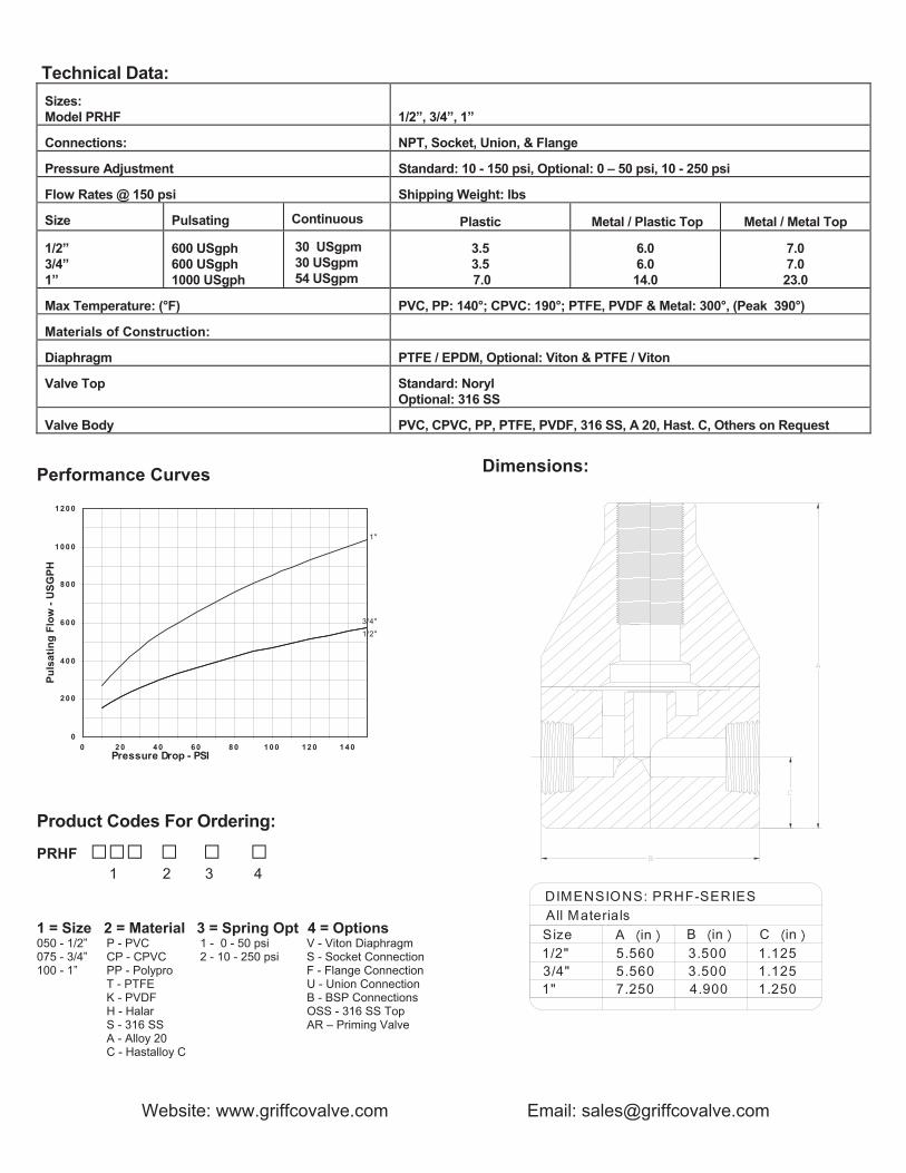
Technical Data: Sizes: Model PRHF
1/2”, 3/4”, 1”
Connections: NPT, Socket, Union, & Flange
Pressure Adjustment Standard: 10 - 150 psi, Optional: 0 – 50 psi, 10 - 250 psi
Flow Rates @ 150 psi Shipping Weight: lbs
Size Pulsating Continuous Plastic Metal / Plastic Top Metal / Metal Top
1/2” 3/4” 1”
600 USgph 600 USgph 1000 USgph
30 USgpm 30 USgpm 54 USgpm
3.5 3.5 7.0
6.0 6.0 14.0
7.0 7.0 23.0
Max Temperature: (°F) PVC, PP: 140°; CPVC: 190°; PTFE, PVDF & Metal: 300°, (Peak 390°)
Materials of Construction:
Diaphragm PTFE / EPDM, Optional: Viton & PTFE / Viton
Valve Top Standard: Noryl Optional: 316 SS
Valve Body PVC, CPVC, PP, PTFE, PVDF, 316 SS, A 20, Hast. C, Others on Request Performance Curves
1"
1/2"3/4"
0
20 0
40 0
60 0
80 0
1 00 0
1 20 0
0 2 0 4 0 60 8 0 1 00 12 0 1 4 0Pressure Drop - PSI
Puls
atin
g Fl
ow -
USG
PH
Product Codes For Ordering:
PRHF □□□ □ □ □ 1 2 3 4 1 = Size 2 = Material 3 = Spring Opt 4 = Options 050 - 1/2” P - PVC 1 - 0 - 50 psi V - Viton Diaphragm 075 - 3/4” CP - CPVC 2 - 10 - 250 psi S - Socket Connection 100 - 1” PP - Polypro F - Flange Connection T - PTFE U - Union Connection K - PVDF B - BSP Connections H - Halar OSS - 316 SS Top S - 316 SS AR – Priming Valve A - Alloy 20 C - Hastalloy C
Dimensions:
DIMENSIONS: PRHF-SERIES
All Materials
A ︵in ︶ B ︵in ︶ C ︵in ︶S ize1/2"3/4"1"
5.5605.5607.250
3.5003.5004.900
1.1251.1251.250
Website: www.griffcovalve.com Email: [email protected]

Griffco Valve Inc.6010 N. Bailey Ave., Ste 1BAmherst, NY 14226Phone: 1 800-474-3326Fax: 1 716 835-0893
PRHP SERIESPRESSURE RELIEF VALVES
Griffco diaphragm pressure relief valves are designed toprotect chemical feed systems from over pressure damagecaused by defective equipment or a blockage in thechemical feed line. Robust construction ensures reliability inthe rigorous service of municipal and industrial applications.Wetted materials include 316 SS, A 20 and Hast. C.Available sizes: 1/4”, 3/8”, 1/2”, 3/4" and 1”
Features: High Reliability / Low Cost Pressure Range 350 – 2000 psi Compact Size for OEM Applications 2 Port, 90° Configuration Robust, Machined Construction Kynar Piston Wide Range of Materials
Operation:
Griffco high pressure relief valves operate when thepressure in the chemical system exceeds the presetpressure of the valve. The piston is held against thevalve seat by an internal spring. When the presetpressure is exceeded the piston is forced up and thechemical flows out the relief port, to drain or back to thechemical tank. The valves are pre-set on request,however they are field adjustable from 350 - 2000 psivia the adjustment screw. The relief valve should beset approximately 10% higher than the systemoperating pressure. Installation should be made asclose to the pump as possible, without any valves oraccessories between the relief valve and the pump.Consult your pump manufacturer for his
recommendations..
INJECTIONVALVE
DRAINVALVE
SHUT OFF VALVE
Y-STRAINER
ISOLATING BALL VALVES
CHEMICAL
CONTAINER
GRIFFCO
CALIBRATION
CYLINDER
GRIFFCO PRESSURE
RELIEF VALVE
CHEMICALFEED PUMP
PULSATIONDAMPENER
GRIFFCO BACKPRESSURE VALVE
TYPICAL INSTALLATIONHP RELIEF VALVE
RELIEF PORT
CALL 1 - 800 - GRIFFCO Bulletin # PRHP1004-2012R1
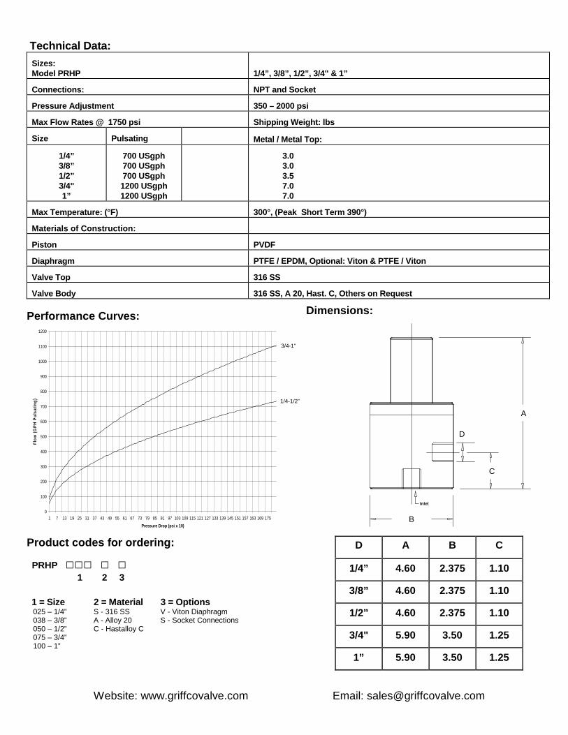
Technical Data:
Sizes:Model PRHP 1/4”, 3/8”, 1/2”, 3/4" & 1”
Connections: NPT and Socket
Pressure Adjustment 350 – 2000 psi
Max Flow Rates @ 1750 psi Shipping Weight: lbs
Size Pulsating Metal / Metal Top:
1/4”3/8”1/2”3/4"1”
700 USgph700 USgph700 USgph1200 USgph1200 USgph
3.03.03.57.07.0
Max Temperature: (°F) 300°, (Peak Short Term 390°)
Materials of Construction:
Piston PVDF
Diaphragm PTFE / EPDM, Optional: Viton & PTFE / Viton
Valve Top 316 SS
Valve Body 316 SS, A 20, Hast. C, Others on Request
Performance Curves:
0
100
200
300
400
500
600
700
800
900
1000
1100
1200
1 7 13 19 25 31 37 43 49 55 61 67 73 79 85 91 97 103 109 115 121 127 133 139 145 151 157 163 169 175
Pressure Drop (psi x 10)
Flo
w(G
PH
Pu
lsa
tin
g)
Product codes for ordering:
PRHP □□□ □ □1 2 3
1 = Size 2 = Material 3 = Options025 – 1/4” S - 316 SS V - Viton Diaphragm038 – 3/8” A - Alloy 20 S - Socket Connections050 – 1/2” C - Hastalloy C075 – 3/4”100 – 1”
Dimensions:
A
C
B
Inlet
D
D A B C
1/4” 4.60 2.375 1.10
3/8” 4.60 2.375 1.10
1/2” 4.60 2.375 1.10
3/4" 5.90 3.50 1.25
1” 5.90 3.50 1.25
Website: www.griffcovalve.com Email: [email protected]
3/4-1”
1/4-1/2”