grizzly 450 yfm45fgx owner's manual - … introduction ebu17270 congratulations on your...
TRANSCRIPT

READ THIS MANUAL CAREFULLY!It contains important safety information.
This ATV should not be ridden by anyone under 16 years of age.WARNING
OWNER’S MANUAL
17S-F8199-10LIT-11626-21-46
YFM45FGX
DIC2342

EBU17091
U17S10E0.book Page 1 Friday, July 6, 2007 1:37 PM

EBU17170
INTRODUCTIONEBU17270
Congratulations on your purchase of the Yamaha YFM45FGX. This ATV represents the result of manyyears of Yamaha experience in the production of fine sporting, touring, and pace-setting racing machines.With the purchase of this Yamaha, you can now appreciate the high degree of craftsmanship and reliabilitythat have made Yamaha a leader in these fields.This manual will provide you with a good basic understanding of the features and operation of this ATV.This manual includes important safety information. It provides information about special tech-niques and skills necessary to ride the ATV. It also includes basic maintenance and inspection proce-dures. If you have any questions regarding the operation or maintenance of your ATV, please consult aYamaha dealer.
AN IMPORTANT SAFETY MESSAGE:� READ THIS MANUAL TOGETHER WITH TIPS FOR THE ATV RIDER CAREFULLY AND COMPLETE-
LY BEFORE OPERATING YOUR ATV. MAKE SURE YOU UNDERSTAND ALL INSTRUCTIONS.� PAY CLOSE ATTENTION TO THE WARNING AND CAUTION LABELS ON THE ATV.� NEVER OPERATE AN ATV WITHOUT PROPER TRAINING OR INSTRUCTION. FREE TRAINING IS
AVAILABLE TO ANYONE WHO BUYS A NEW ATV. CALL 1-800-887-2887 FOR MORE INFORMA-TION.
� THIS ATV, AND ANY OTHER ATV OVER 90 cc, SHOULD NOT BE RIDDEN BY ANYONE UNDER 16YEARS OF AGE.
U17S10E0.book Page 1 Friday, July 6, 2007 1:37 PM
EBU17330
IMPORTANT MANUAL INFORMATIONEBU17341
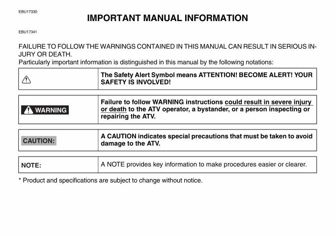
FAILURE TO FOLLOW THE WARNINGS CONTAINED IN THIS MANUAL CAN RESULT IN SERIOUS IN-JURY OR DEATH.Particularly important information is distinguished in this manual by the following notations:
* Product and specifications are subject to change without notice.
The Safety Alert Symbol means ATTENTION! BECOME ALERT! YOUR SAFETY IS INVOLVED!
Failure to follow WARNING instructions could result in severe injury or death to the ATV operator, a bystander, or a person inspecting or repairing the ATV.
A CAUTION indicates special precautions that must be taken to avoid damage to the ATV.
A NOTE provides key information to make procedures easier or clearer.
WARNING
CAUTION:
NOTE:
U17S10E0.book Page 1 Friday, July 6, 2007 1:37 PM
EBU17350
IMPORTANT NOTICEEBU17360
Welcome to the Yamaha world of motor sports!This ATV is designed and manufactured for OFF-ROAD use only. It is illegal and unsafe to operate this ATVon any public street, road or highway.This ATV complies with all applicable OFF-ROAD noise level and spark arrester laws and regulations ineffect at the time of manufacture.Please check your local riding laws and regulations before operating this ATV.
EBU17401
AFFIX DEALER
LABEL HERE
YFM45FGXOWNER’S MANUAL
©2007 by Yamaha Motor Corporation, U.S.A.1st edition, June 2007
All rights reserved.Any reprinting or unauthorized use without the written permission of Yamaha Motor Corporation, U.S.A.
is expressly prohibited.Printed in U.S.A.
P/N LIT-11626-21-46
U17S10E0.book Page 1 Friday, July 6, 2007 1:37 PM

WARNINGEWB00010
Indicates a potential hazard that could resultin serious injury or death.
EBU17420
TABLE OF CONTENTS
SAFETY INFORMATION .............................. 1-1
LOCATION OF THE WARNING AND SPECIFICATION LABELS ............................ 2-1
DESCRIPTION .............................................. 3-1Left view ...................................................... 3-1Right view.................................................... 3-1Controls and instruments ............................ 3-2
INSTRUMENT AND CONTROL FUNCTIONS .................................................. 4-1
Main switch ................................................ 4-1Indicator lights and warning light ................ 4-2Multifunction display ................................... 4-4Fuel gauge ................................................. 4-5Handlebar switches .................................... 4-5
Throttle lever .............................................4-11Speed limiter .............................................4-12Front brake lever .......................................4-13Brake pedal and rear brake lever .............4-14Drive select lever ......................................4-14Recoil starter .............................................4-15Fuel tank cap ............................................4-16Fuel ...........................................................4-16Fuel cock ..................................................4-17Starter (choke) ..........................................4-19Seat ..........................................................4-19Storage compartment ...............................4-20Front carrier ..............................................4-21Rear carrier ...............................................4-22Adjusting the front and rear shock
absorber assemblies ...............................4-22Trailer hitch ...............................................4-23Auxiliary DC jack .......................................4-24
PRE-OPERATION CHECKS ..........................5-1Pre-operation check list ..............................5-1Fuel .............................................................5-4Engine oil ....................................................5-4Final gear oil ...............................................5-4Differential gear oil ......................................5-4Coolant .......................................................5-4Front and rear brakes .................................5-5
U17S10E0.book Page 1 Friday, July 6, 2007 1:37 PM
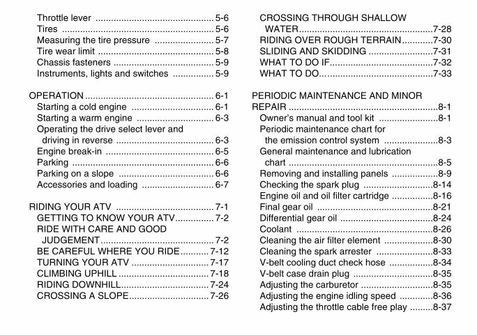
Throttle lever .............................................. 5-6Tires ........................................................... 5-6Measuring the tire pressure ....................... 5-7Tire wear limit ............................................. 5-8Chassis fasteners ....................................... 5-9Instruments, lights and switches ................ 5-9
OPERATION .................................................. 6-1Starting a cold engine ................................ 6-1Starting a warm engine .............................. 6-3Operating the drive select lever and
driving in reverse ...................................... 6-3Engine break-in .......................................... 6-5Parking ....................................................... 6-6Parking on a slope ..................................... 6-6Accessories and loading ............................ 6-7
RIDING YOUR ATV ...................................... 7-1GETTING TO KNOW YOUR ATV............... 7-2RIDE WITH CARE AND GOOD
JUDGEMENT............................................ 7-2BE CAREFUL WHERE YOU RIDE........... 7-12TURNING YOUR ATV .............................. 7-17CLIMBING UPHILL ................................... 7-18RIDING DOWNHILL.................................. 7-24CROSSING A SLOPE............................... 7-26
CROSSING THROUGH SHALLOW WATER....................................................7-28
RIDING OVER ROUGH TERRAIN............7-30SLIDING AND SKIDDING .........................7-31WHAT TO DO IF........................................7-32WHAT TO DO............................................7-33
PERIODIC MAINTENANCE AND MINOR REPAIR ..........................................................8-1
Owner’s manual and tool kit .......................8-1Periodic maintenance chart for
the emission control system .....................8-3General maintenance and lubrication
chart ..........................................................8-5Removing and installing panels ..................8-9Checking the spark plug ...........................8-14Engine oil and oil filter cartridge ................8-16Final gear oil .............................................8-21Differential gear oil ....................................8-24Coolant .....................................................8-26Cleaning the air filter element ...................8-30Cleaning the spark arrester ......................8-33V-belt cooling duct check hose .................8-34V-belt case drain plug ...............................8-35Adjusting the carburetor ............................8-35Adjusting the engine idling speed .............8-36Adjusting the throttle cable free play .........8-37
U17S10E0.book Page 2 Friday, July 6, 2007 1:37 PM

Valve clearance ........................................ 8-37Adjusting the drive select lever safety
system cable .......................................... 8-38Checking the front brake pads and
rear brake friction plates ......................... 8-38Checking the brake fluid level .................. 8-39Changing the brake fluid .......................... 8-40Checking the front brake lever free
play ......................................................... 8-40Adjusting the brake pedal and rear brake
lever free play and checking the brake pedal position ......................................... 8-41
Axle boots ................................................ 8-45Brake light switches ................................. 8-46Checking and lubricating the cables ........ 8-47Checking and lubricating the front and
rear brake levers .................................... 8-47Checking and lubricating the brake
pedal ...................................................... 8-48Checking the wheel hub bearings ............ 8-48Lubricating the drive shaft universal
joint ......................................................... 8-48Checking the stabilizer bushes ................ 8-49Lubricating the rear knuckle pivots ........... 8-49Lubricating the steering shaft ................... 8-49Battery ...................................................... 8-50Replacing a fuse ...................................... 8-52
Replacing a headlight bulb .......................8-54Adjusting a headlight beam ......................8-56Replacing the tail/brake light bulb .............8-56Removing a wheel ....................................8-58Installing a wheel ......................................8-58Troubleshooting ........................................8-60Troubleshooting charts .............................8-61
CLEANING AND STORAGE ..........................9-1Cleaning ......................................................9-1Storage .......................................................9-2
SPECIFICATIONS .......................................10-1
CONSUMER INFORMATION.......................11-1Identification numbers ...............................11-1Noise regulation ........................................11-3Maintenance record ..................................11-4YAMAHA MOTOR CORPORATION,
U.S.A. ATV LIMITED WARRANTY .........11-5YAMAHA EXTENDED SERVICE
(Y.E.S.) ...................................................11-7
U17S10E0.book Page 3 Friday, July 6, 2007 1:37 PM

1-1
1
EBU17430
SAFETY INFORMATION
EBU17482
AN ATV IS NOT A TOY AND CAN BE HAZARD-OUS TO OPERATE.An ATV handles differently from other vehicles, in-cluding motorcycles and cars. A collision or roll-over can occur quickly, even during routinemaneuvers such as turning and riding on hills orover obstacles, if you fail to take proper precau-tions.SEVERE INJURY OR DEATH can result if you donot follow these instructions:� Read this manual and all labels carefully and fol-
low the operating procedures described.� Never operate an ATV without proper training or
instruction. Take a Training Course. Beginnersshould receive training from a certified instruc-tor. Contact an authorized ATV dealer or call 1-800-887-2887 to find out about the trainingcourses nearest you.
� Always follow the age recommendation:– A child under 16 years old should never oper-ate an ATV with engine size greater than 90 cc.
� Never allow a child under age 16 to operate anATV without adult supervision, and never allowcontinued use of an ATV by a child if he or shedoes not have the abilities to operate it safely.
� Never carry a passenger on an ATV.� Always avoid operating an ATV on any paved
surfaces, including sidewalks, driveways, park-ing lots and streets.
� Never operate an ATV on any public street, roador highway, even a dirt or gravel one.
� Never operate an ATV without wearing an ap-proved motorcycle helmet that fits properly. Youshould also wear eye protection (goggles or faceshield), gloves, boots, a long-sleeved shirt or ajacket, and long pants.
� Never consume alcohol or drugs before or whileoperating this ATV.
� Never operate at speeds too fast for your skillsor the riding conditions. Always go at a speedthat is proper for the terrain, visibility, operatingconditions, and your experience.
� Never attempt wheelies, jumps, or other stunts.
U17S10E0.book Page 1 Friday, July 6, 2007 1:37 PM

1-2
1
� Always inspect your ATV each time you use it tomake sure it is in safe operating condition. Al-ways follow the inspection and maintenanceprocedures and schedules described in thismanual.
� Always keep both hands on the handlebars andboth feet on the footboards of the ATV duringoperation.
� Always go slowly and be extra careful when op-erating on unfamiliar terrain. Always be alert tochanging terrain conditions when operating theATV.
� Never operate on excessively rough, slippery orloose terrain until you have learned and prac-ticed the skills necessary to control the ATV onsuch terrain. Always be especially cautious onthese kinds of terrain.
� Always follow proper procedures for turning asdescribed in this manual. Practice turning at lowspeeds before attempting to turn at fasterspeeds and never turn at excessive speeds.
� Never operate the ATV on hills too steep for theATV or for your abilities. Practice on smaller hillsbefore attempting larger hills.
� Always follow proper procedures for climbinghills as described in this manual. Check the ter-rain carefully before you start up any hill. Neverclimb hills with excessively slippery or loose sur-faces. Shift your weight forward. Never open thethrottle suddenly. Never go over the top of a hillat high speed.
� Always follow proper procedures for going downhills and for braking on hills as described in thismanual. Check the terrain carefully before youstart down any hill. Shift your weight backward.Never go down a hill at high speed. Avoid goingdown a hill at an angle that would cause the ve-hicle to lean sharply to one side. Go straightdown the hill where possible.
� Always follow proper procedures for crossingthe side of a hill as described in this manual.Avoid hills with excessively slippery or loose sur-faces. Shift your weight to the uphill side of theATV. Never attempt to turn the ATV around onany hill until you have mastered the turning tech-nique described in this manual on level ground.Avoid crossing the side of a steep hill if possible.
� Always use proper procedures if you stall or rollbackwards when climbing a hill. To avoid stall-ing, use the proper gear range and maintain a
U17S10E0.book Page 2 Friday, July 6, 2007 1:37 PM

1-3
1
steady speed when climbing a hill. If you stall orroll backwards, follow the special procedure forbraking described in this manual. Dismount onthe uphill side or to a side if pointed straight up-hill. Turn the ATV around and remount, followingthe procedure described in this manual.
� Always check for obstacles before operating in anew area.
� Never attempt to operate over large obstacles,such as large rocks or fallen trees. Always followproper procedures when operating over obsta-cles as described in this manual.
� Always be careful when skidding or sliding.Learn to safely control skidding or sliding bypracticing at low speeds and on level, smoothterrain. On extremely slippery surfaces, such asice, go slowly and be very cautious in order to re-duce the chance of skidding or sliding out of con-trol.
� Never operate an ATV in fast flowing water or inwater deeper than that recommended in thismanual. Remember that wet brakes may havereduced stopping ability. Test your brakes afterleaving water. If necessary, apply them severaltimes to let friction dry out the linings.
� Always be sure there are no obstacles or peoplebehind you when you operate in reverse. Whenit is safe to proceed in reverse, go slowly.
� Always use the size and type of tires specified inthis manual.
� Always maintain proper tire pressure as de-scribed in this manual.
� Never modify an ATV through improper installa-tion or use of accessories.
� Never exceed the stated load capacity for anATV. Cargo should be properly distributed andsecurely attached. Reduce speed and follow in-structions in this manual for carrying cargo orpulling a trailer. Allow greater distance for brak-ing.
FOR MORE INFORMATION ABOUT ATV SAFE-TY, call the Consumer Products Safety Commis-sion at 1-800-638-2772, or the ATV Distributor’sSafety Hotline at 1-800-852-5344.
U17S10E0.book Page 3 Friday, July 6, 2007 1:37 PM

1-4
1WARNING
EWB00021
WARNINGEWB00030
POTENTIAL HAZARDImproper handling of gasoline.WHAT CAN HAPPENGasoline can catch fire and you could beburned.HOW TO AVOID THE HAZARDAlways turn off the engine when refueling.Do not refuel right after the engine has beenrunning and is still very hot.Do not spill gasoline on the engine or ex-haust pipe/muffler when refueling.Never refuel while smoking, or in the vicinityof sparks, open flames, or other sources ofignition such as the pilot lights of waterheaters and clothes dryers.When transporting the ATV in another vehi-cle, be sure it is kept upright and that thefuel cock is in the “OFF” position. Other-wise, fuel may leak out of the carburetor orfuel tank.WHAT CAN HAPPENGasoline is poisonous and can cause inju-ries.
HOW TO AVOID THE HAZARDIf you should swallow some gasoline or in-hale a lot of gasoline vapor, or get some gas-oline in your eyes, seek medical helpimmediately. If gasoline spills on your skin,wash with soap and water. If gasoline spillson your clothing, change your clothes.
POTENTIAL HAZARDStarting or running the engine in a closed ar-ea.
U17S10E0.book Page 4 Friday, July 6, 2007 1:37 PM

1-5
1
WHAT CAN HAPPENExhaust fumes are poisonous and maycause loss of consciousness and deathwithin a short time.HOW TO AVOID THE HAZARDAlways operate your ATV in an area with ad-equate ventilation.
U17S10E0.book Page 5 Friday, July 6, 2007 1:37 PM

2-1
2
EBU17660
LOCATION OF THE WARNING AND SPECIFICATION LABELS
U17S10E0.book Page 1 Friday, July 6, 2007 1:37 PM

2-2
2
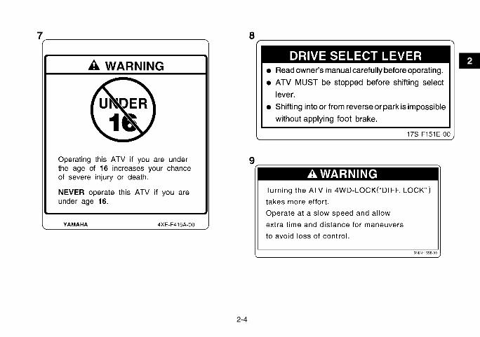
EBU17670
Read and understand all of the labels on your ATV. These labels contain important information for safe andproper operation.Never remove any labels from your ATV. If a label becomes difficult to read or comes off, request a replace-ment label from your Yamaha dealer.
U17S10E0.book Page 2 Friday, July 6, 2007 1:37 PM

2-3
2
U17S10E0.book Page 3 Friday, July 6, 2007 1:37 PM
2-4
2
U17S10E0.book Page 4 Friday, July 6, 2007 1:37 PM

3-1
3
EBU17680
DESCRIPTION EBU17690
Left viewEBU17700
Right view
1. Radiator cap2. Fuel cock3. Recoil starter4. Throttle stop screw5. Air filter case6. Battery7. Fuses8. Tail/brake light9. Engine oil filler cap10.Oil filter cartridge11.Coolant reservoir12.V-belt cooling duct check hose
1. Trailer hitch receiver2. Rear shock absorber assembly spring preload adjusting
ring3. Spark arrester4. Storage compartment and tool kit5. Spark plug6. Front shock absorber assembly spring preload adjusting
ring7. Rear brake light switch8. Brake pedal9. V-belt case drain plug
U17S10E0.book Page 1 Friday, July 6, 2007 1:37 PM

3-2
3
EBU17712
Controls and instruments NOTE:The ATV you have purchased may differ slightlyfrom the figures shown in this manual.
1. Rear brake lever2. Handlebar switches3. Starter (choke)4. Drive select lever5. Multifunction display6. Main switch7. Fuel tank cap8. Auxiliary DC jack9. On-Command four-wheel-drive/differential gear lock
switch10.Throttle lever11.Front brake lever
U17S10E0.book Page 2 Friday, July 6, 2007 1:37 PM

4-1
4
EBU17722
INSTRUMENT AND CONTROL FUNCTIONS
WARNINGEWB00010
Indicates a potential hazard that could result inserious injury or death.
EBU17760
Main switch The positions of the main switch are as follows:
ONAll electrical systems are supplied with power. Theheadlights and taillight come on when the lightswitch is on, and the engine can be started. Thekey cannot be removed.
OFFAll electrical systems are off. The key can be re-moved.
1. Main switch
U17S10E0.book Page 1 Friday, July 6, 2007 1:37 PM

4-2
4
EBU17813
Indicator lights and warning light
EBU17842
Reverse indicator light “ ” This indicator light comes on when the transmis-sion is in the reverse position.
Furthermore, this indicator light flashes when theengine is being raced for 10 seconds or more.
NOTE:If the indicator light flashes under any other circum-stances or the speedometer does not show thespeed while riding, have a Yamaha dealer checkthe speed sensor circuit.
EBU17860
Neutral indicator light “ ” This indicator light comes on when the transmis-sion is in the neutral position.
EBU17920
Coolant temperature warning light “ ” This warning light comes on when the engine over-heats. When this occurs during operation, stop theengine as soon as it is safe to do so and allow it tocool down for about 10 minutes.
CAUTION:ECB00010
� The engine may overheat if the ATV is over-loaded. In this case, reduce the load to spec-ification.
1. On-Command differential gear lock indicator light “DIFF. LOCK”
2. Low-range indicator light “L”3. High-range indicator light “H”4. Neutral indicator light “N”5. Reverse indicator light “R”6. Park indicator light “P”7. On-Command four-wheel-drive/differential gear lock
indicator “ ”/“ ”8. Coolant temperature warning light “ ”
U17S10E0.book Page 2 Friday, July 6, 2007 1:37 PM

4-3
4
� Start the engine after making sure that thewarning light is out. Continuous use whilethe warning light is on may cause damage tothe engine.
EBU17961
On-Command four-wheel-drive/differential gear lock indicator “ ”/“ ” The On-Command four-wheel-drive indicator “ ”comes on when the On-Command four-wheel-drive switch is set to the “4WD” position.The On-Command differential gear lockindicator “ ” in the On-Command four-wheel-drive indicator also comes on when the On-Com-mand differential gear lock switch is set to the“LOCK” position.
NOTE:� Due to the synchronizing mechanism in the dif-
ferential gear case, the four-wheel-drive indica-tor may not come on until the ATV starts moving.
� When the On-Command differential gear lockswitch is set to “LOCK”, the indicator “ ” willflash until the differential gear is locked.
EBU17970
Park indicator light “ ” This indicator light comes on when the transmis-sion is in the park position.
EBU17980
High-range indicator light “ ” This indicator light comes on when the transmis-sion is in the high-range position.
EBU17990
Low-range indicator light “ ” This indicator light comes on when the transmis-sion is in the low-range position.
EBU18001
On-Command differential gear lock indicator light “DIFF. LOCK” This indicator light and the On-Command differen-tial gear lock indicator in the display come on whenthe On-Command differential gear lock switch isset to the “LOCK” position.
NOTE:When the switch is set to “LOCK”, the On-Com-mand differential gear lock indicator light will flashuntil the differential gear is locked.
U17S10E0.book Page 3 Friday, July 6, 2007 1:37 PM

4-4
4
EBU18031
Multifunction display
The speedometer unit is equipped with the follow-ing:� a speedometer (which shows the riding speed)� an odometer (which shows the total distance
traveled)� two tripmeters (which show the distance trav-
eled since they were last set to zero)
� a clock� an hour meter (which shows the total time the
key has been turned to “ON”)
Odometer and tripmeter modesPushing the “TRIP/ODO” button switches the dis-play between the odometer mode “ODO” and thetripmeter modes “A” and “B” in the following order:ODO → TRIP A → TRIP B → ODOTo reset a tripmeter, select it by pushing the“TRIP/ODO” button, and then push the“TRIP/ODO” button for at least three seconds. Thetripmeters can be used to estimate the distancethat can be traveled with a full tank of fuel. This in-formation will enable you to plan future fuel stops.
NOTE:Holding in the “TRIP/ODO” button and then turningthe key to “ON” switches the display between“mph” and “km/h”.
Clock modePushing the “ ”/“ ” button switches the displaybetween the clock mode “CLOCK” and the hourmeter mode “HOUR” in the following order:CLOCK → HOUR → CLOCK
1. Speedometer2. “H” button3. “M” button4. Clock/Hour meter5. Odometer/Tripmeter A/Tripmeter B6. “TRIP/ODO” button7. Clock/Hour “ ”/“ ” button
U17S10E0.book Page 4 Friday, July 6, 2007 1:37 PM

4-5
4
To set the clock1. Set the display to the clock mode.2. Push the “ ”/“ ” button until the clock starts
flashing.3. Set the hours by pushing the “H” button.4. Set the minutes by pushing the “M” button.5. Push the “ ”/“ ” button, and then release it
to start the clock.
EBU18050
Fuel gauge The fuel gauge indicates the amount of fuel in thefuel tank. When the needle reaches the red line, re-fill the tank at the first opportunity.
NOTE:If the ATV runs out of fuel, move the fuel cock leverto the “RES” position. Approximately 4.5 L (1.19US gal) (0.99 Imp.gal) of fuel will be remaining inthe tank.
EBU18061
Handlebar switches
1. Fuel gauge2. Red line
1. Light switch “ / /OFF”2. Start switch “ ”3. Engine stop switch “ / ”4. Override switch “OVERRIDE”
U17S10E0.book Page 5 Friday, July 6, 2007 1:37 PM

4-6
4
EBU18080
Engine stop switch “ / ” Set this switch to “ ” before starting the engine.The engine stop switch controls the ignition andstops the engine when it is running. Use this switchto stop the engine in an emergency situation. Theengine will not start or run when this switch is setto “ ”.
EBU18100
Start switch “ ” Push this switch to crank the engine with the start-er.
CAUTION:ECB00050
See the starting instructions on page 6-1 priorto starting the engine.
EBU18151
Light switch “ / /OFF” Set this switch to “ ” to turn on the low beamsand the taillight. Set the switch to “ ” to turn onthe high beams and the taillight. Set the switch to“OFF” to turn off all the lights.
CAUTION:ECB00040
Do not use the headlights with the engineturned off for an extended period of time, oth-erwise the battery may discharge to the pointthat the starter motor will not operate properly.If this should happen, remove the battery andrecharge it.
EBU18180
Override switch “OVERRIDE”
Top speed is normally limited when operating indifferential gear lock. If conditions require more en-gine power when riding forward, push and hold this
1. Override switch “OVERRIDE”
U17S10E0.book Page 6 Friday, July 6, 2007 1:37 PM

4-7
4
switch to override the differential gear lock speedlimiting function. (See page 4-9.) Releasing theswitch restores the speed limiting function.While the override switch is pushed, the segmentsof the speedometer digits will appear as shown inthe figure.
NOTE:If the digits of the speedometer appear as shownwhen the switch is NOT being pushed, this couldindicate a malfunction in the electrical system. Inthis case, take the ATV to a Yamaha dealer at thefirst opportunity.
WARNINGEWB00110
EBU26633
On-Command four-wheel-drive switch “2WD”/“4WD” This ATV is equipped with a switch to change fromtwo-wheel drive to four-wheel drive and vice-versa.Select the appropriate drive according to the ter-rain and the conditions.� “2WD” (two-wheel drive): Power is supplied to
the rear wheels.
POTENTIAL HAZARDRiding too fast while the ATV is in four-wheel-drive differential gear lock.WHAT CAN HAPPENAll wheels turn at the same speed when thedifferential is locked, so it takes more effortto turn the ATV. The effort needed to turn in-creases with the riding speed. You may losecontrol and have an accident if you cannotmake a sharp enough turn for the speed youare traveling.HOW TO AVOID THE HAZARDAlways ride at a slow speed when the ATV isin four-wheel-drive differential gear lock, andallow extra time and distance for maneuvers.
U17S10E0.book Page 7 Friday, July 6, 2007 1:37 PM

4-8
4
� “4WD” (four-wheel drive): Power is supplied tothe rear and front wheels.
To change from two-wheel drive to four-wheeldrive, stop the ATV and push the switch in to the“4WD” position. Then, the four-wheel-driveindicator “ ” comes on in the multifunction dis-play.To change from four-wheel drive to two-wheeldrive, stop the ATV and push the switch in to the“2WD” position.
WARNINGEWB00120
1. On-Command four-wheel-drive switch “2WD”/“4WD”
POTENTIAL HAZARDChanging from two-wheel drive to four-wheel drive or from four-wheel drive to two-wheel drive while the ATV is moving.WHAT CAN HAPPENThe ATV handles differently in two-wheeldrive than in four-wheel drive in some cir-cumstances. Changing from two-wheel driveto four-wheel drive or from four-wheel driveto two-wheel drive while moving may causethe ATV to unexpectedly handle differently.This could distract the operator and in-crease the risk of losing control and of caus-ing an accident.HOW TO AVOID THE HAZARDAlways stop the ATV before changing fromtwo-wheel drive to four-wheel drive or vice-versa.
U17S10E0.book Page 8 Friday, July 6, 2007 1:37 PM

4-9
4
EBU18243
On-Command differential gear lock switch “4WD”/“LOCK” This ATV is equipped with a switch allowing you tolock the differential gear when in four-wheel drive.Select the appropriate switch position according tothe terrain and the conditions.� “4WD” (four-wheel drive): Power is supplied to
the rear and front wheels.� “LOCK” (four-wheel drive with the differential
gear locked): Power is supplied to the rear andfront wheels and the differential gear is locked.Unlike in four-wheel drive, all wheels turn at thesame speed.
To lock the differential gear in four-wheel drive,make sure the On-Command four-wheel-driveswitch is pushed in to the “4WD” position.
Stop the ATV, move the differential gear lock leverto position (a), and then push the differential gearlock switch in to the “LOCK” position. When the dif-ferential gear is locked, the differential gear lock in-dicator “DIFF. LOCK” will come on along with theindicator “ ” in the multifunction display.
1. On-Command four-wheel-drive switch “2WD”/“4WD”2. On-Command differential gear lock switch “4WD”/“LOCK”
1. Differential gear lock lever2. On-Command four-wheel-drive switch “2WD”/“4WD”
U17S10E0.book Page 9 Friday, July 6, 2007 1:37 PM

4-10
4
To release the differential gear lock, stop the ATVand push the switch to the “4WD” position.
WARNINGEWB00091
1. On-Command differential gear lock switch “4WD”/“LOCK”
POTENTIAL HAZARDChanging from four-wheel drive to four-wheel-drive differential gear lock or vice-ver-sa while the ATV is moving.
WHAT CAN HAPPENThe ATV handles differently in four-wheeldrive than in differential gear lock in somecircumstances. Changing from four-wheeldrive to differential gear lock or vice-versawhile moving may cause the ATV to handledifferently unexpectedly. This could distractthe operator and increase the risk of losingcontrol and causing an accident.HOW TO AVOID THE HAZARDAlways stop the ATV before changing fromfour-wheel drive to four-wheel-drive differen-tial gear lock or vice-versa.
U17S10E0.book Page 10 Friday, July 6, 2007 1:37 PM

4-11
4
WARNINGEWB00101
NOTE:� When the switch is set to “LOCK”, the differential
gear lock indicator and indicator light will flashuntil the differential gear is locked.
� When the indicator and indicator light are flash-ing, turning the handlebar back and forth willhelp the differential gear lock to engage.
� Riding before the differential gear lock is proper-ly engaged (e.g., when the indicator and indica-tor light are flashing) will cause the engine speedto be limited until engagement is complete.
� When the ATV is in four-wheel-drive differentialgear lock, the maximum traveling speed is limit-ed to 35 km/h (22 mi/h). However, if conditionsrequire full engine power to be available, pushand hold the override switch to disable the differ-ential gear lock speed limiter. (See page 4-6 fora detailed explanation of this switch.)
EBU18270
Throttle lever Once the engine is running, movement of the throt-tle lever will increase the engine speed.Regulate the speed of the ATV by varying thethrottle position. Because the throttle is spring-loaded, the ATV will decelerate, and the engine willreturn to an idle any time the hand is removed fromthe throttle lever.
POTENTIAL HAZARDRiding too fast while the ATV is in four-wheel-drive differential gear lock.WHAT CAN HAPPENAll wheels turn at the same speed when thedifferential gear is locked, so it takes moreeffort to turn the ATV. The effort needed toturn increases with the riding speed. Youmay lose control and have an accident if youcannot make a sharp enough turn for thespeed you are traveling.HOW TO AVOID THE HAZARDAlways ride at a slow speed when the ATV isin differential gear lock, and allow extra timeand distance for maneuvers.
U17S10E0.book Page 11 Friday, July 6, 2007 1:37 PM

4-12
4
Before starting the engine, check the throttle to besure it is operating smoothly. Make sure it returnsto the idle position as soon as the lever is released.
WARNINGEWB00200
EBU18311
Speed limiter Your ATV was delivered with an adjustable speedlimiter. The speed limiter keeps the throttle fromfully opening, even when the throttle lever ispushed to the maximum.
1. Loosen the locknut.2. To increase the maximum engine power avail-
able and the maximum speed of the ATV, turnthe adjusting screw in direction (a). To de-crease the maximum engine power availableand the maximum speed of the ATV, turn theadjusting screw in direction (b).
1. Throttle lever
POTENTIAL HAZARDMalfunction of throttle.WHAT CAN HAPPENThe throttle could be hard to operate, mak-ing it difficult to speed up or slow downwhen you need to. This could cause an acci-dent.
HOW TO AVOID THE HAZARDCheck the operation of the throttle lever be-fore you start the engine. If it does not worksmoothly, check for the cause. Correct theproblem before riding the ATV. Consult aYamaha dealer if you can’t find or solve theproblem yourself.
U17S10E0.book Page 12 Friday, July 6, 2007 1:37 PM

4-13
4
3. Tighten the locknut.
WARNINGEWB00190
EBU18391
Front brake lever The front brake lever is located on the right handle-bar. To apply the front brake, pull the brake levertoward the handlebar grip.
1. Locknut2. Adjusting screw3. No more than 12 mm (0.47 in)
POTENTIAL HAZARDImproper adjustment of the speed limiterand throttle.WHAT CAN HAPPENThe throttle cable could be damaged. Im-proper throttle operation could result. Youcould lose control, have an accident or be in-jured.
HOW TO AVOID THE HAZARDDo not turn the adjusting screw out morethan 12 mm (0.47 in). Always make sure thethrottle lever free play is adjusted to 3.0–5.0mm (0.12–0.20 in). (See page 8-37.)
1. Front brake lever
U17S10E0.book Page 13 Friday, July 6, 2007 1:37 PM

4-14
4
EBU18442
Brake pedal and rear brake lever The brake pedal is located on the right side of theATV and the rear brake lever is located on the lefthandlebar. To apply the rear brake, push down onthe brake pedal or pull the brake lever toward thehandlebar grip.
EBU18611
Drive select lever The drive select lever is used to shift your ATV intothe low-range, high-range, neutral, reverse andpark positions. See the “Operating the drive selectlever and driving in reverse” section on page 6-3for the drive select lever operation.
1. Brake pedal
1. Rear brake lever
U17S10E0.book Page 14 Friday, July 6, 2007 1:37 PM
4-15
4
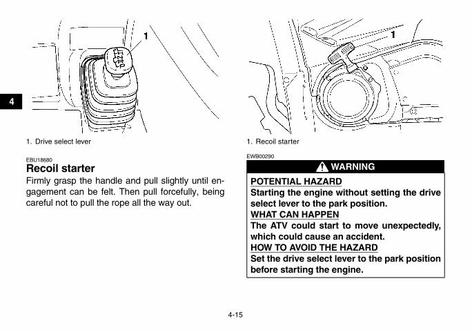
EBU18680
Recoil starter Firmly grasp the handle and pull slightly until en-gagement can be felt. Then pull forcefully, beingcareful not to pull the rope all the way out.
WARNINGEWB00290
1. Drive select lever 1. Recoil starter
POTENTIAL HAZARDStarting the engine without setting the driveselect lever to the park position.WHAT CAN HAPPENThe ATV could start to move unexpectedly,which could cause an accident.HOW TO AVOID THE HAZARDSet the drive select lever to the park positionbefore starting the engine.
U17S10E0.book Page 15 Friday, July 6, 2007 1:37 PM

4-16
4
EBU18720
Fuel tank cap Remove the fuel tank cap by turning it counter-clockwise.
EBU18730
Fuel Make sure that there is sufficient fuel in the tank.Fill the fuel tank to the bottom of the filler tube asshown.
1. Fuel tank cap
1. Fuel level2. Fuel tank filler tube
Recommended fuel:UNLEADED GASOLINE ONLY
Fuel tank capacity:15.0 L (3.96 US gal) (3.30 Imp.gal)
Fuel reserve amount:4.5 L (1.19 US gal) (0.99 Imp.gal)
U17S10E0.book Page 16 Friday, July 6, 2007 1:37 PM

4-17
4
CAUTION:ECB00070
Use only unleaded gasoline. The use of leadedgasoline will cause severe damage to internalengine parts, such as the valves and pistonrings, as well as to the exhaust system.
Your Yamaha engine has been designed to useregular unleaded gasoline with a pump octanenumber [(R+M)/2] of 86 or higher, or a research oc-tane number of 91 or higher. If knocking or pingingoccurs, use a different brand of gasoline or premi-um unleaded fuel. Unleaded fuel will give you long-er spark plug life and reduced maintenance cost.
GasoholThere are two types of gasohol: gasohol contain-ing ethanol and that containing methanol. Gasoholcontaining ethanol can be used if the ethanol con-tent does not exceed 10%. Gasohol containingmethanol is not recommended by Yamaha be-cause it can cause damage to the fuel system orATV performance problems.
WARNINGEWB00270
EBU18820
Fuel cock The fuel cock supplies fuel from the tank to the car-buretor while also filtering it.The fuel cock lever positions are explained as fol-lows and shown in the illustrations.
POTENTIAL HAZARDImproper care when refueling.
WHAT CAN HAPPENFuel can spill, which can cause a fire and se-vere injury.Fuel expands when it heats up. If the fueltank is overfilled, fuel could spill out due toheat from the engine or the sun.HOW TO AVOID THE HAZARDDo not overfill the fuel tank. Be careful not tospill fuel, especially on the engine or ex-haust pipe. Wipe up any spilled fuel immedi-ately. Be sure the fuel tank cap is closedsecurely.Do not refuel right after the engine has beenrunning and is still very hot.
U17S10E0.book Page 17 Friday, July 6, 2007 1:37 PM

4-18
4
OFF
With the fuel cock lever in this position, fuel will notflow. Always turn the fuel cock lever to this positionwhen the engine is not running.
ON
With the fuel cock lever in this position, fuel flowsto the carburetor. Turn the fuel cock lever to thisposition when starting the engine and riding.
1. Arrow mark pointing to “OFF” 1. Arrow mark pointing to “ON”
U17S10E0.book Page 18 Friday, July 6, 2007 1:37 PM

4-19
4
RES
This indicates reserve. With the fuel cock lever inthis position, the fuel reserve is made available.Turn the fuel cock lever to this position if you runout of fuel while riding. When this occurs, refuel assoon as possible and be sure to turn the fuel cocklever back to “ON”!
EBU18850
Starter (choke) “ ” Starting a cold engine requires a richer air-fuel mix-ture, which is supplied by the starter (choke).Move the starter (choke) in direction (a) to turn onthe starter (choke).
Move the starter (choke) in direction (b) to turn offthe starter (choke).See the “Starting a cold engine” section on page6-1 for proper operation.
EBU18880
Seat
To remove the seatPull the seat lock lever upward and pull up the seatat the rear.
1. Arrow mark pointing to “RES”
1. Starter (choke) “ ”
U17S10E0.book Page 19 Friday, July 6, 2007 1:37 PM

4-20
4
To install the seatInsert the projections on the front of the seat intothe seat holders and push down on the seat at therear.
NOTE:Make sure that the seat is securely fitted.
EBU18941
Storage compartment The storage compartment is located under theseat. (See page 4-19.)When storing any documents in the storage com-partment, be sure to wrap them in a plastic bag sothat they will not get wet. When washing the ATV,be careful not to let any water enter the storagecompartment.
1. Seat2. Seat lock lever
1. Projection2. Seat holder
U17S10E0.book Page 20 Friday, July 6, 2007 1:37 PM

4-21
4
CAUTION:ECB00130
Do not store metal or sharply edged objects,like tools, in the storage compartment. If theymust be stored, wrap them in appropriatecushion material to prevent damaging the stor-age compartment.
� Do not exceed the load limit of 2.0 kg (4 lb)for the storage compartment.
� Do not exceed the maximum load of 210.0 kg(463 lb) for the ATV.
NOTE:There is a check hose at the bottom of the storagecompartment. If any water collects in this hose, re-move the hose, empty it, and then install it.
EBU18960
Front carrier � Do not exceed the load limit of 40.0 kg (88 lb) for
the front carrier.� Do not exceed the maximum load of 210.0 kg
(463 lb) for the ATV.
1. Storage compartment
1. Storage compartment check hose
U17S10E0.book Page 21 Friday, July 6, 2007 1:37 PM

4-22
4
EBU18970
Rear carrier � Do not exceed the load limit of 80.0 kg (176 lb)
for the rear carrier.� Do not exceed the maximum load of 210.0 kg
(463 lb) for the ATV.
EBU19130
Adjusting the front and rear shock ab-sorber assemblies The spring preload can be adjusted to suit the rid-er’s weight and the riding conditions.Adjust the spring preload as follows.Turn the adjusting ring in direction (a) to increasethe spring preload and thereby harden the suspen-sion, and in direction (b) to decrease the springpreload and thereby soften the suspension.
NOTE:A special wrench can be obtained at a Yamahadealer to make this adjustment.
1. Spring preload adjusting ring2. Position indicator
U17S10E0.book Page 22 Friday, July 6, 2007 1:37 PM

4-23
4
WARNINGEWB00350
EBU28971
Trailer hitch This ATV is equipped with a 5 cm (2 in) trailer hitchreceiver.Trailer towing equipment can be obtained at aYamaha dealer. (See page 6-7 for precaution in-formation.)
1. Special wrench
Spring preload setting:Minimum (soft):
1Standard:
2Maximum (hard):
5
POTENTIAL HAZARDImproper shock absorber assembly adjust-ment.
WHAT CAN HAPPENUneven adjustment can cause poor handlingand loss of stability, which could lead to anaccident.HOW TO AVOID THE HAZARDAlways adjust the shock absorber assem-blies on the left and right side to the samesetting.
U17S10E0.book Page 23 Friday, July 6, 2007 1:37 PM

4-24
4
EBU19180
Auxiliary DC jack The auxiliary DC jack is located at the front rightside of the ATV. The auxiliary DC jack can be usedfor suitable work lights, radios, etc. The auxiliaryDC jack should only be used when the engine isrunning.
1. Set the light switch to “OFF”.2. Start the engine. (See page 6-1.)3. Open the auxiliary DC jack cap, and then in-
sert the accessory power plug into the jack.
1. Trailer hitch receiver 1. Auxiliary DC jack cap
1. Auxiliary DC jack
U17S10E0.book Page 24 Friday, July 6, 2007 1:37 PM

4-25
4
4. When the auxiliary DC jack is not being used,cover it with the cap.
CAUTION:ECB00120
� Do not use accessories requiring more thanthe above maximum capacity. This mayoverload the circuit and cause the fuse toblow.
� If accessories are used without the enginerunning or with the headlights turned on, thebattery will lose its charge and engine start-ing may become difficult.
� Do not use an automotive cigarette lighter orother accessories with a plug that gets hotbecause the jack can be damaged.
WARNINGEWB00010
Indicates a potential hazard that could result inserious injury or death.
Maximum rated capacity for the auxiliary DC jack:
DC 12 V, 120 W (10 A)
U17S10E0.book Page 25 Friday, July 6, 2007 1:37 PM
5-1
5
EBU19200
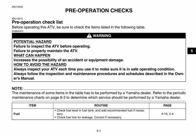
PRE-OPERATION CHECKSEBU19212
Pre-operation check list Before operating this ATV, be sure to check the items listed in the following table.
WARNINGEWB00470
NOTE:The maintenance of some items in the table has to be performed by a Yamaha dealer. Refer to the periodicmaintenance charts on page 8-3 to determine which service should be performed by a Yamaha dealer.
POTENTIAL HAZARDFailure to inspect the ATV before operating.Failure to properly maintain the ATV.WHAT CAN HAPPENIncreases the possibility of an accident or equipment damage.HOW TO AVOID THE HAZARDAlways inspect your ATV each time you use it to make sure it is in safe operating condition.Always follow the inspection and maintenance procedures and schedules described in the Own-er’s Manual.
ITEM ROUTINE PAGE
Fuel• Check fuel level in fuel tank, and add recommended fuel if neces-
sary.• Check fuel line for leakage. Correct if necessary.
4-16, 5-4
U17S10E0.book Page 1 Friday, July 6, 2007 1:37 PM

5-2
5
Engine oil• Check oil level in engine, and add recommended oil to specified lev-
el if necessary.• Check ATV for oil leakage. Correct if necessary.
5-4, 8-16
Final gear oil • Check ATV for oil leakage. Correct if necessary. 5-4, 8-21Differential gear oil • Check ATV for oil leakage. Correct if necessary. 5-4, 8-24
Coolant• Check coolant level in reservoir, and add recommended coolant to
specified level if necessary.• Check cooling system for leakage. Correct if necessary.
5-4, 8-26
Front brake
• Check operation. If soft or spongy, have Yamaha dealer bleed hy-draulic system.
• Check brake pads for wear, and replace if necessary.• Check brake fluid level in reservoir, and add recommended brake
fluid to specified level if necessary.• Check hydraulic system for leakage. Correct if necessary.
5-5, 8-38, 8-39, 8-40
Rear brake• Check operation, and correct if necessary.• Lubricate cables if necessary.• Check lever and pedal free play, and adjust if necessary.
5-5, 8-38, 8-41
Throttle lever• Make sure that operation is smooth. Lubricate cable and lever hous-
ing if necessary.• Check cable free play, and adjust if necessary.
5-6, 8-37
Control cables • Make sure that operation is smooth. Lubricate if necessary. 8-47
Wheels and tires• Check wheel condition, and replace if damaged.• Check tire condition and tread depth. Replace if necessary.• Check air pressure. Correct if necessary.
5-6, 5-7, 5-8
Brake pedal • Make sure that operation is smooth. Lubricate pedal pivoting point if necessary. 8-48
Brake levers • Make sure that operation is smooth. Lubricate lever pivoting points if necessary. 8-47
Axle boots • Check for cracks or damage, and replace if necessary. 8-45Chassis fasteners • Make sure that all nuts, bolts and screws are properly tightened. 5-9
ITEM ROUTINE PAGE
U17S10E0.book Page 2 Friday, July 6, 2007 1:37 PM

5-3
5
Instruments, lights and switches • Check operation, and correct if necessary. 5-9
ITEM ROUTINE PAGE
U17S10E0.book Page 3 Friday, July 6, 2007 1:37 PM

5-4
5
EBU19530
Fuel Make sure that there is sufficient fuel in the tank.(See page 4-16.)
WARNINGEWB00500
EBU19560
Engine oil Make sure that the engine oil is at the specified lev-el. Add oil as necessary. (See page 8-16.)
EBU19590
Final gear oil Make sure that the final gear oil is at the specifiedlevel. Add oil as necessary. (See page 8-21.)
EBU19600
Differential gear oil Make sure that the differential gear oil is at thespecified level. Add oil as necessary. (See page8-24.)
EBU19620
Coolant Make sure that the coolant is at the specified level.Add coolant as necessary. (See page 8-26.)
NOTE:The coolant level must be checked on a cold en-gine since the level varies with engine tempera-ture.
WARNINGEWB00490
POTENTIAL HAZARDImproper care when refueling.WHAT CAN HAPPENFuel can spill, which can cause a fire and se-vere injury.Fuel expands when it heats up. If the fueltank is overfilled, fuel could spill out due toheat from the engine or the sun.HOW TO AVOID THE HAZARDDo not overfill the fuel tank. Be careful not tospill fuel, especially on the engine or ex-haust pipe. Wipe up any spilled fuel immedi-ately. Be sure the fuel tank cap is closedsecurely.Do not refuel right after the engine has beenrunning and is still very hot. POTENTIAL HAZARD
Removing the radiator cap when the engineand radiator are still hot.
U17S10E0.book Page 4 Friday, July 6, 2007 1:37 PM

5-5
5EBU28520
Front and rear brakes
Brake levers and brake pedal� Check that there is no free play in the front brake
lever. If there is free play, have a Yamaha dealercheck the brake system.
� Check for correct free play in the rear brake leverand brake pedal. If the free play is incorrect, ad-just it. (See page 8-41.)
� Check operation of the levers and pedal. Theyshould move smoothly and there should be afirm feeling when the brake is applied. If not,have a Yamaha dealer check them.
Brake fluid level (front brake)Check the brake fluid level. Add fluid if necessary.(See page 8-39.)
Brake fluid leakage (front brake)Check to see if any brake fluid is leaking out of thehose, joint or brake fluid reservoir of the frontbrake. Apply the brake firmly for one minute. If thelever moves slowly inward, there may be a leak inthe brake system. If there is any leakage, the brakesystem should be checked by a Yamaha dealer.
Brake operationTest the brakes at slow speed after starting out tomake sure they are working properly. If the brakesdo not provide proper braking performance, checkthe brake pads and friction plates for wear. (Seepage 8-38.)
WHAT CAN HAPPENYou could be burned by hot fluid and steamblown out under pressure.HOW TO AVOID THE HAZARDWait for the engine to cool before removingthe radiator cap. Always use a thick rag overthe cap. Allow any remaining pressure to es-cape before completely removing the cap.
Recommended brake fluid:DOT 4
U17S10E0.book Page 5 Friday, July 6, 2007 1:37 PM

5-6
5
WARNINGEWB00540
EBU19761
Throttle lever Check the operation of the throttle lever. It mustopen smoothly and spring back to the idle positionwhen released. Have a Yamaha dealer correct ifnecessary.
EBU19801
Tires
WARNINGEWB00551
POTENTIAL HAZARDRiding with improperly operating brakes.WHAT CAN HAPPENYou could lose braking ability, which couldlead to an accident.HOW TO AVOID THE HAZARDAlways check the brakes at the start of everyride. Do not ride the ATV if you find any prob-lem with the brakes. If a problem cannot becorrected by the adjustment procedures pro-vided in this manual, have a Yamaha dealercheck for the cause.
POTENTIAL HAZARDOperating this ATV with improper tires, orwith improper or uneven tire pressure.WHAT CAN HAPPENUse of improper tires on this ATV, or opera-tion of this ATV with improper or uneven tirepressure, may cause loss of control, in-creasing your risk of accident.HOW TO AVOID THE HAZARD� The tires listed below have been approved
by Yamaha Motor Manufacturing Corpora-tion of America for this model. Other tirecombinations are not recommended.Front:
Manufacturer/model:MAXXIS/M979
Size:AT25 x 8-12
Type:Tubeless
U17S10E0.book Page 6 Friday, July 6, 2007 1:37 PM

5-7
5
EBU19820
Measuring the tire pressure Use the low-pressure tire gauge.
Rear:Manufacturer/model:
MAXXIS/M980Size:
AT25 x 10-12Type:
Tubeless� The tires should be set to the recommend-
ed pressure:Recommended tire pressure:
Front:25.0 kPa (3.6 psi) (0.250 kgf/cm²)
Rear:25.0 kPa (3.6 psi) (0.250 kgf/cm²)
• Check and adjust tire pressures whenthe tires are cold.
• Tire pressures must be equal on bothsides.
� Tire pressure below the minimum speci-fied could cause the tire to dislodge fromthe rim under severe riding conditions.Minimum tire pressure:
Front:22.0 kPa (3.2 psi) (0.220 kgf/cm²)
Rear:22.0 kPa (3.2 psi) (0.220 kgf/cm²)
� Use no more than the following pressureswhen seating the tire beads.
� Maximum tire seating pressure:Front:
250 kPa (36 psi) (2.5 kgf/cm²)Rear:
250 kPa (36 psi) (2.5 kgf/cm²)Higher pressures and fast inflation maycause a tire to burst. Inflate the tires veryslowly and carefully.
U17S10E0.book Page 7 Friday, July 6, 2007 1:37 PM

5-8
5
NOTE:The low-pressure tire gauge is included as stan-dard equipment. Make two measurements of thetire pressure and use the second reading. Dust ordirt in the gauge could cause the first reading to beincorrect.
Set the tire pressure when the tires are cold. Setthe tire pressures to the following specifications:
EBU19830
Tire wear limit Replace the tire when the tire groove decreases to3 mm (0.12 in).
1. Low-pressure tire gauge
Recommended pressure:Front
25.0 kPa (3.6 psi) (0.250 kgf/cm²)Rear
25.0 kPa (3.6 psi) (0.250 kgf/cm²)Minimum:
Front22.0 kPa (3.2 psi) (0.220 kgf/cm²)
Rear22.0 kPa (3.2 psi) (0.220 kgf/cm²)
Maximum:Front
28.0 kPa (4.1 psi) (0.280 kgf/cm²)Rear
28.0 kPa (4.1 psi) (0.280 kgf/cm²)
U17S10E0.book Page 8 Friday, July 6, 2007 1:37 PM

5-9
5
EBU19840
Chassis fasteners Make sure that all nuts, bolts and screws are prop-erly tightened.
EBU19850
Instruments, lights and switches Check that all instruments, lights and switches areworking properly. Correct if necessary.
1. Tire wear limit
U17S10E0.book Page 9 Friday, July 6, 2007 1:37 PM

6-1
6
EBU19870
OPERATION
WARNINGEWB00010
Indicates a potential hazard that could result inserious injury or death.
EBU19890
WARNINGEWB00610
EBU20042
Starting a cold engine
WARNINGEWB00620
CAUTION:ECB00150
See the “Engine break-in” section on page 6-5prior to operating the engine for the first time.
1. Turn the fuel cock to “ON”.2. Turn the main switch to “ON” and the engine
stop switch to “ ”.
POTENTIAL HAZARDOperating ATV without being familiar with allcontrols.WHAT CAN HAPPENLoss of control, which could cause an acci-dent or injury.HOW TO AVOID THE HAZARDRead the Owner’s Manual carefully. If there isa control or function you do not understand,ask your Yamaha dealer.
POTENTIAL HAZARDFrozen control cables in cold weather.WHAT CAN HAPPENYou could be unable to control the ATV,which could lead to an accident or collision.HOW TO AVOID THE HAZARDWhen riding in cold weather, always makesure all control cables work smoothly beforeyou begin riding.
U17S10E0.book Page 1 Friday, July 6, 2007 1:37 PM

6-2
6
3. Shift the drive select lever into the neutral orpark position. The corresponding indicatorlight should come on. If the indicator light doesnot come on, have a Yamaha dealer checkthe electrical circuit.
NOTE:The engine can be started under the following con-ditions:� The drive select lever is in the neutral or park po-
sition.� The rear brake lever is applied with the drive se-
lect lever in any position. However, it is recom-mended to shift into the neutral or park positionbefore starting the engine.
4. Use the starter (choke) in reference to the fig-ure:Position (1):Cold engine start with ambient temperaturebelow 5 °C (40 °F).Position (2):Cold engine start with ambient temperaturebetween 0 °C (30 °F) and 30 °C (90 °F).Position (3):Cold engine start with ambient temperatureabove 25 °C (80 °F).
Ambient temp./starter (choke) position
5. Apply the rear brake lever.6. Completely close the throttle lever and start
the engine by pushing the start switch.
NOTE:� If the engine fails to start, release the start
switch, then push it again. Pause a few secondsbefore the next attempt. Each cranking shouldbe as short as possible to preserve battery ener-gy. Do not crank the engine more than 10 sec-onds on each attempt.
1. Fully open2. Half open3. Closed4. Starter (choke)
U17S10E0.book Page 2 Friday, July 6, 2007 1:37 PM
6-3
6
� If the battery is discharged, pull the recoil starterto start the engine.
7. If the engine is started with the starter (choke)in position (1), the starter (choke) should bereturned to position (2) to warm up the engine.If the engine is started with the starter (choke)in position (2), keep the starter (choke) in thisposition to warm up the engine.
CAUTION:ECB00160
For maximum engine life, always warm the en-gine up before starting off. Never acceleratehard when the engine is cold!
8. Continue warming up the engine until it idlessmoothly, then return the starter (choke) toposition (3) before riding.
NOTE:The engine is warm when it responds normally tothe throttle with the starter (choke) turned off.
EBU20291
Starting a warm engine Follow the same procedure as for starting a coldengine, with the exception that the starter (choke)is not required when the engine is warm. Instead,start the engine with the throttle slightly open.
EBU20430
Operating the drive select lever and driving in reverse
CAUTION:ECB00170
Before shifting, stop the ATV, otherwise thetransmission may be damaged.
Shifting: Neutral to High-range and High-rangeto Low-range
1. Bring the ATV to a complete stop.2. Apply the brake pedal, and then shift by mov-
ing the drive select lever along the shift guide.
NOTE:Make sure that the drive select lever is completelyshifted into position.
U17S10E0.book Page 3 Friday, July 6, 2007 1:37 PM

6-4
6
3. Release the brake pedal, and then open thethrottle lever gradually.
Shifting: Neutral to Reverse and Reverse toPark
NOTE:The drive select lever cannot be shifted into or fromreverse or park without applying the brake pedal.
1. Bring the ATV to a complete stop.
2. Apply the brake pedal.3. Shift from neutral to reverse or from reverse to
park and vice versa by moving the drive selectlever along the shift guide.
NOTE:� When in reverse, the reverse indicator light
should come on. If the indicator light does notcome on, have a Yamaha dealer check the elec-trical circuit.
1. Drive select lever2. L (Low-range)3. H (High-range)4. N (Neutral)5. R (Reverse)6. P (Park)
1. Drive select lever2. L (Low-range)3. H (High-range)4. N (Neutral)5. R (Reverse)6. P (Park)
U17S10E0.book Page 4 Friday, July 6, 2007 1:37 PM

6-5
6
� Due to the synchronizing mechanism in the en-gine, the indicator light may not come on until theATV starts moving.
4. Check behind for people or obstacles, andthen release the brake pedal.
5. Open the throttle lever gradually and continueto watch to the rear while backing.
WARNINGEWB00660
EBU20682
Engine break-in
NOTE:� For ATVs equipped with an odometer or an hour
meter, follow the figures given in km (mi) or thefigures given in hours.
� For ATVs not equipped with an odometer orhour meter, follow the figures given in hours.
There is never a more important period in the life ofyour engine than the first 320 km (200 mi) or 20hours of riding. For this reason, you should readthe following material carefully.Since the engine is brand new, do not put an ex-cessive load on it for the first 320 km (200 mi) or 20hours. The various parts in the engine wear andpolish themselves to the correct operating clear-ances. During this period, prolonged full-throttleoperation or any condition that might result in en-gine overheating must be avoided.
0–160 km (0–100 mi) or 0–10 hoursAvoid prolonged operation above 1/2 throttle. Varythe speed of the ATV regularly. Do not operate it atone set throttle position.
160–320 km (100–200 mi) or 10–20 hoursAvoid prolonged operation above 3/4 throttle. Revthe engine freely, but do not use full throttle at anytime.
320 km (200 mi) or 20 hours and beyondThe ATV can now be operated normally.
POTENTIAL HAZARDImproperly operating in reverse.WHAT CAN HAPPENYou could hit an obstacle or even a personbehind you, resulting in serious injury.HOW TO AVOID THE HAZARDWhen you shift into reverse, make sure thereare no people or obstacles behind you.When it is safe to proceed, go slowly.
U17S10E0.book Page 5 Friday, July 6, 2007 1:37 PM

6-6
6
CAUTION:ECB00220
If any engine trouble should occur during theengine break-in period, immediately have aYamaha dealer check the ATV.
EBU20690
Parking When parking the ATV, stop the engine, shift thedrive select lever into the park position, and thenturn the fuel cock to the “OFF” position.
EBU20810
Parking on a slope
WARNINGEWB00780
1. Bring the ATV to a stop by applying thebrakes.
2. Stop the engine.3. With the brake pedal applied, shift the drive
select lever to the park position.
POTENTIAL HAZARDParking on a hill or other incline.WHAT CAN HAPPENThe ATV could roll out of control, increasingthe chance of an accident.
HOW TO AVOID THE HAZARDAvoid parking on hills or other inclines. Ifyou must park on an incline, place the ATVtransversely across the incline, stop the en-gine, shift the drive select lever to the parkposition, and then block the front and rearwheels with rocks or other objects.Do not park the ATV at all on hills that are sosteep you could not walk up them easily.
U17S10E0.book Page 6 Friday, July 6, 2007 1:37 PM

6-7
6
EBU20910
Accessories and loading
EBU20920
AccessoriesAccessories can affect the handling and control ofyour ATV. Keep the following in mind when consid-ering an accessory or operating an ATV which hasaccessories.� Choose only accessories designed for your
ATV. Your Yamaha dealer has a variety of gen-uine Yamaha accessories. Other accessoriesmay also be available on the market. However,it is not possible for Yamaha to test all non-Yamaha accessories, nor control over their qual-ity or suitability. Choose a genuine Yamaha ac-cessory, or one that is equivalent in design andquality.
� Accessories should be rigidly and securelymounted. An accessory which can shift positionor come off while you are riding could affect yourability to control the ATV.
� Do not mount an accessory where it could inter-fere with your ability to control the ATV. Exam-ples include (but are not limited to) a heavy orbulky object attached to the handlebars which
could make steering difficult, an accessory thatlimits your ability to move around on the seat, orone that limits your view.
� Use extra caution when riding an ATV with ac-cessories. The ATV may handle differently thanit does without accessories.
EBU28961
LoadingCargo or a trailer can change the stability and han-dling of an ATV.You must use common sense and good judgmentwhen carrying cargo or towing a trailer. Keep thefollowing points in mind:� Never exceed the weight limits shown. An over-
loaded ATV can be unstable.
U17S10E0.book Page 7 Friday, July 6, 2007 1:37 PM

6-8
6
� Choose a trailer tongue with a coupler designedfor use with a 5 cm (2 in) receiver. (See page4-23 for more information.)
� Do not exceed the maximum tongue weight.You can measure tongue weight with a bath-room scale. Put the tongue of the loaded traileron the scale with the tongue at hitch height. Ad-just the load in the trailer, if necessary, to reduce
the weight on the hitch. If you are carrying cargoand towing a trailer, include the tongue weight inthe maximum ATV load limit.
� Load cargo on the carriers as close to the centerof the ATV as possible. Put cargo at the rear ofthe front carrier, at the front of the rear carrier,and center it.
� Tie down cargo securely to the carriers. Makesure cargo in the trailer cannot move around. Ashifting load can cause an accident.
� Make sure the load does not interfere with con-trols or your ability to see where you are going.
� Ride more slowly than you would without a load.The more weight you carry, the slower youshould go. Although conditions vary, it is goodpractice not to exceed low range whenever youare carrying heavier loads or when towing a trail-er.
� Allow more braking distance. A heavier ATVtakes longer to stop.
� Avoid making sharp turns unless at very slowspeeds.
� Avoid hills and rough terrain. Choose terraincarefully. Added weight affects the stability andhandling of the ATV.
MAXIMUM LOADING LIMITATV loading limit (total weight of rider, cargo, accessories, and tongue):
210.0 kg (463 lb)Front carrier:
40.0 kg (88 lb)Rear carrier:
80.0 kg (176 lb)Storage compartment:
2.0 kg (4 lb)Trailer hitch:
Pulling load (total weight of trailer and car-go):
4900 N (1102 lbf) (500 kgf)Tongue weight (vertical weight on trailer hitch point):
147 N (33 lbf) (15 kgf)
U17S10E0.book Page 8 Friday, July 6, 2007 1:37 PM

6-9
6
WARNINGEWB00750
WARNINGEWB00010
Indicates a potential hazard that could result inserious injury or death.
POTENTIAL HAZARDOverloading this ATV or carrying or towingcargo improperly.WHAT CAN HAPPENCould cause changes in ATV handling whichcould lead to an accident.HOW TO AVOID THE HAZARDNever exceed the stated load capacity forthis ATV.Cargo should be properly distributed and se-curely attached.Reduce speed when carrying cargo or pull-ing a trailer. Allow greater distance for brak-ing.
U17S10E0.book Page 9 Friday, July 6, 2007 1:37 PM

7-1
7
EBU21131
RIDING YOUR ATV
U17S10E0.book Page 1 Friday, July 6, 2007 1:37 PM

7-2
7
WARNINGEWB00010
Indicates a potential hazard that could result inserious injury or death.
EBU21471
GETTING TO KNOW YOUR ATVThis ATV is for recreation and utility use. This sec-tion, Riding your ATV, provides general ATV ridinginstructions for recreational riding. The skills andtechniques described in this section, however, areappropriate for all types of riding. Riding your ATVrequires special skills acquired through practiceover a period of time. Take the time to learn the ba-sic techniques well before attempting more difficultmaneuvers.Riding your new ATV can be a very enjoyable ac-tivity, providing you with hours of pleasure. But it isessential to familiarize yourself with the operationof the ATV to achieve the skill necessary to enjoyriding safely. Before you begin to ride, be sure youhave read this Owner’s Manual completely and un-derstand the operation of the controls. Pay partic-
ular attention to the safety information on pages1-1–1-5. Please also read all caution and warninglabels on your ATV.
RIDE WITH CARE AND GOOD JUDGEMENT
Get training if you are inexperienced.Beginners should get training from a certified in-structor.Become familiar with this ATV at slow speeds first,even if you are an experienced operator. Do not at-tempt to operate at maximum performance untilyou are totally familiar with the ATV’s handling andperformance characteristics.
WARNINGEWB01280
POTENTIAL HAZARDOperating this ATV without proper instruc-tion.WHAT CAN HAPPENThe risk of an accident is greatly increased ifthe operator does not know how to operatethe ATV properly in different situations andon different types of terrain.
U17S10E0.book Page 2 Friday, July 6, 2007 1:37 PM

7-3
7
Riding your ATV requires skills acquiredthrough practice over a period of time.Take the time to learn the basic techniques wellbefore attempting more difficult maneuvers.
Not recommended for children under 16 yearsof age.
WARNINGEWB00901
HOW TO AVOID THE HAZARDBeginning and inexperienced operatorsshould complete the certified trainingcourse offered by Yamaha. They should thenregularly practice the skills learned in thecourse and the operating techniques de-scribed in this Owner’s Manual. For more in-formation about the training course, contactan authorized ATV dealer or call 1-800-887-2887.
POTENTIAL HAZARDFailure to follow the age recommendationsfor this ATV.
WHAT CAN HAPPENUse by children of ATVs that are not recom-mended for their age can lead to severe inju-ry or death of the child.HOW TO AVOID THE HAZARDA child under 16 should never operate anATV with engine size greater than 90 cc.
U17S10E0.book Page 3 Friday, July 6, 2007 1:37 PM
7-4
7
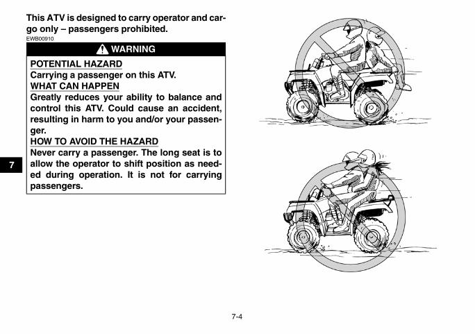
This ATV is designed to carry operator and car-go only – passengers prohibited.
WARNINGEWB00910
POTENTIAL HAZARDCarrying a passenger on this ATV.WHAT CAN HAPPENGreatly reduces your ability to balance andcontrol this ATV. Could cause an accident,resulting in harm to you and/or your passen-ger.HOW TO AVOID THE HAZARDNever carry a passenger. The long seat is toallow the operator to shift position as need-ed during operation. It is not for carryingpassengers.
U17S10E0.book Page 4 Friday, July 6, 2007 1:37 PM

7-5
7
Apparel
WARNINGEWB00920
POTENTIAL HAZARDOperating this ATV without wearing an ap-proved motorcycle helmet, eye protectionand protective clothing.WHAT CAN HAPPENOperating without an approved motorcyclehelmet increases your chances of a severehead injury or death in the event of an acci-dent.Operating without eye protection can resultin an accident and increases your chancesof a severe injury in the event of an accident.Operating without protective clothing in-creases your chances of severe injury in theevent of an accident.
HOW TO AVOID THE HAZARDAlways wear an approved motorcycle helmetthat fits properly.You should also wear:� eye protection (goggles or face shield)� gloves� boots� long-sleeved shirt or jacket� long pants
1. Protective clothing2. Goggles3. Gloves4. Boots5. Helmet
U17S10E0.book Page 5 Friday, July 6, 2007 1:37 PM

7-6
7
Do not operate after consuming alcohol ordrugs.The operator’s performance capability is reducedby the influence of alcohol or drugs.
WARNINGEWB00930
Pre-operation checksAlways perform the pre-operation checks listed onpage 5-1 before riding for proper care of the ATVand to ensure safety.
WARNINGEWB00940
POTENTIAL HAZARDOperating this ATV after consuming alcoholor drugs.WHAT CAN HAPPENCould seriously affect your judgment.Could cause you to react more slowly.Could affect your balance and perception.Could result in an accident.
HOW TO AVOID THE HAZARDNever consume alcohol or drugs before orwhile driving this ATV.
POTENTIAL HAZARDFailure to inspect the ATV before operating.Failure to properly maintain the ATV.WHAT CAN HAPPENIncreases the possibility of an accident orequipment damage.HOW TO AVOID THE HAZARDAlways inspect your ATV each time you useit to make sure the ATV is in safe operatingcondition.Always follow the inspection and mainte-nance procedures and schedules describedin the Owner’s Manual.
U17S10E0.book Page 6 Friday, July 6, 2007 1:37 PM

7-7
7
WARNINGEWB00950
WARNINGEWB00010
Indicates a potential hazard that could result inserious injury or death.
Do not operate at speeds too fast for your skillsor the conditions.
WARNINGEWB00960POTENTIAL HAZARD
Operating this ATV with improper tires, orwith improper or uneven tire pressure.WHAT CAN HAPPENUse of improper tires on this ATV, or opera-tion of this ATV with improper or uneven tirepressure, may cause loss of control, in-creasing your risk of an accident.HOW TO AVOID THE HAZARDAlways use the size and type tires specifiedin the Owner’s Manual for this ATV on page5-6.Always maintain proper tire pressure as de-scribed in the Owner’s Manual on page 5-7.
POTENTIAL HAZARDOperating this ATV at speeds too fast foryour skills or the conditions.WHAT CAN HAPPENIncreases your chances of losing control ofthe ATV, which can result in an accident.HOW TO AVOID THE HAZARDAlways go at a speed that is proper for theterrain, visibility and operating conditions,and your experience.
U17S10E0.book Page 7 Friday, July 6, 2007 1:37 PM

7-8
7
Speed limiterFor riders less experienced with this model, thethrottle lever housing is equipped with a speed lim-iter. The speed limiter keeps the throttle from fullyopening, even when the throttle lever is pushed tothe maximum. Turning in the adjusting screw limitsthe maximum engine power available and de-creases the maximum speed of the ATV. Turningin the adjusting screw decreases top speed, andturning it out increases top speed. (See page4-12.)
Loading and accessoriesUse extra caution when riding the ATV with addi-tional loads, such as accessories or cargo. TheATV’s handling may be adversely affected. Re-duce your speed when adding additional loads.
1. Adjusting screw
MAXIMUM LOADING LIMITATV loading limit (total weight of cargo, rider, accessories, and tongue):
210.0 kg (463 lb)Front carrier:
40.0 kg (88 lb)Rear carrier:
80.0 kg (176 lb)Storage compartment:
2.0 kg (4 lb)Trailer hitch:
Pulling load (total weight of trailer and car-go):
4900 N (1102 lbf) (500 kgf)Tongue weight (vertical weight on trailer hitch point):
147 N (33 lbf) (15 kgf)
U17S10E0.book Page 8 Friday, July 6, 2007 1:37 PM

7-9
7
WARNINGEWB00970
POTENTIAL HAZARDOverloading this ATV or carrying or towingcargo improperly.WHAT CAN HAPPENCould cause changes in ATV handling whichcould lead to an accident.HOW TO AVOID THE HAZARDNever exceed the stated load capacity forthis ATV.Cargo should be properly distributed and se-curely attached.Reduce speed when carrying cargo or pull-ing a trailer. Allow greater distance for brak-ing.Always follow the instructions in your Own-er’s Manual for carrying cargo or pulling atrailer.
U17S10E0.book Page 9 Friday, July 6, 2007 1:37 PM

7-10
7
During operationAlways keep your feet on the footboards during op-eration, otherwise they may contact the rearwheels.
WARNINGEWB00980
Avoid wheelies and jumping. You may lose controlof the ATV or overturn.
WARNINGEWB00990
POTENTIAL HAZARDRemoving hands from handlebars or feetfrom footboards during operation.
WHAT CAN HAPPENRemoving even one hand or foot can reduceyour ability to control the ATV or couldcause you to lose your balance and fall off ofthe ATV. If you remove a foot from a foot-board, your foot or leg may come into con-tact with the rear wheels, which could injureyou or cause an accident.HOW TO AVOID THE HAZARDAlways keep both hands on the handlebarsand both feet on the footboards of your ATVduring operation.
POTENTIAL HAZARDAttempting wheelies, jumps, and otherstunts.WHAT CAN HAPPENIncreases the chance of an accident, includ-ing an overturn.HOW TO AVOID THE HAZARDNever attempt stunts, such as wheelies orjumps. Don’t try to show off.
U17S10E0.book Page 10 Friday, July 6, 2007 1:37 PM

7-11
7
Modifications
WARNINGEWB01000
POTENTIAL HAZARDOperating this ATV with improper modifica-tions.WHAT CAN HAPPENImproper installation of accessories or mod-ification of this ATV may cause changes inhandling which in some situations couldlead to an accident.
HOW TO AVOID THE HAZARDNever modify this ATV through improper in-stallation or use of accessories. All partsand accessories added to this ATV shouldbe genuine Yamaha or equivalent compo-nents designed for use on this ATV andshould be installed and used according toinstructions. If you have questions, consultan authorized ATV dealer.
U17S10E0.book Page 11 Friday, July 6, 2007 1:37 PM

7-12
7
Exhaust systemThe exhaust system on the ATV is very hot duringand following operation. To prevent burns, avoidtouching the exhaust system. Park the ATV in aplace where pedestrians or children are not likelyto touch it.
WARNINGEWB01010
BE CAREFUL WHERE YOU RIDEThis ATV is designed for off-road use only. Ridingon paved surfaces can cause loss of control.
WARNINGEWB01020
POTENTIAL HAZARDHot exhaust system.WHAT CAN HAPPENDry grass or brush or other combustible ma-terial accumulated around the engine areacould catch fire.Someone touching the exhaust system dur-ing or after operation could be burned.HOW TO AVOID THE HAZARDDo not operate, idle, or park the ATV in drygrass or other dry ground cover.Keep the engine area free of dry grass,brush, or other combustible material.Do not touch the hot exhaust system.Do not park the ATV in a place where othersmight be likely to touch it.
POTENTIAL HAZARDOperating this ATV on paved surfaces.WHAT CAN HAPPENATVs are designed for off-road use only.Paved surfaces may seriously affect han-dling and control of the ATV, and may causethe ATV to go out of control.
U17S10E0.book Page 12 Friday, July 6, 2007 1:37 PM

7-13
7
Do not ride on any public road, street, or highway.Riding on public roads can result in collisions withother vehicles.
WARNINGEWB01030HOW TO AVOID THE HAZARD
Always avoid paved surfaces, includingsidewalks, driveways, parking lots andstreets.
POTENTIAL HAZARDOperating this ATV on public streets, roadsor highways.WHAT CAN HAPPENYou can collide with another vehicle.HOW TO AVOID THE HAZARDNever operate this ATV on any public street,road or highway, even a dirt or gravel one. Inmany states it is illegal to operate ATVs onpublic streets, roads and highways.
U17S10E0.book Page 13 Friday, July 6, 2007 1:37 PM

7-14
7
Know the terrain where you ride. Ride cautiously inunfamiliar areas. Stay alert for holes, rocks, orroots in the terrain, and other hidden hazardswhich may cause the ATV to upset.
WARNINGEWB01040
WARNINGEWB01050
POTENTIAL HAZARDFailure to use extra care when operating thisATV on unfamiliar terrain.WHAT CAN HAPPENYou can come upon hidden rocks, bumps, orholes, without enough time to react. Couldresult in the ATV overturning or going out ofcontrol.HOW TO AVOID THE HAZARDGo slowly and be extra careful when operat-ing on unfamiliar terrain. Always be alert tochanging terrain conditions when operatingthe ATV. POTENTIAL HAZARD
Failure to use extra care when operating onexcessively rough, slippery or loose terrain.WHAT CAN HAPPENCould cause loss of traction or ATV control,which could result in an accident, includingan overturn.
U17S10E0.book Page 14 Friday, July 6, 2007 1:37 PM

7-15
7
When riding in an area where you might not easilybe seen, such as desert terrain, mount a cautionflag on the ATV. DO NOT use the flag pole bracketas a trailer hitch.
WARNINGEWB01060
HOW TO AVOID THE HAZARDDo not operate on excessively rough, slip-pery or loose terrain until you have learnedand practiced the skills necessary to controlthe ATV on such terrain. Always be especial-ly cautious on these kinds of terrain.
POTENTIAL HAZARDOperating in areas where you might not beseen by other off-road vehicles.WHAT CAN HAPPENYou could be in a collision. You could be in-jured.HOW TO AVOID THE HAZARDAlways mount a caution flag on the ATV tomake you more visible. Watch carefully forother vehicles.
U17S10E0.book Page 15 Friday, July 6, 2007 1:37 PM

7-16
7
Do not ride in areas posted “no trespassing”.Do not ride on private property without getting per-mission.
Select a large, flat area off-road to become familiarwith your ATV. Make sure that this area is free ofobstacles and other riders. You should practicecontrol of the throttle, brakes, shifting procedures,and turning techniques in this area before tryingmore difficult terrain. Always avoid riding on pavedsurfaces: the ATV is designed for off-road useonly, and handling maneuvers are more difficult toperform on pavement.Shift to the park position and follow the instructionon page 6-1 to start the engine. Once it haswarmed up you are ready to begin riding your ATV.Remember that the engine and exhaust pipe will
be hot when riding and afterwards; do not allowskin or clothing to come in contact with these com-ponents.With the engine idling, shift the drive select leverinto the low-range position or the high-range posi-tion. Apply the throttle slowly and smoothly. Thecentrifugal clutch will engage and you will start toaccelerate. If the throttle is applied too abruptly, thefront wheels may lift off the ground, resulting in aloss of directional control. Avoid higher speeds un-til you are thoroughly familiar with the operation ofyour ATV.When slowing down or stopping, release the throt-tle and apply the brakes smoothly and evenly. Im-proper use of the brakes can cause the tires to losetraction, reducing control and increasing the possi-bility of an accident.
CAUTION:ECB00250
Do not shift from drive position low-range tohigh-range or vice versa without coming to acomplete stop. Damage to the engine or drivetrain may occur.
U17S10E0.book Page 16 Friday, July 6, 2007 1:37 PM

7-17
7
TURNING YOUR ATVTo achieve maximum traction while riding off-roadin 2WD or 4WD, the two rear wheels turn togetherat the same speed. Furthermore, when riding in4WD-LOCK (“DIFF. LOCK”), the front wheels alsoturn together at the same speed. Therefore, unlessthe wheel on the inside of the turn is allowed to slipor lose some traction, the ATV will resist turning. Aspecial turning technique must be used to allowthe ATV to make turns quickly and easily. It is es-sential that this skill be learned first at low speed.
WARNINGEWB01310
POTENTIAL HAZARDTurning improperly.WHAT CAN HAPPENATV could go out of control, causing a colli-sion or overturn.
HOW TO AVOID THE HAZARDAlways follow proper procedures for turningas described in this Owner’s Manual. Prac-tice turning at low speeds before attemptingto turn at faster speeds. Do not turn atspeeds too fast for your skills or the condi-tions. Operate at a slow speed and allow ex-tra time and distance for maneuvers when in4WD-LOCK (“DIFF. LOCK”).
U17S10E0.book Page 17 Friday, July 6, 2007 1:37 PM

7-18
7
As you approach a curve, slow down and begin toturn the handlebars in the desired direction. As youdo so, put your weight on the footboard to the out-side of the turn (opposite your desired direction)and lean your upper body into the turn. Use thethrottle to maintain an even speed through the turn.This maneuver will let the wheel on the inside ofthe turn slip slightly, allowing the ATV to make theturn properly.
This procedure should be practiced at slow speedmany times in a large off-road area with no obsta-cles. If an incorrect technique is used, your ATV
may continue to go straight. If the ATV doesn’tturn, come to a stop and then practice the proce-dure again. If the riding surface is slippery or loose,it may help to position more of your weight over thefront wheels by moving forward on the seat.Once you have learned this technique, you shouldbe able to perform it at higher speeds or in tightercurves.Improper riding procedures such as abrupt throttlechanges, excessive braking, incorrect body move-ments, or too much speed for the sharpness of theturn may cause the ATV to tip. If the ATV begins totip over to the outside while negotiating a turn, leanmore to the inside. It may also be necessary togradually let off on the throttle and steer to the out-side of the turn to avoid tipping over.Remember: Avoid higher speeds until you arethoroughly familiar with the operation of your ATV.
CLIMBING UPHILLUse proper riding techniques to avoid ATV over-turns on hills. Be sure that you can maneuver yourATV well on flat ground before attempting any in-cline and then practice riding first on gentle slopes.Try more difficult climbs only after you have devel-
1. Lean towards inside of turn.2. Support your weight on the outer footboard.
U17S10E0.book Page 18 Friday, July 6, 2007 1:37 PM

7-19
7
oped your skill. In all cases avoid inclines with slip-pery or loose surfaces, or obstacles that mightcause you to lose control.
WARNINGEWB01090
POTENTIAL HAZARDOperating on excessively steep hills.WHAT CAN HAPPENThe ATV can overturn more easily on ex-tremely steep hills than on level surfaces orsmall hills.HOW TO AVOID THE HAZARDNever operate the ATV on hills too steep forthe ATV or for your abilities. Practice onsmaller hills before attempting large hills.
U17S10E0.book Page 19 Friday, July 6, 2007 1:37 PM
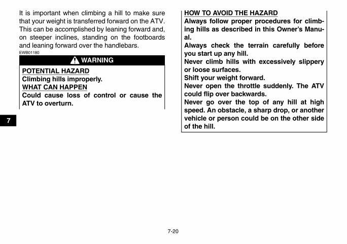
7-20
7
It is important when climbing a hill to make surethat your weight is transferred forward on the ATV.This can be accomplished by leaning forward and,on steeper inclines, standing on the footboardsand leaning forward over the handlebars.
WARNINGEWB01180
POTENTIAL HAZARDClimbing hills improperly.WHAT CAN HAPPENCould cause loss of control or cause theATV to overturn.
HOW TO AVOID THE HAZARDAlways follow proper procedures for climb-ing hills as described in this Owner’s Manu-al.Always check the terrain carefully beforeyou start up any hill.Never climb hills with excessively slipperyor loose surfaces.Shift your weight forward.Never open the throttle suddenly. The ATVcould flip over backwards.Never go over the top of any hill at highspeed. An obstacle, a sharp drop, or anothervehicle or person could be on the other sideof the hill.
U17S10E0.book Page 20 Friday, July 6, 2007 1:37 PM

7-21
7
U17S10E0.book Page 21 Friday, July 6, 2007 1:37 PM

7-22
7
If you are climbing a hill and you find that you havenot properly judged your ability to make it to thetop, you should turn the ATV around while you stillhave forward motion (provided you have the roomto do so) and go down the hill.
WARNINGEWB01190
If your ATV has stalled or stopped and you believeyou can continue up the hill, restart carefully tomake sure you do not lift the front wheels whichcould cause you to lose control. If you are unableto continue up the hill, dismount the ATV on the up-hill side. Physically turn the ATV around and thendescend the hill.
POTENTIAL HAZARDImproperly crossing hills or turning on hills.WHAT CAN HAPPENCould cause loss of control or cause theATV to overturn.HOW TO AVOID THE HAZARDNever attempt to turn the ATV around on anyhill until you have mastered the turning tech-nique as described in the Owner’s Manualon level ground. Be very careful when turn-ing on any hill.Avoid crossing the side of a steep hill if pos-sible.
When crossing the side of a hill:Always follow proper procedures as de-scribed in the Owner’s Manual.Avoid hills with excessively slippery or loosesurfaces.Shift your weight to the uphill side of theATV.
U17S10E0.book Page 22 Friday, July 6, 2007 1:37 PM
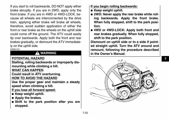
7-23
7
If you start to roll backwards, DO NOT apply eitherbrake abruptly. If you are in 2WD, apply only thefront brake. If you are in 4WD or 4WD-LOCK, be-cause all wheels are interconnected by the drivetrain, applying either brake will brake all wheels,therefore, avoid sudden application of either thefront or rear brake as the wheels on the uphill sidecould come off the ground. The ATV could easilytip over backwards. Apply both the front and rearbrakes gradually, or dismount the ATV immediate-ly on the uphill side.
WARNINGEWB01321
POTENTIAL HAZARDStalling, rolling backwards or improperly dis-mounting while climbing a hill.WHAT CAN HAPPENCould result in ATV overturning.HOW TO AVOID THE HAZARDUse the proper gear and maintain a steadyspeed when climbing a hill.If you lose all forward speed:� Keep weight uphill.� Apply the brakes.� Shift to the park position after you are
stopped.
If you begin rolling backwards:� Keep weight uphill.� 2WD: Never apply the rear brake while roll-
ing backwards. Apply the front brake.When fully stopped, shift to the park posi-tion.
� 4WD or 4WD-LOCK: Apply both front andrear brakes gradually. When fully stopped,shift to the park position.
Dismount on uphill side or to a side if point-ed straight uphill. Turn the ATV around andremount, following the procedure describedin the Owner’s Manual.
U17S10E0.book Page 23 Friday, July 6, 2007 1:37 PM

7-24
7
RIDING DOWNHILLWhen riding your ATV downhill, shift your weightas far to the rear and uphill side of the ATV as pos-sible. Move back on the seat and sit with your armsstraight. Engine compression will do most of thebraking for you. For maximum engine compres-sion braking effect, select the low-range positionand change to 4WD or 4WD-LOCK before begin-ning to descend the hill. Improper braking maycause a loss of traction.Use caution while descending a hill with loose orslippery surfaces. Braking ability and traction maybe adversely affected by these surfaces. Improperbraking may also cause a loss of traction.When this ATV is in 4WD or 4WD-LOCK, allwheels (front and rear) are interconnected by thedrive train. This means that applying either thefront brake or the rear brake will brake all wheels.When descending hills, using either brake lever orthe brake pedal will brake the wheels on the down-hill side. Avoid sudden application of either thefront or rear brake because the wheels on the up-hill side could come off the ground. Apply both thefront and rear brakes gradually.
Whenever possible, ride your ATV straight down-hill. Avoid sharp angles which could allow the ATVto tip or roll over. Carefully choose your path andride no faster than you will be able to react to ob-stacles which may appear.
WARNINGEWB01130
POTENTIAL HAZARDGoing down a hill improperly.WHAT CAN HAPPENCould cause loss of control or cause theATV to overturn.HOW TO AVOID THE HAZARDAlways follow proper procedures for goingdown hills as described in this Owner’s Man-ual.Note: a special technique is required whenbraking as you go down a hill.Always check the terrain carefully beforeyou start down any hill.Shift your weight backward.Never go down a hill at high speed.Avoid going down a hill at an angle thatwould cause the ATV to lean sharply to oneside. Go straight down the hill where possi-ble.
U17S10E0.book Page 24 Friday, July 6, 2007 1:37 PM

7-25
7
U17S10E0.book Page 25 Friday, July 6, 2007 1:37 PM

7-26
7
CROSSING A SLOPETraversing a sloping surface on your ATV requiresyou to properly position your weight to maintainproper balance. Be sure that you have learned thebasic riding skills on flat ground before attemptingto cross a sloping surface. Avoid slopes with slip-pery surfaces or rough terrain that may upset yourbalance.As you travel across a slope, lean your body in theuphill direction. It may be necessary to correct thesteering when riding on loose surfaces by pointingthe front wheels slightly uphill. When riding onslopes, be sure not to make sharp turns either upor down hill.If your ATV does begin to tip over, gradually steerin the downhill direction if there are no obstacles inyour path. As you regain proper balance, graduallysteer again in the direction you wish to travel.
WARNINGEWB01141
POTENTIAL HAZARDImproperly crossing hills or turning on hills.WHAT CAN HAPPENCould cause loss of control or cause theATV to overturn.
HOW TO AVOID THE HAZARDNever attempt to turn the ATV around on anyhill until you have mastered the turning tech-nique as described in the Owner’s Manualon level ground. Be very careful when turn-ing on any hill. Avoid crossing the side of asteep hill if possible.When crossing the side of a hill:Always follow proper procedures as de-scribed in the Owner’s Manual.Avoid hills with excessively slippery or loosesurfaces.Shift your weight to the uphill side of theATV.
U17S10E0.book Page 26 Friday, July 6, 2007 1:37 PM

7-27
7
U17S10E0.book Page 27 Friday, July 6, 2007 1:37 PM

7-28
7
CROSSING THROUGH SHALLOW WATERThe ATV can be used to cross slow moving, shal-low water of up to a maximum of 35 cm (14 in) indepth. Before entering the water, choose your pathcarefully. Enter where there is no sharp drop off,and avoid rocks or other obstacles which may beslippery or upset the ATV. Drive slowly and care-fully.
WARNINGEWB01150
Test your brakes after leaving the water. Do notcontinue to ride your ATV without verifying that youhave regained proper braking ability.
POTENTIAL HAZARDOperating this ATV through deep or fastflowing water.WHAT CAN HAPPENTires may float, causing loss of traction andloss of control, which could lead to an acci-dent.HOW TO AVOID THE HAZARDNever operate this ATV in fast flowing wateror in water deeper than that specified in yourOwner’s Manual.Remember that wet brakes may have re-duced stopping ability. Test your brakes af-ter leaving water. If necessary, apply themseveral times to let friction dry out the lin-ings.
U17S10E0.book Page 28 Friday, July 6, 2007 1:37 PM

7-29
7CAUTION:ECB00280
After riding your ATV in water, be sure to drainthe trapped water by removing the check hoseat the bottom of the air filter case, the V-beltcooling duct check hose, the drive select leverbox check hose and the storage compartmentcheck hose. Also, remove the V-belt case drainplug to drain any water that may have accumu-lated. Wash the ATV in fresh water if it has beenoperated in salt water or muddy conditions.
1. Air filter case check hose
1. V-belt cooling duct check hose (left front side of ATV)
U17S10E0.book Page 29 Friday, July 6, 2007 1:37 PM

7-30
7 RIDING OVER ROUGH TERRAINRiding over rough terrain should be done with cau-tion. Look out for obstacles which could causedamage to the ATV or could lead to an upset or ac-cident. Be sure to keep your feet firmly mounted onthe footboards at all times. Avoid jumping the ATVas loss of control and damage to the ATV may re-sult.
WARNINGEWB01160
1. Drive select lever box check hose
1. Storage compartment check hose
1. V-belt case drain plug
POTENTIAL HAZARDImproperly operating over obstacles.
U17S10E0.book Page 30 Friday, July 6, 2007 1:37 PM

7-31
7
SLIDING AND SKIDDINGCare should be used when riding on loose or slip-pery surfaces since the ATV may slide. If unex-pected and uncorrected, sliding could lead to anaccident.To reduce the tendency for the front wheels to slidein loose or slippery conditions, positioning yourweight over the front wheels will sometimes help.
WHAT CAN HAPPENCould cause loss of control or a collision.Could cause the ATV to overturn.HOW TO AVOID THE HAZARDBefore operating in a new area, check for ob-stacles.Never attempt to ride over large obstacles,such as large rocks or fallen trees. Whenyou go over obstacles, always follow properprocedures as described in the Owner’sManual.
U17S10E0.book Page 31 Friday, July 6, 2007 1:37 PM

7-32
7
If the rear wheels of your ATV start to slide side-ways, control can usually be regained (if there isroom to do so) by steering in the direction of theslide. Applying the brakes or accelerating is notrecommended until you have corrected the slide.
With practice, over a period of time, skill at con-trolled sliding can be developed. The terrainshould be chosen carefully before attempting suchmaneuvers, since both stability and control are re-duced. Bear in mind that sliding maneuvers shouldalways be avoided on extremely slippery surfacessuch as ice, since all control may be lost.
WARNINGEWB01170
WHAT TO DO IF...This section is designed to be a reference guideonly. Be sure to read each section on riding tech-niques completely.
POTENTIAL HAZARDSkidding or sliding improperly.WHAT CAN HAPPENYou may lose control of this ATV. You mayalso regain traction unexpectedly, whichmay cause the ATV to overturn.HOW TO AVOID THE HAZARDLearn to safely control skidding or sliding bypracticing at low speeds and on level,smooth terrain.On extremely slippery surfaces, such as ice,go slowly and be very cautious in order toreduce the chance of skidding or sliding outof control.
U17S10E0.book Page 32 Friday, July 6, 2007 1:37 PM

7-33
7
WHAT TO DO...� If your ATV doesn’t turn when you want it to:
Bring the ATV to a stop and practice the turningmaneuvers again. Be sure you are putting yourweight on the footboard to the outside of theturn. Position your weight over the front wheelsfor better control. (See page 7-17.)
� If your ATV begins to tip while turning:Lean more into the turn to regain balance. If nec-essary, gradually let off the throttle and/or steerto the outside of the turn. (See page 7-17.)
� If your ATV starts to slide sideways:Steer in the direction of the slide if you have theroom. Applying the brakes or accelerating is notrecommended until you have corrected theslide. (See page 7-31.)
� If your ATV can’t make it up a hill you are tryingto climb:Turn the ATV around if you still have forwardspeed. If not, stop, dismount on the uphill side ofthe ATV and physically turn the ATV around. Ifthe ATV starts to slip backwards, DO NOT USETHE REAR BRAKE IF THE ATV IS IN 2WD –the ATV may tip over on top of you. Dismountthe ATV on the uphill side. (See page 7-18.)
� If your ATV is traversing a sloping surface:Be sure to ride with your weight positioned to-wards the uphill side of the ATV to maintainproper balance. If the ATV starts to tip, steerdown the hill (if there are no obstacles in yourway) to regain balance. If you discover that theATV is going to tip over, dismount on the uphillside. (See page 7-18.)
� If your ATV encounters shallow water:Ride slowly and carefully through slow movingwater, watching for obstacles. Be sure to let wa-ter drain from the ATV and CHECK YOURBRAKES FOR PROPER OPERATION whenyou come out of the water. Do not continue toride your ATV until you have regained adequatebraking ability. (See page 7-28.)
WARNINGEWB00010
Indicates a potential hazard that could result inserious injury or death.
U17S10E0.book Page 33 Friday, July 6, 2007 1:37 PM

8-1
8
EBU21647
PERIODIC MAINTENANCE AND MINOR REPAIREBU21660
Safety is an obligation of the owner. Periodic in-spection, adjustment and lubrication will keep yourATV in the safest and best operating conditionpossible. The most important points of inspection,adjustment, and lubrication are explained on thefollowing pages.The intervals given in the periodic maintenanceand lubrication chart should be considered as ageneral guide under normal riding conditions.However, DEPENDING ON THE WEATHER,TERRAIN, GEOGRAPHICAL LOCATION, ANDINDIVIDUAL USE, THE MAINTENANCE INTER-VALS MAY NEED TO BE SHORTENED.
WARNINGEWB01820
EBU21720
Owner’s manual and tool kit Be sure to put this owner’s manual in the plasticbag and always carry it on the bottom of the seatas shown. Put the owner’s tool kit and low-pres-sure tire gauge under the seat.
POTENTIAL HAZARDServicing an engine while it is running.WHAT CAN HAPPENMoving parts can catch clothing or parts ofthe body, causing injury.Electrical components can cause shocks orstart fires.
HOW TO AVOID THE HAZARDTurn off the engine when performing mainte-nance unless otherwise specified. Have aYamaha dealer perform the service if you arenot familiar with maintenance work.
U17S10E0.book Page 1 Friday, July 6, 2007 1:37 PM

8-2
8The service information included in this manualand the tools provided in the owner’s tool kit are in-tended to assist you in the performance of preven-tive maintenance and minor repairs. However,additional tools such as a torque wrench may benecessary to perform certain maintenance workcorrectly.
NOTE:If you do not have the tools or experience requiredfor a particular job, have a Yamaha dealer performit for you.
WARNINGEWB01830
1. Owner’s manual2. Owner’s tool kit3. Low-pressure tire gauge
POTENTIAL HAZARDOperating this ATV with improper modifica-tions.WHAT CAN HAPPENImproper installation of accessories or mod-ification of this ATV may cause changes inhandling which in some situations couldlead to an accident.HOW TO AVOID THE HAZARDNever modify this ATV through improper in-stallation or use of accessories. All partsand accessories added to this ATV shouldbe genuine Yamaha or equivalent compo-nents designed for use on this ATV andshould be installed and used according toinstructions. If you have questions, consultan authorized Yamaha ATV dealer.
U17S10E0.book Page 2 Friday, July 6, 2007 1:37 PM

8-3
8
EBU21742
Periodic maintenance chart for the emission control system
NOTE:� For ATVs not equipped with an odometer or an hour meter, follow the month maintenance intervals.� For ATVs equipped with an odometer or an hour meter, follow the km (mi) or hours maintenance inter-
vals. However, keep in mind that if the ATV isn’t used for a long period of time, the month maintenanceintervals should be followed.
� Items marked with an asterisk should be performed by a Yamaha dealer as they require special tools,data and technical skills.
NO. ITEM CHECK OR MAINTENANCE JOB
INITIAL EVERY
Whichev-er comes
first
month 1 3 6 6 12
km (mi)
320 (200)
1300 (800)
2500 (1600)
2500 (1600)
5000 (3200)
hours 20 80 160 160 320
1 * Fuel line • Check fuel hoses for cracks or other damage, and replace if necessary. √ √ √
2 Spark plug • Check condition and clean, regap, or replace if necessary. √ √ √ √ √
3 * Valves • Check valve clearance and adjust if necessary. √ √ √ √
4 * Carburetor
• Check starter (choke) operation and correct if nec-essary.
• Check engine idling speed and adjust if neces-sary.
√ √ √ √
5 * Crankcase breather system
• Check breather hose for cracks or other damage, and replace if necessary. √ √ √
U17S10E0.book Page 3 Friday, July 6, 2007 1:37 PM

8-4
8
6 * Exhaust system
• Check for leakage and replace gasket(s) if neces-sary.
• Check for looseness and tighten all screw clamps and joints if necessary.
√ √ √
7 Spark arrester • Clean. √ √ √
NO. ITEM CHECK OR MAINTENANCE JOB
INITIAL EVERY
Whichev-er comes
first
month 1 3 6 6 12
km (mi)
320 (200)
1300 (800)
2500 (1600)
2500 (1600)
5000 (3200)
hours 20 80 160 160 320
U17S10E0.book Page 4 Friday, July 6, 2007 1:37 PM

8-5
8
EBU21864
General maintenance and lubrication chart
NO. ITEM CHECK OR MAINTENANCE JOB
INITIAL EVERY
Whichev-er comes
first
month 1 3 6 6 12
km (mi)
320 (200)
1300 (800)
2500 (1600)
2500 (1600)
5000 (3200)
hours 20 80 160 160 320
1 Air filter element • Clean and replace if necessary. Every 20–40 hours (more often in wet or dusty areas)
2 * Front brake
• Check operation and correct if necessary.• Check fluid level and ATV for fluid leakage, and
correct if necessary.√ √ √ √ √
• Replace brake pads. Whenever worn to the limit
3 * Rear brake
• Check operation and correct if necessary.• Check brake lever and pedal free play, and adjust
if necessary.√ √ √ √ √
• Replace brake friction plates. Whenever worn to the limit
4 * Brake hoses• Check for cracks or other damage, and replace if
necessary. √ √ √ √
• Replace. Every 4 years
5 * Wheels • Check runout and for damage, and replace if nec-essary. √ √ √ √
6 * Tires
• Check tread depth and for damage, and replace if necessary.
• Check air pressure and balance, and correct if necessary.
√ √ √ √
7 * Wheel hub bearings • Check for looseness or damage, and replace if necessary. √ √ √ √
8 * V-belt • Check for wear, cracks or other damage, and re-place if necessary. √ √ √ √
U17S10E0.book Page 5 Friday, July 6, 2007 1:37 PM
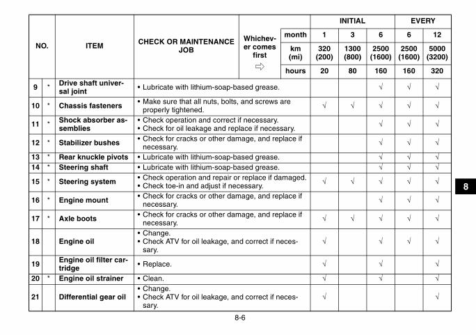
8-6
8
9 * Drive shaft univer-sal joint • Lubricate with lithium-soap-based grease. √ √ √
10 * Chassis fasteners • Make sure that all nuts, bolts, and screws are properly tightened. √ √ √ √ √
11 * Shock absorber as-semblies
• Check operation and correct if necessary.• Check for oil leakage and replace if necessary. √ √ √
12 * Stabilizer bushes • Check for cracks or other damage, and replace if necessary. √ √ √
13 * Rear knuckle pivots • Lubricate with lithium-soap-based grease. √ √ √14 * Steering shaft • Lubricate with lithium-soap-based grease. √ √ √
15 * Steering system • Check operation and repair or replace if damaged.• Check toe-in and adjust if necessary. √ √ √ √ √
16 * Engine mount • Check for cracks or other damage, and replace if necessary. √ √ √
17 * Axle boots • Check for cracks or other damage, and replace if necessary. √ √ √ √ √
18 Engine oil• Change.• Check ATV for oil leakage, and correct if neces-
sary.√ √ √ √
19 Engine oil filter car-tridge • Replace. √ √ √
20 * Engine oil strainer • Clean. √ √ √
21 Differential gear oil• Change.• Check ATV for oil leakage, and correct if neces-
sary.√ √
NO. ITEM CHECK OR MAINTENANCE JOB
INITIAL EVERY
Whichev-er comes
first
month 1 3 6 6 12
km (mi)
320 (200)
1300 (800)
2500 (1600)
2500 (1600)
5000 (3200)
hours 20 80 160 160 320
U17S10E0.book Page 6 Friday, July 6, 2007 1:37 PM

8-7
8
EBU28390
NOTE:� The air filter needs more frequent service if you are riding in unusually wet or dusty areas.
22 Final gear oil• Change.• Check ATV for oil leakage, and correct if neces-
sary.√ √ √
23 Cooling system• Check coolant level and ATV for coolant leakage,
and correct if necessary. √ √ √ √ √
• Replace coolant. Every 2 years
24 * Moving parts and cables • Lubricate. √ √ √ √
25 * Drive select lever safety system cable
• Check operation and adjust or replace if neces-sary. √ √ √
26 * Throttle lever hous-ing and cable
• Check operation and correct if necessary.• Check throttle cable free play and adjust if neces-
sary.• Lubricate throttle lever housing and cable.
√ √ √ √ √
27 * Front and rear brake switches • Check operation and correct if necessary. √ √ √ √ √
28 * Lights and switches • Check operation and correct if necessary.• Adjust headlight beams. √ √ √ √ √
NO. ITEM CHECK OR MAINTENANCE JOB
INITIAL EVERY
Whichev-er comes
first
month 1 3 6 6 12
km (mi)
320 (200)
1300 (800)
2500 (1600)
2500 (1600)
5000 (3200)
hours 20 80 160 160 320
U17S10E0.book Page 7 Friday, July 6, 2007 1:37 PM

8-8
8
� Hydraulic brake service• Regularly check and, if necessary, correct the brake fluid level.• Every two years replace the internal components of the brake master cylinder and calipers, and change
the brake fluid.• Replace the brake hoses every four years and if cracked or damaged.
U17S10E0.book Page 8 Friday, July 6, 2007 1:37 PM

8-9
8
WARNINGEWB00010
Indicates a potential hazard that could result inserious injury or death.
EBU23090
Removing and installing panels The panels shown need to be removed to performsome of the maintenance jobs described in thischapter. Refer to this section each time a panelneeds to be removed and installed.
EBU27600
Panels A and D
To remove one of the panels1. Remove the seat. (See page 4-19.)2. Pull outward on the areas shown, and then
pull upward as shown.
1. Panel A2. Panel B
1. Panel C2. Panel D3. Panel E4. Panel F
U17S10E0.book Page 9 Friday, July 6, 2007 1:37 PM

8-10
8
To install one of the panels1. Place the panel in its original position.
U17S10E0.book Page 10 Friday, July 6, 2007 1:37 PM

8-11
8
2. Install the seat.
Panel B
To remove the panelRemove the bolt, and then take the panel off.
To install the panelPlace the panel in the original position and installthe bolt.
CAUTION:ECB00380
When installing the panel, be sure not to pinchthe cables or wires.
1. Panel B2. Bolt
U17S10E0.book Page 11 Friday, July 6, 2007 1:37 PM

8-12
8
Panel C
To remove the panel1. Remove the carrier top bolts.
2. Remove the carrier bolts under the fenders,and then take the carrier off.
3. Remove the quick fastener screws, and thenpull the panel upward to remove it.
1. Carrier bolt (top)
1. Carrier bolt (under the fenders)
U17S10E0.book Page 12 Friday, July 6, 2007 1:37 PM

8-13
8
To install the panel1. Place the panel in the original position, and
then install the quick fastener screws.2. Place the carrier in the original position, and
then install the carrier bolts under the fenders.3. Install the carrier top bolts, and then tighten all
bolts to the specified torques.
Panel E
To remove the panelRemove the bolts, and then take the panel off.
To install the panelPlace the panel in the original position and installthe bolts.
Panel F
To remove the panelPull outward on the areas shown.
1. Quick fastener screw2. Panel C
Tightening torques:Carrier bolt (top):
34 Nm (3.4 m·kgf, 24 ft·lbf)Carrier bolt (under fenders):
7 Nm (0.7 m·kgf, 5.1 ft·lbf)
1. Panel E2. Bolt
U17S10E0.book Page 13 Friday, July 6, 2007 1:37 PM

8-14
8
To install the panelPlace the panel in its original position.
EBU23221
Checking the spark plug The spark plug is an important engine component,which is easy to check. Since heat and depositswill cause any spark plug to slowly erode, the sparkplug should be removed and checked in accor-dance with the periodic maintenance and lubrica-tion chart. In addition, the condition of the sparkplug can reveal the condition of the engine.
To remove the spark plug1. Remove panel A. (See page 8-9.)2. Remove the spark plug cap.1. Panel F
1. Spark plug cap
U17S10E0.book Page 14 Friday, July 6, 2007 1:37 PM

8-15
8
3. Remove the spark plug as shown, with thespark plug wrench included in the owner’s toolkit.
To check the spark plug1. Check that the porcelain insulator around the
center electrode of the spark plug is a medi-um-to-light tan (the ideal color when the ATVis ridden normally).
NOTE:If the spark plug shows a distinctly different color,the engine could be operating improperly. Do notattempt to diagnose such problems yourself. In-stead, have a Yamaha dealer check the ATV.
2. Check the spark plug for electrode erosionand excessive carbon or other deposits, andreplace it if necessary.
To install the spark plug1. Measure the spark plug gap with a wire thick-
ness gauge and, if necessary, adjust the gapto specification.
1. Spark plug wrench
Specified spark plug:NGK/DR8EA
Spark plug gap:0.6–0.7 mm (0.024–0.028 in)
U17S10E0.book Page 15 Friday, July 6, 2007 1:37 PM

8-16
8
2. Clean the surface of the spark plug gasketand its mating surface, and then wipe off anygrime from the spark plug threads.
3. Install the spark plug with the spark plugwrench, and then tighten it to the specifiedtorque.
NOTE:If a torque wrench is not available when installinga spark plug, a good estimate of the correct torqueis 1/4–1/2 turn past finger tight. However, the sparkplug should be tightened to the specified torque assoon as possible.
4. Install the spark plug cap.5. Install the panel.
EBU23325
Engine oil and oil filter cartridge The engine oil level should be checked beforeeach ride. In addition, the oil must be changed andthe oil filter cartridge replaced at the intervals spec-ified in the periodic maintenance and lubricationchart.
To check the engine oil level1. Remove panel F. (See page 8-9.)2. Place the ATV on a level surface.3. Check the engine oil level on a cold engine.
1. Spark plug gap
Tightening torque:Spark plug:
17.5 Nm (1.75 m·kgf, 12.7 ft·lbf)
U17S10E0.book Page 16 Friday, July 6, 2007 1:37 PM

8-17
8
NOTE:If the engine was started before checking the oillevel, be sure to warm up the engine sufficiently,and then wait at least ten minutes until the oil set-tles for an accurate reading.
4. Remove the engine oil filler cap, and thenwipe the dipstick off with a clean rag.
5. Insert the dipstick into the filler hole (withoutscrewing it in), and then remove it again tocheck the oil level.
NOTE:The engine oil should be between the minimumand maximum level marks.
6. If the engine oil is at or below the minimumlevel mark, add sufficient oil of the recom-mended type to raise it to the correct level.
7. Insert the dipstick into the oil filler hole, andthen tighten the engine oil filler cap.
8. Install the panel.
1. Engine oil filler cap
1. Dipstick2. Maximum level mark3. Minimum level mark
U17S10E0.book Page 17 Friday, July 6, 2007 1:37 PM

8-18
8
To change the engine oil (with or without oil fil-ter cartridge replacement)
1. Remove panel F. (See page 8-9.)2. Place the ATV on a level surface.3. Start the engine, warm it up for several min-
utes, and then turn it off.4. Place an oil pan under the engine to collect
the used oil.5. Remove the engine oil filler cap, and then re-
move the engine oil drain bolt to drain the oilfrom the crankcase.
NOTE:Skip steps 6–10 if the oil filter cartridge is not beingreplaced.
6. Remove panels D and E. (See page 8-9.)7. Remove the oil filter cartridge with an oil filter
wrench.
1. Engine oil drain bolt
1. Oil filter cartridge
U17S10E0.book Page 18 Friday, July 6, 2007 1:37 PM
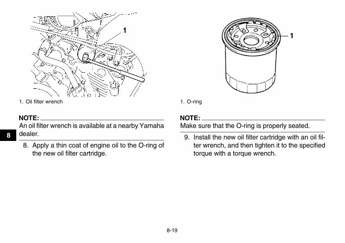
8-19
8
NOTE:An oil filter wrench is available at a nearby Yamahadealer.
8. Apply a thin coat of engine oil to the O-ring ofthe new oil filter cartridge.
NOTE:Make sure that the O-ring is properly seated.
9. Install the new oil filter cartridge with an oil fil-ter wrench, and then tighten it to the specifiedtorque with a torque wrench.
1. Oil filter wrench 1. O-ring
U17S10E0.book Page 19 Friday, July 6, 2007 1:37 PM

8-20
8
10. Install panels E and D.11. Install the engine oil drain bolt, and then tight-
en it to the specified torque.
12. Add the specified amount of the recommend-ed engine oil, and then install and tighten theengine oil filler cap.
NOTE:Be sure to wipe off spilled oil on any parts after theengine and exhaust system have cooled down.
CAUTION:ECB00300
� In order to prevent clutch slippage (since theengine oil also lubricates the clutch), do notmix any chemical additives. Do not use oilswith a diesel specification of “CD” or oils ofa higher quality than specified. In addition,do not use oils labeled “ENERGY CONSERV-ING II” or higher.
1. Torque wrench
Tightening torque:Oil filter cartridge:
17 Nm (1.7 m·kgf, 12 ft·lbf)
Tightening torque:Engine oil drain bolt:
23 Nm (2.3 m·kgf, 17 ft·lbf)
Recommended oil:See page 10-1.
Oil quantity:Without oil filter cartridge replacement:
2.30 L (2.43 US qt) (2.02 Imp.qt)With oil filter cartridge replacement:
2.40 L (2.54 US qt) (2.11 Imp.qt)
U17S10E0.book Page 20 Friday, July 6, 2007 1:37 PM

8-21
8
� Make sure that no foreign material enters thecrankcase.
13. Start the engine, and then let it idle for severalminutes while checking it for oil leakage. If oilis leaking, immediately turn the engine off andcheck for the cause.
14. Turn the engine off, wait at least ten minutes,and then check the oil level and correct it ifnecessary.
15. Install panel F.
EBU28570
Final gear oil The final gear case must be checked for oil leak-age before each ride. If any leakage is found, havea Yamaha dealer check and repair the ATV. In ad-dition, the final gear oil level must be checked andthe oil changed as follows at the intervals specifiedin the periodic maintenance and lubrication chart.
To check the final gear oil level1. Place the ATV on a level surface.
NOTE:The final gear oil level must be checked on a coldengine.
2. Remove the final gear oil filler bolt, and thencheck the oil level in the final gear case.
NOTE:The oil level should be at the brim of the filler hole.
3. If the oil is below the brim of the filler hole, addsufficient oil of the recommended type to raiseit to the correct level.
4. Install the oil filler bolt, and then tighten it to thespecified torque.
1. Final gear oil filler bolt2. Correct oil level3. Final gear oil
U17S10E0.book Page 21 Friday, July 6, 2007 1:37 PM

8-22
8
To change the final gear oil1. Remove the engine guard and the final gear
case guard by removing the bolts.
2. Place the ATV on a level surface.3. Place an oil pan under the final gear case to
collect the used oil.
4. Remove the final gear oil filler bolt and the fi-nal gear oil drain bolt to drain the oil from thefinal gear case.
5. Install the drain bolt, and then tighten it to thespecified torque.
6. Add the recommended final gear oil to thebrim of the filler hole as shown.
Tightening torque:Final gear oil filler bolt:
24 Nm (2.4 m·kgf, 17 ft·lbf)
1. Engine guard2. Final gear case guard3. Bolt
1. Final gear oil drain bolt
Tightening torque:Final gear oil drain bolt:
24 Nm (2.4 m·kgf, 17 ft·lbf)
U17S10E0.book Page 22 Friday, July 6, 2007 1:37 PM

8-23
8
NOTE:If the recommended oil is not available, SAE80W-90 API GL-5 Hypoid gear oil may be used instead.However, when using this oil, noise from the finalgear case may occur when applying the rearbrake.
CAUTION:ECB00420
Be sure no foreign material enters the finalgear case.
7. Install the oil filler bolt, and then tighten it to thespecified torque.
8. Check the final gear case for oil leakage. If oilis leaking, check for the cause.
9. Install the engine guard and the final gearcase guard by installing the bolts, and thentightening them to the specified torques.
1. Final gear oil filler bolt2. Correct oil level3. Final gear oil
Recommended final gear oil:See page 10-1.
Tightening torque:Final gear oil filler bolt:
24 Nm (2.4 m·kgf, 17 ft·lbf)
Tightening torques:Engine guard bolt:
7 Nm (0.7 m·kgf, 5.1 ft·lbf)Final gear case guard bolt:
7 Nm (0.7 m·kgf, 5.1 ft·lbf)
U17S10E0.book Page 23 Friday, July 6, 2007 1:37 PM

8-24
8
EBU23421
Differential gear oil The differential gear case must be checked for oilleakage before each ride. If any leakage is found,have a Yamaha dealer check and repair the ATV.In addition, the differential gear oil level must bechecked and the oil changed as follows at the in-tervals specified in the periodic maintenance andlubrication chart.
To check the differential gear oil level1. Place the ATV on a level surface.
NOTE:The differential gear oil level must be checked ona cold engine.
2. Remove the differential gear oil filler bolt, andthen check the oil level in the differential gearcase.
NOTE:The oil level should be at the brim of the filler hole.
3. If the oil is below the brim of the filler hole, addsufficient oil of the recommended type to raiseit to the correct level.
4. Install the oil filler bolt, and then tighten it to thespecified torque.
1. Differential gear oil2. Differential gear oil filler bolt3. Correct oil level
Tightening torque:Differential gear oil filler bolt:
23 Nm (2.3 m·kgf, 17 ft·lbf)
U17S10E0.book Page 24 Friday, July 6, 2007 1:37 PM

8-25
8
To change the differential gear oil1. Place the ATV on a level surface.2. Place an oil pan under the differential gear
case to collect the used oil.3. Remove the differential gear oil filler bolt and
the differential gear oil drain bolt to drain theoil from the differential gear case.
4. Install the drain bolt, and then tighten it to thespecified torque.
5. Add the recommended differential gear oil tothe brim of the filler hole as shown.
CAUTION:ECB00410
Be sure no foreign material enters the differen-tial gear case.
6. Install the oil filler bolt, and then tighten it to thespecified torque.
1. Differential gear oil drain bolt
Tightening torque:Differential gear oil drain bolt:
10 Nm (1.0 m·kgf, 7.2 ft·lbf)
1. Differential gear oil2. Differential gear oil filler bolt3. Correct oil level
Recommended differential gear oil:See page 10-1.
U17S10E0.book Page 25 Friday, July 6, 2007 1:37 PM

8-26
8
7. Check the differential gear case for oil leak-age. If oil is leaking, check for the cause.
EBU23470
Coolant The coolant level should be checked before eachride. In addition, the coolant must be changed atthe intervals specified in the periodic maintenanceand lubrication chart.
EBU27122
To check the coolant level1. Place the ATV on a level surface.
NOTE:The coolant level must be checked on a cold en-gine since the level varies with engine tempera-ture.
2. Check the coolant level in the coolant reser-voir.
NOTE:The coolant should be between the minimum andmaximum level marks.
3. If the coolant is at or below the minimum levelmark, remove panel D. (See page 8-9.)
4. Remove the reservoir cap, add coolant or dis-tilled water to the maximum level mark, installthe reservoir cap, and then install the panel.
Tightening torque:Differential gear oil filler bolt:
23 Nm (2.3 m·kgf, 17 ft·lbf)
1. Coolant reservoir cap2. Maximum level mark3. Minimum level mark
U17S10E0.book Page 26 Friday, July 6, 2007 1:37 PM

8-27
8
CAUTION:ECB00401
� If coolant is not available, use distilled wateror soft tap water instead. Do not use hard wa-ter or salt water since it is harmful to the en-gine.
� If water has been used instead of coolant, re-place it with coolant as soon as possible,otherwise the cooling system will not be pro-tected against frost and corrosion.
� If water has been added to the coolant, havea Yamaha dealer check the antifreeze con-tent of the coolant as soon as possible, oth-erwise the effectiveness of the coolant willbe reduced.
NOTE:� The radiator fan is automatically switched on or
off according to the coolant temperature in theradiator.
� If the engine overheats, see page 8-61 for fur-ther instructions.
EBU23592
To change the coolant
WARNINGEWB01880
1. Place the ATV on a level surface.2. Remove panels E and F. (See page 8-9.)3. Place a container under the engine, and then
remove the coolant drain bolt. (Use a troughor a similar object as shown to prevent coolantfrom spilling on the footrest.)
Coolant reservoir capacity (up to the maximum level mark):
0.25 L (0.26 US qt) (0.22 Imp.qt)
POTENTIAL HAZARDRemoving the radiator cap when the engineand radiator are still hot.WHAT CAN HAPPENYou could be burned by hot fluid and steamblown out under pressure.HOW TO AVOID THE HAZARDWait for the engine to cool before removingthe radiator cap. Always place a thick ragover the cap. Allow any remaining pressureto escape before completely removing thecap.
U17S10E0.book Page 27 Friday, July 6, 2007 1:37 PM

8-28
8
4. Remove the front carrier and panel C. (Seepage 8-9.)
5. Remove the radiator cap.
6. Remove panel D. (See page 8-9.)7. Remove the coolant reservoir cap.8. Disconnect the hose on the coolant reservoir
side, and then drain the coolant from the cool-ant reservoir.
1. Coolant drain bolt
1. Trough
1. Radiator cap
U17S10E0.book Page 28 Friday, July 6, 2007 1:37 PM

8-29
8
9. After draining the coolant, thoroughly flush thecooling system with clean tap water.
10. Replace the coolant drain bolt washer if it isdamaged, install the coolant drain bolt, andthen tighten it to the specified torque.
11. Connect the coolant reservoir hose.12. Pour the recommended coolant into the reser-
voir to the maximum level mark, and then in-stall the reservoir cap.
13. Pour the recommended coolant into the radia-tor until it is full.
CAUTION:ECB00401
� If coolant is not available, use distilled wateror soft tap water instead. Do not use hard wa-ter or salt water since it is harmful to the en-gine.
� If water has been used instead of coolant, re-place it with coolant as soon as possible,otherwise the cooling system will not be pro-tected against frost and corrosion.
1. Coolant reservoir hose
Tightening torque:Coolant drain bolt:
10 Nm (1.0 m·kgf, 7.2 ft·lbf)
Antifreeze/water mixture ratio:1:1
Recommended antifreeze:High-quality ethylene glycol antifreeze con-taining corrosion inhibitors for aluminum en-gines
Coolant quantity:Radiator capacity (including all routes):
1.30 L (1.37 US qt) (1.14 Imp.qt)Coolant reservoir capacity (up to the maxi-mum level mark):
0.25 L (0.26 US qt) (0.22 Imp.qt)
U17S10E0.book Page 29 Friday, July 6, 2007 1:37 PM

8-30
8
� If water has been added to the coolant, havea Yamaha dealer check the antifreeze con-tent of the coolant as soon as possible, oth-erwise the effectiveness of the coolant willbe reduced.
14. Install the radiator cap, start the engine, let itidle for several minutes, and then turn it off.
15. Remove the radiator cap to check the coolantlevel in the radiator. If it is low, add sufficientcoolant until it reaches the top of the radiator,and then install the radiator cap.
16. Start the engine, and then check for coolantleakage.
NOTE:If any leakage is found, have a Yamaha dealercheck the cooling system.
17. Install the panels and the front carrier.
EBU23631
Cleaning the air filter element The air filter element should be cleaned at the in-tervals specified in the periodic maintenance andlubrication chart. Clean the air filter element morefrequently if you are riding in unusually wet or dustyareas.
NOTE:There is a check hose at the bottom of the air filtercase. If dust or water collects in this hose, emptythe hose and clean the air filter element and air fil-ter case.
1. Remove the seat. (See page 4-19.)2. Remove the air filter case cover by unhooking
the holders.
1. Air filter case check hose
U17S10E0.book Page 30 Friday, July 6, 2007 1:37 PM

8-31
8
3. Pull the air filter element out of the air filtercase.
4. Pull off the lock plate, and then remove thesponge material from the air filter elementframe.
1. Air filter case cover holder2. Air filter case cover
1. Air filter element
U17S10E0.book Page 31 Friday, July 6, 2007 1:37 PM

8-32
85. Wash the sponge material gently but thor-
oughly in solvent.
WARNINGEWB01900
6. Squeeze the excess solvent out of the spongematerial and let it dry.
CAUTION:ECB00440
Do not twist the sponge material when squeez-ing it.
7. Check the sponge material and replace it ifdamaged.
8. Apply Yamaha foam air filter oil or other qual-ity foam air filter oil to the sponge material.
1. Air filter element frame2. Sponge material3. Air filter element lock plate
POTENTIAL HAZARDUsing low-flash-point solvents or gasoline toclean the sponge material.WHAT CAN HAPPENLow-flash-point solvents or gasoline cancatch fire or explode.
HOW TO AVOID THE HAZARDUse parts cleaning solvent to clean thesponge material.
U17S10E0.book Page 32 Friday, July 6, 2007 1:37 PM

8-33
8
NOTE:The sponge material should be wet but not drip-ping.
9. Pull the sponge material over the air filter ele-ment frame, and then install the lock plate.
10. Insert the air filter element into the air filtercase, and then install the air filter case coverby hooking the holders onto the air filter case.
11. Install the seat.
NOTE:The air filter element should be cleaned every 20–40 hours. It should be cleaned and lubricated moreoften if the ATV is operated in extremely dusty ar-eas. Each time the air filter element maintenanceis performed, check the air inlet of the air filter casefor obstructions. Check the air filter case rubberjoint to the carburetor fittings and the rubber jointmanifold fittings for an air-tight seal. Tighten all fit-tings securely to avoid the possibility of unfilteredair entering the engine.
CAUTION:ECB00460
� Make sure that the air filter element is prop-erly seated in the air filter case.
� Never operate the engine with the air filter el-ement removed. This will allow unfiltered airto enter the engine, causing rapid enginewear and possible engine damage. Addition-ally, operation without the air filter elementwill affect carburetor jetting with subsequentpoor performance and possible engine over-heating.
EBU23882
Cleaning the spark arrester Be sure the exhaust pipe and muffler are cool be-fore cleaning the spark arrester.
1. Remove the bolts.
1. Bolt2. Tailpipe
U17S10E0.book Page 33 Friday, July 6, 2007 1:37 PM

8-34
8
2. Remove the tailpipe by pulling it out of themuffler.
3. Tap the tailpipe lightly, and then use a wirebrush to remove any carbon deposits from thespark arrester portion of the tailpipe and insideof the tailpipe housing.
4. Insert the tailpipe into the muffler and align thebolt holes.
5. Install the bolts and tighten them to the speci-fied torque.
WARNINGEWB01910
EBU23920
V-belt cooling duct check hose If dust or water collects in the V-belt cooling ductcheck hose, remove the hose and clean it.
1. Tailpipe2. Spark arrester
Tightening torque:Tailpipe bolt:
10 Nm (1.0 m·kgf, 7.2 ft·lbf)
POTENTIAL HAZARDImproper cleaning of the spark arrester.Hot exhaust system.WHAT CAN HAPPENCould injure the eyes.Could cause burns.Could cause carbon monoxide poisoning,possibly leading to death.Could start a fire.HOW TO AVOID THE HAZARDWhen cleaning the spark arrester:Always let the exhaust system cool prior totouching exhaust components.Do not start the engine when cleaning theexhaust system.
U17S10E0.book Page 34 Friday, July 6, 2007 1:37 PM
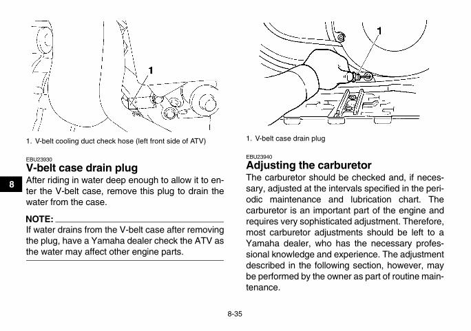
8-35
8
EBU23930
V-belt case drain plug After riding in water deep enough to allow it to en-ter the V-belt case, remove this plug to drain thewater from the case.
NOTE:If water drains from the V-belt case after removingthe plug, have a Yamaha dealer check the ATV asthe water may affect other engine parts.
EBU23940
Adjusting the carburetor The carburetor should be checked and, if neces-sary, adjusted at the intervals specified in the peri-odic maintenance and lubrication chart. Thecarburetor is an important part of the engine andrequires very sophisticated adjustment. Therefore,most carburetor adjustments should be left to aYamaha dealer, who has the necessary profes-sional knowledge and experience. The adjustmentdescribed in the following section, however, maybe performed by the owner as part of routine main-tenance.
1. V-belt cooling duct check hose (left front side of ATV) 1. V-belt case drain plug
U17S10E0.book Page 35 Friday, July 6, 2007 1:37 PM

8-36
8
CAUTION:ECB00480
The carburetor has been set and extensivelytested at the Yamaha factory. Changing thesesettings without sufficient technical knowl-edge may result in poor performance of ordamage to the engine.
EBU24010
Adjusting the engine idling speed The engine idling speed must be checked and, ifnecessary, adjusted as follows at the intervalsspecified in the periodic maintenance and lubrica-tion chart.
NOTE:A diagnostic tachometer is needed to make thisadjustment.
1. Start the engine and warm it up.
NOTE:The engine is warm when it quickly responds to thethrottle.
2. Remove panel D. (See page 8-9.)3. Attach the tachometer to the spark plug lead.
4. Check the engine idling speed and, if neces-sary, adjust it to specification by turning thethrottle stop screw at the carburetor. To in-crease the engine idling speed, turn the throt-tle stop screw in direction (a), and to decreaseit, turn the screw in direction (b).
NOTE:If the specified idling speed cannot be obtained asdescribed above, have a Yamaha dealer make theadjustment.
1. Throttle stop screw
Engine idling speed:1450–1550 r/min
U17S10E0.book Page 36 Friday, July 6, 2007 1:37 PM
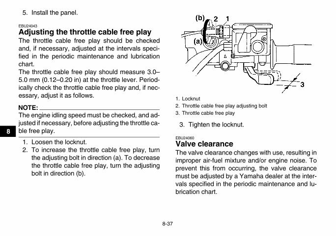
8-37
8
5. Install the panel.
EBU24043
Adjusting the throttle cable free play The throttle cable free play should be checkedand, if necessary, adjusted at the intervals speci-fied in the periodic maintenance and lubricationchart.The throttle cable free play should measure 3.0–5.0 mm (0.12–0.20 in) at the throttle lever. Period-ically check the throttle cable free play and, if nec-essary, adjust it as follows.
NOTE:The engine idling speed must be checked, and ad-justed if necessary, before adjusting the throttle ca-ble free play.
1. Loosen the locknut.2. To increase the throttle cable free play, turn
the adjusting bolt in direction (a). To decreasethe throttle cable free play, turn the adjustingbolt in direction (b).
3. Tighten the locknut.
EBU24060
Valve clearance The valve clearance changes with use, resulting inimproper air-fuel mixture and/or engine noise. Toprevent this from occurring, the valve clearancemust be adjusted by a Yamaha dealer at the inter-vals specified in the periodic maintenance and lu-brication chart.
1. Locknut2. Throttle cable free play adjusting bolt3. Throttle cable free play
U17S10E0.book Page 37 Friday, July 6, 2007 1:37 PM

8-38
8
EBU24070
Adjusting the drive select lever safety system cable The drive select lever safety system cable stretch-es with use, which can result in improper function.Therefore, the safety system cable should bechecked and adjusted at the intervals specified inthe periodic maintenance and lubrication chart.
EBU28413
Checking the front brake pads and rear brake friction plates The front brake pads and the rear brake frictionplates must be checked for wear at the intervalsspecified in the periodic maintenance and lubrica-tion chart.
NOTE:This ATV is equipped with a wet, multiple-disc typerear brake, which is located inside of the final gearcase.
EBU24171
Front brake padsCheck each front brake pad for damage and mea-sure the lining thickness. If a brake pad is dam-aged or if the lining thickness is less than 1.0 mm(0.04 in), have a Yamaha dealer replace the brakepads as a set.
NOTE:The wheels need to be removed to check thebrake pads. (See page 8-58.)
1. Lining thickness
U17S10E0.book Page 38 Friday, July 6, 2007 1:37 PM

8-39
8
EBU28421
Rear brake friction platesThe rear brake is provided with a wear indicator,which allows you to check the brake friction platewear without having to disassemble the brake. Tocheck the brake friction plate wear, check the posi-tion of the wear indicator while applying the brake.If a brake friction plate has worn to the point thatthe wear indicator reaches the wear limit mark,have a Yamaha dealer replace the brake frictionplates as a set.
EBU24251
Checking the brake fluid level Insufficient brake fluid may allow air to enter thebrake system, possibly causing it to become inef-fective.Before riding, check that the brake fluid is abovethe minimum level mark and replenish if neces-sary. A low brake fluid level may indicate wornbrake pads and/or brake system leakage. If thebrake fluid level is low, be sure to check the brakepads for wear and the brake system for leakage.
Observe these precautions:� When checking the fluid level, make sure that
the top of the brake fluid reservoir is level.
1. Wear indicator2. Wear limit mark
1. Minimum level mark
U17S10E0.book Page 39 Friday, July 6, 2007 1:37 PM
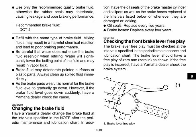
8-40
8
� Use only the recommended quality brake fluid,otherwise the rubber seals may deteriorate,causing leakage and poor braking performance.
� Refill with the same type of brake fluid. Mixingfluids may result in a harmful chemical reactionand lead to poor braking performance.
� Be careful that water does not enter the brakefluid reservoir when refilling. Water will signifi-cantly lower the boiling point of the fluid and mayresult in vapor lock.
� Brake fluid may deteriorate painted surfaces orplastic parts. Always clean up spilled fluid imme-diately.
� As the brake pads wear, it is normal for the brakefluid level to gradually go down. However, if thebrake fluid level goes down suddenly, have aYamaha dealer check the cause.
EBU24280
Changing the brake fluid Have a Yamaha dealer change the brake fluid atthe intervals specified in the NOTE after the peri-odic maintenance and lubrication chart. In addi-
tion, have the oil seals of the brake master cylinderand calipers as well as the brake hoses replaced atthe intervals listed below or whenever they aredamaged or leaking.� Oil seals: Replace every two years.� Brake hoses: Replace every four years.
EBU24380
Checking the front brake lever free play The brake lever free play must be checked at theintervals specified in the periodic maintenance andlubrication chart. The brake lever should have afree play of zero mm (zero in) as shown. If the freeplay is incorrect, have a Yamaha dealer check thebrake system.
Recommended brake fluid:DOT 4
1. Brake lever free play
U17S10E0.book Page 40 Friday, July 6, 2007 1:37 PM

8-41
8
WARNINGEWB02010 EBU28624
Adjusting the brake pedal and rear brake lever free play and checking the brake pedal position The brake pedal and brake lever free play and thebrake pedal position must be checked and, if nec-essary, adjusted at the intervals specified in theperiodic maintenance and lubrication chart.
NOTE:� Always perform this maintenance completely in
the following order whenever adjusting the rearbrake.
� When adjusting the rear brake, be sure to adjustboth the brake pedal and the brake lever.
� Before adjusting the brake lever and brake pedalfree play, check the rear brake friction plates forwear.
Adjusting the brake pedal and brake lever freeplayThe brake pedal free play should measure 17.0–20.0 mm (0.67–0.79 in). The brake lever free playshould measure 8.0–10.5 mm (0.31–0.41 in). If ei-ther free play is incorrect, adjust it as follows.
POTENTIAL HAZARDOperating with improperly serviced or ad-justed brakes.WHAT CAN HAPPENYou could lose braking ability, which couldlead to an accident.HOW TO AVOID THE HAZARDAfter servicing:� Make sure the brakes operate smoothly
and that the free play is correct.� Make sure the brakes do not drag.� Make sure the brakes are not spongy. All
air must be bled from the brake system.Replacement of brake components requiresprofessional knowledge. These proceduresshould be performed by a Yamaha dealer.
U17S10E0.book Page 41 Friday, July 6, 2007 1:37 PM

8-42
8
1. Loosen the locknut at the brake lever and fullyturn in the brake lever free play adjusting bolt.
2. Fully loosen the brake lever free play adjust-ing nut on the brake cable at the final gearcase.
1. Brake pedal free play
1. Brake lever free play
1. Locknut2. Brake lever free play adjusting bolt
U17S10E0.book Page 42 Friday, July 6, 2007 1:37 PM

8-43
8
3. Push the brake camshaft lever in direction (a)until it stops [apply approximately 50 N (5.0kgf, 11.0 lbf) of force], and then turn the brakepedal free play adjusting nut on the brake ca-ble at the final gear case so that gap “A” mea-sures 2.5–3.0 mm (0.10–0.12 in).
4. Push the brake camshaft lever in direction (a)until it stops [apply approximately 50 N (5.0kgf, 11.0 lbf) of force], and then turn the brakelever free play adjusting nut on the brake ca-ble at the final gear case so that gap “B” mea-sures 4.0–6.0 mm (0.16–0.24 in).
1. Brake lever free play adjusting nut 1. Brake pedal free play adjusting nut2. Brake camshaft lever3. Gap “A”
U17S10E0.book Page 43 Friday, July 6, 2007 1:37 PM

8-44
85. Check the brake lever free play and, if neces-
sary, adjust it by turning the brake lever freeplay adjusting bolt at the brake lever. Turn thebrake lever free play adjusting bolt in direction(a) to increase the free play, and in direction(b) to decrease it.
6. Tighten the locknut at the brake lever.
NOTE:When adjusting the rear brake lever free play:� Be sure not to step on the brake pedal.� Make sure the brake pedal does not move.
Checking the brake pedal positionThe top of the brake pedal should be positioned75.0–85.0 mm (2.95–3.35 in) above the footboard.If the brake pedal position is incorrect, have aYamaha dealer adjust it.
1. Brake lever free play adjusting nut2. Brake camshaft lever3. Gap “B”
1. Locknut2. Brake lever free play adjusting bolt
U17S10E0.book Page 44 Friday, July 6, 2007 1:37 PM

8-45
8
WARNINGEWB02020
EBU24230
Axle boots The axle boots must be checked for damage at theintervals specified in the periodic maintenance andlubrication chart. Check the axle boots for tears ordamage. If any damage is found, have them re-placed by a Yamaha dealer.
1. Distance between brake pedal and footboard
POTENTIAL HAZARDOperating with improperly serviced or ad-justed brakes.WHAT CAN HAPPENYou could lose braking ability, which couldlead to an accident.
HOW TO AVOID THE HAZARDAfter servicing:� Make sure the brakes operate smoothly
and that the free play is correct.� Make sure the brakes do not drag.Replacement of brake components requiresprofessional knowledge. These proceduresshould be performed by a Yamaha dealer.
U17S10E0.book Page 45 Friday, July 6, 2007 1:37 PM

8-46
8
EBU24751
Brake light switches The operation of the brake light switches must bechecked and, if necessary, adjusted at the inter-vals specified in the periodic maintenance and lu-brication chart.The brake light switch for the brake pedal can beadjusted as follows, but the other brake lightswitches should be adjusted by a Yamaha dealer.
1. Remove panel B. (See page 8-9.)
NOTE:The brake light switch is properly adjusted whenthe brake light comes on just before braking takeseffect.
2. Turn the adjusting nut while holding the brakelight switch in place. To make the brake lightcome on earlier, turn the adjusting nut in direc-tion (a). To make the brake light come on lat-er, turn the adjusting nut in direction (b).
1. Front axle boot (each side)
1. Rear axle boot (each side)
U17S10E0.book Page 46 Friday, July 6, 2007 1:37 PM

8-47
8
3. Install the panel.
EBU24890
Checking and lubricating the cables The operation and the condition of all control ca-bles should be checked before each ride, and thecables and cable ends should be lubricated if nec-essary. If a cable is damaged or does not movesmoothly, have a Yamaha dealer check or replaceit.
WARNINGEWB02120
EBU28711
Checking and lubricating the front and rear brake levers The operation of the front and rear brake leversshould be checked before each ride, and the leverpivots should be lubricated if necessary.
1. Brake light switch2. Brake light switch adjusting nut
Recommended lubricant:Engine oil
POTENTIAL HAZARDDamaged control cables.WHAT CAN HAPPENCorrosion can result when the cable sheathsbecome damaged, and cables can also be-come frayed or kinked, which could restrictthe operation of controls and lead to an acci-dent or injury.HOW TO AVOID THE HAZARDInspect cables frequently. Replace damagedcables.
Recommended lubricants:Front brake lever:
Silicone greaseRear brake lever:
Lithium-soap-based grease
U17S10E0.book Page 47 Friday, July 6, 2007 1:37 PM

8-48
8
EBU28832
Checking and lubricating the brake pedal The operation of the brake pedal should bechecked before each ride, and the pedal pivotshould be lubricated if necessary.
NOTE:To access the brake pedal pivot, remove panel B.(See page 8-9.)
EBU24962
Checking the wheel hub bearings The front and rear wheel hub bearings must bechecked at the intervals specified in the periodicmaintenance and lubrication chart. If there is playin a wheel hub or if a wheel does not turn smoothly,have a Yamaha dealer check the wheel hub bear-ings.
EBU24970
Lubricating the drive shaft universal joint The drive shaft universal joint must be lubricated atthe intervals specified in the periodic maintenanceand lubrication chart.
Recommended lubricant:Lithium-soap-based grease
U17S10E0.book Page 48 Friday, July 6, 2007 1:37 PM

8-49
8
Lubricate the universal joint using a grease gun.
EBU25021
Checking the stabilizer bushes The stabilizer bushes must be checked for cracksor damage at the intervals specified in the periodicmaintenance and lubrication chart.Have a Yamaha dealer replace the stabilizer bush-es if necessary.
EBU25051
Lubricating the rear knuckle pivots The rear knuckle pivots must be lubricated at theintervals specified in the periodic maintenance andlubrication chart.Lubricate the pivoting points using a grease gun.
EBU25102
Lubricating the steering shaft The steering shaft must be lubricated at the inter-vals specified in the periodic maintenance and lu-brication chart.
Recommended lubricant:Lithium-soap-based grease
Recommended lubricant:Lithium-soap-based grease
1. Grease nipple
Recommended lubricant:Lithium-soap-based grease
U17S10E0.book Page 49 Friday, July 6, 2007 1:37 PM
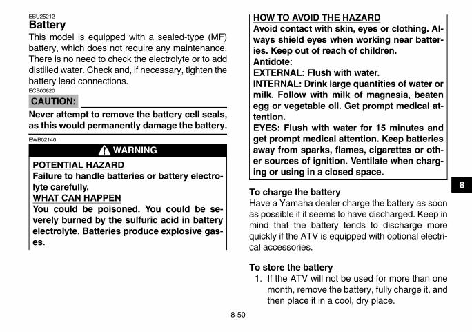
8-50
8
EBU25212
Battery This model is equipped with a sealed-type (MF)battery, which does not require any maintenance.There is no need to check the electrolyte or to adddistilled water. Check and, if necessary, tighten thebattery lead connections.
CAUTION:ECB00620
Never attempt to remove the battery cell seals,as this would permanently damage the battery.
WARNINGEWB02140
To charge the batteryHave a Yamaha dealer charge the battery as soonas possible if it seems to have discharged. Keep inmind that the battery tends to discharge morequickly if the ATV is equipped with optional electri-cal accessories.
To store the battery1. If the ATV will not be used for more than one
month, remove the battery, fully charge it, andthen place it in a cool, dry place.
POTENTIAL HAZARDFailure to handle batteries or battery electro-lyte carefully.WHAT CAN HAPPENYou could be poisoned. You could be se-verely burned by the sulfuric acid in batteryelectrolyte. Batteries produce explosive gas-es.
HOW TO AVOID THE HAZARDAvoid contact with skin, eyes or clothing. Al-ways shield eyes when working near batter-ies. Keep out of reach of children.Antidote:EXTERNAL: Flush with water.INTERNAL: Drink large quantities of water ormilk. Follow with milk of magnesia, beatenegg or vegetable oil. Get prompt medical at-tention.EYES: Flush with water for 15 minutes andget prompt medical attention. Keep batteriesaway from sparks, flames, cigarettes or oth-er sources of ignition. Ventilate when charg-ing or using in a closed space.
U17S10E0.book Page 50 Friday, July 6, 2007 1:37 PM

8-51
8
2. If the battery will be stored for more than twomonths, check it at least once a month and ful-ly charge it if necessary.
To install the battery
NOTE:Be sure the battery is fully charged.
1. Place the battery in its compartment.2. Make sure to properly connect the battery
leads to the battery terminals.
CAUTION:ECB00630
� Always keep the battery charged. Storing adischarged battery can cause permanentbattery damage.
� To charge a sealed-type (MF) battery, a spe-cial constant-voltage battery charger is re-quired. Using a conventional battery chargerwill damage the battery. If you do not haveaccess to a constant-voltage battery charg-er, have a Yamaha dealer charge your bat-tery.
1. Positive battery lead (red)2. Negative battery lead (black)
U17S10E0.book Page 51 Friday, July 6, 2007 1:37 PM

8-52
8
EBU25313
Replacing a fuse
1. Main fuse2. Fuse box
1. Main fuse2. Spare main fuse
U17S10E0.book Page 52 Friday, July 6, 2007 1:37 PM

8-53
8
The main fuse and the fuse box are located underthe seat. (See page 4-19.)If a fuse is blown, replace it as follows.
1. Turn the key to “OFF” and turn off all electricalcircuits.
CAUTION:ECB00640
To prevent accidental short-circuiting, turn offthe main switch when checking or replacing afuse.
2. Remove the blown fuse, and then install anew fuse of the specified amperage.
1. Headlight fuse2. Ignition fuse3. Auxiliary DC jack fuse4. Four-wheel-drive motor fuse5. Signaling system fuse6. Backup fuse (for odometer and clock)7. Spare fuse
Specified fuses:Main fuse:
30.0 AHeadlight fuse:
15.0 AIgnition fuse:
10.0 AFour-wheel-drive motor fuse:
10.0 ASignaling system fuse:
10.0 AAuxiliary DC jack fuse:
10.0 ABackup fuse:
10.0 A
U17S10E0.book Page 53 Friday, July 6, 2007 1:37 PM

8-54
8
WARNINGEWB02151
3. Turn the key to “ON” and turn on the electricalcircuits to check if the devices operate.
4. If the fuse immediately blows again, have aYamaha dealer check the electrical system.
EBU25470
Replacing a headlight bulb If a headlight bulb burns out, replace it as follows.
1. Remove the cover at the rear of the headlightby pulling it off.
2. Remove the headlight bulb holder cover bypulling it off.
POTENTIAL HAZARDUsing an improper fuse.WHAT CAN HAPPENAn improper fuse can cause damage to theelectrical system, which could lead to a fire.HOW TO AVOID THE HAZARDAlways use a fuse of the specified rating.Never use a material in place of the properfuse.
1. Cover at the rear of the headlight
1. Headlight bulb holder cover
U17S10E0.book Page 54 Friday, July 6, 2007 1:37 PM

8-55
8
3. Remove the headlight bulb holder by pushingit in and turning it counterclockwise.
4. Remove the defective bulb by pulling it out.
WARNINGEWB02180
5. Insert a new headlight bulb into the bulb hold-er by pushing it in.
CAUTION:ECB00650
Do not touch the glass part of the headlightbulb to keep it free from oil, otherwise thetransparency of the glass, the luminosity of thebulb, and the bulb life will be adversely affect-ed. Thoroughly clean off any dirt and finger-prints on the headlight bulb using a clothmoistened with alcohol or thinner.
6. Install the bulb holder by pushing it in and turn-ing it clockwise.
1. Headlight bulb holder
POTENTIAL HAZARDA headlight bulb is hot when it is on and im-mediately after it is turned off.WHAT CAN HAPPENYou can be burned, or a fire could start if thebulb touches something flammable.HOW TO AVOID THE HAZARDWait for the bulb to cool before touching orremoving it.
1. Do not touch the glass part of the bulb.
U17S10E0.book Page 55 Friday, July 6, 2007 1:37 PM

8-56
8
7. Install the bulb holder cover and the cover atthe rear of the headlight.
CAUTION:ECB00670
Make sure the headlight bulb holder cover issecurely fitted over the bulb holder and seatedproperly.
8. Adjust the headlight beam if necessary.
EBU25550
Adjusting a headlight beam
CAUTION:ECB00690
It is advisable to have a Yamaha dealer makethis adjustment.
To raise a headlight beam, turn the adjustingscrew in direction (a).To lower a headlight beam, turn the adjustingscrew in direction (b).
EBU25620
Replacing the tail/brake light bulb If the tail/brake light bulb burns out, replace it asfollows.
1. Remove the tail/brake light assembly by re-moving the nuts together with the washers.
1. Headlight beam adjusting screw
U17S10E0.book Page 56 Friday, July 6, 2007 1:37 PM

8-57
8
2. Remove the bulb holder (together with thebulb) by turning it counterclockwise.
3. Remove the defective bulb by pushing it inand turning it counterclockwise.
1. Tail/brake light assembly2. Nut
1. Tail/brake light assembly2. Tail/brake light bulb holder
U17S10E0.book Page 57 Friday, July 6, 2007 1:37 PM

8-58
8
4. Insert a new bulb into the bulb holder, push itin, and then turn it clockwise until it stops.
5. Install the bulb holder (together with the bulb)by turning it clockwise.
6. Install the tail/brake light assembly by install-ing the washers and the nuts.
EBU25650
Removing a wheel 1. Loosen the wheel nuts.
2. Elevate the ATV and place a suitable standunder the frame.
3. Remove the nuts from the wheel.4. Remove the wheel.
EBU25700
Installing a wheel 1. Install the wheel and the nuts.
NOTE:� The arrow mark on the tire must point toward
the rotating direction of the wheel.
1. Tail/brake light bulb holder2. Tail/brake light bulb
1. Wheel nut
U17S10E0.book Page 58 Friday, July 6, 2007 1:37 PM

8-59
8
� Tapered nuts are used for both the front and rearwheels. Install the nuts with their tapered side to-wards the wheel.
2. Lower the ATV to the ground.3. Tighten the wheel nuts to the specified
torques.1. Arrow mark
1. Tapered nut
Tightening torques:Front wheel nut:
55 Nm (5.5 m·kgf, 40 ft·lbf)Rear wheel nut:
55 Nm (5.5 m·kgf, 40 ft·lbf)
U17S10E0.book Page 59 Friday, July 6, 2007 1:37 PM
8-60
8
EBU25730
Troubleshooting Although Yamaha ATVs receive a thorough in-spection before shipment from the factory, troublemay occur during operation. Any problem in the fu-el, compression, or ignition systems, for example,can cause poor starting and loss of power.The following troubleshooting charts representquick and easy procedures for checking these vitalsystems yourself. However, should your ATV re-quire any repair, take it to a Yamaha dealer, whoseskilled technicians have the necessary tools, expe-rience, and know-how to service the ATV properly.Use only genuine Yamaha replacement parts. Im-itation parts may look like Yamaha parts, but theyare often inferior, have a shorter service life andcan lead to expensive repair bills.
WARNINGEWB02260
POTENTIAL HAZARDChecking the fuel system while smoking ornear an open flame.WHAT CAN HAPPENFuel can ignite or explode, causing severeinjury or property damage.
HOW TO AVOID THE HAZARDDo not smoke when checking the fuel sys-tem. Make sure there are no open flames orsparks in the area, including pilot lights fromwater heaters or furnaces.
U17S10E0.book Page 60 Friday, July 6, 2007 1:37 PM

8-61
8
EBU25771
Troubleshooting charts
Starting problems or poor engine performance
Check the fuel level inthe fuel tank.
1. FuelThere is enough fuel.
There is no fuel.
Check the compression.
Supply fuel. The engine does not start. Check the compression.
Operate the electric starter.
2. CompressionThere is compression.
There is no compression.
Check the ignition.
Have a Yamaha dealercheck the ATV.
Remove the spark plugand check the electrodes.
3. Ignition Wipe off with a dry cloth and correct thespark plug gap, or replace the spark plug.
Have a Yamaha dealer check the ATV.
The engine does not start.Have a Yamaha dealercheck the ATV.
The engine does not start.Check the battery.
Operate the electric starter.
4. BatteryThe engine turns over quickly.
The engine turns over slowly.
The battery is good.
Check the battery lead connections,and charge the battery if necessary.
Dry
WetOpen the throttle halfway and operatethe electric starter.
U17S10E0.book Page 61 Friday, July 6, 2007 1:37 PM

8-62
8
Engine overheating
WARNINGEWB02270
NOTE:If coolant is not available, tap water can be temporarily used instead, provided that it is changed to the rec-ommended coolant as soon as possible.
POTENTIAL HAZARDRemoving the radiator cap when the engine and radiator are still hot.WHAT CAN HAPPENYou could be burned by hot fluid and steam blown out under pressure.HOW TO AVOID THE HAZARDWait for the engine to cool before removing the radiator cap. Always use a thick rag over the cap.Allow any remaining pressure to escape before completely removing the cap.
Wait until the engine has cooled.
Check the coolant level in the reservoir and radiator.
The coolant level is OK.
The coolant level is low.Check the cooling systemfor leakage.
Have a Yamaha dealer checkand repair the cooling system.
Add coolant. (See NOTE.)
Start the engine. If the engine overheats again, have a Yamaha dealer check and repair the cooling system.
There isleakage.
There is no leakage.
U17S10E0.book Page 62 Friday, July 6, 2007 1:37 PM

9-1
9
EBU25860
CLEANING AND STORAGEEBU25870
Cleaning Frequent, thorough cleaning of your ATV will notonly enhance its appearance but will improve itsgeneral performance and extend the useful life ofmany components.
1. Before cleaning the ATV:a. Block off the end of the exhaust pipe to
prevent water entry. A plastic bag andstrong rubber band may be used.
b. Make sure the spark plug and all filler capsare properly installed.
2. If the engine case is excessively greasy, applydegreaser with a paint brush. Do not apply de-greaser to the wheel axles.
3. Rinse the dirt and degreaser off with a gardenhose. Use only enough pressure to do the job.
CAUTION:ECB00710
Excessive water pressure may cause waterseepage and deterioration of wheel bearings,brakes, transmission seals and electrical de-vices. Many expensive repair bills have result-
ed from improper high-pressure detergentapplications such as those available in coin-operated car washers.
4. Once most of the dirt has been hosed off,wash all surfaces with warm water and mild,detergent-type soap. An old toothbrush or bot-tle brush is handy for hard-to-reach places.
5. Rinse the ATV off immediately with clean wa-ter and dry all surfaces with a chamois, cleantowel or soft absorbing cloth.
6. Clean the seat with a vinyl upholstery cleanerto keep the cover pliable and glossy.
7. Automotive type wax may be applied to allpainted and chrome plated surfaces. Avoidcombination cleaner-waxes. Many containabrasives which may mar the paint or protec-tive finish. When finished cleaning, start theengine and let it idle for several minutes.
WARNINGEWB02300
POTENTIAL HAZARDOperation with wet brakes after washing.
U17S10E0.book Page 1 Friday, July 6, 2007 1:37 PM

9-2
9
EBU25932
Storage
Short-termAlways store your ATV in a cool, dry place and, ifnecessary, protect it against dust with a porouscover.
CAUTION:ECB00720
� Storing the ATV in a poorly ventilated roomor covering it with a tarp while it is still wet,will allow water and humidity to seep in andcause rust.
� To prevent corrosion, avoid damp cellars,stables (because of the presence of ammo-nia) and areas where strong chemicals arestored.
Long-termBefore storing your ATV for several months:
1. Follow all the instructions in the “Cleaning”section of this chapter.
2. Turn the fuel cock lever to “OFF”.3. Drain the carburetor float chamber by loosen-
ing the drain bolt; this will prevent fuel depositsfrom building up. Pour the drained fuel into thefuel tank.
4. Fill up the fuel tank and add fuel stabilizer (ifavailable) to prevent the fuel from deteriorat-ing.
5. Perform the following steps to protect the cyl-inder, piston rings, etc. from corrosion.a. Remove the spark plug cap and spark
plug.b. Pour a teaspoonful of engine oil into the
spark plug bore.
WHAT CAN HAPPENWet brakes may have reduced stopping abil-ity, increasing the chance of an accident.HOW TO AVOID THE HAZARDTest the brakes after washing. Apply thebrakes several times at slow speeds to letfriction dry out the linings.
Specified amount:7.5 ml of stabilizer to each liter of fuel (or 1 oz of stabilizer to each gallon of fuel)
U17S10E0.book Page 2 Friday, July 6, 2007 1:37 PM

9-3
9
c. Install the spark plug cap onto the sparkplug, and then place the spark plug on thecylinder head so that the electrodes aregrounded. (This will limit sparking duringthe next step.)
d. Turn the engine over several times with thestarter. (This will coat the cylinder wall withoil.)
e. Remove the spark plug cap from the sparkplug, and then install the spark plug andthe spark plug cap.
6. Lubricate all control cables and the pivotingpoints of all levers and pedals.
7. Check and, if necessary, correct the tire airpressure, and then block up the ATV so thatall of its wheels are off the ground. Alternative-ly, turn the wheels a little every month in orderto prevent the tires from becoming degradedin one spot.
8. Cover the muffler outlet with a plastic bag toprevent moisture from entering it.
9. Remove the battery and fully charge it. Storeit in a cool, dry place and charge it once amonth. Do not store the battery in an exces-sively cold or warm place [less than 0 °C (30
°F) or more than 30 °C (90 °F)]. For more in-formation on storing the battery, see page8-50.
NOTE:Make any necessary repairs before storing theATV.
U17S10E0.book Page 3 Friday, July 6, 2007 1:37 PM

10-1
10
EBU25960
SPECIFICATIONS Dimensions:
Overall length:1993 mm (78.5 in)
Overall width:1093 mm (43.0 in)
Overall height:1120 mm (44.1 in)
Seat height:830 mm (32.7 in)
Wheelbase:1233 mm (48.5 in)
Ground clearance:245 mm (9.6 in)
Minimum turning radius:3000 mm (118 in)
Weight:With oil and fuel:
285.0 kg (628 lb)Engine:
Engine type:Liquid cooled 4-stroke, SOHC
Cylinder arrangement:Forward-inclined single cylinder
Displacement:421.0 cm³
Bore × stroke:84.5 × 75.0 mm (3.33 × 2.95 in)
Compression ratio:10.00 :1
Starting system:Electric and recoil starter
Lubrication system:Wet sump
Engine oil:Type:
YAMALUBE 4, SAE5W30 or SAE10W30 or SAE20W40
Recommended engine oil grade:API service SG type or higher, JASO standard MA
Engine oil quantity:Without oil filter cartridge replacement:
2.30 L (2.43 US qt) (2.02 Imp.qt)
0˚ 10˚ 30˚ 50˚ 70˚ 90˚ 110˚ 130˚F
YAMALUBE 4 (10W30) or SAE 10W30
YAMALUBE 4-CW (5W30) or SAE 5W30
-20˚ -10˚ 0˚ 10˚ 20˚ 30˚ 40˚ 50˚C
YAMALUBE 4 (20W40) or SAE 20W40
U17S10E0.book Page 1 Friday, July 6, 2007 1:37 PM

10-2
10
With oil filter cartridge replacement:2.40 L (2.54 US qt) (2.11 Imp.qt)
Final gear oil:Type:
Yamaha Friction Modified Shaft Drive Gear Oil (Part No.: ACC-SHAFT-LU-00)
Quantity:0.50 L (0.53 US qt) (0.44 Imp.qt)
Differential gear oil:Type:
Yamaha Friction Modified Shaft Drive Gear Oil (Part No.: ACC-SHAFT-LU-00) or SAE80 API GL-4 Hypoid gear oil
Quantity:0.23 L (0.24 US qt) (0.20 Imp.qt)
Cooling system:Coolant reservoir capacity (up to the maximum level mark):
0.25 L (0.26 US qt) (0.22 Imp.qt)Radiator capacity (including all routes):
1.30 L (1.37 US qt) (1.14 Imp.qt)Air filter:
Air filter element:Wet element
Fuel:Recommended fuel:
Unleaded gasoline onlyFuel tank capacity:
15.0 L (3.96 US gal) (3.30 Imp.gal)Fuel reserve amount:
4.5 L (1.19 US gal) (0.99 Imp.gal)
Carburetor:Manufacturer:
MIKUNIType x quantity:
BSR33 x 1Spark plug (s):
Manufacturer/model:NGK/DR8EA
Spark plug gap:0.6–0.7 mm (0.024–0.028 in)
Clutch:Clutch type:
Wet, centrifugal automaticTransmission:
Primary reduction system:V-belt
Secondary reduction system:Shaft drive
Secondary reduction ratio:39/24 × 24/18 × 33/9 (7.944)
Transmission type:V-belt automatic
Operation:Left hand operation
Reverse gear:29/17 (1.706)
Low range:45/16 (2.813)
High range:38/23 (1.652)
U17S10E0.book Page 2 Friday, July 6, 2007 1:37 PM
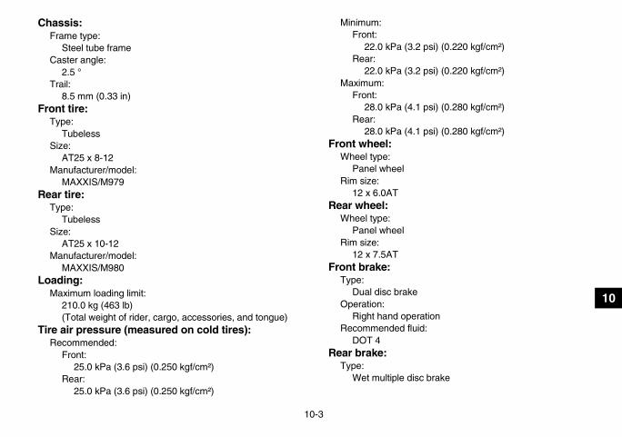
10-3
10
Chassis:Frame type:
Steel tube frameCaster angle:
2.5 °Trail:
8.5 mm (0.33 in)Front tire:
Type:Tubeless
Size:AT25 x 8-12
Manufacturer/model:MAXXIS/M979
Rear tire:Type:
TubelessSize:
AT25 x 10-12Manufacturer/model:
MAXXIS/M980Loading:
Maximum loading limit:210.0 kg (463 lb)(Total weight of rider, cargo, accessories, and tongue)
Tire air pressure (measured on cold tires):Recommended:
Front:25.0 kPa (3.6 psi) (0.250 kgf/cm²)
Rear:25.0 kPa (3.6 psi) (0.250 kgf/cm²)
Minimum:Front:
22.0 kPa (3.2 psi) (0.220 kgf/cm²)Rear:
22.0 kPa (3.2 psi) (0.220 kgf/cm²)Maximum:
Front:28.0 kPa (4.1 psi) (0.280 kgf/cm²)
Rear:28.0 kPa (4.1 psi) (0.280 kgf/cm²)
Front wheel:Wheel type:
Panel wheelRim size:
12 x 6.0ATRear wheel:
Wheel type:Panel wheel
Rim size:12 x 7.5AT
Front brake:Type:
Dual disc brakeOperation:
Right hand operationRecommended fluid:
DOT 4Rear brake:
Type:Wet multiple disc brake
U17S10E0.book Page 3 Friday, July 6, 2007 1:37 PM

10-4
10
Operation:Left hand and right foot operation
Front suspension:Type:
Double wishboneSpring/shock absorber type:
Coil spring/oil damperWheel travel:
160 mm (6.3 in)Rear suspension:
Type:Double wishbone
Spring/shock absorber type:Coil spring/oil damper
Wheel travel:180 mm (7.1 in)
Electrical system:Ignition system:
DC. CDICharging system:
AC magnetoBattery:
Model:YTX20L-BS
Voltage, capacity:12 V, 18.0 Ah
Headlight:Bulb type:
Krypton bulb
Bulb voltage, wattage x quantity:Headlight:
12 V, 30.0/30.0 W × 2Tail/brake light:
12 V, 5.0/21.0 W × 1Neutral indicator light:
LEDReverse indicator light:
LEDCoolant temperature warning light:
LEDPark indicator light:
LEDOn-Command four-wheel-drive/differential gear lock indicator:
LCDHigh-range indicator light:
LEDLow-range indicator light:
LEDDifferential gear lock indicator light:
LEDFuses:
Main fuse:30.0 A
Headlight fuse:15.0 A
Signaling system fuse:10.0 A
Ignition fuse:10.0 A
U17S10E0.book Page 4 Friday, July 6, 2007 1:37 PM
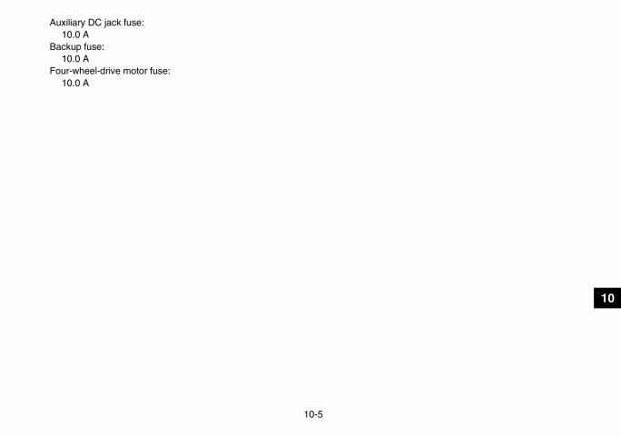
10-5
10
Auxiliary DC jack fuse:10.0 A
Backup fuse:10.0 A
Four-wheel-drive motor fuse:10.0 A
U17S10E0.book Page 5 Friday, July 6, 2007 1:37 PM

11-1
11
EBU25981
CONSUMER INFORMATIONEBU26011
Identification numbers Record the key identification number, vehicle iden-tification number and model label information inthe spaces provided below for assistance when or-dering spare parts from a Yamaha dealer or for ref-erence in case the ATV is stolen.KEY IDENTIFICATION NUMBER:
VEHICLE IDENTIFICATION NUMBER:
MODEL LABEL INFORMATION:
EBU26020
Key identification number The key identification number is stamped into thekey. Record this number in the space provided anduse it for reference when ordering a new key.
EBU26030
Vehicle identification number The vehicle identification number is stamped intothe frame.
1. Key identification number
U17S10E0.book Page 1 Friday, July 6, 2007 1:37 PM

11-2
11
NOTE:The vehicle identification number is used to identifyyour ATV.
EBU26050
Model label The model label is affixed at the location in the il-lustration. Record the information on this label inthe space provided. This information will be need-ed when ordering spare parts from a Yamaha deal-er.
1. Vehicle identification number (front left side) 1. Model label
U17S10E0.book Page 2 Friday, July 6, 2007 1:37 PM

11-3
11
EBU26060
Noise regulation TAMPERING WITH NOISE CONTROL SYSTEM PROHIBITED:Federal law prohibits the following acts or the causing thereof: (1) The removal or rendering inoperative byany person other than for purposes of maintenance, repair, or replacement of any device or element of de-sign incorporated into any new vehicle for the purpose of noise control prior to its sale or delivery to the ul-timate purchaser or while it is in use or (2) the use of the vehicle after such device or element of design hasbeen removed or rendered inoperative by any person.“AMONG THOSE ACTS PRESUMED TO CONSTITUTE TAMPERING ARE THE ACTS LISTED BELOW”.These acts include tampering with the following systems; i.e., modification, removal, etc.
Exhaust system• Muffler• Exhaust pipe• Silencer
Intake system• Air cleaner case• Air cleaner element• Intake duct
U17S10E0.book Page 3 Friday, July 6, 2007 1:37 PM

11-4
11
EBU26080
Maintenance record Copies of work orders and/or receipts for parts you purchase and install will be required to document main-tenance done in accordance with the warranty. The chart below is printed only as a reminder to you that themaintenance work is required. It is not acceptable proof of maintenance work.
MAINTENANCE INTERVAL DATE OF SERVICE MILEAGE SERVICING DEALER
NAME AND ADDRESS REMARKSmonth km (mi) hours
1 320 (200) 203 1300 (800) 806 2500 (1600) 16012 5000 (3200) 32018 7500 (4800) 48024 10000 (6400) 64030 12500 (8000) 80036 15000 (9600) 96042 17500 (11200) 112048 20000 (12800) 128054 22500 (14400) 144060 25000 (16000) 1600
U17S10E0.book Page 4 Friday, July 6, 2007 1:37 PM

11-5
11
EBU26501
YAMAHA MOTOR CORPORATION, U.S.A. ATV LIMITED WARRANTY
Yamaha Motor Corporation, U.S.A. hereby warrants that new Yamaha ATVs purchased from an authorized Yamaha ATV dealer in the continental United States will be free from defects in material and workmanship for the period of time stated herein, sub-ject to certain stated limitations.
THE PERIOD OF WARRANTY for Yamaha ATVs shall be six (6) months from the date of purchase.
DURING THE PERIOD OF WARRANTY any authorized Yamaha ATV dealer will, free of charge, repair or replace any part adjudged defective by Yamaha due to faulty workmanship or material from the factory. Parts used in warranty repairs will be warranted for the balance of the product’s warranty period. All parts replaced under warranty become property of Yamaha Motor Corp. U.S.A.
GENERAL EXCLUSIONS from this warranty shall include any failures caused by:a. Competition or racing use.b. Installation of parts or accessories that are not
qualitatively equivalent to genuine Yamaha parts.c. Abnormal strain, neglect, or abuse.d. Lack of proper maintenance.e. Accident or collision damage. f. Modification to original parts.g. Damage due to improper transportation.
SPECIFIC EXCLUSIONS from this warranty shall include parts replaced due to normal wear or routine maintenance, such as spark plugs, oil, oil filter, air filter, and brake shoes.
THE CUSTOMER’S RESPONSIBILITY under this war-ranty shall be to:1. Operate and maintain the ATV as specified in the
appropriate owner’s manual;2. Give notice to an authorized Yamaha ATV dealer
of any and all apparent defects within ten (10) days after discovery, and make the machine available at that time for inspection and repairs at such dealer’s place of business.
WARRANTY TRANSFER: To transfer the warranty from the original purchaser to any subsequent pur-chaser(s), it is imperative that the machine be inspected and registered for warranty by an autho-rized Yamaha ATV dealer. In order for this warranty to remain in effect, this inspection and registration must take place within ten (10) days after transfer. An inspection and registration fee will be charged for this service.
EMISSION CONTROL SYSTEM WARRANTYYamaha Motor Corporation, USA also warrants to the ultimate purchaser and each subsequent pur-chaser of each 2006 and later model Yamaha ATV covered by this warranty that the vehicle is designed, built, and equipped so as to conform at the time of sale with all U.S. emissions standards applicable at the time of manufacture and that it is free from defects in materials and workmanship which would cause it not to meet these standards
within the period listed immediately below. Failures other than those resulting from defects in material or workmanship which arise solely as a result of owner abuse and/or lack of proper maintenance are not covered by this warranty.
All ModelsThirty (30) months from the original purchase date
YAMAHA MOTOR CORPORATION, U.S.A. MAKES NO OTHER WARRANTY OF ANY KIND, EXPRESSED OR IMPLIED. ALL IMPLIED WARRANTIES OF MERCHANTABILITY AND FITNESS FOR A PARTICULAR PURPOSE WHICH EXCEED THE OBLIGATIONS AND TIME LIMITS STATED IN THIS WARRANTY ARE HEREBY DISCLAIMED BY YAMAHA MOTOR CORPORATION, U.S.A. AND EXCLUDED FROM THIS WARRANTY.
SOME STATES DO NOT ALLOW LIMITATIONS ON HOW LONG AN IMPLIED WARRANTY LASTS, SO THE ABOVE LIMITATION MAY NOT APPLY TO YOU. ALSO EXCLUDED FROM THIS WARRANTY ARE ANY INCIDENTAL OR CONSEQUENTIAL DAMAGES INCLUDING LOSS OF USE. SOME STATES DO NOT ALLOW THE EXCLUSION OR LIMITATION OF INCIDENTAL OR CONSEQUENTIAL DAMAGES, SO THE ABOVE EXCLUSION MAY NOT APPLY TO YOU.
THIS WARRANTY GIVES YOU SPECIFIC LEGAL RIGHTS, AND YOU MAY ALSO HAVE OTHER RIGHTS WHICH VARY FROM STATE TO STATE.
YAMAHA MOTOR CORPORATION, U.S.A.P.O. Box 6555
Cypress, California 90630
U17S10E0.book Page 5 Friday, July 6, 2007 1:37 PM

11-6
11
WARRANTY QUESTIONS AND ANSWERS
Q. What costs are my responsibility during the warranty period?A. The customer’s responsibility includes all costs of normal maintenance services,
non-warranty repairs, accident and collision damages, and oil, oil filters, air filters, spark plugs, and brake shoes.
Q. What are some examples of “abnormal” strain, neglect, or abuse?A. These terms are general and overlap each other in areas. Specific examples include:
Running the machine out of oil, sustained high rpm, full-throttle, operating the machine with a broken or damaged part which causes another part to fail, damage or failure due to improper or careless transportation and or tie-down. If you have any specific questions on operation or maintenance, please contact your dealer for advice.
Q. Does the warranty cover incidental costs such as towing or transportation due to a failure?
A. No. The warranty is limited to repair of the machine itself.
Q. May I perform any or all of the recommended maintenance shown in the Owner’s Manual instead of having the dealer do them?
A. Yes, if you are a qualified mechanic and follow the procedures specified in the Owner’s and Service Manual. We do recommend, however, that items requiring special tools or equipment be done by a Yamaha ATV dealer.
Q. Will the warranty be void or cancelled if I do not operate or maintain my new ATV exactly as specified in the Owner’s Manual?
A. No. The warranty on a new ATV cannot be “voided” or “cancelled.” However, if a particular failure is caused by operation or maintenance other than as described in the Owner’s Manual, that failure may not be covered under warranty.
Q. What responsibility does my dealer have under this warranty?A. Each Yamaha ATV dealer is expected to:
1. Completely set up every new machine before sale.2. Explain the operation, maintenance, and warranty requirements to your satis-
faction at the time of sale, and upon your request at any later date.3. Each Yamaha ATV dealer is held responsible for his setup, service and war-
ranty repair work.
Q. Is the warranty transferable to second owners?A. Yes. The remainder of the existing warranty can be transferred upon request. The
unit has to be inspected and re-registered by an authorized Yamaha ATV dealer for the policy to remain effective.
CUSTOMER SERVICE
If your machine requires warranty service, you must take it to any authorized Yamaha ATV dealer within the continental United States. Be sure to bring your warranty registration card or other valid proof of the original date of purchase. If a question or problem arises regarding warranty, first contact the owner of the dealership. Since all warranty matters are handled at the dealer level, this person is in the best position to help you. If you are still not satisfied and require additional assistance, please write:
YAMAHA MOTOR CORPORATION U.S.A.CUSTOMER RELATIONS DEPARTMENT
P.O. Box 6555Cypress, California 90630
When contacting Yamaha Motor Corporation, U.S.A. don’t forget to include any important information such as names, addresses, model, V.I.N. (frame number), dates, and receipts.
CHANGE OF ADDRESS
The federal government requires each manufacturer of a motor vehicle to maintain a complete, up-to-date list of all first purchasers against the possibility of a safety-related defect and recall. This list is compiled from the purchase registrations sent to Yamaha Motor Corporation, U.S.A. by the selling dealer at the time of your purchase.
If you should move after you have purchased your new ATV, please advise us of your new address by sending a postcard listing your ATV model name, V.I.N. (frame number), dealer number (or dealer’s name) as it is shown on your warranty card, your name and new mailing address. Mail to:
YAMAHA MOTOR CORPORATION, U.S.A.P.O. Box 6555
Cypress, California 90630Attention: Warranty Department
This will ensure that Yamaha Motor Corporation, U.S.A. has an up-to-date registration record in accordance with federal law.
U17S10E0.book Page 6 Friday, July 6, 2007 1:37 PM

11-7
11
EBU26122
YAMAHA EXTENDED SERVICE (Y.E.S.)
Keep your Yamaha protected even after your warranty expires with genuine Yamaha Extended Service (Y.E.S.).
Y.E.S. is designed and administered by Yamaha Motor Corporation to provide maximum owner satisfaction. You get uninterrupted factory-backed coverage for extra peace of mind.
Y. E. S. is flexible. You choose the plan that’s right for you: 12 months, 24 months, or 36 months beyond your warranty period.
Y.E.S. is designed and administered by the same Yamaha people who handle your warranty – and i t shows in the comprehensive coverage benefits. There are no mileage l imitat ions. Coverage isn ’ t l imited to “moving par ts” or the “drive train” l ike many other plans. And Y.E.S. covers manufacturing defects just l ike the warranty. See the sample contract at your Yamaha dealer to see how comfor t ing uninterrupted factory-backed protection can be.
You don ’ t have to pay anything for covered repairs. There ’s no deduc t ib le to pay, and repa i rs a ren ’ t “pro-rated.” You don ’t have any “out-of-pocket” expenses for covered repairs.
In addition, Travel and Recreation Interruption Protection (TRIP) is included at no extra cost. TRIP gives you up to $150 reimbursement per occurrence for any reasonable expenses you incur because your Yamaha needs covered service: replacement vehicle rental, emergency towing, phone calls, even food and lodging when you are away from home. This superb coverage goes into effect when you purchase Y.E.S., so it applies to any warranty repairs as well as covered repairs during your entire Y.E.S. plan period.
Y.E.S. coverage is honored at any authorized Yamaha dealer nationwide.
Y.E.S. coverage is transferable to a new owner if you sell or trade in your ATV. That can make your Yamaha much more valuable!
This excellent Y.E.S. plan coverage is only available to Yamaha owners like you, and only while your Yamaha is still within the Yamaha Limited Warranty period. So visit your authorized Yamaha dealer to get all the facts. He can show you how easy it is to protect your investment with Yamaha Extended Service.
U17S10E0.book Page 7 Friday, July 6, 2007 1:37 PM

11-8
11
We urge you to act now. You’ll get the excellent benefits of TRIP coverage r ight away, and you ’ l l rest easy knowing you ’ l l have strong factory-backed protection even after your Yamaha Limited Warranty expires. You can also save money: Y.E.S. costs less within the first 90 days after you buy your Yamaha. See your dealer today!
A special note:If visiting your dealer isn’t convenient, contact Yamaha with your Pr imary ID number (your frame number). We ’ l l be happy to help you get the Y.E.S. coverage you need.
Yamaha Service MarketingP.O. Box 6555Cypress, CA 90630
Indicates a potential hazard that could result in serious injury or death.
WARNING
U17S10E0.book Page 8 Friday, July 6, 2007 1:37 PM

11-9
11
EBU26132
U17S10E0.book Page 9 Friday, July 6, 2007 1:37 PM

INDEX
AAccessories and loading ................................................ 6-7Accessories, auxiliary jack ........................................... 4-24Air filter element, cleaning ............................................ 8-30Axle boots .................................................................... 8-45
BBattery .......................................................................... 8-50Brake fluid, changing ................................................... 8-40Brake fluid level, checking ........................................... 8-39Brake lever free play, checking the front ...................... 8-40Brake lever, front .......................................................... 4-13Brake levers, checking and lubricating ........................ 8-47Brake light switches ..................................................... 8-46Brake pads and friction plates, checking ..................... 8-38Brake pedal and brake lever free play (rear) and
brake pedal position, adjusting and checking ............ 8-41Brake pedal and rear brake lever ................................. 4-14Brake pedal, checking and lubricating ......................... 8-48Brakes, front and rear .................................................... 5-5
CCables, checking and lubricating ................................. 8-47Carburetor, adjusting ................................................... 8-35Carrier, front ................................................................. 4-21Carrier, rear .................................................................. 4-22Chassis fasteners .......................................................... 5-9Cleaning ......................................................................... 9-1Coolant .................................................................. 5-4, 8-26Coolant temperature warning light ................................. 4-2
DDifferential gear lock indicator light ................................ 4-3Differential gear oil ................................................ 5-4, 8-24Drive select lever ......................................................... 4-14Drive select lever and driving in reverse ........................ 6-3Drive select lever safety system cable, adjusting ........ 8-38Drive shaft universal joint, lubricating .......................... 8-48
EEngine break-in .............................................................. 6-5Engine, cold start ........................................................... 6-1Engine idling speed ..................................................... 8-36Engine oil ....................................................................... 5-4Engine oil and oil filter cartridge ................................... 8-16Engine, starting a warm ................................................. 6-3Engine stop switch ......................................................... 4-6
FFinal gear oil ......................................................... 5-4, 8-21Four-wheel-drive/differential gear lock indicator ............ 4-3Fuel ....................................................................... 4-16, 5-4Fuel cock ..................................................................... 4-17Fuel gauge ..................................................................... 4-5Fuel tank cap ............................................................... 4-16Fuses, replacing .......................................................... 8-52
HHandlebar switches ....................................................... 4-5Headlight beam, adjusting ........................................... 8-56Headlight bulb, replacing ............................................. 8-54High-range indicator light ............................................... 4-3
U17S10E0.book Page 1 Friday, July 6, 2007 1:37 PM

IIdentification numbers .................................................. 11-1Indicator lights and warning light .................................... 4-2Instruments, lights and switches .................................... 5-9
KKey identification number ............................................. 11-1
LLabel locations ............................................................... 2-1Light switch .................................................................... 4-6Low-range indicator light ................................................ 4-3
MMain switch .................................................................... 4-1Maintenance and lubrication chart ................................. 8-5Maintenance chart, emission control system ................. 8-3Maintenance record ..................................................... 11-4Model label ................................................................... 11-2Multifunction display ....................................................... 4-4
NNeutral indicator light .....................................................4-2Noise regulation ........................................................... 11-3
OOn-Command differential gear lock switch .................... 4-9On-Command four-wheel-drive switch ........................... 4-7Override switch .............................................................. 4-6Owner’s manual and tool kit ........................................... 8-1
PPanels, removing and installing ..................................... 8-9Park indicator light .......................................................... 4-3Parking ........................................................................... 6-6Parking on a slope ......................................................... 6-6Part locations ................................................................. 3-1Pre-operation check list .................................................. 5-1
RRear knuckle pivots, lubricating ................................... 8-49Recoil starter ................................................................ 4-15Reverse indicator light .................................................... 4-2Riding your ATV ............................................................. 7-1
SSafety information .......................................................... 1-1Seat .............................................................................. 4-19Shock absorber assemblies, adjusting the front and
rear ............................................................................ 4-22Spark arrester, cleaning ............................................... 8-33Spark plug, checking .................................................... 8-14Specifications ............................................................... 10-1Speed limiter ................................................................ 4-12Stabilizer bushes, checking .......................................... 8-49Starter (choke) ............................................................. 4-19Start switch ..................................................................... 4-6Steering shaft, lubricating ............................................. 8-49Storage ........................................................................... 9-2Storage compartment ................................................... 4-20
TTail/brake light bulb, replacing ..................................... 8-56Throttle cable free play, adjusting ................................ 8-37Throttle lever .........................................................4-11, 5-6Tire pressure, measuring ............................................... 5-7Tires ............................................................................... 5-6Tire wear limit ................................................................. 5-8Trailer hitch .................................................................. 4-23Troubleshooting ........................................................... 8-60Troubleshooting charts ................................................. 8-61
VValve clearance ............................................................ 8-37
U17S10E0.book Page 2 Friday, July 6, 2007 1:37 PM

V-belt case drain plug .................................................. 8-35V-belt cooling duct check hose .................................... 8-34Vehicle identification number ....................................... 11-1
WWarranty, extended ...................................................... 11-7Warranty, limited .......................................................... 11-5Wheel hub bearings, checking ..................................... 8-48Wheel, installing ........................................................... 8-58Wheel, removing .......................................................... 8-58
U17S10E0.book Page 3 Friday, July 6, 2007 1:37 PM

B6-yoko.fm Page 1 Wednesday, March 8, 2006 10:46 AM

B6-yoko.fm Page 1 Wednesday, March 8, 2006 10:46 AM
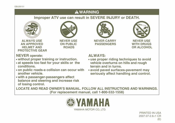
YAMAHA MOTOR CO., LTD.
EBU26151
LOCATE AND READ OWNER’S MANUAL. FOLLOW ALL INSTRUCTIONS AND WARNINGS.(For replacement manual, call 1-800-532-1558)
WARNING
ALWAYS: use proper riding techniques to avoid vehicle overturns on hills and rough terrain and in turns. avoid paved surfaces-pavement may seriously affect handling and control.
Improper ATV use can result in SEVERE INJURY or DEATH.
NEVER operate: without proper training or instruction. at speeds too fast for your skills or the conditions. on public roads-a collision can occur with another vehicle. with a passenger-passengers affect balance and steering and increase risk of losing control.
ALWAYS USE AN APPROVED HELMET AND
PROTECTIVE GEAR
NEVER USE ON PUBLIC
ROADS
NEVER CARRY PASSENGERS
NEVER USE WITH DRUGS OR ALCOHOL
B EE R
B EE R
PRINTED IN USA2007.07-2.6×1 CR
(E)
DIC2342

