ground directional overcurrent relay …...the type jbcg relays are ground directional overcurrent...
TRANSCRIPT
INSTRUCTIONSINSERT BOOKLET
GE K-65 549GEK-49849
GROUND DIRECTIONAL OVERCURRENT RELAYMODEL - 12JBCG61M(-)A
TYPE — JBCG
INTRODUCTION
This instruction booklet along with GEK-49849 form the instructions for the12]BCG61M(-)A relays.
DESCRIPTION
The 12JBCG61M(-)A relays have superseded and reduced the number of forms of the12JBCG61K(-)A relays by using extended range units.
The 12JBCG61M(-)A relays have the same characteristics as the 12JBCG51M(-)A relays but differ only in the arrangement of the target/seal-in unit contacts andin the location of the directional unit contacts. Both target/seal-in unit contacts are connected to separate relay terminals and the directional unit isarranged so that it can be used independently.
These relays were designed primarily for use in the three basic transferred tripping schemes employed for high speed protection of transmission lines.
For this relay see Fig. 1 of this book for the internal connections diagram andFig. 25 of the attached book, GEK-49849, for the outline and panel drilling.
These nLruc-tiins do not purport to ovcr all details or variations in equipment nor to provide for.-o.c, ble contngency to be met in connection with installation, operation or maintenance. Should
further anInnnaton be desired or should particular probleme arise which are not covered sufficiently forthe purchasers purposes, the .sattvr should be referred to the General Electric company.
Te roe Cstenr required the products described hurn meet applicable ANSI, rzsz and NNM4 standards;Lit no surh assurance s qvcn with respect to )al codes and ordinances because they vary greatly.
GENERAL ELECTRIC
1

GEK-6j51
C2
ci OPER D
C3VC4CURR. POL.
crLkJJJ2
2 4
1OC-INSTANT OVERCURRE4T UNIT (TOP)TOC-TIME OVERCURRENT UNIT (MIDDLE)
D-DIRECflONAL UNIT (I?GTTOM)SI—SEAL IN UNIT
Fig. 1 (0275A3277-O) Internal Connections Diagram for the Type JBCG61M(-)A Reay
‘3 ‘5RED
Ju
20
OC
TOC
(2
DPOT.POL.
rSHORT FINGER
2
GEK-49849F
INSTRUCTIONS
TYPES: JBCG51MJBCG51M(-)Y1AJBCG53MJBCG53M(—)Y1AJBCG77M
GROUND DIRECTIONAL OVERCURRENT RELAYS
JBCG52M
JSCG54M
JBCG78M
GE Protection and Control205 Great Valley ParkwayMalvern, PA 19355-1337

GEK-49849
DESCRIPTIONAPPLICATIONRATINGS
TIME OVERCURRENT UNITINSTANTANEOUS OVERCURRENT UNIT
(DIRECTIONALLY CONTROLLED)DIRECTIONAL UNITINSTANTANEOUS UNIT (NON-
DIRECTIONALLY CONTROLLED)TARGET AND SEAL-IN UNITSCONTACTS
OPERATING CHARACTERISTICSPICKUPRESET (TIME OVERCURRENT UNIT)...OPERATING TIMEBURDENS
CONSTRUCTIONDIRECTIONAL UNIT
LOW GRADIENT CONTACTBARREL CONTACT
TIME OVERCURRENT UNITTARGET AND SEAL-IN UNITSINSTANTANEOUS OVERCURRENT UNIT
(DIRECTIONALLY CONTROLLED)INSTANTANEOUS UNIT (NON-
DIRECTIONALLY CONTROLLED)RECEIVING, HANDLING AND
STORAGEACCEPTANCE TESTS
VISUAL INSPECTIONMECHANICAL INSPECTION
TOP UNIT (IOC)MIDDLE UNIT (TOC)BOTTOM UNIT (DIR)TARGET AND SEAL-IN UNIT/
INSTANTANEOUS UNITDRAWOUT RELAYS GENERALPOWER REQUIREMENTS, GENERALTARGET AND SEAL-IN UNITS
PICKUP AND DROPOUT TESTTIME OVERCURRENT UNIT
CURRENT SETTINGTIME SETTINGPICKUP TESTTIME TEST
DIRECTIONAL UNITCURRENT POLARIZATIONPOTENTIAL POLARIZATION
INSTANTANEOUS OVERCURRENT UNIT(DIRECTIONALLY CONTROLLED)
3 PICKUP SETTING4 INSTANTANEOUS UNIT (NON-6 DIRECTIONALLY CONTROLLED)6 INSTALLATION
LOCATION7 MOUNTING8 CONNECTIONS8 INSPECTION
CAUTION8 OPERATION8 TARGET AND SEAL-IN UNIT8 TIME OVERCURRENT UNIT9 DIRECTIONAL UNIT9 INSTANTANEOUS OVERCURRENT UNIT9 (DIRECTIONALLY CONTROLLED)
10 INSTANTANEOUS UNIT (NON-13 DIRECTIONALLY CONTROLLED)13 PERIODIC CHECKS AND ROUTINE13 MAINTENANCE14 TARGET AND SEAL-IN UNIT14 TIME OVERCURRENT UNIT15 DIRECTIONAL UNIT
INSTANTANEOUS OVERCURRENT UNIT15 (DIRECTIONALLY CONTROLLED)
INSTANTANEOUS UNIT (NON-15 DIRECTIONALLY CONTROLLED)
SERVICING16 TARGET AND SEAL—IN UNIT16 TIME OVERCURRENT UNIT16 DISK AND BEARINGS16 CONTACT ADJUSTMENT16 CHARACTERISTICS CHECK17 AND ADJUSTMENTS17 DIRECTIONAL UNIT
BEARINGS17 CUP AND STATOR17 CONTACT ADJUSTMENTS17 BIAS TORQUE ADJUSTMENT18 CLUTCH ADJUSTMENT18 INSTANTANEOUS OVERCURRENT UNIT18 (DIRECTIONALLY CONTROLLED)19 BEARINGS19 CUP AND STATOR20 CONTACT ADJUSTMENTS20 CLUTCH ADJUSTMENT20 INSTANTANEOUS UNIT (NON20 DIRECTIONALLY CONTROLLED)20 CONTACT CLEANING
RENEWAL PARTS21
CONTENTS
21
212121212222222?222222
23
23
23232323
23
242424242424
24252525252626
2727272727
282828
2

GEK-49849
GROUND DIRECTIONAL
OVERCURRENT RELAYS
GROUND DIRECTIONAL OVERCURRENT RELAYS
TYPES: JBCG51M JBCGS2MJBCG51M(— )Y1AJBCG53M JBCGS4MJBCG53M(—)Y1AJBCG77M JBCG78M
DESCRIPTION
The Type JBCG relays are ground directional overcurrent relays that are usedprimarily for the protection of feeders and transmission lines. They are availablewith inverse, very inverse, or extremely inverse time characteristics.
All the LJBCG relays contain a time overcurrent unit of the induction disk type,an instantaneous overcurrent cup type unit, and an instantaneous directional cuptype unit. The directional unit can be potential polarized, current polarized, orboth, and it directionally controls the operation of both the time overcurrent diskunit and the instantaneous cup unit.
Those relays having the designation Y1A following the model number also containa Hi-Seismic instantaneous unit of hinged armature construction. This unit is nondirectional and has a self-contained hand reset target that will show whenever theunit has operated.
Two target seal—in units are provided in each of the relays. The operatingcoil of each of these units respectively is connected in series with the contacts ofthe time overcurrent unit and the instantaneous overcurrent unit. The contacts ofeach seal—in unit respectively are connected in parallel with the contacts of thetime overcurrent unit and the instantaneous overcurrent unit to provide protectionfor them and the associated control spring.
All the JBCG relays are mounted in standard L2 size drawout cases; the outlineand panel drilling dimensions for which are shown in Fig. 5. Internal connectionsfor the relays are shown in Fig. 5, 6 and 7. Typical external connections are shownby Fig. 8 and 9. The JBCG52, JBCG54 and the JBCG78 are double contact relays ofthe 51, 53 and 77 models. The internal connection diagrams are shown in Fig. 26 and27.
octrtctions do not purport to oover all details or variatwns in equipment nor to provide fortv rq ;orJjbi,- sor,tJflgenc4 to bc met n connectnn with installation, operation or maintenance. Should
oforsa t;or be je rd or shc ud p IrtI Ca, jar proh1e arise which are not covered 5uff ciently forthe rohaser ‘s pnrj cc,, tI’ s,attCi .,‘aa’u.? d be referred to the Cneral ,‘otric Company -
I’I) to, txtc’fl reqaar,d ‘h prcciuc” - deserlbCd hr-rein meet applicable ANSI. ISEE and NEMA standards,on’ .J:fl a.sSu: iron is 0 v.0 with r-,-,pec t tc, bell codes and ordinances because they vary greatly -
3
GEK-49849
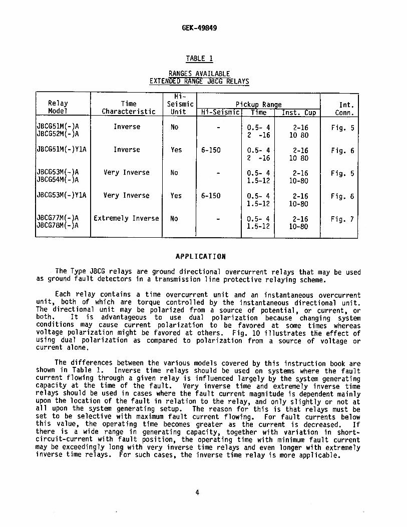
TABLE 1
RANGES AVAILABLEEXTENDED RANGE JBCG RELAYS
Hi-Relay Time Seismic Pckup_Range Tnt.Model Characteristic Unit Hi-Seismic Time Inst. Cup Conn.
JBCG51M(-)A Inverse No - 0.5— 4 2-16 Fig. 5JBCG52M(-)A 2 —16 10 80
JBCG51M(—)Y1A Inverse Yes 6—150 0.5— 4 2—16 Fig. 62 -16 1080
JBCG53M(—)A Very Inverse No — 0.5- 4 2—16 Fig. 5JBCG54M(—)A 1.5-12 10—80
JBCG53M(-)Y1A Very Inverse Yes 6-150 0.5- 4 2—16 Fig. 61.5-12 10-80
JBCG71M(—)A Extremely Inverse No - 0.5— 4 2-16 Fig. 7JBCG78M(-)A 1.5-12 10-80
APPL ICAT ION
The Type JBCG relays are ground directional overcurrent relays that may be usedas ground fault detectors in a transmission line protective relaying scheme.
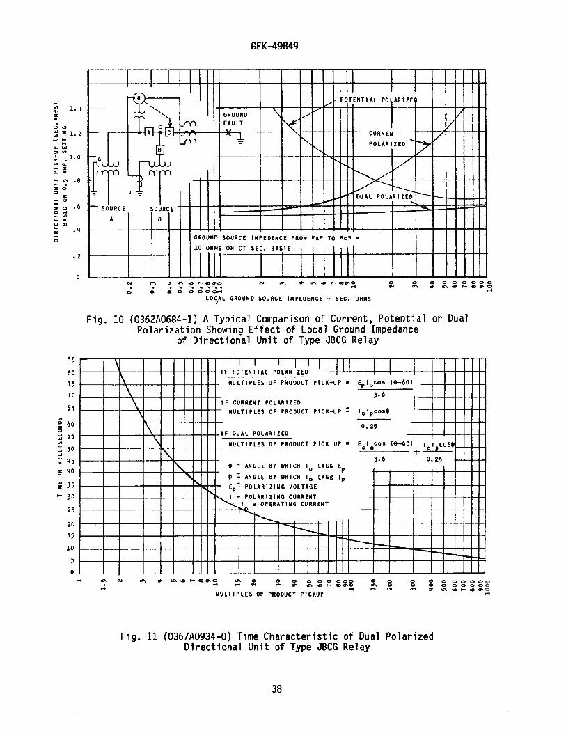
Each relay contains a time overcurrent unit and an instantaneous overcurrentunit, both of which are torque controlled by the instantaneous directional unit.The directional unit may be polarized from a source of potential, or current, orboth. It is advantageous to use dual polarization because changing systemconditions may cause current polarization to be favored at some times whereasvoltage polarization might be favored at others. Fig. 10 illustrates the effect ofusing dual polarization as compared to polarization from a source of voltage orcurrent alone.
The differences between the various models covered by this instruction book areshown in Table 1. Inverse time relays should be used on systems where the faultcurrent flowing through a given relay is influenced largely by the system generatingcapacity at the time of the fault. Very inverse time and extremely inverse timerelays should be used in cases where the fault current magnitude is dependent mainlyupon the location of the fault in relation to the relay, and only slightly or not atall upon the system generating setup. The reason for this is that relays must beset to be selective with maximum fault current flowing. For fault currents belowthis value, the operating time becomes greater as the current is decreased. Ifthere is a wide range in generating capacity, together with variation in shortcircuit—current with fault position, the operating time with minimum fault currentmay be exceedingly long with very inverse time relays and even longer with extremelyinverse time relays. For such cases, the inverse time relay is more applicable.
4

GEK-49849
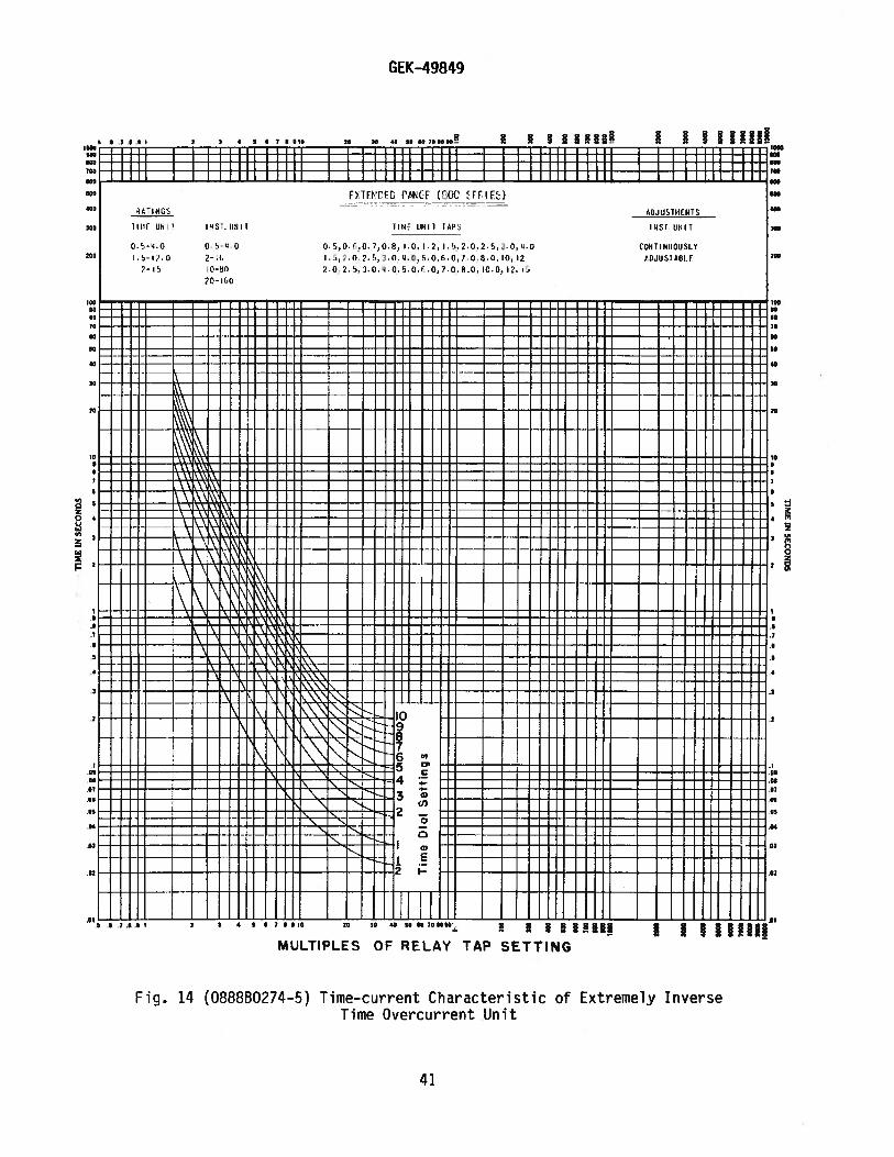
The choice between very inverse and extremely inverse time relays is morelimited than between them and the inverse time relay as they are more nearly alikein their time-current characteristic curves. For grading with fuses, the extremelyinverse time relay should be chosen as the time-current curves more nearly match thefuse curve. Another advantage of the extremely inverse relay is that it is bettersuited than both the inverse and very inverse relays for picking up cold load. Forany given cold load pickup capability, the resulting settings will provide fasterprotection at high fault currents with the extremely inverse relay than with theless inverse relays.
The operating time of the time overcurrent unit for any given value of currentand tap setting is determined by the time dial setting. The operating time isinversely proportional to the current magnitude as illustrated by the time curves inFig. 12, 13 and 14. Note that the current values on these curves are given asmultiples of the tap setting. That is, for a given time dial setting, the time willbe the same for 80 amperes on the eight ampere tap as for 50 amperes on the fiveampere tap, since in both cases, the current is ten times tap setting.
If selective action of two or more relays is required, determine the maximumpossible short-circuit current of the line and then choose a time value for eachrelay that differs sufficiently to insure the proper sequence in the operation ofseveral circuit breakers. Allowance must be made for the time involved in openingeach breaker after the relay contacts close.
The instantaneous cup unit is torque controlled by the directional unit. Whenit is used for direct tripping, it will only be necessary when determining a settingto consider the maximum current that the instantaneous unit will see for a fault atthe remote terminal. The instantaneous cup unit has low transient overreach. Itshould be set with a margin of at least ten percent above the maximum current for aremote fault neglecting transient overreach.
The Y1A relays contain a Hi—Seismic instantaneous overcurrent unit. This unitmay be set high to provide direct tripping for heavy internal faults. Indetermining the setting for this unit when it is used for direct tripping, it willbe necessary to consider the maximum external fault for faults at each end of theline because the unit is non—directional. The unit should be set with a suitablemargin above the maximum external fault taking into account the effects of transientoverreach as illustrated in Fig. 17.
The red jumper leads between studs 18 and 19 and 19 and 20 are located insidethe case on the cradle block and may be removed to provide external torque controlof the time overcurrent unit (TOC) and the instantaneous overcurrent unit (IOC)respectively. If external torque control of either or both units is required,remove the red jumper lead associated with the unit(s) to be controlled, and connectthe external control contacts between the appropriate studs. Note that the unitswill still be torque controlled by the directional unit in addition to the externalcontrol.
5

GEK-49849
RATINGS
The JBCG relays described in this instruction book are available in 50 and 60hertz models. The TOC (time overcurrent) units have extended (eight—to-one) rangesimilar to the 800 series IAC relays. The directionally controlled bC(instantaneous overcurrent) units also have extended (eight-to-one) range. The non—directionally controlled IOC units, when used (see Table 1), have a 25-to—oneextended range. Ratings of the operating current circuits of the TOC units, thedirectionally controlled bC units and the directional units are shown individually.However, since all operating current circuits are normally connected in series, theoperating coil ratings of all three units should be considered in determining therating of the entire operating circuit.
TIME OVERCURRENT UNIT
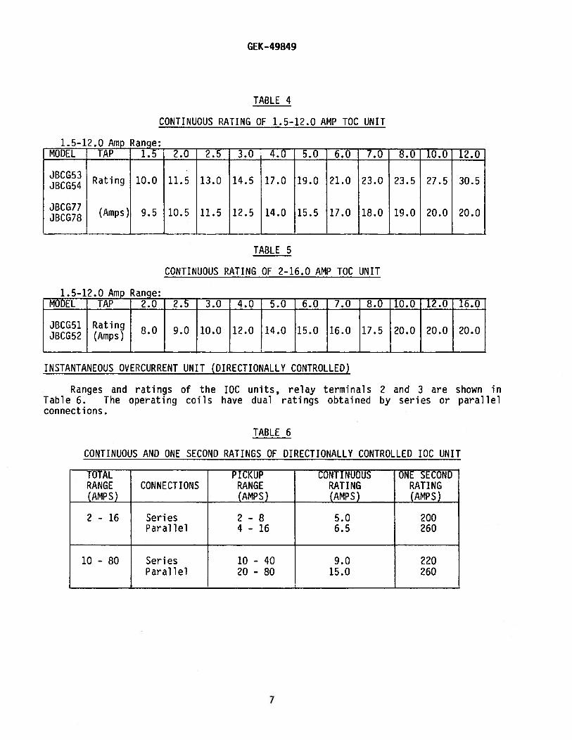
The one second ratings of the TOC units are given in Table 2. The continuousratings for the various taps of each model and current range are given in Tables 3,4 and 5.
TABLE 2ONE SECOND RATING OF TOC UNITS
RELAY RANGE ONE SECONDMODEL (AMPS) RATING (AMPS)
JBCG51 0.5 — 4 70JBCG52 2 - 16 260
JBCG53 0.5 - 4 140JBCG54 1.5 - 12 260
JBCG77 0.5 - 4 125JBCG78 1.5 — 12 260
CONTINUOUSTABLE 3
RATING OF 0.5-4.0 AMP TOC UNIT
0.5-4.0 AMP RANGE:MODEL TAP 0.5 0.6 0.7 0.8 1.0 1.? 1.5 2.0 2.5 3.0 4.0
J8CG51 1.6 1.8 2.0 2.1 2.3 2.7 3.0 3.5 4.0 4.5 5.0JBCGS2 Rating
(Amps)JBCG53 LO 4.5 5.5 5.5 6.0 7.0 7.5 9.0 10.0 11.0 13.0JBCG54
JBCG17 3.5 3.7 4.0 4.5 5.0 5.5 6.0 7.0 8.0 9.0 10.0JBCG78
6
GEK-49849
TABLE 4
CONTINUOUS RATING OF 1.5-12.0 AMP TOC UNIT
1.5—12.0 Amp Range:MODEL TAP 1.5 2.0 2.5 3.0 4.0 5.0 6.0 7.0 8.0 10.0 12.0
JBCG53JBCG54 Rating 10.0 11.5 13.0 14.5 17.0 19.0 21.0 23.0 23.5 27.5 30.5
JBCG77JBCG7S (Amps) 9.5 10.5 11.5 12.5 14.0 15.5 17.0 18.0 19.0 20.0 20.0
— - — ———--- — -_____
TABLE 5
CONTINUOUS RATING OF 2-16.0 AMP TOC UNIT
1.5—12.0 Amp Range:MODEL TAP 2.0 2.5 3.0 4.0 I 5.0 6.0 7.0 8.0 10.0 12.0 16.0I I I I
JBCG51 Rating 8 0 9.0 10.0 12.0 14.O 15.0 16.0 17.5 20.0 20.0 20.0JBCG52 (Amps)
INSTANTANEOUS OVERCURRENT UNIT (DIRECTIONALLY CONTROLLED)
Ranges and ratings of the IOCTable 6. The operating coils haveconnections.
units, relay terminals 2 and 3 are shown indual ratings obtained by series or parallel
TABLE 6
CONTINUOUS AND ONE SECOND RATINGS OF DIRECTIONALLY CONTROLLED IOC UNIT
CONT I NUOUSRATING(AMPS)
5.06.5
ONE SECONDRATING(AMPS)
200260
TOTALRA N GE(AMPS)
CONNECTIONS
2 - 16
PICKUPRA N GE(AMPS)
SeriesParallel
2-84 - 16
10 - 80 Series 10 - 40 9.0 220Parallel 20 - 80 15.0 260
7

GEK-49849
DIRECTIONAL UNIT
The directional unit operating coil, relay terminals 5 and 6, has a six amperecontinuous rating and a 200 ampere one second rating. The current polarizing circuit,terminals 7 and 8, has a five ampere continuous rating and a 150 ampere one secondrating. The potential polarizing coil, terminals 9 and 10, will withstand 120 voltscontinuously and 360 volts for 60 seconds.
INSTANTANEOUS UNIT (NON—DIRECTIONALLY CONTROLLED)
The instantaneous unit coil is tapped for operation on either one of two ranges (Hor L). Selection of the high or low range is determined by the position of leads T andE at terminal 15. See Table 7 and the applicable internal connections referenced inTable 1. For the H range, connect lead T to terminal 15 and lead E to the auxiliaryterminal that is mounted on terminal 15. For range L, reverse leads T and E.
TABLE 7
CONTINUOUS AND ONE SECOND RATINGS OF NON-DIRECTIONALLY CONTROLLED lOG UNIT
** CONTINUOUS ONE SECONDINSTANTANEOUS RANGE RATING RATING
UNIT (AMPS) RANGE (AMPS) (AMPS) (AMPS)
6 - 150 L 6 - 30 10.2 260H 30 - 150 19.6
** The range is approximate, which means that 6—30, 30-150 may be 6-2828-150. There will always be at least one ampere overlap between themaximum L setting and the minimum H setting. Whenever possible,always select the higher range, since it has the higher continuousrating.
TARGET AND SEAL-IN UNITS
The rating and impedance of the seal-in unit for the 0.2/0.6 and two ampere tapsare given in Table 8. The tap setting used will depend on the current drawn by the tripcoil.
The 0.2/0.6 ampere tap is for use with trip coils which operate on currentsranging from 0.2/0.6 up to 2.0 amperes, at the minimum control voltage. IF this tap isused with trip coils requiring more than two amperes, there is a possibility that theresistance of 8.30 ohms will reduce the current to so low a value that the breaker willnot be tripped.
The two ampere tap should be used with trip coils that take two amperes or more atminimum control voltage, provided the current does not exceed 30 amperes at the maximumcontrol voltage. If the tripping current exceeds 30 amperes, the connections should bearranged so that the induction unit contacts will operate an auxiliary relay which inturn energizes the trip coil or coils. On such an application, it may be necessary toconnect a loading resistor in parallel with the auxiliary relay coil to allow enoughcurrent to operate the target seal-in unit.
8

GEK-49849
TABLE 8
SEAL-IN UNIT RATINGS
______
TAP0.2 2.0 0.6 2.0
DC Resistance +10% 8.3 0.24 0.78 0.18Minimum OperatTng, “I” (+) (—)40% 0.2 2.0 0.6 2.0Carry “I” Continuous (Amps) 0.37 2.3 1.2 2.6Carry 30 Amps for (Seconds) 0.05 2.2 0.5 3.5Carry 10 Amps for (Seconds) 0.45 20 5.0 3060 Hz “Z” (Ohms) 50 0.65 6.2 0.65
CONTACTS
The current-closing rating of the induction unit contacts is 30 amperes forvoltages not exceeding 250 volts. Their current—carrying rating is limited by thetap rating of the seal—in unit.
OPERATING CHARACTERISTICS
PICKUP
When potential polarized, the directional unit will pick up at 3.6 volt—amperesat the maximum torque angle of 60 degrees lag (current lags voltage). When currentpolarized, it will pick up at approximately 0.5 ampere with the operating aridpolarizing coils connected in series. The performance of the unit with simultaneouscurrent and potential polarization is typified in Fig. 10.
The current required to close the time overcurrent unit contacts will be withinfive percent of the tap screw setting. The pickup of the directionally controlledinstantaneous overcurrent unit can be adjusted over an eight—to-one range asindicated in Table 6.
RESET (TIME OVERCURRENT UNIT)
Inverse time overcurrent units reset at 90 percent of the minimum pickupcurrent, very inverse time units at 80 percent, and extremely inverse time units at85 percent.
When the relay is de-energized, the time required for the disk to completelyreset to the number 10 time dial position is approximately six seconds for inversetime relays and 60 seconds for very inverse time and extremely inverse-time relays.
OPERATING TIME
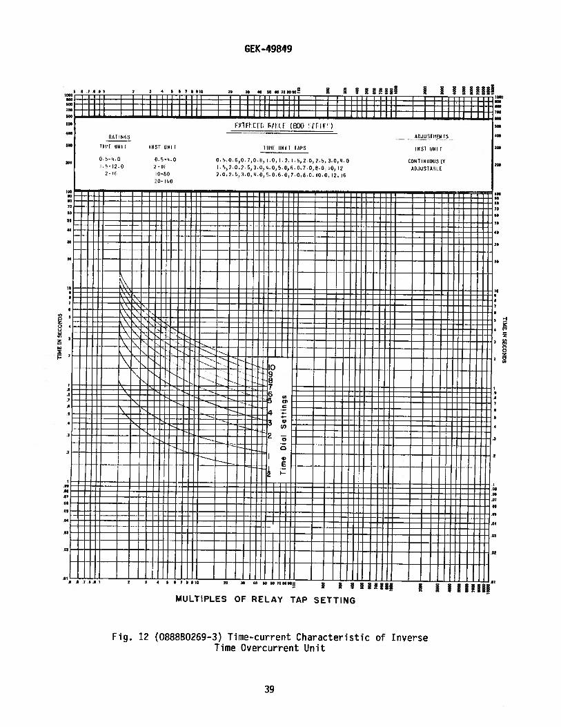
The time curve for the directional unit is shown in Fig. 11.
The time curves of the TOC units are shown in Fig. 12, 13 and 14, respectivelyfor inverse-time relays, very inverse-time relays and extremely inverse-time relays.
9

GEK-49849
For the same operating conditions, the relay will operate repeatedly within one ortwo percent of the same time.
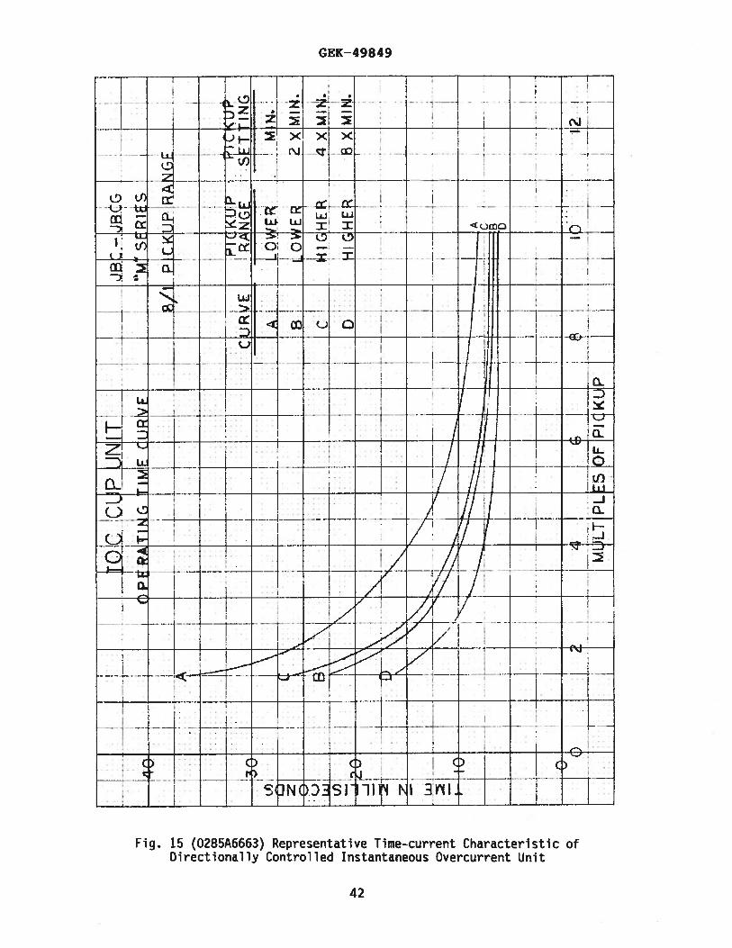
The time curves for the directionally controlled IOC units are shown in Fig.15.
The time—current characteristic of the Hi-Seismic non—directionally controlledbC unit is shown by Fig. 16 and its transient overreach characteristic is shown byFig. 17.
BURDENS
The burden of the potential polarizing circuit at 50 hertz is:
VA = 1.04
P.F. = 0.851
The capacitive burden of the potential polarizing circuit of the directionalunit at 60 cycles and 120 volts is 10 volt-amperes at 086 power factor. Table 9gives the current circuit burdens of the directional unit.
Table 10 gives the total burden of the time overcurrent unit plus theinstantaneous overcurrent unit. Table 11 gives the burden of the non-directionallycontrolled instantaneous overcurrent unit. Ordinarily, the potential circuit is inthe open corner of broken delta potential transformers and the current circuits arein the residual circuits of current transformers. The burden is, therefore, onlyimposed for the duration of the ground fault and need be considered only for thisbrief period.
TABLE 9
DIRECTIONAL UNIT CURRENT CIRCUIT BURDEN AT 50 HERTZ AND FIVE AMPERES
CIRCUIT Z (OHMS) VA P.F. WATTS
Operating 0.423 10.57 0.588 6.22
Polarizing 0.236 5.90 0.964 5.70
DIRECTIONAL UNIT CURRENT CIRCUIT BURDEN AT 60 CYCLES AND FIVE AMPERES
CIRCUIT Z (OHMS) VA P.F. WATTS
Operating 0.46 12.0 0.52 6.24
Polarizing 0.24 6.0 0.95 5..]
10

GEK-49849
TABLE 10
BURDENS OF OVERCURRENT UNITS (TIME AND INSTANTANEOUS)AT 50 CYCLES
BURDENS OF OVERCURRENT UNITS (TIME AND INSTANTANEOJAT 60 CYCLES
BURDEN OHMS(Z)
THREE TENRANGE BURDENS AT MINIMUM PICKUP TIMES TIME VA
TIME TOC IOC IOC UNIT MINIMUM TAP OF TOC UNIT MIN. MIN. AT 5CHAR’C UNIT UNIT CONNECTIONS R Jx +VA PF P.U. P.U. AMPS
2-16 Series 2-8 5.84 21.57 22.3 5.6 0.26 11.38 6.90 559Parallel 4-16 5.65 21.10 21.8 5.5 0.26 10.88 5.11 546
0.5-4
10—80 Series 10—40 5.68 21.14 21.9 5.5 0.26 10.93 5.16 547Parallel 20—80 5.61 21.01 21.7 5.4 0.26 10.78 5.02 544
IN VERSE
2-16 Series 2-8 0.61 2.01 2.10 8.4 0.29 1.27 0.85 53Parallel 4-16 0.42 1.54 1.60 6.4 0.26 0.76 0.43 40
2-16
10-80 Series 10-40 0.45 1.58 1.65 6.6 0.27 0.81 0.48 41Parallel 20-80 0.38 1.45 1.50 6.0 0.25 0.67 0.34 38
TIMECHAR ‘ C
RANGETOC IOCUNIT UNIT
IOC UNITCONNECTIONS
2-16
O.5-4
BURDEN OHMS(z)
BURDENS AT MINIMUM PICKUPMINIMUM TAP OF TOC UNITR Jx ** z +VA
THREETIMESMIN.P.U.PF
TENTIMEMIN.Pai.
INVERSE
Series 2—8 5.84 17.25 18.21 4.55 O.32( 9.29 5.63 455Parallel 4-16 5.65 16.88 17.80 4.45 0.317 8.88 4.17 445
VAAT 5AMPS
2-16
10—80 Series 10-40 5.68 16.91 17.83 4.46 0.318 8.91 4.20 446Parallel 20-80 5.61 16.80 17.71 4.42 0.317 8.80 4.09 443
2-16 Series 2-8 0.61 1.61 1.72 6.88 0.354 1.04 0.69 43Parallel 4-16 0.42 1.23 1.299 5.19 0.323 0.617 0.35 32.5
10-80 Series 10—40 0.45 1.26 1.34 5.35 0.336 0.660 0.39 33.5Parallel 20—80 0.38 1.16 1.22 4.88 0.311 0.545 0.216 30.5
11

GEK -49849
TABLE 10 (Continued)
BURDEN OHMS
THREE TENRANGE BURDENS AT MINIMUM PICKUP TIMES TIME VA
TIME TOC bC IOC UNIT MINIMUM TAP OF TOC UNIT MIN. MIN. AT 5CHARC UNIT UNIT CONNECTIONS R J ** +VA PF P.U. P.U. AMPS
2-16 Series 2—8 1.64 4.47 4.76 1.2 0.35 4.83 3.43 119Parallel 4—16 1.45 4.00 4.25 1.1 0.34 4.31 3.01 106
0.5-410—80 Series 10—40 1.48 4.04 4.31 1.1 0.34 4.36 3.06 108
VERY Parallel 20—80 1.41 3.91 4.15 1.0 0.34 4.21 2.92 104IN VERSE
2—16 Series 2-8 0.47 1.10 1.20 2.7 0.39 1.20 0.53 30Parallel 4-16 0.28 0.63 0.69 1.6 0.41 0.69 0.47 11
1.5—1210-80 Series 10-40 0.31 0.61 0.74 1.7 0.42 0.74 0.52 19
Parallel 20-80 0.24 0.54 0.59 1.3 0.41 0.59 0.38 15
2-16 Series 2—8 1.04 1.95 2.21 0.6 0.47 2.21 2.12 55Parallel 4—16 0.85 1.48 1.71 0.4 0.50 1.71 1.71 43
0.5-4EX- 10-80 Series 10-40 0.88 1.52 1.76 0.4 0.50 1.76 1.76 44
TREMEL Parallel 20-80 0.81 1.39 1.61 0.4 0.50 1.61 1.61 40INVERSE
2-16 Series 2-8 0.33 0.12 0.79 1.8 0.42 0.79 0.70 20Parallel 4-16 0.13 0.25 0.28 0.6 0.46 0.28 0.28 7
1.5—1210-80 Series 10-40 0.16 0.29 0.33 0.7 0.49 0.33 0.33 8
Parallel 20-80 0.10 0.16 0.19 0.4 0.53 0.19 0.19 5
**The impedance values given are those for the minimum tap of each relay.The impedance for other taps, at pickup current (tap rating), variesinversely approximately as the square of the current rating. Example:for the very inverse relays, 1.5/12 amperes, with impedance of the1.5 ampere tap of 1.20 ohms, the impedance of the three ampere tap, atthree amperes, is approximately (1.5/3)2 X 1.20 = 0.3 ohms.
+Some companies list relay burdens only as the volt-ampere input tooperate at mininiurn pickup. This column is included so a direct comparison can be made. It should not be used in calculating volt-ampereburdens in a CT secondary circuit, since the burden at five amperes isused for this purpose.
Calculated from burden at minimum pickup.
12
GEK-49849
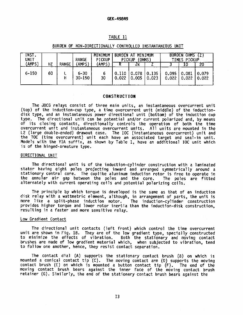
TABLE 11
BURDEN OF NON-DIRECTIONALLY CONTROLLED INSTANTANEOUS UNIT
INST. MINIMUM BURDEN AT MINIMUM BURDEN OHMS (Z)UNIT RANGE PICKUP PICKUP__(OHMS) TIMES_PICKUP(AMPS) HZ RANGE (AMPS) (AMPS) R Jx Z 3 10 20
6-150 60 L 6-30 6 0.110 0.078 0.135 0.095 0.081 0.079H 30-150 30 0.022 0.005 0.023 0.022 0.022 0.02?
CONSTRUCTION
The JBCG relays consist of three main units, an instantaneous overcurrent unit(top) of the induction-cup type, a time overcurrent unit (middle) of the induction-disk type, and an instantaneous power directional unit (bottom) of the induction cuptype. The directional unit can be potential and/or current polarized and, by meansof its closing contacts, directionally controls the operation of both the timeovercurrent unit and instantaneous overcurrent units. All units are mounted in theL2 (large double—ended) drawout case. The IOC (instantaneous overcurrent) unit andthe TOC (time overcurrent) unit each have an associated target and seal—in unit.Models with the ViA suffix, as shown by Table 1, have an additional IOC unit whichis of the hinged-armature type.
DIRECTIONAL UNIT
The directional unit is of the induction—cylinder construction with a laminatedstator having eight poles projecting inward and arranged symmetrically around astationary central core. The cuplike aluminum induction rotor is free to operate inthe annular air gap between the poles and the core. The poles are fittedalternately with current operating coils and potential polarizing coils.
The principle by which torque is developed is the same as that of an inductiondisk relay with a wattmetric element, although, in arrangement of parts, the unit ismore like a split—phase induction motor. The induction—cylinder constructionprovides higher torque and lower rotor inertia than the induction-disk construction,resulting in a faster and more sensitive relay.
Low Gradient Contact
The directional unit contacts (left front) which control the time overcurrentunit are shown in Fig. 18. They are of the low gradient type, specially constructedto minimize the effects of vibration. Both the stationary and moving contactbrushes are made of low gradient material which, when subjected to vibration, tendto follow one another, hence, they resist contact separation.
The contact dial (A) supports the stationary contact brush (B) on which ismounted a conical contact tip (C). The moving contact arm (0) supports the movingcontact brush (E) on which is mounted a button contact tip (F). The end of themoving contact brush bears against the inner face of the moving contact brushretainer (G). Similarly, the end of the stationary contact brush bears against the
13

GEK-49849
inner face of the stationary contact brush retainer (H). The stationary contactsupport (K) and the contact dial are assembled together by means of a mounting screw(L) and two lock—nuts (M).
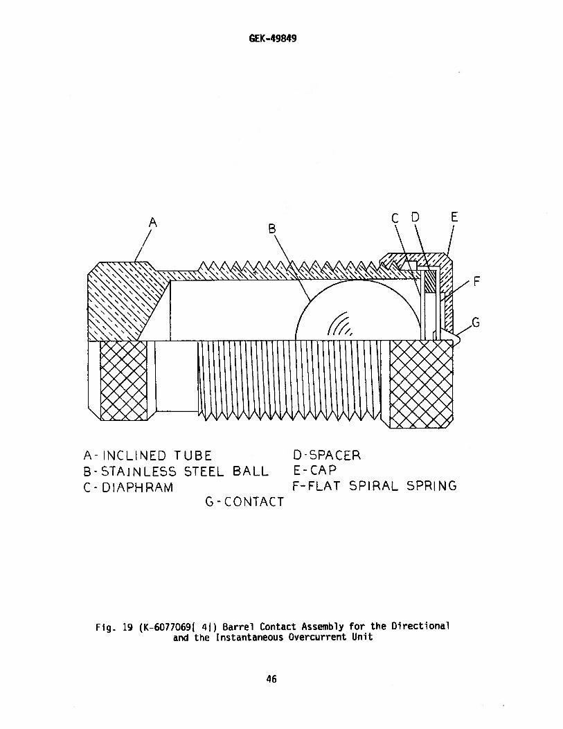
Barrel Contact
The directional unit contacts (right rear) which control the instantaneousovercurrent unit, are shown in Fig. 19. They are specially constructed to suppressbouncing. The stationary contact (G) is mounted on a flat spiral spring (F) backedup by a thin diaphragm (C). These are both mounted in a slightly inclined tube (A).A stainless steel ball (B) is placed in the tube before the diaphragm is assembled.When the moving contact hits the stationary contact, the energy of the former isimparted to the latter and thence to the ball, which is free to roll up the inclinedtube. Thus the moving contact comes to rest with substantially no rebound orvibration. To change the stationary contact mounting spring, remove the contactbarrel and sleeve as a complete unit after loosening the screw at the front of thecontact block. Unscrew the cap (E). The contact and its flat spiral mountingspring may then be removed.
TIME OVERCURRENT UNIT
The inverse time and very inverse time overcurrent units consist of a tappedcurrent operating coil wound on a U-magnet iron structure. The tapped operatingcoil is connected to taps on the tap block. The U-magnet contains wound shadingcoils which are connected in series with a directional unit contact. When powerflow is in such a direction as to close the directional unit contacts, the shadingcoils act to produce a split-phase field which, in turn, develops torque on theoperating disk.
The extremely inverse time overcurrent unit is of the wattmetric type similarto that used in watthour meters except as follows: the upper portion of the ironstructure has two concentric windings on the middle leg of the magnetic circuit.One of these is a tapped current winding connected to taps on the tap block; theother is a floating winding which is connected in series with the directional unitcontacts, a resistor, a capacitor and the two coils on the lower legs of themagnetic circuit. When power flow is in such a direction as to close a directionalunit contact, the unit develops torque on the operating disk.
The disk shaft carries the moving contact which completes the trip circuit whenit touches the stationary contact or contacts. The shaft is restrained by a spiralspring to give the proper contact—closing current, and its motion is retarded by apermanent magnet acting on the disk to produce the desired time characteristic. Thevariable retarding force resulting from the gradient of the spiral spring iscompensated by the spiral shape of the induction disk, which results in an increaseddriving force as the spring winds up.
The torque control circuits of both the time overcurrent and instantaneousovercurrent units are wired to terminals on the relay contact block. Theseterminals are shorted together by internally connected red jumper leads when therelays leave the factory (see Fig. 5 to 7 inclusive). If external torque control isdesired, these jumper leads should be removed.
14

GEK-49849
TARGET AND SEAL-IN UNITS
The seal-in units for both the TOC and ICC contacts of the JBCG51M—5?M, JBCG53M—54M and JBCG77M-78M relays are mounted on the IOC middle unit. On the JBCG51M(—)Y1Aand JBCG53M(-)Y1A relays, the right-hand seal-in unit is replaced by the non-directionally controlled IOC unit and the seal—in unit is moved to the left side of thedirectional (lower) unit.
The left seal-in unit operates in conjunction with the timer overcurrent unitcontacts and is labeled “TIME.” Its coil is in series and its contacts in parallel withthe main contacts of the time overcurrent unit so that when the main contacts close,the seal-in unit will pick up and seal in around the main contact.
The right seal-in unit, labeled “INST” operates in conjunction with theinstantaneous overcurrent unit. Its coil is in series with the instantaneous unitcontact and a contact of the directional unit, and its contact is connected to seal inaround these two contacts when the unit operates.
Both seal—in units are equipped with targets which are raised into view when theunit operates. These targets latch and remain exposed until manually released by meansof the button projecting below the lower—left corner of the cover.
INSTANTANEOUS OVERCURRENT UNIT (DIRECTIONALLY CONTROLLED)
The instantaneous overcurrent unit is similar in construction to the directionalunit described above, differing only in coil turns and connections. The four cornercoils consist of two windings, an inner winding consisting of a large number of turnsof fine wire, and an outer winding having a few turns of heavy wire. The outer windingsof the corner coils are connected either in series or in parallel with the side coils bytap links provided on the relay; these series or parallel combinations are connected inseries with the operating coil of the TOC unit. The inner windings of the corner coilsare all connected in series, and in turn are connected in series with a capacitor and acontact of the directional unit. This circuit thus controls the torque of theinstantaneous overcurrent unit. When the directional unit contacts are open, theinstantaneous overcurrent unit will develop no torque. When the directional unitcontacts are closed, the instantaneous overcurrent unit will develop torque inproportion to the square of the current.
The instantaneous overcurrent unit develops operating torque in a directionopposite to that of the directional unit. This makes the relay less susceptible to theeffects of shock.
INSTANTANEOUS UNIT (NON-DIRECTIONALLY CONTROLLED)
The IOC unit is a small hinged armature type instantaneous element and is mountedon the right side of the TOC unit. The IOC element operates over a 25-to-one totalrange obtained by using a tapped coil which provides a five-to-one low range and afive—to—one high range; this combination provides the 25-to—one total range. When thecurrent reaches a predetermined value, the instantaneous element operates closing itscontact circuit and raising its target into view. The target latches in the exposedposition until it is released. The same button that releases the target seal—in unitalso releases the target of the instantaneous unit.
15

GEK-49849
RECEIVING, HANDLING AND STORAGE
These relays, when not included as part of a control panel will be shipped incartons designed to protect them against damage. Immediately upon receipt of arelay, examine it for any damage sustained in transit. If injury or damageresulting from rough handling is evident, file a damage claim at once with thetransportation company and promptly notify the nearest General Electric ApparatusSales Office.
Reasonable care should be exercised in unpacking the relay in order that noneof the parts are injured or the adjustments disturbed.
If the relays are not to be installed immediately, they should be stored intheir original cartons in a place that is free from moisture, dust and metallicchips. Foreign matter collected on the outside of the case may find its way insidewhen the cover is removed, and cause trouble in the operation of the relay.
ACCEPTANCE TESTS
Immediately upon receipt of the relay an inspection and acceptance test shouldbe made to ensure that no damage has been sustained in shipment and that the relaycalibrations have not been disturbed. If the examination or the test indicates thatreadjustment is necessary, refer to the section on SERVICING.
These tests may be performed as part of the installation or acceptance tests atthe discretion of the user.
Since most operating companies use different procedures for acceptance andinstallation tests, the following section includes all applicable tests that may beperformed on these relays.
VISUAL INSPECTION
Check the nameplate stamping to ensure that the model number and rating of therelay agree with the requisition.
Remove the relay from its case and check that there are no broken or crackedmolded parts or other signs of physical damage and that all screws are tight. Checkthat the shorting bars are in the proper location(s) as shown by the internalconnections diagrams, Fig. 5 to 7 inclusive, and that the main brush is properlyformed to contact the shorting bar.
MECHANICAL INSPECTION
Top Unit (IOC)
1. The rotating shaft end play should be 0.015—0.020 inch.2. The contact gap should be 0.075-0.080 inch.3. There should be no noticeable friction in the rotating structure.4. With the relay well leveled and in its upright position, the contact should be
open and resting against the backstop.
16
GEK-49849
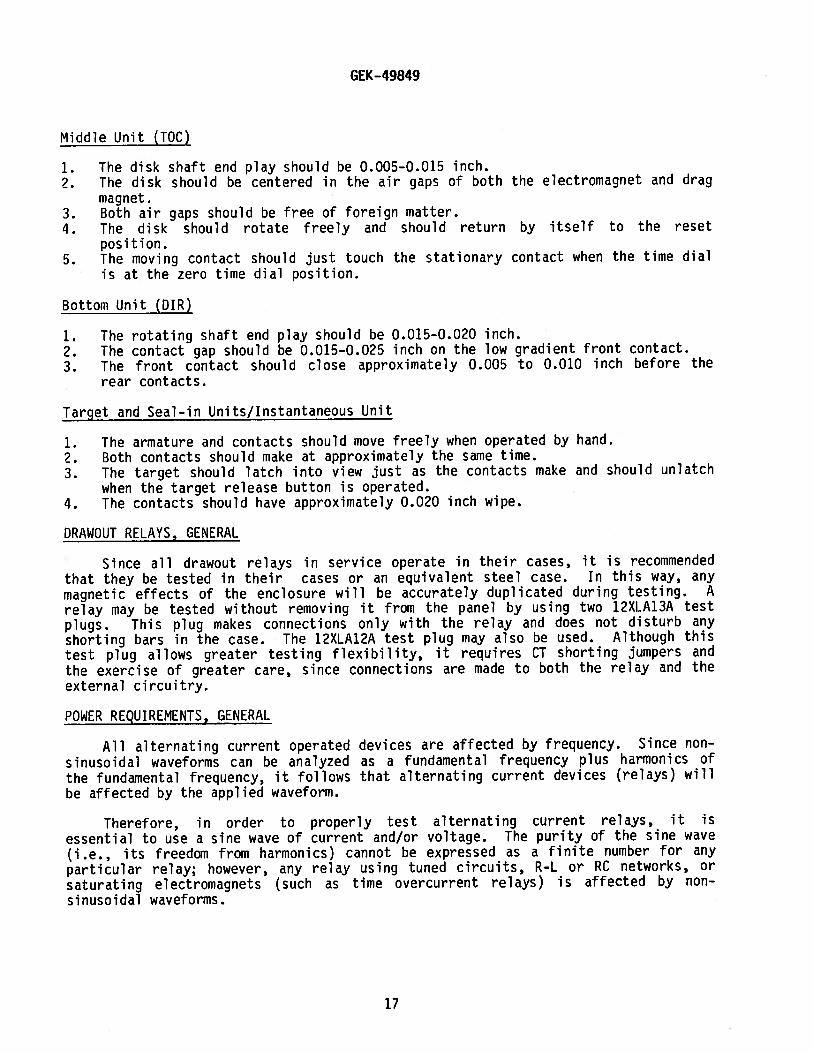
Middle Unit (TOC)
1. The disk shaft end play should be 0.005-0.015 inch.2. The disk should be centered in the air gaps of both the electromagnet and drag
magnet.3. Both air gaps should be free of foreign matter.4. The disk should rotate freely and should return by itself to the reset
position.5. The moving contact should just touch the stationary contact when the time dial
is at the zero time dial position.
Bottom Unit (DIR)
1. The rotating shaft end play should be 0.015-0.020 inch.2. The contact gap should be 0.015—0.025 inch on the low gradient front contact.3. The front contact should close approximately 0.005 to 0.010 inch before the
rear contacts.
Target and Seal-in Units/Instantaneous Unit
1. The armature and contacts should move freely when operated by hand.2. Both contacts should make at approximately the same time.3. The target should latch into view just as the contacts make and should unlatch
when the target release button is operated.4. The contacts should have approximately 0.020 inch wipe.
DRAWOUT RELAYS, GENERAL
Since all drawout relays in service operate in their cases, it is recommendedthat they be tested in their cases or an equivalent steel case. In this way, anymagnetic effects of the enclosure will be accurately duplicated during testing. Arelay may be tested without removing it from the panel by using two 12XLA13A testplugs. This plug makes connections only with the relay and does not disturb anyshorting bars in the case. The 12XLA12A test plug may also be used. Although thistest plug allows greater testing flexibility, it requires CT shorting jumpers andthe exercise of greater care, since connections are made to both the relay and theexternal circuitry.
P04ER REQUiREMENTS, GENERAL
All alternating current operated devices are affected by frequency. Since non-
sinusoidal waveforms can be analyzed as a fundamental frequency plus harmonics ofthe fundamental frequency, it follows that alternating current devices (relays) willbe affected by the applied waveform.
Therefore, in order to properly test alternating current relays, it is
essential to use a sine wave of current and/or voltage. The purity of the sine wave(i.e., its freedom from harmonics) cannot be expressed as a finite number for anyparticular relay; however, any relay using tuned circuits, R—L or RC networks, or
saturating electromagnets (such as time overcurrent relays) is affected by nonsinusoidal waveforms.
17
GEK-49849
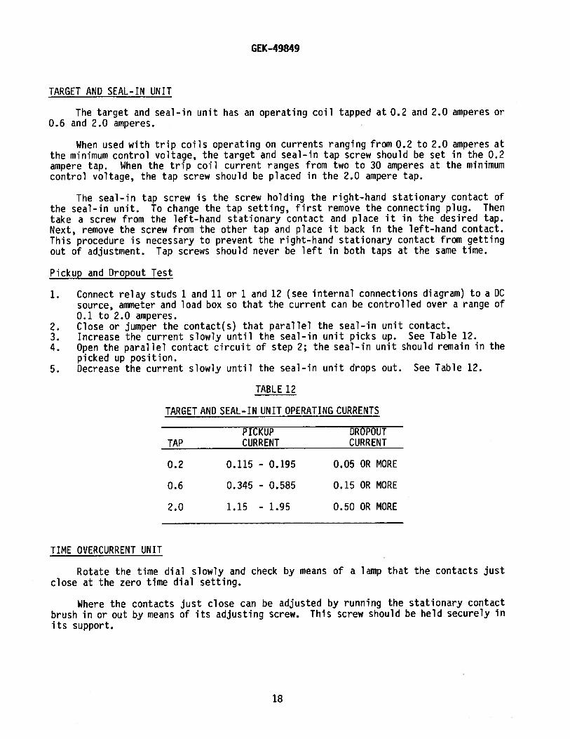
TARGET AND SEAL-IN UNIT
The target and seal-in unit has an operating coil tapped at 0.2 and 2.0 amperes or0.6 and 2.0 amperes.
When used with trip coils operating on currents ranging from 0.2 to 2.0 amperes atthe minimum control voltage, the target and seal—in tap screw should be set in the 0.2ampere tap. When the trip coil current ranges from two to 30 amperes at the minimumcontrol voltage, the tap screw should be placed in the 2.0 ampere tap.
The seal-in tap screw is the screw holding the right-hand stationary contact ofthe seal—in unit. To change the tap setting, first remove the connecting plug. Thentake a screw from the left-hand stationary contact and place it in the desired tap.Next, remove the screw from the other tap and place it back in the left-hand contact.This procedure is necessary to prevent the right-hand stationary contact from gettingout of adjustment. Tap screws should never be left in both taps at the same time.
Pickup and Dropout Test
1. Connect relay studs 1 and 11 or 1 and 12 (see internal connections diagram) to a DCsource, ammeter and load box so that the current can be controlled over a range of0.1 to 2.0 amperes.
2. Close or jumper the contact(s) that parallel the seal-in unit contact.3. Increase the current slowly until the seal-in unit picks up. See Table 12.4. Open the parallel contact circuit of step 2; the seal-in unit should remain in the
picked up position.5. Decrease the current slowly until the seal-in unit drops out. See Table 12.
TABLE 12
TARGET AND SEAL-IN UNIT OPERATING CURRENTS
PICKUP DROPOUTTAP CURRENT CURRENT
0.2 0.115 - 0.195 0.05 OR MORE
0.6 0.345 - 0.585 0.15 OR MORE
2.0 1.15 - 1.95 0.50 OR MORE
TIME OVERCURRENT UNIT
Rotate the time dial slowly and check by means of a lamp that the contacts justclose at the zero time dial setting.
Where the contacts just close can be adjusted by running the stationary contactbrush in or out by means of its adjusting screw. This screw should be held securely inits support.
18

GEK-49849
With the contacts just closing at No. 0 time setting, there should be sufficientgap between the stationary contact brush and its metal backing strip to ensureapproximately 1/32 inch wipe.
Current Setting
The minimum current at which the time overcurrent unit will close its contacts isdetermined by the position of the plug in the tap block. The tap plate on this block ismarked in amperes, as shown in Tables 3, 4 and 5.
When the tap setting is changed with the relay in service, the following proceduremust be followed: (1) Remove the connecting plug; this de-energizes the relay andshorts the current transformer secondary winding. (2) Remove the tap screw and placeit in the tap marked for the desired pickup current. (3) Replace the connecting plug.
The minimum current required to rotate the disk slowly and to close the contactsshould be within five percent of the value marked on the tap plate for any tap settingand time dial position. If this adjustment has been disturbed, it can be restored bymeans of the spring adjusting ring. The ring can be turned by inserting a screw driverblade in the notches around the edge. By turning the ring, the operating current of theunit can be brought into agreement with the tap setting employed. This adjustment alsopermits any desired setting to be obtained intermediately between the available tapsettings.
Pickup adjustment by means of the control spring applies to the JBCG51 and JBCG53relays. A different procedure applies to the JBCG77 relays. For the JBC677 relays,the pickup of the unit for any current tap setting is adjusted by means of the variableresistor in the phase—shifting circuit. This adjustment also permits any desiredsetting intermediately between the various tap settings to be obtained. The controlspring is prewound approximately 660 degrees with the contacts just closed. Furtheradjustment of this setting is seldom required; if it is required, because of theinsufficient range of the variable resistor, it should never be necessary to wind upthe control spring adjuster more than 30 degrees (one notch) or unwind it more than 90degrees (three notches) from the factory setting.
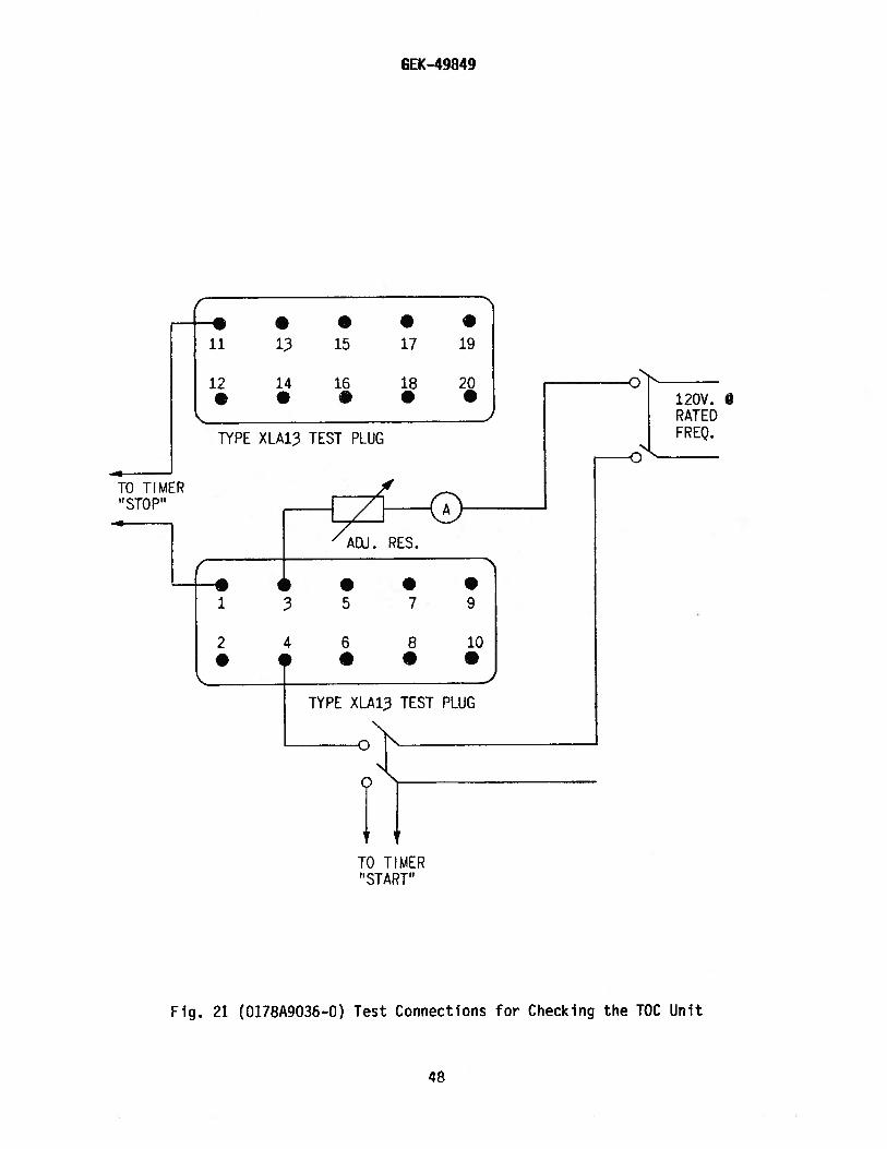
Test connections for making pickup and time checks on the time over—current unitare shown in Fig. 21. Use a source of 120 volts or greater with good wave form andconstant frequency. Stepdown transformers or phantom loads should not be employed intesting induction relays since their use may cause a distorted wave form. The contactin the wound shading coil circuit marked D, see internal connection diagram, must beblocked closed or jumpered for both the pickup test and the time test.
Time Setting
The setting of the time dial determines the length of time the unit requires toclose its contacts when the current reaches a predetermined value. The contacts arejust closed when the dial is set on zero. When the dial is set on 10, the disk musttravel the maximum amount to close the contacts and therefore this setting gives themaximum time setting.
19
GEK-49849
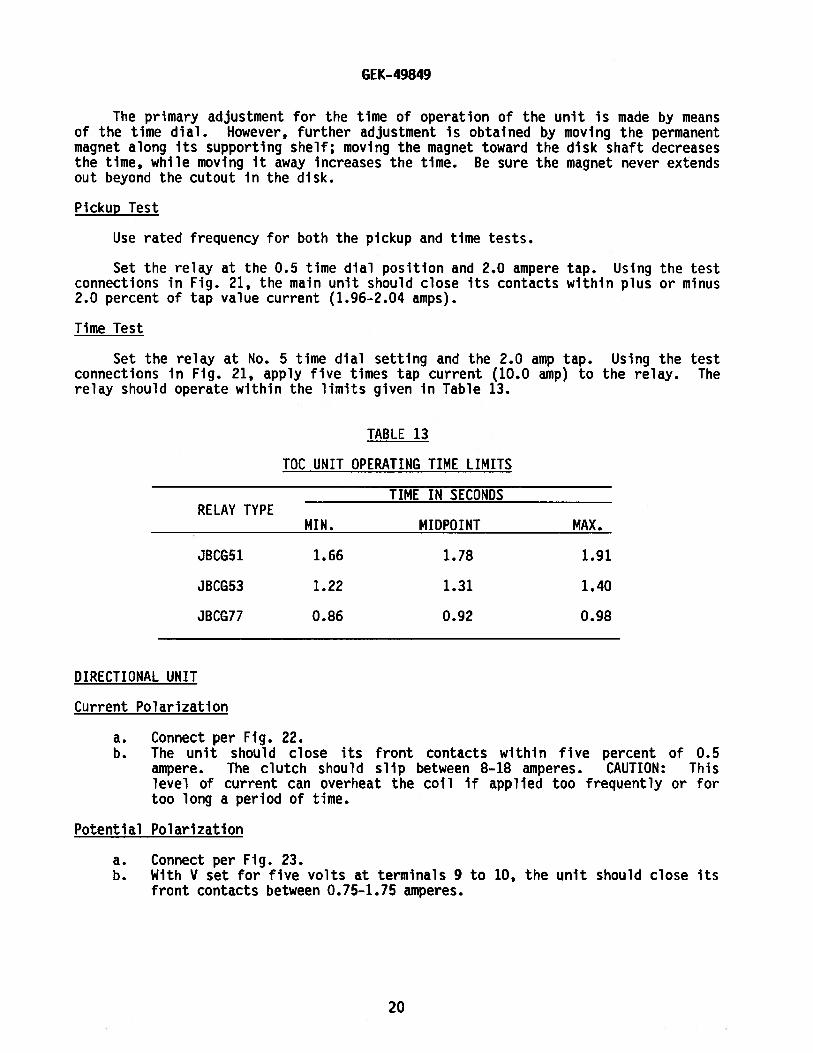
The primary adjustment for the time of operation of the unit is made by meansof the time dial. However, further adjustment is obtained by moving the permanentmagnet along its supporting shelf; moving the magnet toward the disk shaft decreasesthe time, while moving it away increases the time. Be sure the magnet never extendsout beyond the cutout In the disk.
Pickup Test
Use rated frequency for both the pickup and time tests.
Set the relay at the 0.5 time dial position and 2.0 ampere tap. Using the testconnections in Fig. 21, the main unit should close its contacts within plus or minus2.0 percent of tap value current (1.96-2.04 amps).
Time Test
Set the relay at No. 5 tIme dial setting and the 2.0 amp tap. Using the testconnections in Fig. 21, apply five times tap current (10.0 amp) to the relay. Therelay should operate within the limits given in Table 13.
TABLE 13
TOC UNIT OPERATING TIME LIMITS
TIME IN SECONDSRELAY TYPE
MIN. MIDPOINT MAX.
JBCG51 1.66 1.78 1.91
JBCG53 1.22 1.31 1.40
JBCG77 0.86 0.92 0.98
DIRECTIONAL UNIT
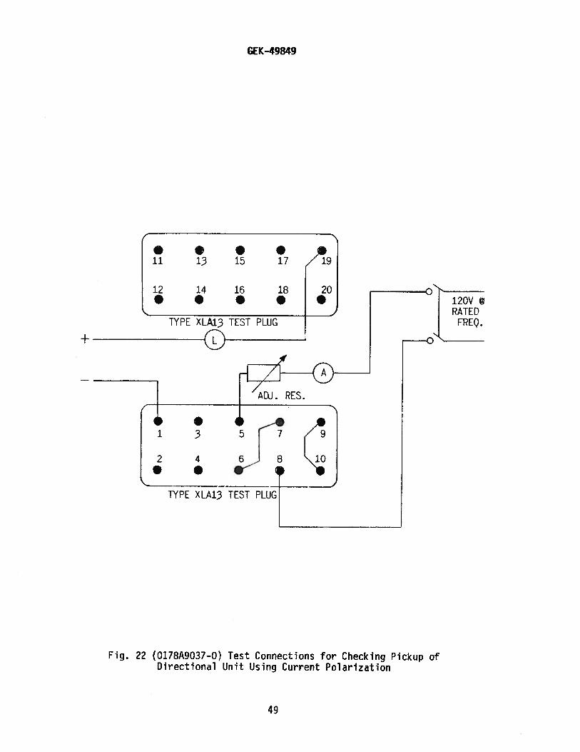
Current Polarization
a. Connect per Fig. 22.b. The unit should close its front contacts within five percent of 0.5
ampere. The clutch should slip between 8—18 amperes. CAUTION: Thislevel of current can overheat the coil if applied too frequently or fortoo long a period of time.
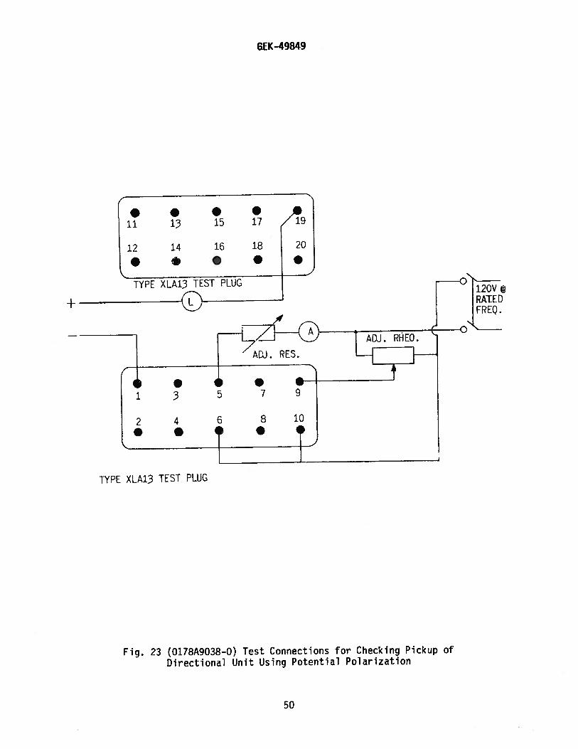
Potential Polarization
a. Connect per Fig. 23.b. With V set for five volts at terminals 9 to 10, the unit should close its
front contacts between 0.75—1.75 amperes.
20

GEK-49849
INSTANTANEOUS OVERCURRENT UNIT (DIRECTIONALLY CONTROLLED)
Pickup Setting
The pickup of the instantaneous overcurrent unit can be adjusted over aneight—to-one range, as indicated in Table 6, by varying the tension of the spiralcontrol spring and by selection of the appropriate series or parallel connections. Theoutside end of this spring is fastened to a post on the adjusting ring above the movingcontact, and the ring is in turn clamped in position by a hexagonal-head locking screw.If this screw is loosened, the ring can be slipped to vary the spring tension.
Make test connections as shown for the applicable relay type by Fig. 24. Inadjusting pickup, the desired pickup current should be passsed through the coils andthe control spring should be adjusted until the contact just closes. The adjustingring should then be locked in position and the pickup current rechecked. Note that thedirectional-unit contacts must be held closed during this adjustment.
INSTANTANEOUS UNIT (NON-DIRECTIONALLY CONTROLLED)
Make sure that the instantaneous unit is in the correct range in which it is tooperate. See the internal connections diagram and Table 7. Whenever possible, use thehigher range since the higher range has a higher continuous rating.
The instantaneous unit has an adjustable core located at the top of the unit. Toset the instantaneous unit to a desired pickup, loosen the locknut and adjust the core.Turning the core clockwise decreases the pickup, turning the core counterclockwiseincreases the pickup. Bring up the current slowly until the unit picks up. It may benecessary to repeat this operation, until the desired pickup value is obtained. Oncethe desired pickup value is reached, tighten the locknut.
CAUTION: Refer to Table 7 for the continuous and one second ratings of theinstantaneous unit. Do not exceed these ratings when applying current tothe instantaneous unit.
The range of the instantaneous unit (see Table 7) must be obtained between a coreposition of 1/8 of a turn of full clockwise, and 20 turns counterclockwise from thefull clockwise position.
INSTAllATIONLOCATION
The location should be clean and dry, free from dust and excessive vibration andwell lighted to facilitate inspection and testing.
MOUNTING
The relay should be mounted on a vertical surface. The outline and panel drillingdiagram is shown in Fig. 25.
21
GEK-49849
CONNECTIONS
The Internal connection diagrams for the various relays are shown In Fig. 5 to7.Typical wiring diagrams are shown by Fig. S and 9. Unless mounted on a steelpanel which adequately grounds the relay case, It Is recommended that the case begrounded through a mounting stud or screw with a conductor not less than #12 B&Sgage copper wire or Its equivalent.
INSPECTION
At the time of installation, the relay should be inspected for tarnishedcontacts, loose screws, or other imperfections. If any trouble is found, it shouldbe corrected in the manner described in the section on SERVICING.
CAUTION
Every circuit in the drawout case has an auxiliary brush. It is especiallyimportant on current circuits and other circuits with shorting bars that theauxiliary brush be bent high enough to engage the connecting plug or test plugbefore the main brushes do. This will prevent CT secondary circuits from beingopened. Refer to Fig. 20.
OPERAT ION
Before the relay is put Into service, It should be given a check to determinethat factory adjustments have not been disturbed. The time dial will be set at zerobefore the relay leaves the factory. If the setting has not been changed, it willbe necessary to change this setting in order to open the time overcurrent unitcontacts. The following tests are suggested:
TARGET AND SEAL-IN UNIT
1. Make sure that the tap screw is In the desired tap.2. Perform pickup and dropout tests as outlined in the ACCEPTANCE TESTS
section.
TIME OVERCURRENT UNIT
1. Set tap screw on desired tap. Using the test circuit In Fig. 21, applyapproximately twice tap value current until the contacts just close.Reduce the current until the light in series with the contacts begins toflicker. This value of current should be within five percent of tap value.
2. Check the operating time at some multiple of tap value. This multiple oftap value may be five times tap rating or the maximum fault current forwhich the relay must coordinate. The value used is left to the discretionof the user.
DIRECTIONAL UNIT
1. If current polarized or dual polarized, connect per Fig. 22.2. Adjust the control spring for 0.5 ampere pickup (front contacts)3. If potential polarized connect per Fig. 23.4. With voltage set at 5 volts at terminals 9 & 10, adjust the control spring
so that the unit closes its front contacts at 1.4 ±20% Amperes.
22
GEK-49849
INSTANTANEOUS OVERCURRENT UNIT (DIRECTIONALLY CONTROLLED)
Check pickup setting; see ACCEPTANCE TESTS.
INSTANTANEOUS UNIT (NON-DIRECTIONALLY CONTROLLED)
1. Select the desired range by making the proper connections at the rear of therelay (see internal connections diagram). Whenever possible always selectthe higher range since it has a higher continuous rating.
2. Set the instantaneous unit to pick up at the desired current level. See theACCEPTANCE TESTS section.
PERIODIC CHECKS AND ROUTINE MAINTENANCE
In view of the vital role of protective relays in the operation of a power system,it is important that a periodic test program be followed. It is recognized that theinterval between periodic checks will vary depending upon environment, type of relayand the user’s experience with periodic testing. Until the user has accumulated enoughexperience to select the test interval best suited to his individual requirements, itis suggested that the points listed below be checked at an interval of from one to twoyears.
These tests are intended to ensure that the relays have not deviated from theiroriginal settings. If deviations are encountered, the relay must be retested andserviced as described in this manual.
TARGET AND SEAL-IN UNIT
1. Check that the unit picks up at the values shown in Table 12.2. Check that the unit drops out at 25 percent or more of tap value.
TIME OVERCURRENT UNIT
1. Perform pickup test as described in the INSTALLATION section for the tap inservice.
2. Perform the time tests as described in the INSTALLATION section.
DIRECTIONAL UNIT
Repeat the portion of the installation test for the polarity condition for whichthe relay is connected in service.
INSTANTANEOUS OVERCURRENT UNIT (DIRECTIONALLY CONTROLLED)
Check that the instantaneous unit picks up at the desired current level, asoutlined in the ACCEPTANCE TESTS section.
23
GEK-49849
INSTANTANEOUS UNIT (NON—DIRECTIONALLY CONTROLLED)
Check that the instantaneous unit picks up at the desired current level, asoutlined in the ACCEPTANCE TESTS and the INSTALLATION TEST sections.
SERVICING
These relays are adjusted at the factory and it is advisable not to disturb theadjustments. If, for any reason, they have been disturbed or it is found duringinstallation or periodic testing that the relay is out of limits, the checks andadjustments outlined in the following paragraphs should be observed. It is suggestedthat this work be done in the laboratory.
TARGET AND SEAL-IN UNIT
Repeat the visual and mechanical inspections and the pickup and dropout currentchecks as outlined in the ACCEPTANCE TESTS section.
TIME OVERCURRENT UNIT
Disk and Bearings
The jewel should be turned up until the disk is centered in the air gaps, afterwhich it should be locked in this position by the set screw provided for this purpose.The upper bearing pin should next be adjusted so that the disk shaft has about 1/64 inchend play.
Contact Adjustment
The contacts should have about 1/32 inch wipe. That is, the stationary contacttip should be deflected about 1/32 inch when the disk completes its travel. Wipe isadjusted by turning the wipe adjustment screw thereby adjusting the position of thebrush relative to the brush stop.
When the time dial is moved to the position where it holds the contacts justclosed, it should indicate zero on the time—dial scale. If it does not and the brushesare correctly adjusted, shift the dial by changing the position of the arm attached tothe shaft just below the time dial. Loosen the screw clamping the arm to the shaft andturn the arm relative to the shaft until the contacts just make for zero time—dialsetting.
Characteristics Check and Adjustments
Repeat the portions of the ACCEPTANCE TESTS section that apply to the timeovercurrent unit. Also, check reset voltage and time as outlined under RESET in theCHARACTERISTICS section; low reset voltages or long reset times may indicate excessivefriction caused by a worn bearing or by mechanical interference.
On JBCG77 relays, set the relay on the two-amp tap with the time dial set so thatthe contacts are just open. Adjust pickup within the limits 1.96 to 2.04 amps, but asclose as possible to 2.0 amps. Then move the time dial to the No. 10 position and checkthe current required to just move the disk away from the stop arm. This current should
24
GEK—49849
be within the limits 1.88 to 2.12 amps. If the disk moves at the lower limit, checkthat movement is not over one-half inch, measured along the periphery of the disk.This is called a compensation check. If the current falls outside the 1.88 to 2.12 amplimits, the following steps should be taken: reset the control spring untilcompensation at No. 10 time dial is within limits. Then restore pickup by adjustingthe resistor. Recheck compensation after the resistor adjustment.
DIRECTIONAL UNIT
Bearings
The lower jewel bearing should be screwed all the way in until its head engagesthe end of the threaded core support. The upper bearing should be adjusted to allowabout 1/64 inch end play in the shaft.
To check the clearance between the iron core and the inside of the rotor cup,press down on the contact arm near the shaft, thus depressing the spring—mounted jeweluntil the cup strikes the iron. The shaft should move about 1/16 inch.
Cup and Stator
Should it be necessary to remove the cup—type rotor from the directional unit, thefollowing procedure should be followed:
All leads to the unit should first be disconnected and tagged for identificationin reconnecting. The unit can then be removed from the cradle with its mounting platestill attached.
The upper of the three flat-head screws holding the unit to the plate should nowbe removed. On some models, it may be necessary to remove a resistor or capacitor toexpose this screw. The four corner screws clamping the unit together, should next beremoved, and the entire top structure lifted off. This gives access to the cupassembly and exposes the stator assembly, which should be protected to keep it freefrom dust and metallic particles until the unit is reassembled.
To remove the shaft and rotor from the contact head assembly, the spring clip atthe top of the shaft must be pulled out and the clutch adjusting screw taken out of theside of the molded contact arm. The shaft and cup can now be pulled out of the molding.The rotor must be handled very carefully while it is out of the unit.
Contact Adjustments
To facilitate adjustment of contacts, remove the two red jumper leads fromterminals 18, 19 and 20 and use a neon indicating lamp iii series with an AC voltagesupply across terminals 18 and 19 and 19 and 20 to signify all contact closures. Referto Fig. 19 and Fig. 18 for identification of barrel and low gradient contact partsrespectively, arid proceed as follows:
Loosen slightly the screw which secures the barrel backstop (located at the rightfront corner of the unit) to its support. This screw should be only loose enough toallow the barrel to rotate in its sleeve but not so loose as to allow the sleeve to movewithin the support. Unwind the barrel backstop so that the moving contact arm ispermitted to swing freely. Adjust the tension of each low gradient contact brush so
25

GEK-49849
that one-to--two grains of pressure are required at the contact tip in order to cause theend of the brush to separate from the inner face of its respective brush retainer.Adjust the spiral spring until the moving contact arm is in a neutral position, i.e.,with the arm pointing directly forward. Loosen the locknut which secures thestationary contact mounting screw to the stationary contact support. Wind the mounting
screw inward until the low gradient stationary and moving contact members just begin totouch. Unwind the mounting screw until the stationary contact brush is vertical withthe stationary contact brush retainer down. Then tighten the locknut which secures themounting screw to the stationary contact support.
Loosen slightly the screw which secures the barrel contact to its support. Thisscrew should be only loose enough to allow the barrel to rotate in its sleeve, but notso loose as to allow the sleeve to move within the support. Wind the barrel backstop inuntil the low gradient moving and stationary contact members just begin to touch. Windthe barrel contact in until the barrel contacts just begin to touch. Unwind the barrelcontact one-quarter turn. Tighten the screw which secures the barrel contact to itssupport. Make sure that this screw is not so tight that it prevents the ball fromrolling freely within the barrel. Finally, adjust the tension on the low gradientstationary contact brush such that, when the contacts are made and fully wiped in,there is approximately an equal deflection on each brush.
CAUTION: When the above adjustments are complete, be sure to replace the two redjumper leads.
Bias Torque Ad,justment
Connect the current operating and current polarizing coils in series by connectinga jumper across terminals 6 and 7. Apply current to terminals 5 and 8 and adjust thedirectional unit spiral spring so that the unit picks up at 0.5 ampere.
The core of the directional unit has a small flat portion, the purpose of which isto minimize the effect of bias torques produced on the rotor. Such torques can beproduced by any one of the operating or polarizing quantities acting alone with theother two circuits de-energized. The adjustment of the core is made at the factory,but may be checked by observing that the unit responds as outlined below:
Short out the potential polarizing coil (terminals 9 and 10), leaving the currentpolarizing coil (terminals 7 and 8) unshorted. Supply thirty amperes through theoperating coil (terminals 5 and 6) and check that the unit does not operate.
If the unit does not satisfy the above conditions, rotate the core to a positionwhich causes it to do so. The core can be turned by loosening the large hexagonal nutat the bottom of the unit and turning the core by means of the slotted bearing screw.This screw should be held securely in position when the nut is retightened.
Keep n mind that thirty amperes will cause the current coils to overheat if lefton too long. Therefore, leave the test current on only for short intervals and allowsufficient time between tests for the coils to cool.
Clutch Adjustment
With the connections of Fig. 22, adjust the clutch to slip within the 10 to 15ampere limit. A screw, projecting from the side of the moving contact arm, controls
26
GEK-49849
the clutch pressure and, consequently, the current value which will cause the clutchto slip. Note that too frequent or too long application of these currents willoverheat the coils.
INSTANTANEOUS OVERCURRENT UNIT (DIRECTIONALLY CONTROLLED)
Bearings
The section BEARINGS, under DIRECTIONAL UNIT, also applies to the bearings ofthe instantaneous overcurrent unit.
Cup and Stator
The section CUP AND STATOR, under DIRECTIONAL UNIT, also applies to the cup andstator of the instantaneous overcurrent unit.
Contact Adjustments
The contact gap may be adjusted by loosening slightly the screw at the front ofthe contact support. The screw should be only loose enough to allow the contactbarrel to rotate in its sleeve.
The backstop screw fastened with a locknut should hold the moving contact armin a neutral position, i.e., with the arm pointing directly forward. Then byrotating the barrel, advance the stationary contact until it just touches the movingcontact. Next, back it away two and a half turns to obtain approximately 0.080 inchgap. Last, tighten the screw which secures the barrel.
The moving contact may he removed by loosening the screw which secures it tothe contact arm and sliding it from under the screw head.
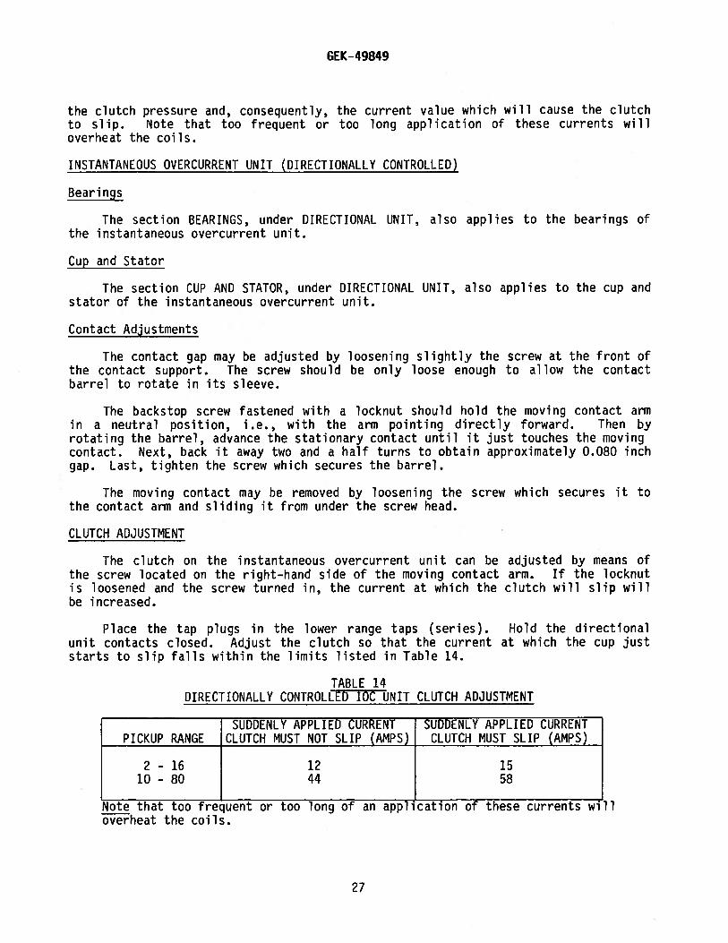
CLUTCH ADJUSTMENT
The clutch on the instantaneous overcurrent unit can be adjusted by means ofthe screw located on the right—hand side of the moving contact arm. If the locknutis loosened and the screw turned in, the current at which the clutch will slip willbe increased.
Place the tap plugs in the lower range taps (series). Hold the directionalunit contacts closed. Adjust the clutch so that the current at which the cup juststarts to slip falls within the limits listed in Table 14.
TABLE 14DIRECTIONALLY CONTROLLED IOC UNIT CLUTCH ADJUSTMENT
SUDDENLY APPLIED CURRENT SUDDENLY APPLIED CURRENTPICKUP RANGE CLUTCH MUST NOT SLIP (AMPS) CLUTCH MUST SLIP (AMPS)
2-16 12 1510-80 44 58
Note that too frequent or too long of an application of these currents willoverheat the coils.
27

GEK-49849
INSTANTANEOUS UNIT (NON—DIRECTIONALLY CONTROLLED)
1. Both contacts should close at the same time.
2. The backing strip should be so formed that the forked end (front) bearsagainst the molded strip under the armature.
3. WIth the armature against the pole piece, the cross member of the “T° springshould be in a horizontal plane and there should be at least 1/64 inch wipe onthe contacts. Check this by inserting a 0.010 inch feeler gage between thefront half of the shaded pole with the armature held closed. The contactsshould close with the feeler gage in place.
Contact Cleaning
For cleaning fine silver contacts, a flexible burnishing tool should be used. Thisconsists of a flexible strip of metal with an etched roughened surface, resembling ineffect a superfine file. The polishing action is so delicate that no scratches areleft, yet corroded material will be removed rapidly and thoroughly. The flexibility ofthe tool ensures the cleaning of the actual points of contact.
Fine silver contacts should not be cleaned with knives, files or abrasive paper orcloth. Knives or files may leave scratches which increase arcing and deterioration ofthe contacts. Abrasive paper or cloth may leave minute particles of insulating abrasivematerial in the contacts, thus preventing contact closing.
The burnishing tool described above can be obtained from the factory.
RENEWAL PARTS
It is recommended that sufficient quantities of renewal parts be carried in stockto enable the prompt replacement of any that are worn, broken or damaged.
When ordering renewal parts, address the nearest Sales Office of the GeneralElectric Company, specify quantity required, name of part wanted, and give completenameplate data. If possible, give the General Electric Company requisition number onwhich the relay was furnished. Refer to renewal parts publication GEF-4370.
Since the last edition, references to contacts have been clarified in the DirectionalUnit sections under ACCEPTANCE TESTS and OPERATION
28
GEK-49849
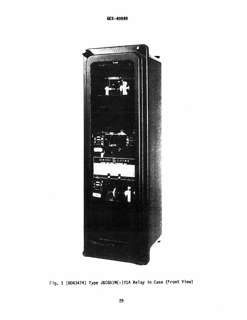
Fig. 1 (8043474) Type JBCG51M(-)Y1A Relay in Case (Front View)
2g

GEK-49849
Fig. 2 (8043475) Type JBCG51M(-)Y1A Relay Out of Case (Front View)
30
GEK-49849
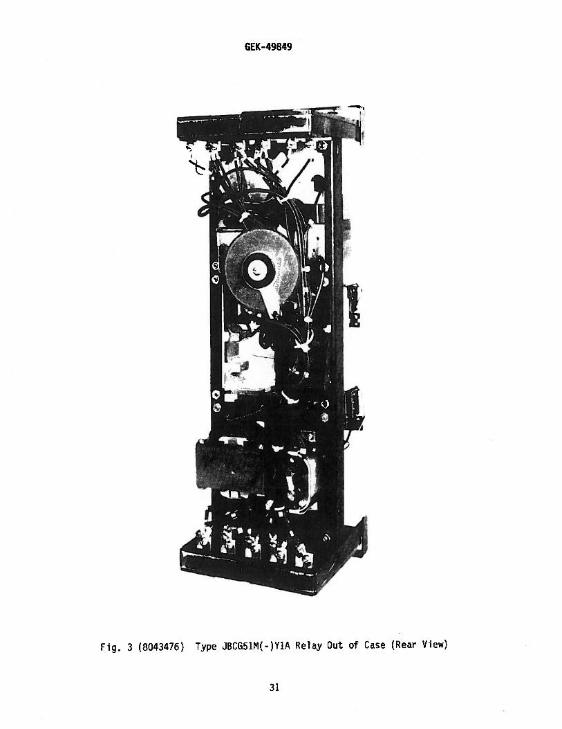
Fig. 3 (8043476) Type JBCG51M(-)Y1A Relay Out of Case (Rear View)
31

GEK-49849
“LATER1’
Fig. 4 ( ) Type JBCG77M Relay Out of Case (Rear View)
32

GEK—49849
IOC
DP0 T.POL.
2 4
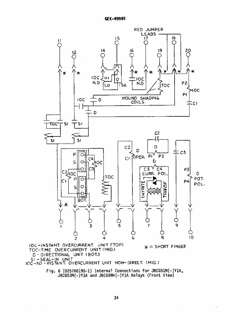
IOC-INSTANT. OVERCURENT UNIT (TOP)TOC-TIME OVERCURRENT UNIT (MID)
D - DIRECTIONAL UNIT (ROT.)SI -SEAL-IN UNIT
*=SHORT FINGER
Fig. 5 (0257A6195—O) Internal Connections for JBCG51M andJBCG53M Relays (Front View)
RED JUMPERLEAD S
C
/
18
OC
H
C2J>D
6 8 10
33
GEK-49849
RED JUMPER
2 4
bc -INSTANT. OVERCUPRENT JNIT (lOP)TOC-TIME OVERCURRENT UNIT(MID.)
0 - DIRECTIONAL UNIT (BOT.)SI -SEAL—IN UNIT
ICC—1’D -INSTANT OVERCURRENT UNIT NON—DIRECT: (MID.)
Fig. 6 (0257A6196-1) Internal Connections for JBCG51M(-)Y1A,JBCG53M(-)Y1A and JBCG99H(-)Y1A Relays (Front View)
bC
DPOT.POL.
I ‘4
2f*
ICC
H
C2
C2Qj
OPER PI P2D
= ShORT FINGER
34

GEK-49849
DPC T.POL.
CC —I NSTANT. Q\J EFCJRREW ‘NlT (TOP)T0C-TIE OVECURPENT UNIT (MID)
C -DIRECTIONAL UNIT (BOT,)SI -SEAL-IN UNIT
Fig. 7 (0257A6197-O) Internal Connections for JBCG77M Relay (Front View)
RED JUMPERLEADS —
20
TOCWOUND
S i—i AD IN GCOILS
ICC
H
-ICC
C2
C2’
ci OPER.C
TOC
II
SHORT FINGER
35

GEK-49849
LEGEND
ir POTENTIALPOLARIZATION IS USED,CONNECT A TO D &B TO C. IF POTENTIALPOLARIZATION IS NOTUSED, CONNECT C TO D
IF CURRENT POLARIZATIONIS NOT USED, DO NOT
CONNECT TO STUD 7&8.
— JBCG51 53 OR 77INSTANTANEOUS OVERCURRENT UNIT
— TIME OVERCURRENT UNITDIRECTIONAL UNIT
-- TARGET & SEAL—IN—UNIT.
867N
7t ;i
Fig. 8 (0148A4012-3) Typical External Connections Diagramfor Relay Types JBCG51M, JBCG53M or JBCG77M
12
3
PHASE SEQUENCE 1—2—3 OR 3 -2-4
I‘F I
0
H(--)w
0
(2
cì
ASLRELAYS
> D TOC IOC”I
L654
[52 13 21
(1)>-
-J\ W
—
Cl)—) <
A, 67N B
_____
C
K 10
TO TRANSFORMERNEUTRAL
I
67NCC
TOCD
T&SI
(+)
i52
52
f IC
C—)
36

0
6Th —
bcTOC —
0—T&sI —
LEGEND
GEK-49849
IF CURRENt PGLARIZATIONrs NOT USED. tX3 NOT
CONNECT TO STLU 7&8.
JBCG51 , 53 OR 77I NSTANTANEOUS OVERCURRENT (MITTIME OVERCURRENT UNIT 16DIRECTIONAL UNITTARGET SEAL—IN--UN!?. I
67NSI
123
PI.ASE SE1J DICE 1—2-3 &E
IF POTENTAL)LRIZATIO bi USED.
COlNECTA 10058 TO C. iF FOT1TT?ALFLARIZATfON IS1OTUSED, CL4LCT C TO D
ITO TRANSFOR€
NEUTRAL
81
7_
11
(4)
Fig. 9 (0273A9058—O) Typical External Connection Diagramfor Relay Types JBCG51M(-)Y1A and JBCG53M(-)Y1A
37
.4
‘so1.2
—‘- ‘ .8
z
— -CC) IX)
.4
cc
.2
0
1.4
GEK-49849
Fig. 10 (0362A0684—1) A Typical Comparison of Current, Potential or DualPolarization Showing Effect of Local Ground Tmpedance
of Directional Unit of Type LJBCG Relay
I I j ILIF POTENTIAL POLARIZED ——
- MULTIPLES OF PRODUCT PICK—UP
IF CURRENT POLARIZED
MULTIPLES OF PRODUCT PICK—UP
IF DUAL POLARIZED
MULTIPLES OF PRODUCT PICK UP
ANGLE BY WHICH 10 LAGS
ANGLE DY WhICH 10 LAbS I
POLARIZING VOLTAGE
POLARIZING CURRENTOPERATING CURRENT
EI0C05 (9—601 —
36 —101 CoS(
0.25
Fig. 11 (0367A0934-0) Time Characteristic of Dual PolarizedDirectional Unit of Type JBCG Relay
Ci CrS t IC’ 0 U) C’O Ci lEN r-t Its 0 C— ccl” 0 0 0 0 0 0 0 0 0 CH (‘1 rC )- Its -0 E— U) 0 Ci
0 0 0 0 0 0 0 0,4 H
LOCAL GROUND SOURCE INPEDENCE — SEC. OHMS
EEHF
—\--L
0
0I-)
r
I-
80
75
70
65
60
55
50
45
40
35
30
25
20
15
J0
S
0
1%
E1cos 1-9--6O1 II COS- p
3.6 0.25
EEEiH
— — r- = -.L
H its C- n-s & IXi -0 r— U) 05 0 XC Ci 0 C) C) 0 Cl C) 0 CiH 1 C4 in i- g’i ‘0 1— U) 0’ 0
C-’ HMULTIPLES OF PRODUCT PICKUP
0 C) 0 0 0 0 0 0 00ItS 0 0 0 0 0 0 0 00H Cd En & cc. -0 C- 10 0-0
1-1
38
GEK-49849
3 1.7111 2 3 4 3 410070
l’_IIIII I I 11111 1IIIl
400
000
$00
300
70000l0
70
ID
50
40
-. -4
ICP1
2
3,
0
a
.3
Fig. 12 (0888B0269-3) Time-current Characteristic of InverseTime Overcurrent Unit
400
100
200
1101
0. . C
2.02—I
20 30 40 30 10 10 I0I0
H WIFY1[ [IL. I-nil (IXIG 1FjF’
Ill IN II I
0.6.0.6,0.?,O.l,I,0,).2.I.,2U,2.2,3.0,4.0
l,’i,2.02.A, 3.0. .0,1.0,7.C.7,06.O. 0,127.0. 2. I, iA, A.U,’.fl.I .017.0,8.C. 0.0,7,6
INSI 1111
0. -4.0
2—Il
[0-So
20-Plo
.1 IIILLIIIII I I I I_I_iI LIII7I0
12
INSI 11111
(.ONTINIIOIP - II
All PU 21 01 LF
III
400
Jo’
To’IDIC
TO
— — —— 30
—-- 4--- -
— — — —— 40
——
0z073
zb2
p
\
20
II
-. 9-:8
4
. - — — - -
- c - — - -
In
C
VC,,
0
ci03
E
: : : E I : =
--Z— -h — — -- - -
— — —
— —I— — — — — — — -
. - -- — — —
IIa,
.02
.2
04
,H +iL. EtH t, EEEH Hn0 70 34 44 Ol07000l4
.04
03
.02
MULTIPLES OF RELAY TAP SETTING
g
39

GEK-49849
TIlIT TIll T
0.’,O.U,O./,T.li, 1.0, .2. 1.2.0,2.5, 3.0.40
I.5.2.0?.b,3,0.4.0.o.0.6.0,7.0.8.0.I0,12
2.0.2.S..l.0.6.0.5.0 6.0.7.O,U.0,I0.0,12, IT
1 0.1 iS I. IN IS
INSI. 13411
COH I NIJOUSLY
A UI U S IA AL L
01
z
N NI N NINIINZ
MULTIPLES OF RELAY TAP SETTING
I .7 .1 I 1 1 3 4 I I I I III
! HIt 111111—
‘I’’ 11111 I li NIT
— — — II N
‘II
I * I II!III I I I 111111
0. -‘I Ii
I. , I:.:)
— lb
1XTE’fF1 Pi1([ U3GO EflIF)
0. .-ll.fl
2-6IT—UT
20- 60
\\\
1*
E EEE EEE•.H
: .
4= EE.E: :EE::: :
— ._ .————__ .
,— —— \,‘‘: —— — -- ———- -- ——— ..-- 3
EE 7
‘0
1: ..EEEEE: :
‘:4
- 4
.t— — — —--
--—— —-- -.. ——-- j
..
. ---
at
-‘4
I:
I .1 .1 . .3 I I ii*ii I I IIIIIJ•
Fig. 13 (088880270-3) Time-current Characteristic of Very InverseTime Overcurrent Unit
40
GEK-49849
I .1.1.14 1 2 4 S 171151 20 30 40 53 10710110—
I I I I I I I I I I I
S II S
I III Oh I 5, IT
0. -4.0 (I. 5-..,-i:’.Q 2-i.
2—Is 0-0
20-Il P
TIll 11011 TAPS
I2.’,,0.’0.7O.R,l.O,I.7,I.,2.0.2.5,3.0,4.0
i. .0.2.S,3.0.ll.0,5.0S.0!.0.8.A. 0,2
70. 2.s. .0.0. .0.t .07.0,0,0, 10.0, 12. 5
A NJ U’ TO r N
ISITI liii -
COIl F INIOUSLYTAJIIS AOl.
.10 00 3 .0 50 44 120430 x
MULTIPLES OF RELAY TAP SETTING
Fig. 14 (0888130274—5) Time-current Characteristic of Extremely InverseTime Overcurrent Unit
300
400
200
203
I I I I I I I I I I I I I I I I_I I I LI I I I I I..[__..J I_i .1 IL .1 1 1 11 I I I I I
1>TE[’EL. p(,.fE (CCC 1F.IF.)
2l - —
OIl
IN
270
,30‘300
7’
-.-- -- - - — — —-- - .———--- I
“7
aCI.).0U,
a.0
\\
\\
\ \-- -
S —— — ————— — ——— ——
\
-1
aro,0
H liLT 111 -
zz-. \:‘\-:N
—--- -
: ‘-5’ : :
:1 I I
.11
! H!
41
z
GEK—49849
Fig. 15 (0285A6663) Representative Time—current Characteristic ofDirectionafly Controlled Instantaneous Overcurrent Unit
42
z::-z---
. . p_Ixxix
----,.---- -.. ...-- .-;
: cccr : :z lii LiJ
Lj ‘i ;
L 00— —
E
I ——
LL—
zz z:zz:C) ‘ ... :
— —
a——
F -
L1
Th-- --
cj I C) () I.-; C) i_•_ -. t
. iT jTI______ I I --_____

Om
1(0
0•
,i-
CDC
(1 —i.0
o0
0I
c-s.
.--
—S
o—
1__J
—
CO
rD C,
‘-4
z5
“-C
c-s.
CD c-s.
c-s.
ci,
(DO
.’0
—S c-s
.0(0
<-S
CD C,
c-s.
-4.
-sr,
-C CO
O -4-c
c-s.
c-s.
—I.
c-s.
0
I1S
EIi
ICRA
TED
INST
ANTA
NEOU
S1.R
IITOP
ERAT
ING
TIM
E
1.5
23
56
78
910
MU
LTIP
LES
OFP1

0 C
n•
C,
CD -1 II,.
C,
C -h CD
I C..)
uJ
cc
HIS
EI4
tCRA
TED
INST
ANTA
NEOU
SU
NIT
TRAN
SIEN
TOV
ERRE
A(}
02
08
A8
69
4
50AN
GLE
INC
EGEE
SLA
G

GEK-49849
0
E
0 - Moving Contact Arm
E - Moving Contact Brush
F — Button Contact Tip
G - t’loving Contact Brush Retainer
A - Contact Dial
B - Stationary Contact Brush
C — Conical Contact Tip
H — Brush Retainer
K - Stationary Contact Support
L - Mounting Screw
M — Locknuts
Fig. 18 (8023399 and 8027689) Low Gradient Contact Assembly forthe Directional Unit
/ --.--
K
A
H
45
GEK-49849
A- INCLINED TUBEB-STAINLESS STEEL BALLC- DIAPHRAM
C - CONTACT
D-SPACERE-CAPF-FLAT SPIRAL SPRING
Fig. 19 (K-6071069[ 4J) Barrel Contact Assembly for the Directionaland the Instantaneous Overcurrent Unit
A CD E
46

GEK-49849
CONNECTING PLUG MAIN BRUSH
NOTE: AFTER ENGAGING AUXILIARY BRUSH CONNECTING PLUG
TRAVELS 1/4 INCH BEFORE ENGAGING THE MAIN BRUSH ON
THE TERMINAL BLOCK
Fig. 20 (8025039) Cross-Section of Drawout Case Showing Positionof Auxiliary Brush
CONNECTING BLOCK
AUXILIARY BRUSH—ERMINAL BLO
SHORTING BAR
47
GEK-49849
7_ -
-. .11 13 15 17 19
12 14 16 18 20. . .
‘
Fig. 21 (0178A9036-0) Test Connections for Checking the TOG Unit
TYPE XLA13 TEST PLUG
TO TIMER‘STOP”
TO TIMERSTART”
48
GEK-49849
Fig. 22 (0178A9031-O) Test Connections for Checking Pickup ofDirectional Unit Using Current Polarization
+
TYPE XLA13 TEST PLUG
49
GEK-49849
1. . .11 13 15 17 /19
12 14 16 18 20
U’
Fig. 23 (0178A9038-O) Test Connections for Checking Pickup ofDirectional Unit Using Potential Polarization
TYPE XLA13 TEST PLUG
-1-
___________
1120V tIRATEDIFREQ.
TYPE XLA13 TEST PLUG
50

SEK-49849
TYPE XLA13 TEST PLUG
/1
I ADJ. RES.
. . .3 5 7 9
4 6 8 10• . •
TYPE XLA13 TEST PLUG
RELAY TYPE CONNECT
A B
JBCG 51 12 1953 12 19
77 12 19
52 13 19*
54 13 19*
78 13 j9*
*BLOCK DIRECT. UNITCONTACTS CLOSED
Fig. 24 (0178A9035-O) Test Connections for Checking Pickup ofDirectionally Controlled IOC Unit
•11
•13
•15
•17
12
•
•19
14
•16 18 20
•A 120VRATEDF REQ.
51

GEK-49849
Fig. 25 (K—6209276 15J) Outline and Panel Drilling Dimensions for JBCG Relays
PANEL LOCATION5/16-18 STUDSSURFACE MTG,
191715131100000
00000O 18 16 14 1
CUTOUTS MAY REPLACEDRILLED HOLES
PANEL DRILLINGSEMI-FLUSH MOUNTING
FRONT VIEW
TYPICAL DIM.INCHES
MM
PANEL DRILLINGFOR SURFACE MOUNTING
FRONT VIEW
VIEW SHOWING ASSEMBLY OF HARDWAREFOR SURFACE MTG. ON STEEL PANELS
52

GEK-49849
IOC=INSTANT. OVERCUPRENT UNIT (TOP)TOC=TIME OVERCURRENT UNIT ()4IDDLE)
D= DIR ECTI ONAL UNIT (BOTTOM)SI=SEAL—IN UNIT
- SHOPT FINGER
Fig. 26 (0273A9548-1) Internal Connections Diagram for the JBCG5211and the JBCG54M Relays
3
4 20
IOC
Ci
C2
OPEP, P1 P2D
C3
P3
P4
DPOT.P0 L.
2 4 x53

GEK—49849
‘cc
C’
DPOT.POL.
* — SHORT FiNGER
Fig. 27 (0273A9550 1J) Internal Connections Diagram for the JBCG78M(—)A Relay
2 4OC= INSTANT OVERCURREW UNIT (TOP)
TOC=T1MEOVERCURRENT UNIT(MIDDLE)DDIRECT)ONAL UNIT (BOTTCM)
SLSEAL-IN UNIT
S
54


GE Power Management
215 Anderson AvenueMarkham, OntarioCanada L6E 1B3Tel: (905) 294-6222Fax: (905) 201-2098www.ge.comlindsyslpm