gt 650 comet s r - owner's manual
TRANSCRIPT

1
This manual should be considered a permanent part of the motorcycle andshould remain with the motorcycle when resold or otherwise transferred toa new owner or operator. The manual contains important safety informa-tion and instructions which should be read carefully before operating themotorcycle.

22
(Standard type)

33
(Sports type)

4
All information, illustrations photographsand specifications contained in this manualare based on the latest product informationavailable at the time of publication. Due toimprovements or other changes, there maybe some discrepancies in this manual.Hyosung reserves the right to makechanges at any time.
Please note that this manual applies to allspecifications for all respective destinationsand explains all equipments. Therefore,your model may have different standardfeatures than shown in this manual.
HYOSUNG MOTORS & MACHINERY INC.
� COPYRIGHT HYOSUNG MOTORS & MACHINERY INC.
FOREWORD
THANK YOU for choosing Hyosungmotorcycle. We at Hyosung havedesigned, tested and produced thesemotorcycles using the most modern tech-nology available to provide you with muchhappy, enjoyable, safe riding. Motorcyclingis one of the most exhilarating sports andinsure you to enjoy riding and you shouldbecome thoroughly familiar with the infor-mation presented in this Owner's Manualbefore riding the motorcycle.
The proper care and maintenance thatyour motorcycle requires are outlined in thismanual.
By following these instructions explicitlyyou will insure a long trouble-free operatinglife for your motorcycle. Your Hyosungdealer has experienced technicians that aretrained to provide your machine with thebest possible service with the right tools andequipment.

5
IMPORTANT
BREAK-IN INFORMATION FOR YOUR MOTORCYCLE
The first 1,600km(1,000miles) are themost important in the life of your motorcycle.
Proper break-in operation during this timewill help ensure maximum life and perfor-mance from your new motorcycle.
Hyosung parts are manufactured of highquality materials, and manufactured partsare finished to close tolerances. Properbreak-in operation allows the machined sur-faces to polish each other and matesmoothly.
Motorcycle reliability and performancedepend on special care and restraint exer-cise during the break-in period. It is espe-cially important that you avoid operating theengine in a manner which could expose theengine parts to excessive heat.
Please refer to the BREAK-IN section forspecific break-in recommendations.
WARNING/CAUTION/NOTE
Please read this manual and follow itsinstructions carefully. To emphasize specialinformation the words 『 WARNING』,
『 CAUTION 』and 『 NOTE 』.
N O T EThis provides special information tomake maintenance easier or importantinstructions clearer.
These instructions point out special ser-vice procedures or precautions thatmust be followed to avoid damaging themachine.
CAUTION
The personal safety of the rider may beinvolved. Disregarding this information could result in injury to the rider.
WARNING

6
Noise Control System(muffler assembly)
TAMPERING WITH NOISE CONTROL SYSTEM PROHIBITED
Owners are warned that the law may prohibit :(a) The removal or rendering inoperative by any person other than for the
purpose of maintenance, repair or replacement, of any device or ele-ment of design incorporated into any new vehicle for the purpose ofnoise control prior to its any sale or delivery to the ultimate purchaser orwhile it is in use ; and
(b) The use of the vehicle after such device or element of design has beenremoved or rendered inoperative by any person.
MAINTENANCE:The exhaust system of this motorcycle requires no periodic maintenance.The engine should be adjusted to the manufacture’’s specifications and thespark plug should be kept in good condition. Running the engine withincorrectly operating spark plug or misadjusted carburetor may cause per-manent damage to the catalyst and to the noise control system.
WARNING

7
Motorcycle riding is great fun and an excit-ing sport. Motorcycle riding also requireshe/she to take some extra precautions toensure the safety of the rider and passen-ger. These precautions are:
●●Before first use of the read this owner’s manual carefully tob e c o m e f a m i l i a r w i t h t h e
’s features, and safe-ty and maintenance requirements.Review all instructions, requirementsand warnings with the riders. Keepthe owner’s manual in the owner’smanual storage compartment locatedunder the seat.
●●Before the rider’s first use of the, make sure that he
/ she is familiar with the location andoperation of all controls, and hasbeen instructed in the proper opera-tion of the motorcycle.
●● For first use of the ,find a level, open area for the rider touse to become familiar with the oper-ation of controls and the operatingand handling characteristics of the
.
WARNING
●● Before each use, perform dailyinspections with the rider. Specificitems to check are listed in theINSPECTION BEFORE RIDING sec-tion on page 56 of this owner’s man-ual.
●● Make sure the rider wears a helmet,eye protection, and protective cloth-ing (gloves, leather or heavy clothpants, long sleeved shirt or jacket,boots).
●● Permit use only by dual rider. Thesemotorcycles is designed for use onlyby dual rider.
●●Do not permit anyone to operate theunder the influence
of alcohol or other drugs caused bydamage to the motorcycle or alteredhandling characteristics.
●●Observe periodic maintenancerequirements your authorizedHYOSUNG dealer is trained andequipped to perform this service.
●●Drain gasoline from the fuel tank andcarburetor prior to transporting the
.●● Caution the rider and others near the
not to get close to ortouch any moving parts or any heat-ed areas such as the engine andexhaust system.
●● Do not make any modifications tothe . Modifications may make the motor-cycle unsafe or illegal in your state.
WARNINGCONSUMER INFORMATION
SAFE RIDING RECOMMENDATIONFOR MOTORCYCLE RIDERS
8
The is equipped with theside stand ignition interlock system.If the transmission is in neutral or sidestand up, you can only start the enginepulling the clutch lever.This side stand ignition interlock systemprevents the motorcycle from beingstarted with side stand down.Make sure that the side stand igintioninterlock system is working properlybefore riding.
WARNING
●●Do not run the engine indoors orwhere there is little or no ventilation.Exhaust gases contain carbonmonoxide, a potentially lethal gas thatis colorless and odorless.
●● Never leave the motorcycle runningwhile unattended, even for a shorttime.
WARNING
These motorcycles always come on thehead lamp, meter lamp and tail lampwhen starting engine.
CAUTION
While operating the , therider should keep both feet on thefootrests at all times, or injuries resultingfrom accidents. Moving the rider’s feetfrom the footrests reduces the rider’sability to control the motorcycle, andcould lead to an accident.
WARNING
Keep both hands on the handgrips at alltimes when riding. Removing yourhands from the handgrips reduces yourability to control the motorcycle, andcould result in an accident.
WARNING
Always open the throttle gradually toprevent front wheel lifting. Failure toobserve this precaution may result inloss of control and an accident.
WARNING
WHEN KEEPING FOR LONG PERIOD :1. Supply the enough fuel in the fuel
tank.2. Do drain wholly the fuel in the carbu-
retor.3. Remove the battery from the motorcy-
cle.
CAUTION
●●The trunk could be heated. Don’tkeep anything that doesn’t endureheat.
●●Don’t keep the fragile.●●Check if it is locked.●●The unlocking of rear seat could
cause serious accident.●●Don’t allow water to get inside the
trunk or it could damage.●●Don’t keep the valuables in the trunk
when leaving unattended.●●Loading limit of trunk : 1kkgg (2.21 lbs)
CAUTION
9
◉◉ WEAR A HELMET
◉◉ RIDING APPAREL
◉◉ INSPECTION BEFORE RIDING
◉◉ FAMILIARIZE YOURSELF WITHTHE MOTORCYCLE
◉◉ KNOW YOUR LIMITS
◉◉ BE EXTRA SAFETY CONSCIOUSON BAD WEATHER DAYS
Motorcycle safety equipment starts witha quality safety helmet. One of the mostserious injuries that can happen is ahead injury. ALWAYS wear a properlyapproved helmet. You should also weara suitable eye protection.
WARNING
Do not operate the ignition switch in the““OFF””or ““LOCK””position or theengine stop switch in the ““ ””positionwhile driving at one’s pleasure.
WARNING
Loose fancy clothing can be uncomfort-able and unsafe in terms of riding yourmotorcycle. Choose good quality motorcycle ridingapparel in terms of riding your motorcy-cle.
WARNING
Review thoroughly the instructions inthe ““INSPECTION BEFORE RIDING””section of this manual. Do not forget toperform an entire safety inspection toensure the safety of the rider and itspassenger.
WARNING
Your riding skill and mechanical knowl-edge from the foundation for safe ridingpractices.We suggest that you practice ridingyour motorcycle in a non-traffic situationuntil you are thoroughly familiar withyour machine and its controls.Remember practice makes perfect.
WARNING
Ride within the boundaries of your ownskill at all times. Knowing these limitsand staying within them will help you toavoid accidents.
WARNING
Riding on bad weather days, especiallywet ones, requires extra caution.Braking distances double on a rainyday. Stay off of the painted surfacemarks, manhole covers and greasyappearing areas as they can be espe-cially slippery. Use extreme caution at railway cross-ings and on metal gratings and bridges.Whenever you have a doubt about roadcondition, slow down!
WARNING

10
There are a great variety of accessoriesavailable to Hyosung owners. Hyosungcan not have direct control over the qualityor suitability of accessories you may wish topurchase except genuine parts.
The addition of unsuitable accessoriescan lead to unsafe operating conditions. Itis not possible for Hyosung to test eachaccessory on the market or combinationsof all the available accessories, however,your dealer can assist you in selecting qual-ity accessories and installing them correct-ly.
Use extreme caution when selecting andinstalling the accessories for yourHyosung. We have developed some gen-eral guidelines which will aid you whendeciding what kind of accessories you willselect and how to equip them into motorcy-cle.
1. In case that additional weight or aero-dynamic affecting accessories areinstalled, they should be mounted aslow as possible, as close to the motor-cycle and as near the center of gravityas is feasible. The mounting bracketsand other attachment hardware shouldbe carefully checked to ensure that itprovides for a rigid, nonmovablemount. Weak mounts can allow theshifting of the weight and create a dan-gerous, unstable condition.
2. Inspect for proper ground clearanceand bank angle. An improperly mount-ed load could critically reduce thesetwo safety factors. Also determine that
the “load”does not interfere with theoperation of the suspension, steeringor other control operations.
3. Accessories fitted to the handlebars orthe front fork area can create seriousstability problems. This extra weight willcause the motorcycle to be lessresponsive to your steering control.The weight may also cause oscillationsin the front end and lead to instabilityproblems. Accessories added to themachine should be as light as possibleand kept to a minimum.
4. The motorcycle may be affected by alifting condition or by an instability incross winds or when being passed orpassing large vehicles. Improperlymounted or poorly designed acces-sories can result in an unsafe ridingcondition, therefore caution should beused when selecting and installing allaccessories.
5. Certain accessories displace the riderfrom his or her normal riding position.This limits the freedom of movement ofthe rider and may limit his or her controlability.
6. Additional electrical accessories maydamage the existing electrical system.Severe overloads may damage thewiring harness or create a dangeroussituation due to the loss of electricalpower during the operation of themotorcycle.
When carrying a load on the motorcycle,mount it as low as possible and as close aspossible to the machine. An improperlymounted load can create a high center ofgravity which is very dangerous and makesthe motorcycle difficult to handle. The sizeof the “load”can also affect the aerody-namics and handling of the motorcycle.
ACCESSORY INSTALLATION ANDPRECAUTION SAFETY TIPS

11
Modification of the motorcycle, orremoval of original equipment may ren-der the vehicle unsafe or illegal.
WARNING
Balance the load between the left andright side of the motorcycle and fasten itsecurely.

12
1. SERIAL NUMBER LOCATION ∙∙∙∙∙∙∙∙∙∙∙∙∙∙∙∙ 14
2. FUEL , ENGINE OIL AND COOLANT RECOMMENDATION∙∙ 14FUEL ENGINE OILCOOLANT
3. NAMES OF EACH PARTS [ ]∙∙∙∙∙∙∙∙∙∙∙ 174. NAMES OF EACH PARTS [ (Standard type)] ∙∙∙ 205. NAMES OF EACH PARTS [ (Sports type)] ∙∙∙∙ 236. NAMES OF EACH PARTS [ ] ∙∙∙∙∙∙∙∙∙ 26
7. CONTROLS ∙∙∙∙∙∙∙∙∙∙∙∙∙∙∙∙∙∙∙∙∙∙∙∙∙ 29IGNITION SWITCH IGNITION KEYINSTRUMENT PANEL( )INSTRUMENT PANEL( & )LEFT HANDLE SWITCHRIGHT HANDLE SWITCHCARBURETOR CHOKE LEVERREAR BRAKE PEDALGEARSHIFT LEVERFOOTRESTSSIDE STANDSEAT LOCKTRUNKREAR SHOCK ABSORBERFRONT FORK
8. SUPPLY OF GASOLINE , ENGINE OIL AND COOLANT ∙∙∙ 44GASOLINEENGINE OILCOOLANT
9. RIDING TIPS ∙∙∙∙∙∙∙∙∙∙∙∙∙∙∙∙∙∙∙∙∙∙∙∙∙50STARTING THE ENGINESTARTING OFF
TABLE OF CONTENTS

13
USING THE TRANSMISSIONRIDING ON HILLSSTOPPING AND PARKING
10. BREAK-IN ∙∙∙∙∙∙∙∙∙∙∙∙∙∙∙∙∙∙∙∙∙∙∙∙∙ 54
11. INSPECTION BEFORE RIDING ∙∙∙∙∙∙∙∙∙∙∙∙∙∙∙56
12. PERIODIC MAINTENANCE ∙∙∙∙∙∙∙∙∙∙∙∙∙∙∙∙∙ 57
13. INSPECTION AND MAINTENANCE ∙∙∙∙∙∙∙∙∙∙∙∙∙60TOOLFUEL HOSEENGINE OILGASOLINECOOLANTRADIATORRADIATOR HOSERUBBER CAP OF CABLESEXHAUST PIPE AND MUFFLERFRONT FORKREAR SHOCK ABSORBERBATTERYAIR CLEANERSPARK PLUGCARBURETORCLUTCH ADJUSTMENTDRIVE CHAINBRAKESTIREREPLACEMENT OF THE LAMPWHEN THE ENGINE REFUSES TO STARTWHEN KEEPING FOR LONG PERIODCLEANING PROCEDURE
14. LABEL ∙∙∙∙∙∙∙∙∙∙∙∙∙∙∙∙∙∙∙∙∙∙∙∙∙∙∙81
15. SPECIFICATIONS ∙∙∙∙∙∙∙∙∙∙∙∙∙∙∙∙∙∙∙∙∙∙83

14
F U E L
Frame number :
Engine number :
The frame number ① is stamped on thesteering head tube.
The engine serial number ② is stampedon the left downside of the crankcaseassembly.
Please write down the numbers in the boxprovided below for your future reference.
The frame and/or engine serial numbersare used to register the motorcycle. Theyare also to assist your dealer in terms ofordering parts or referring to special ser-vice information.
Use unleaded gasoline with an octanerating of 91 or higher.
Unleaded gasoline can extend spark pluglife and exhaust components life.
SERIAL NUMBER LOCATION
FUEL, ENGINE OIL ANDCOOLANT RECOMMENDATION
●● When refueling, always shut theengine off and turn the ignition keyto the ““OFF””position. Never refuelnear the flames, sparks and heatsources.
●● Do not overfill the fuel tank. Do not fillthe fuel tank above the entrancelower end.
WARNING
Spilling gasoline can damage the paint-ed surfaces.Be careful not to spill any fuel when fill-ing the fuel tank.Wipe spilled gasoline up immediately.
CAUTION
�
�

15
ENGINE OIL COOLANT
Classification system
API
SAE
Grade
Over SG
10W/40
Remarks
◉◉ ENGINE OIL SPECIFICATION
ENGINE OIL
Temperature ℃
℉
-30
-22
-20
-4
-10
14
0
32
10
50
20
68
30
86
40
104
20W50
15W40 15W50
10W40 10W50
10W30
Using a premium quality four stroke motoroil will increase the service life of yourmotorcycle.
Use an anti-freeze compatible with alu-minium radiator mixed with distilled wateronly at the ratio of 50:50
※ If a SAE 10W/40 motor oil is not avail-able, select alternative according to thefollowing chart.
●● Don’’t mix the unrecommended oil. Itcould damage the engine.
●● When refilling the oil, don’’t allow thedust to get inside.
●● Mop the oil spilt.●● Don’’t put the patch on the filler cap.
It could disturb the oil to be providedand damage the engine.
WARNING
Engine coolant is harmful or fatal ifswallowed or inhaled.
Do not drink anti-freeze or coolant solu-tion. If swallowed, do induce vomiting.Immediately contact a poison controlcenter or a physician. Avoid inhalingmist or hot vapors ; if inhaled, remove tofresh air. If coolant gets in eyes, flusheyes with water and seek medical atten-tion. Wash thoroughly after handling.Solution can be poisonous to animals.Keep out of the reach of children andanimals.
WARNING
Spilled engine coolant can damagepainted surfaces.
Do not spill any fluid when filling theradiator. Wipe spilled engine coolantup immediately.
CAUTION
◉◉ WATER FOR MIXINGUse distilled water only. Water other thandistilled water can corrode and clog the alu-minium radiator.

16
N O T EThis 50%%mixture will protect the coolingsystem from freezing at temperaturesabove -31℃℃. If the motorcycle is to beexposed to temperature below -31℃℃,,
this mixing ratio should be increased upto 55%% (-40℃℃) or 60%% (-55℃℃). The mix-ing ratio should not exceed 60%%.
◉◉ ANTI-FREEZEThe coolant performs as rust inhibitor andwater pump lubricant as well as anti-freeze.Therefore the coolant should be used at alltimes even though the atmospheric temper-ature in your area does not go down tofreezing point.
50%Water
Coolant
0.8ℓ
0.8ℓ
Required amount of water/coolant
Solution capacity(total) 1.6ℓ
◉◉ COOLANT RESERVOIR TANK☞ Refer to 48 page.

17
NAMES OF EACH PARTS [ ]
① Clutch lever② Left handle switches③ Choke lever④ Speedometer⑤ Coolant temperature meter⑥ Tachometer
⑦ Front brake fluid reservoir⑧ Right handle switches⑨ Front brake lever⑩ Throttle grip⑪ Ignition switches⑫ Fuel tank cap

18
⑬ Spark pulg (Front)⑭ Head lamp⑮ Front turn signal lamp� Ignition coil (Front)� Ignition coil (Rear)� Spark pulg (Rear)� Fuses� Seat lock
� Rear turn signal lamp� Tail/Brake lamp� License plate lamp� Passenger footrests� Footrests� Gearshift lever� Side stand� Engine oil drain plug
N O T E““ ””:: means the invisable parts.
�
�
�
�
� �
� �� �
�
� ��
�
�

19
� Muffler� Rear seat & Trunk
Front seatToolsBatteryFuel pumpThrottle stop screwAir cleanerFront brake fluid reservoirFront brake lamp switch
RadiatorCooling fan and motorEngine oil filterEngine oil filler capWater pumpEngine oil level lensRear brake pedalRear brake lamp switchCoolant reserve tankRear brake fluid reservoir
N O T E““ ””:: means the invisable parts.
�
�

20
NAMES OF EACH PARTS [ (Standard type)]
① Clutch lever② Left handle switches③ Choke lever④ Tachometer⑤ Speedometer⑥ Front brake fluid reservoir
⑦ Right handle switches⑧ Front brake lever⑨ Throttle grip⑩ Ignition switches⑪ Fuel tank cap
���
� ��
�
�
��
�
(Standard type)

21
⑫ Spark pulg (Front)⑬ Front turn signal lamp⑭ Head lamp⑮ Ignition coil (Front)� Ignition coil (Rear)� Spark pulg (Rear)� Fuses� Seat lock
� Rear turn signal lamp� Tail/Brake lamp� License plate lamp� Passenger footrests� Footrests� Gearshift lever� Side stand� Engine oil drain plug
N O T E““ ””:: means the invisable parts.
��
�
�
�
� �
� � � �
�
�
�
�
�(Standard type)

22
� Muffler� Rear carrier� Rear seat & Trunk
Front seatToolsBatteryFuel pumpThrottle stop screwAir cleanerFront brake fluid reservoirFront brake lamp switch
Side cowling innerRadiatorCooling fan and motorEngine oil filterWater pumpEngine oil level lensEngine oil filler capRear brake pedalRear brake lamp switchCoolant reserve tankRear brake fluid reservoir
(Standard type)
N O T E““ ””:: means the invisable parts.

23
NAMES OF EACH PARTS [ (Sports type)]
① Clutch lever② Left handle switches③ Choke lever④ Tachometer⑤ Speedometer⑥ Front brake fluid reservoir
⑦ Right handle switches⑧ Front brake lever⑨ Throttle grip⑩ Ignition switches⑪ Fuel tank cap
���
�
�
�
�
�
�
�
�
(Sports type)

24
⑫ Spark pulg (Front)⑬ Front turn signal lamp⑭ Head lamp⑮ Ignition coil (Front)� Ignition coil (Rear)� Spark pulg (Rear)� Fuses� Seat lock
� Rear turn signal lamp� Tail/Brake lamp� License plate lamp� Passenger footrests� Footrests� Gearshift lever� Side stand� Engine oil drain plug
N O T E““ ””:: means the invisable parts.
(Sports type)

25
N O T E““ ””:: means the invisable parts.
� Muffler� Rear carrier� Rear seat & Trunk
Front seatToolsBatteryFuel pumpThrottle stop screwAir cleanerFront brake fluid reservoirFront brake lamp switch
Side cowling innerRadiatorCooling fan and motorEngine oil filterWater pumpEngine oil level lensEngine oil filler capRear brake pedalRear brake lamp switchCoolant reserve tankRear brake fluid reservoir
(Sports type)

26
NAMES OF EACH PARTS [ ]
① Clutch lever② Left handle switches③ Choke lever④ Tachometer⑤ Speedometer⑥ Front brake fluid reservoir
⑦ Right handle switches⑧ Front brake lever⑨ Throttle grip⑩ Ignition switches⑪ Fuel tank cap

27
⑫ Spark pulg (Front)⑬ Front turn signal lamp⑭ Head lamp⑮ Ignition coil (Front)� Ignition coil (Rear)� Spark pulg (Rear)� Fuses� Seat lock
� Rear turn signal lamp� Tail/Brake lamp� License plate lamp� Passenger footrests� Footrests� Gearshift lever� Side stand� Engine oil drain plug
N O T E““ ””:: means the invisable parts.

28
� Muffler� Rear carrier� Rear seat & Trunk
Front seatToolsBatteryFuel pumpThrottle stop screwAir cleanerFront brake fluid reservoirFront brake lamp switch
Side cowling innerRadiatorCooling fan and motorEngine oil filterWater pumpEngine oil level lensEngine oil filler capRear brake pedalRear brake lamp switchCoolant reserve tankRear brake fluid reservoir
N O T E““ ””:: means the invisable parts.
29
KEY
KEYSTEERINGLOCK
Key number :
comes equipped with apair of identical ignition keys. Keep thespare key in a safe place.
Your motorcycle ignition keys arestamped with an identifying number. Thisnumber is used when making replacementkeys. Please write your key number in thebox provided for your future reference.
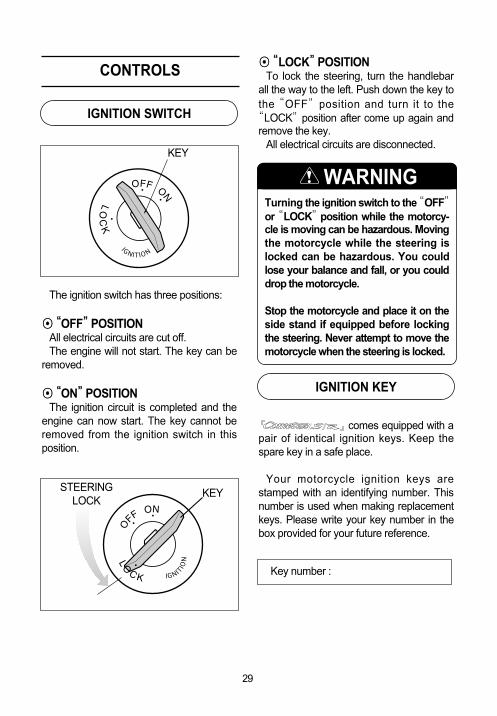
The ignition switch has three positions:
◉◉““OFF””POSITIONAll electrical circuits are cut off.The engine will not start. The key can be
removed.
◉◉““ON””POSITIONThe ignition circuit is completed and the
engine can now start. The key cannot beremoved from the ignition switch in thisposition.
CONTROLS
IGNITION SWITCH
IGNITION KEY
Turning the ignition switch to the “OFF”
or “LOCK”position while the motorcy-cle is moving can be hazardous. Movingthe motorcycle while the steering islocked can be hazardous. You couldlose your balance and fall, or you coulddrop the motorcycle.
Stop the motorcycle and place it on theside stand if equipped before lockingthe steering. Never attempt to move themotorcycle when the steering is locked.
WARNING
◉◉““LOCK””POSITIONTo lock the steering, turn the handlebar
all the way to the left. Push down the key tothe “OFF”position and turn it to the
“LOCK”position after come up again andremove the key.
All electrical circuits are disconnected.
30
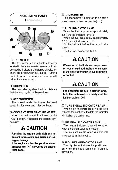
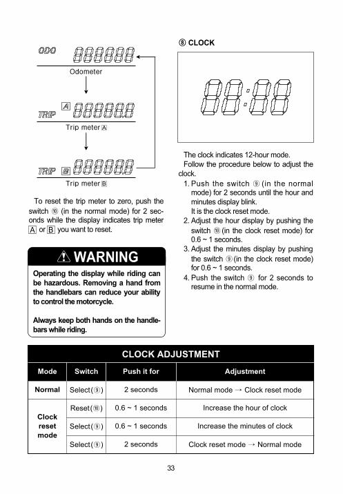
① TRIP METERThe trip meter is a resettable odometer
located in the speedometer assembly. It canbe used to indicate the distance traveled onshort trip or between fuel stops. Turningcontrol button ② counter-clockwise willreturn the meter to zero.
③③ ODOMETERThe odometer registers the total distance
that the motorcycle has been ridden.
④④ SPEEDOMETERThe speedometer indicates the road
speed in kilometers and miles per hour.
⑤⑤ COOLANT TEMPERATURE METERWhen the ignition switch is turned to the
“ON”position, it indicates the coolant tem-perature.
INSTRUMENT PANEL( )
When the fuel indicator lamp comeson, you should add fuel to the fuel tankat the first opportunity to avoid runningout of fuel.
CAUTION
⑥⑥ TACHOMETERThe tachometer indicates the engine
speed in revolutions per minutes(rpm).
⑦⑦ FUEL INDICATOR LAMPWhen the fuel drop below approximately
8.5ℓ, the indicator lamp lit.When the fuel drop below approximately
3.0ℓ, the indicator lamp lit.Fill the fuel tank before the indicator
lamp lit.The fuel tank capacity is 17.0ℓ.
⑧⑧ TURN SIGNAL INDICATOR LAMPWhen the turn signals are being operated
either to the right or to the left, the indicatorwill flash at the same time.
⑨⑨ NEUTRAL INDICATOR LAMPThe neutral indicator lamp will come on
when the transmission is in neutral.The lamp will go out when you shift into
any gear other than neutral.
⑩⑩ HIGH BEAM INDICATOR LAMPThe high beam indicator lamp will come
on when the head lamp high beam isturned on.
For checking the fuel indicator lamp,hold the motorcycle vertically and theignition switch “ON”.
CAUTION
Running the engine with high enginecoolant temperature can cause seriousengine damage.If the engine coolant temperature meterindicates the “H”mark, stop the engineto let it cool.
CAUTION
�
�
� � ��
��
�
��

③③ HIGH BEAM INDICATOR LAMPThe high beam indicator lamp will come
on when the head lamp high beam isturned on.
④④ NEUTRAL INDICATOR LAMPThe neutral indicator lamp will come on
when the transmission is in neutral.The lamp will go out when you shift into
any gear other than neutral.
⑤⑤ COOLANT TEMPERATURE METER
① TACHOMETERThe tachometer indicates the engine
speed in revolutions per minutes(rpm).
②② TURN SIGNAL INDICATOR LAMPWhen the turn signals are being operated
either to the right or to the left, the indicatorwill flash at the same time.
INSTRUMENT PANEL( & )
Running the engine with high enginecoolant temperature can cause seriousengine damage.If the engine coolant temperature metercomes on the red lamp of “H”mark,stop the engine to let it cool.
CAUTION
When the ignition switch is turned to the“ON” position, the display of speedome-ter will come on.
CAUTION
To adjust the light of speedometer dis-play, push the switch ⑨⑨ (in the normalmode) for 0.6 ~ 1 seconds while youwant to change.
[Light of speedometer display]100%
↓↓75%↓↓
50%↓↓
25%
CAUTION
31
『 』& 『 』’s thespeedometer is VFD(Vacuum FluorescentDisplay) type, it indicates the coolant tem-perature.
The “H”(Hot) mark indicates the coolanttemperature is hot.
When the coolant temperature is higherthan 125℃, the red lamp of “H”(Hot) markcomes on.
The “C”(Cool) mark indicates the coolanttemperature is cool.

32
⑥ FUEL METER
When the red lamp of “E” mark comeson only, you should add fuel to the fueltank at the first opportunity to avoid run-ning out of fuel.
CAUTION
For checking the fuel meter, hold themotorcycle vertically and the ignitionswitch “ON”.
CAUTION
⑦⑦ ODOMETER / TRIP METERThe display in it has three functions,
odometer and two trip meters.The display changes odometer or trip
meter, as indicated before turning the igni-tion switch off.
The odometer registers the total distancethat the motorcycle has been ridden.
The two trip meters are resettableodometer.
They can register two kinds of distance atthe same time. For instance, trip meter Acan register the trip distance and trip meter� can register the distance between fuelstops.
To change the display, push the switch⑩ (in the normal mode) for 0.6 ~ 1 secondswhile the display indicates the odometer,trip meter � or trip meter � you want tochange.
A
B
A B
『 』& 『 』’s thespeedometer is VFD(Vacuum FluorescentDisplay) type, it indicates the remaining fuelamount in the fuel tank.
The “F”(Full) mark indicates the fuel tankis full.
The “E”(Empty) mark indicates the fueltank is empty or nearly so.
When the remaining fuel is approximately3.4ℓ, the red lamp of “E”(Empty) markcomes on only.
Fill the fuel tank before the red lamp of“E”(Empty) mark came on only.
The fuel tank capacity is 17.0ℓ.
33
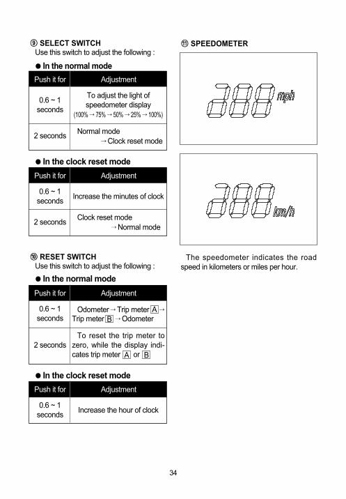
⑧⑧ CLOCK
The clock indicates 12-hour mode.Follow the procedure below to adjust the
clock.1. Push the switch ⑨ (in the normal
mode) for 2 seconds until the hour andminutes display blink.
1. It is the clock reset mode.2. Adjust the hour display by pushing the
switch ⑩ (in the clock reset mode) for0.6 ~ 1 seconds.
3. Adjust the minutes display by pushingthe switch ⑨ (in the clock reset mode)for 0.6 ~ 1 seconds.
4. Push the switch ⑨ for 2 seconds toresume in the normal mode.
To reset the trip meter to zero, push theswitch ⑩ (in the normal mode) for 2 sec-onds while the display indicates trip meterB or B you want to reset.A B
Operating the display while riding canbe hazardous. Removing a hand fromthe handlebars can reduce your abilityto control the motorcycle.
Always keep both hands on the handle-bars while riding.
WARNING
Normal
Clockresetmode
Mode
Select (⑨)
Reset(⑩)
Select (⑨)
Select (⑨)
2 seconds
0.6 ~ 1 seconds
0.6 ~ 1 seconds
2 seconds
Normal mode → Clock reset mode
Increase the hour of clock
Increase the minutes of clock
Clock reset mode → Normal mode
Switch Push it for Adjustment
CLOCK ADJUSTMENT
34
⑨⑨ SELECT SWITCHUse this switch to adjust the following :
● In the normal mode
Push it for
0.6 ~ 1 seconds
Adjustment
To adjust the light of speedometer display
(100% → 75% → 50% → 25% → 100%)
2 seconds Normal mode→ Clock reset mode
● In the clock reset mode
Push it for
0.6 ~ 1 seconds
Adjustment
Increase the minutes of clock
2 secondsClock reset mode
→ Normal mode
⑩⑩ RESET SWITCHUse this switch to adjust the following :
● In the normal mode
Push it for
2 seconds
Adjustment
To reset the trip meter tozero, while the display indi-cates trip meter or
0.6 ~ 1 seconds
Odometer → Trip meter →Trip meter → Odometer
● In the clock reset mode
Push it for
0.6 ~ 1 seconds
Adjustment
Increase the hour of clock
AB
A B
⑪⑪ SPEEDOMETER
The speedometer indicates the roadspeed in kilometers or miles per hour.

35
①① CLUTCH LEVERThe clutch lever is used for disengaging
the drive to the rear wheel when startingthe engine or shifting the transmission gear.
Squeezing the lever disengages theclutch.
②②““PASS ””SWITCHPress the “PASS”switch to operate the
head lamp high beam for using when pass.With the ignition switch in the “ON”posi-
tion, push the “PASS”switch to operatethe head lamp high beam.
⑤⑤ HORN SWITCHPress the switch to operate the horn.
④④ TURN SIGNAL SWITCHUsing when left, right turn or change
direction.
◉“ � ”Position : Flash the left turn sig-nal lamp.
◉“ � ”Position : Flash the right turnsignal lamp.
③③ DIMMER SWITCHChange the direction of head lamp light.
◉“ ”: The head lamp high beamcome on.The high beam indicator lampalso comes on.
◉“ ”: The head lamp low beamcome on.
LEFT HANDLE SWITCH
Do not operate when the dimmer switch““ ””position.
CAUTION
Set the dimmer switch ““ ””when othervehicle is running in front or against.
WARNING
Always use the turn signals when youintend to change lanes or make a turn.Always be sure to turn the turn signalswitch to the ““OFF””position after com-pleting the turn or lane change.
CAUTION
��
� � �

36
④④ HAZARD WARNING SWITCH◉“ ”: All four turn signal lamp and
indicator lamp will flash simul-taneously when the switch isturn on with the ignition switchin “ON”position.
◉“ ”: The turn signal lamp and indi-cator lamp go off.
Use the hazard warning lamps to warnother traffic during emergency parking orwhen your vehicle could otherwise becomea traffic hazard.
⑤⑤ STARTER SWITCHUse this switch to operate the starting
motor. With the ignition switch in the “ON”posi-
tion, the engine stop switch in the “ ”position, and the transmission is in neutral,pull in the clutch lever and side stand upand push the starter switch to start theengine.
③③ THROTTLE GRIPEngine speed is controlled by position of
the throttle grip. Turn it toward you toincrease engine speed. Turn it away fromyou to decrease the engine speed.
Apply the brake lightly and with greatcare on slippery surfaces to avoid skid-ding.
WARNING
Avoid turning the throttle grip duringbrakes.
WARNING
Do not operate for the engine stopswitch is in the ““ ””position while dri-ving at one’’s pleasure.
①① ENGINE STOP SWITCH◉“ ”Position : Using when dangerous
condition of falling down duringdrive and others or engine stopsuddenly. The ignition circuit isoff. The engine cannot start orrun.
◉“ ”Position : Using when needoperation of engine as drive andothers. The ignition circuit is onand the engine can run.
RIGHT HANDLE SWITCH
②② FRONT BRAKE LEVERThe front brake is applied by squeezing
the brake lever gently toward the throttle-grip.
Front brake be anxious about motorcyclefalling down when braking suddenly as diskbrake system. The brake lamp will come onwhen the lever is squeezed.
WARNING
� �
���

37
The carburetor is equipped with a chokesystem to provide easy starting when theengine is cold.
When starting the cold engine, turn thechoke lever all the way toward you. Thechoke works best when the throttle is in theclosed position. When the engine warm,you do not need to use the choke systemfor starting.
Do not engage the starting motor formore than five seconds at a time as itmay overheat the wiring harness andstarting motor.If the engine does not start after severalattempts, check the fuel supply and igin-tion system.(Refer to Page 78)
CAUTION CARBURETOR CHOKE LEVER
If you keep running in condition of fullchoke lever, causes fuel excess exhaus-tion, high speed not to run, it may dam-age ignition plug.
CAUTION
The is equipped withthe side stand ignition interlock system.If the transmission is in neutral or sidestand up, you can only start the enginewith pulling in the clutch lever.This side stand ignition interlock systemprevents the motorcycle from beingstarted with side stand down.Make sure that the side stand igintioninterlock system is working properlybefore riding.
WARNING
These motorcycles always come on thehead lamp, meter lamp and tail lampwhen starting the engine.
CAUTION

38
Depressing the rear brake pedal willapply the rear brake.
The brake lamp will be illuminated whenthe rear brake is operated.
REAR BRAKE PEDAL
Apply the brake lightly and with greatcare on slippery surfaces to avoid skid-ding.
WARNING
has a 6-speed trans-mission which operates as shown.
To shift properly, pull the clutch lever andclose the throttle at the same time youoperate the gearshift lever. Whenever agear is selected, the gearshift lever willreturn to its normal position ready to selectthe next gear.
Lift the gearshift lever to upshift anddepress the lever to downshift.
Neutral is located between first and 2ndgear.
When neutral is desired, depress or liftthe lever halfway between first and 2ndgear.
It is not possible to upshift or downshiftmore than one gear at a time.
When shifting from first to 2nd gear or2nd gear to low, neutral will be automatical-ly skipped.
GEARSHIFT LEVER

39
Reduce the motorcycle speed beforedown-shifting.
When down-shifting, the engine speedshould be increased before the clutch isengaged.
This will prevent unnecessary wear onthe drive train components and the rear tire.
When the transmission is in neutral thegreen indicator lamp on the instrumentpanel will be lit.However, even though the light is illumi-nated, cautiously release the clutchlever slowly to determine whether thetransmission is positively in neutral.
CAUTION
◉◉ FOOTREST POSITION ADJUSTMENT(FOR 『『 』』& 『『 』』)
『 』&『 』have 3type of the footrest position, right and left.
To change the position, remove the 6mmhexagon bolts ①, ② and install the bolts tothe desired position by using the hexagonspanner 6mm.
FOOTRESTS
[ POSITION � ]
[ POSITION � ]
[ POSITION � ]
�
�
�
�
�
�

Tighten Torque
40
When adjusting the footrest position,the 6mm hexagon bolts be torqued tothe proper specification.If they are not, the footrest can come offunexpectedly.
WARNING
『 』&『 』are deliv-ered from the factory on position �.
Footrest mountingbolt
2.2 ~ 3.5 kgf∙m(22 ~ 35 N∙m)
is equipped with the sidestand ignition interlock system.
If the transmission is in neutral or side standup, you can only start the engine with pullingthe clutch lever.
This side stand ignition interlock system pre-vents the motorcycle from being started withside stand down.
SIDE STAND
◉◉ GEARSHIFT LINK ROD(FOR 『『 』』& 『『 』』’sOPTIONAL PARTS)
When the footrests in position � ,exchange the gearshift link rod for appropri-ate riding position.
●● Position �� or ��: Install the gearshift link rod ③
●● Position ��: Install the gearshift link rod ④
The gearshift link rod ④ is optional parts.
③
④ [Optional parts]

41
The rear seat lock is located under the leftrear seat.
To remove the rear seat, insert the ignitionkey into the lock and turn it clockwise.
To reinstall the rear seat, slide the seathook into the seat hook retainer and pushdown firmly until the seat snaps into thelocked position.
To remove the front seat, pull the knoblocated under the rear seat.
SEAT LOCK
Make sure that the side stand ignitioninterlock system is working properlybefore riding.
WARNING
NO Neutralswitch
Clutchlever
Sidestand
Enginestart
1
2
3
4
5
●
△
●
△
△
●
●
△
●
△
△
●
△
△
●
Possible
Possible
Impossible
Impossible
Impossible
N O T E●
△
On or Up
Off or Down

42
To adjust the spring pre-load, turn theadjuster counter-clockwise to the desiredposition with the clamp wrench.
Position 1 provides the softest spring pre-load and position 5 provides the stiffest.
is delivered from thefactory with its adjuster set on position 3.
A small and light article such as mainte-nance manual or Owner’s manual can beplaced under the rear seat.
REAR SHOCK ABSORBERTRUNK
N O T ELoading limit of trunk : 1kkgg ( 2.21 lbs)
●●The trunk could be heated. Don’tkeep anything that doesn’t endureheat.
●●Don’t keep the fragile.●●Check if it is locked.●●The unlocking of rear seat could
cause serious accident.●●Don’t allow water to get inside the
trunk or it could damage.●●Don’t keep the valuables in the trunk
when leaving unattended.
CAUTION

43
The standard settings of front forks areselected to meet various riding conditionssuch as low to high motorcycle speed andlight to heavy load on the motorcycle.
The front forks settings can be adjustedfor your preference and fine-tuning.
The rebound and compression dampingforce can be individually adjusted by turn-ing the respective adjusters. The rebounddamping force adjuster ① is located at thetop of the front fork. The compressiondamping force adjuster ② is located at thebottom of the front fork.
To adjust the damping force turn in theadjuster fully for “S”or “H”direction.
Count the number of clicks from the fullyturned-in position.
Fully turned-in “H”direction providesstiffest damping force and turning “S”direction the adjuster will soften dampingforce.
The rebound and compression dampingforce is set on “Solo riding standard (referto below chart)”position at the factory.
◉◉ DAMPING FORCE ADJUSTMENT
FRONT FORK
Be sure to adjust the damping force onboth front forks equally. Setting onefront fork harder than the other will inter-fere the stability of the motorcycle.
WARNING
�
�
STANDARD FRONT FORK DAMPING FORCE
Solo
riding
Dual riding
Softer
Standard
Stiffer
Turn to “S”direction
3 clicks out from end of “H”direction
Turn to “H”direction
3 clicks out from end of “H”direction
Turn to “S”direction
End of “S”direction
Turn to “H”direction
2 clicks out from end of “S”direction
Rebound Compression

44
Gasoline is extremely flammable andtoxic. Always observe the following pre-cautions when refueling your
.●●Never permit motorcycle refueling by
anyone other than an adult.●●Refuel in a well ventilated area.●●Make sure the engine is off and
avoid spilling fuel on a hot engine.●●Do not smoke, and make sure there
are no open flames or sparks in thearea.
●●Avoid prolonged contact with skinand breathing of gasoline vapors.
●●Keep children and pets away duringrefueling.
WARNING
To open the fuel tank cap, insert the igni-tion key into the lock and turn it clockwise.With the key inserted, lift the cap up with thekey.
To close the fuel tank cap, push the capdown firmly with the key in the cap lock.
GASOLINE
Do not overfill the fuel tank. Stop addingfuel when the fuel level reaches the bot-tom of the filler neck. If you fill the tankbeyond this level, fuel may overflowwhen it expands due to engine heat orheating by the sun.
WARNING
SUPPLY OF GASOLINE, ENGINE OIL AND COOLANT

45
Replace
Overhaul
Oil filter replace
3,000 ㎖
3,400 ㎖
3,200 ㎖
ENGINE OIL CAPACITY
◉◉ ENGINE OIL AND FILTER CHANGEChange the engine oil and filter, after first
running 1,000km and every running6,000km.
The oil should always be changed whenthe engine is hot so that the oil will drainthoroughly from the engine. The procedureis as follows.
Never operate the motorcycle if theengine oil level is below the ““Lower linemark(L)””in the engine oil level lens.Never fill the engine oil above the
““Upper line mark(F)””. Engine oil levelbeing most suitable about 1mm underthe ““Upper line mark(F)””of the engineoil level lens. In case of the engine oilpouring excessively, the engine outputbeing made insufficient. Be careful not to pour the engine oilexcessively.
CAUTION◉◉ ENGINE OIL LEVEL CHECK
Follow the procedure below to inspect theengine oil level.
1. Start the engine and run it for a fewminutes.
2. Stop the engine and wait three minutes.3. Hold the motorcycle vertically and
inspect the engine oil level through theengine oil level lens on the right side onthe engine.
Long engine life depends much on theselection of quality oil and the periodicchanging of the oil.
Daily oil level checks and periodicchanges are two of the most importantmaintenances to be performed.
ENGINE OIL
““Fuel, Engine oil and Coolant””use cer-tainly to recommend at the front part.
CAUTION
『 』& 『 』
『 』
46
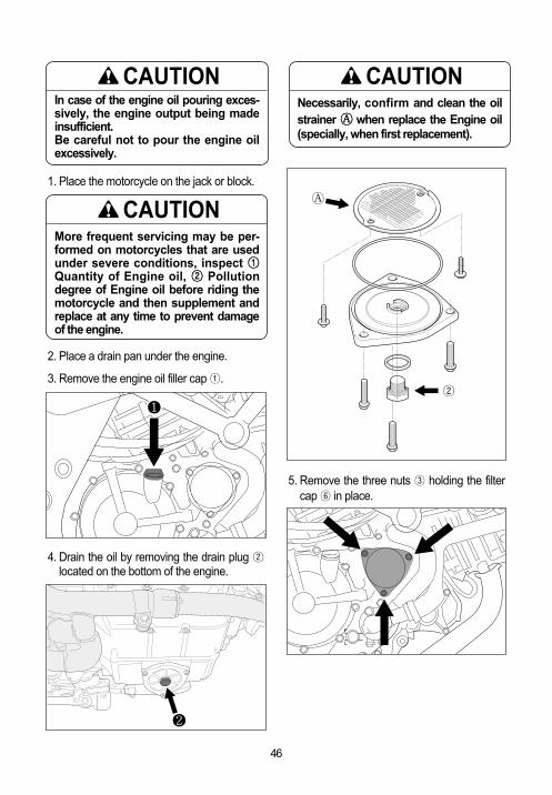
5. Remove the three nuts ③ holding the filtercap ⑥ in place.
2. Place a drain pan under the engine.
3. Remove the engine oil filler cap ①.
4. Drain the oil by removing the drain plug ②located on the bottom of the engine.
�
More frequent servicing may be per-formed on motorcycles that are usedunder severe conditions, inspect ①①Quantity of Engine oil, ②② Pollutiondegree of Engine oil before riding themotorcycle and then supplement andreplace at any time to prevent damageof the engine.
CAUTION
Necessarily, confirm and clean the oilstrainer �� when replace the Engine oil(specially, when first replacement).
CAUTION
� ②
��
1. Place the motorcycle on the jack or block.
In case of the engine oil pouring exces-sively, the engine output being madeinsufficient.Be careful not to pour the engine oilexcessively.
CAUTION
�

47
●● OIL FILTER INSTALLATION
HYOSUNG
16510HN910
OUTSIDE
LUSTER MATERIAL
INSERTION DIRECTION
Insert the filter so that surface of the fil-ter hole turn toward the engine.
CAUTION
When install the oil filter, necessarily,““ HYOSUNG”” character and““16510HN910””part’’s NO. install towardthe outside, otherwise can damage theengine.
CAUTION
6. Replace the engine oil filter ⑦ with a newone.
7. Before replacing the engine oil filter cap ⑥,be sure to check that the engine oil filterspring ④ and the “O”ring ⑤ are installedcorrectly. Use new “O”ring each time theengine oil filter element is replaced.
8. Replace the oil filter cap ⑥ and tighten thenuts securely but do not over tighten them.
Engine oil and exhaust pipes can be hotenough to burn you.Wait until the oil drain plug and exhaustpipes are cool enough to touch withbare hands before draining oil.
WARNING
New and used oil and solvent can behazardous. Children and pets may beharmed by swallowing new or usedengine oil or solvent. Continuous con-tact with used engine oil has been foundto cause skin cancer in laboratory ani-mals. Brief contact with used oil or sol-vent may irritate skin.
●● Keep new and used oil and solventaway from children and pets.
●● Wear a long-sleeve shirt and water-proof gloves.
●● Wash with soap if oil or solvent con-tact your skin.
WARNING
④
③ ⑦
③
⑤
⑥

48
10. Operate the engine a few seconds byidling speed.
Inspect the oil leakage at the oil filter cap.
11. Confirm the oil level with the oil level lensafter waiting about a minute next to stop-ping the engine.
The oil level is located between the“Lower line(L)”and the“Upper line(F)”.
When below the“Lower line(L)”, refill theoil between the“Lower line(L)”and the
“Upper line(F)”.
9. Replace the drain plug and tighten itsecurely. This time, insert the gasket nec-essarily. Pour fresh oil through the fillerhole. Approximately 3,200㎖ of oil will berequired.
Approximately 3,000㎖㎖ of oil must berequired when changing oil only withoutreplacing the oil filter.
CAUTION
In case of the engine oil pouring exces-sively, the engine output being madeinsufficient.Be careful not to pour engine oil.
CAUTION
COOLANT
◉◉ COOLANT LEVEL
The coolant should be kept between the“F”(FULL) and “L”(LOW) level lines in thereservoir tank at all times. Inspect the levelevery time before riding while the motorcy-cle vertically. If the coolant is found lowerthan the “L”level line, add properly mixedcoolant in the following way :
If the reservoir tank is emptied, pour theengine coolant to the reservoir tank andradiator.
1. Remove the front and rear seat.
2. Remove the filler cap and add properlymixed coolant through the filler holeuntil it reaches the “F”line.
Refer to the FUEL, ENGINE OIL ANDCOOLANT RECOMMENDATION section(14 page).

49
Engine coolant is harmful or fatal ifswallowed or inhaled.
Do not drink anti-freeze or coolantsolution. If swallowed, do not inducevomiting. Immediately contact a poi-son control center or a physician.Avoid inhaling mist or hot vapors ; ifinhaled, remove to fresh air.If coolant gets in eyes, flush eyes withwater and seek medical attention.Wash thoroughly after handling.Solution can be poisonous to ani-mals. Keep out of the reach of chil-dren and aminals.
WARNING
◉◉ CHANGING THE COOLANTChange the coolant every two years.
N O T EAdding only water will dilute the enginecoolant and reduce its effectiveness.Add 50:50 mixture of engine coolant andwater.
N O T EAbout 1.6ℓℓ of coolant will requiredwhen filling the radiator and reservoirtank.
◉◉ SIDE COWLING INNER(FOR 『『 』』& 『『 』』)
『 』&『 』have the“side cowling inner ①” at the rightside.
Use the “side cowling inner” to operatethe radiator cap ③.
To disassemble the “side cowling inner”,remove the two bolts ②.
『『 』』
『『 』』
Do not open the radiator cap when theengine is hot, as you may be injured byescaping hot liquid or vapor.
WARNING

50
1. The transmission is in neutral.2. The ignition switch is in the “ON”
position.3. The engine stop switch is in the “ ”
position.4. Moving the side stand to the fully
upper position.5. Pull in the clutch lever.6. Inspect every day once before riding
the motorcycle.
RIDING TIPS
STARTING THE ENGINE
Before attempting tostart the engine makesure:
The is equipped withthe side stand ignition interlock system.If the transmission is in neutral or sidestand up, you can only start the enginewith pulling in the clutch lever.This side stand ignition interlock systemprevents the motorcycle from beingstarted with side stand down.Make sure that the side stand igintioninterlock system is working properlybefore riding.
WARNING
These motorcycles always come on thehead lamp, meter lamp and tail lampwhen starting the engine.
CAUTION
Running the engine indoors or in agarage can be hazardous. Exhaust gas contains carbon monoxide,a gas that is colorless and odorless andcan cause death or severe injury.Only run the engine outdoors wherethere is a fresh air.
WARNING
Running the engine too long without rid-ing may cause the engine to overheat. Overheating can result in damage tointernal engine components and discol-oration of exhaust pipes.Shut the engine off if you cannot beginyour ride promptly.
CAUTION
Operation of the carburetor choke sys-tem is not necessary when the engine iswarm.
CAUTION
◉◉ When the engine is warm :1. Open the throttle grip 1/8 ~ 1/4.2. Push the starter switch.
◉◉ When the engine is cold :1. Turn the carburetor choke lever all the
way toward you.2. Close the throttle grip and push the
starter switch.3. Immediately after the engine starts,
return the choke lever halfway andwarm up the engine.
4. Return the choke lever all the way backto its disengaged position.
51
Do not engage the starting motor formore than five seconds at a time as itmay overheat the wiring harness andstarting motor.If the engine does not start after severalattempts, check the fuel supply and igin-tion system.(Refer to Page 78)
CAUTION STARTING OFF
Riding these motorcycles at excessivespeed increases your chances of losingcontrol of the motorcycle.This may result in an accident. Always ride within the limits of yourskills, your motorcycle, and the ridingconditions.
WARNING
Removing your hands from the handle-bars or feet from the footrests duringoperation can be hazardous. If youremove even one hand or foot from themotorcycle, you can reduce your abilityto control the motorcycle.Always keep both hands on the handle-bars and both feet on the footrests ofyour motorcycle during operation.
WARNING
Sudden side winds, which can occurwhen being passed by large vehicles, attunnel exits or in hilly areas, can upsetyour control.Reduce your speed and be alert to sidewinds.
WARNING

52
Pull the clutch lever in and pausemomentarily. Engage first gear by depress-ing the gearshift lever downward.
Turn the throttle grip toward you and atthe same time release the clutch lever gen-tly and smoothly. As the clutch engages,the motorcycle will start moving forward.To shift to the next higher gear, accelerategently, then close the throttle and pull theclutch lever in simultaneously. Lift thegearshift lever upward to select the nextgear and release the clutch lever and openthe throttle again.
Select the gears in this manner until sixthgear is reached.
Downshifting while the motorcycle isleaned over in a corner may cause rearwheel skid and loss of control.Reduce your speed and downshiftbefore entering corner.
WARNING
Do not operate the ignition switch of its““OFF””or ““LOCK””position or theengine stop switch of its ““ ””positionwhile driving at one’s pleasure.
WARNING
The transmission is provided to keep theengine operating smoothly in its normaloperating speed range. The gear ratioshave been carefully chosen to meet thecharacteristics of the engine. The ridershould always select the most suitable gearfor the prevailing conditions.
USING THE TRANSMISSION
Downshifting when engine speed is toohigh can ;●●cause the rear wheel to skid and lose
traction due to increased enginebraking, resulting in an accident ; or
●● force the engine to overrev in thelower gear, resulting in engine dam-age.
Reduce speed before downshifting.
WARNING
Revving the engine into the red zonecan cause severe engine damage.
Never allow the engine to rev into thered zone in any gear.
CAUTION

53
When climbing steep hills, the motorcyclemay begin to slow down and show lack ofpower. At this point you should shift to alower gear so that the engine will again beoperating in its normal power range. Shiftgear rapidly to prevent the motorcycle fromlosing momentum.
When riding down a steep hill, the enginemay be used for braking by shifting to alower gear.
Be careful, however, not to allow theengine to overrev.
RIDING ON HILLS STOPPING AND PARKING
1. Turn the throttle grip away from you toclose the throttle completely.
2. Apply the front and rear brakes evenlyand at the same time.
3. Downshift through the gears as roadspeed decreases.
4. Select neutral with the clutch leversqueezed towards the grip(disengagedposition) just before the motorcyclestops. Neutral position can be confirmedby observing the neutral indicator lamp.
Inexperienced riders tend to underutilizethe front brake. This can cause exces-sive stopping distance and lead to a col-lision. Using only the front or rear brakecan cause skidding and loss of control.
Apply both brakes evenly and at thesame time.
WARNING
Hard braking on wet, loose, rough, orother slippery surfaces can cause wheelskid and loss of control.
Brake lightly and carefully on slippery orirregular surfaces.
WARNING
Hard braking while turning may causewheel skid and loss of control.
Brake before you begin to turn.
WARNING

54
5. Park the motorcycle on a firm, flat sur-face where it will not fall over.
Following another vehicle too closelycan lead to a collision. As vehiclespeeds increase, stopping distanceincreases progressively.
Be sure you have a safe stopping dis-tance between you and the vehicle infront of you.
WARNING
A hot muffler can burn you. The mufflerwill be hot enough to burn you for sometime after stopping the engine.
Park the motorcycle where pedestriansor children are not likely to touch themuffler.
WARNING
6. Push down the key to the “OFF”posi-tion, and turn it to the “LOCK”positionafter come up again.
7. Remove the ignition key.
The opening explains how importantproper break-in is to achieve maximum lifeand performance from your new Hyosung.The following guidelines explain properbreak-in procedures.
Less than 3/4 throttle
Less than 1/2 throttle
Up to 1,600km (1,000miles)
Initial 800km (500miles)
★★ MAXIMUM THROTTLE OPENING RECOMMENDATIONS
The table below shows the maximumthrottle opening recommendation during thebreak-in period.
★★ AVOID CONSTANT LOW SPEEDOperating the engine at constant low
speed(light load) can cause parts to glazeand not seat in. Allow the engine to acceler-ate freely through the gears, withoutexceeding the recommended maximumlimits. Do not, however, use full throttle forthe first 1,600km(1,000 miles).
★★ VARY THE ENGINE SPEEDThe engine speed should be varied and
not held at a constant speed.This allows the parts to be “loaded”with
pressure and then unloaded, allowing theparts to cool.
This aids the mating process of the parts.It is essential that some stress be placed onthe engine components during break-in toensure this mating process.
Do not, though, apply excessive load onthe engine.
BREAK-IN

55
★★ BREAKING IN THE NEW TIRESNew tires need proper break-in to assure
maximum per formance, just as theengine does.
Wear in the tread surface by graduallyincreasing your cornering lean anglesover the first 160km(100miles) beforeattempting maximum performance. Avoidhard acceleration, hard cornering, and hardbraking for the first 160km(100miles).
★★ ALLOW THE ENGINE OIL TO CIR-CULATE BEFORE RIDINGAllow sufficient idling time after warm orcold engine start up before applying loador revving the engine. This allows timefor the lubricating oil to reach all criticalengine components.
★★ OBSERVE YOUR FIRST, ANDMOST 1,000km SERVICE
The 1,000km (600miles) service is themost important service your motorcyclewill receive.During break-in procedures, all of theengine components will have worn inand all of the other parts will have seatedin.All adjustments will be restored, all fas-teners will be tightened, and the dirtyengine oil and engine oil filter will bereplaced.
Failure to perform break-in of the tirescould cause tire slip and loss of control.Use extra care when riding on new tire.Perform proper break-in of the tire asdescribed in this section and avoid hardacceleration, hard cornering, and hardbraking for the first 160km(100miles).
WARNING
Service should may be peformed before1,000km(600miles) on motorcycle thatare used under severe conditions.
CAUTION
The 1,000km (600miles) service shouldbe performed as outlined in theINSPECTION AND MAINTENANCE sec-tion of this Owner’’s Manual. Pay partic-ular attention to the 『『CAUTION』』and
『『WARNING』』in that section.
CAUTION
Timely performance of the 1,000km(600miles) service will ensure optimumservice life and performance from theengine.

56
INSPECTION BEFORE RIDING
Before riding the motorcycle, be sure tocheck the following item.
Inspect every day once them before rid-ing motorcycle.
WHAT TOCHECK
Steering
Throttle
Clutch
Brakes
Suspension
Fuel
Drivechain
Tires
Engine oil
Coolingsystem
Lighting
HornEnginestop switchSide stand /lgnitioninterlockswitch
●● Smoothness●● No restriction of movement●● No play or looseness●● Correct play in the throttle
cable●● Smooth operation and pos-
itive return of the throttlegrip to the closed position
●● Correct lever play●● Smooth and progressive
action●● Fluid level in the reservoir to
be above “LOWER”line●● Correct pedal and lever
play●● No “sponginess”●● No fluid leakage●● Brake pads not to be worn
down to the limit lineSmooth movementEnough fuel for the planneddistance of operation●● Correct tension or slack●● Adequate lubrication●● No excessive wear or dam-
age●● Correct pressure●● Adequate tread depth●● No cracks or cutsCorrect level and pollutiondegree of engine oil●● Proper coolant level●●No coolant leakgeOperation of all lights and indi-catorsCorrect function
Correct function
Proper operation
CHECK FOR :

57
◉◉ LUBRICATION POINTSProper lubrication is important for smooth
and long life of each working part of yourmotorcycle and also for safe riding. It is agood practice to lubricate the motorcycleafter a long rough ride or after it gets wet inthe rain or after washing it.
Major lubrication points are indicated asfollows.
Improper maintenance or failure to per-form recommended maintenanceincreases the chance of an accident ormotorcycle damage.
WARNING
Using poor quality replacement partscan cause your motorcycle to wearmore quickly and may shorten its usefullife.Use only genuine Hyosung replacementparts or their equivalent.
CAUTION
The chart indicates the intervals betweenperiodic service in kilometers.
At the end of each interval, be sure toinspect, check, lubricate and service asinstructed.
If your motorcycle is used under highstress conditions such as continuous fullthrottle operation, or is operated in a dustyclimate, certain services should be per-formed more often to ensure reliability ofthe machine as explained in the mainte-nance section.
Your Hyosung dealer can provide youwith further guide lines.
Steering components, suspensions andrequire very special and careful servicing.For maximum safety we suggest that youhave these items inspected and serviced byyour authorized Hyosung dealer or a quali-fied service mechanic.
PERIODIC MAINTENANCE

58
① Clutch lever holder and clutch cable② Footrests pivot ③ Passenger footrests pivot ④ Drive chain ⑤ Side stand pivot and spring hook
⑥ Speedometer gear box ⑦ Front brake lever holder ⑧ Throttle cable⑨ Rear brake pedal pivot
- Motor oil - Grease

59
Interval Item
Clean every 3,000 km∙Replace every 12,000 kmTighten Tighten ─
Inspect Inspect ─
Tighten Tighten ─
─ ─ Remove carbonClean Clean ReplaceInspect Inspect ─
Replace every 4 yearsReplace Replace ─
Replace Replace ─
Inspect Inspect ─
Inspect Inspect ─
Inspect Inspect ─
Replace every 2 years─ Inspect ─
Replace every 4 years
◉◉ ENGINE
Air cleaner elementExhaust pipe bolts and muffler mounting bolts ★Valve clearance adjust ★Cylinder head bolt ★Cylinder head & Cylinder ★Spark plug
Fuel hose
Engine oil filterEngine oilThrottle cableIdle speed ★Clutch ★Engine coolant ★
Radiator hose ★
First1,000 km
Every6,000 km
Every12,000 km
Interval Item
Clean and lubricate every 1,000 kmInspect Inspect ─
Inspect Inspect ─
Replace every 4 yearsInspect Inspect ─
Replace every 2 yearsInspect Inspect ─
Inspect Inspect ─
─ Inspect ─
─ Inspect ─
Tighten Tighten ─
◉◉ CHASSIS
Drive chain ★Brake ★
TireSteering ★Front forks ★Rear shock absorber ★Chassis nuts and bolts ★
First1,000 km
Every6,000 km
Every12,000 km
★★= Ask your Hyosung dealer or qualified mechanic to do the maintenance items marked.
N O T E
Brake hose ★
Brake fluid ★

60
NO. NAME
Tool bag10 × 12 mm open end wrench14 × 17 mm open end wrenchSpark plug wrenchCombination screw driverScrew driver handleClamp wrenchClamp wrench handlePliersHexagon spanner 4mmHexagon spanner 6mm
1234567891011
①
②
③
④
⑤
⑥
⑦
⑧
⑨
⑩
⑪
Check if there is leakage from crankcase.
To assist you in the performance of peri-odic maintenance, a tool kit is supplied andis located under the front seat. The tool kitconsists of the following items.
INSPECTION AND MAINTENANCE
TOOL
ENGINE OIL
Inspect the fuel hose for damage and fuelleakage. If any defect are found the fuelhose must be replaced.
Replace the fuel hose every 4 years.
FUEL HOSE

61
Inspect the rear shock absorber for oilleakage and spring condition.
◉◉ INSPECTION OF BATTERY SOLUTIONLEVEL
MF(Maintenance Free) battery of airtighttype is used for these motorcycles.
It is not necessary to inspect or supple-ment battery fluid.
The battery is located under the frontseat.
However, have your dealer check thecharging condition of battery periodically.
● Check if there is any noise by bend offront fork while moving the handleupward and downward.
● Inspect whether the steering stem iswell assembled while moving front forkup/downwards and /or foreward/backward.
FRONT FORK
REAR SHOCK ABSORBER
BATTERY
●●Do not remove absolutely airtightcover as airtight type battery.
●●Keep after separate at the motorcyclefor the minimum of self electric dis-charge and electric leakage whendon’t use for a long time.
●●Remove the (--) negative terminalwhen keep intact at the motorcycle.
CAUTION
Check if there is leakage from fuel tank,fuel pump, fule cock, hose, carburetor.
Mop them up with a patch when washing.
GASOLINE
Check if there is leakage from the radiator,coolant hose.
COOLANT
Check if there is damage from the radiator.
RADIATOR
Check to see the radiator hose for crack,damage or engine coolant leakage.
If any defects are found, replace the radia-tor hose with new ones.
RADIATOR HOSE
RUBBER CAP OF CABLES
Inspect the exhaust pipe and muffler jointfor loosening.
EXHAUST PIPE AND MUFFLER

62
If the air cleaner element has becomeclogged with dust, intake resistance willincrease with a resultant decrease in poweroutput and an increase in fuel consumption.If riding under severe conditions must becleaned or replaced more frequently thanmaintenance schedule. Check and cleanthe air cleaner element periodically accord-ing to the following procedure.
1. The air cleaner is located under the fueltank.Remove the fuel tank.
2. Remove the four screw ①3. Pull up the air cleaner cover, and the air
cleaner element ②.
AIR CLEANER
If the air cleaner element is polluted, willoccur to starting go out, outputinsuffiency, combustion effciencydecline, and sooty smoke(black smoke).This appearence is occurred at first toclean the air cleaner element and con-firm.
CAUTION
◉◉ CLEAN OF BATTERY TERMINALClean the battery terminal when it is
dusty or rusted.1. Set the ignition switch “OFF”position.2. Disassemble the front seat, disassem-
ble the (+) positive battery wire after the(-) negative battery wire.Remove the battery.
3. Clean the terminal.If there is white dust, clean it with warmwater.
4. Assemble the battery wires and greasethe terminal lightly.
●● Keep the battery away from fires.●● When disassemble the battery wire,
take off �� terminal first with the igni-tion switch ““OFF””position. Whenassemble, �� terminal first.
●● Fasten certainly the battery wires.●● Incorrect installation of the battery
will reverse the terminal positionresulting in possible electrical sys-tem damage due to incorrect batterylead connection.
●● Never charge a battery while still inthe machine as damage may resultto the battery or regulator/rectifier.
CAUTION

63
4. Clean the air cleaner element for the fol-lowing :1) When the air cleaner element clean
with the air gun, necessarily blow atthe inside by compressed air.
2) Carefully examine the air cleaner ele-ment for tears during cleaning.Replace it with a new one if it is torn.
3) Assemble the element completely ordamage severely the engine.
4) Be careful not to allow water to goinside the air cleaner element.
Before and during the cleaning opera-tion, inspect the element for tears. Atorn element must be replaced.Be sure position the element snugly andcorrectly, so that no incoming air willbypass it.Remember, rapid wear of piston ringsand cylinder bore is often caused by adefective or poorly fitted element.
CAUTION
●●When the assembly of air cleaner ele-ment is not completely done, dustscan go inside and damage severelyengine.
●●Be careful not to allow water to gointo the element while washing.
CAUTION
●●Assemble the element completely ordamage severely the engine.
●●Be careful not to allow water to goinside the air cleaner element.
CAUTION
More frequent servicing may be per-formed on motorcycles that are usedunder severe conditions, also clean theair cleaner element when replacing theoil to prevent damage of the engine.
CAUTION
①
②

64
PLUG REPLACEMENT GUIDE
Hotter type
Standard type
Colder type
CR7E
CR8E
CR9E
Readjust the spark plug gap to 0.7�0.8mm (0.028 � 0.032 in) by using a sparkplug gap thickness gauge.
0.7~0.8mm(0.028�0.032 in)
●●Do not over torque or cross threadthe spark plug or the aluminumthreads of the cylinder head will bedamaged.Do not allow contaminants to enterthe engine through the spark plugholes when the plug is removed.
●●The standard spark plug for thesemotorcycles has been carefullyselected to meet the vast majority ofall operational ranges. If the sparkplug color indicates that other than astandard spark plug be used, it isbest to consult your Hyosung dealerbefore selecting an alternate plug orheat range. The selection of animproper spark plug can lead tosevere engine damage.
CAUTION
Inspect the plug ① and drain water and oilat the periodic maintenance interval.
The air cleaner oil drain plug ① is locatedbeneath the air cleaner case.
Remove the carbon deposits periodicallyfrom the spark plug with a piece of hard wireor pin.
SPARK PLUG
◉◉ AIR CLEANER OIL DRAIN PLUG
①
65
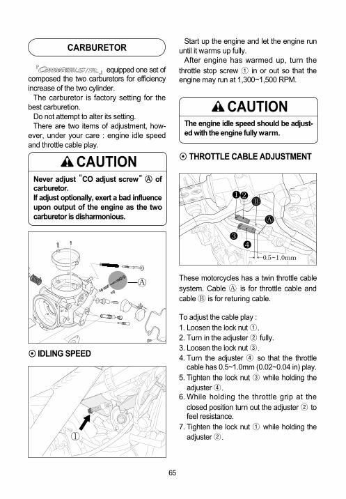
equipped one set ofcomposed the two carburetors for efficiencyincrease of the two cylinder.
The carburetor is factory setting for thebest carburetion.
Do not attempt to alter its setting.There are two items of adjustment, how-
ever, under your care : engine idle speedand throttle cable play.
◉◉ IDLING SPEED
Start up the engine and let the engine rununtil it warms up fully.
After engine has warmed up, turn thethrottle stop screw ① in or out so that theengine may run at 1,300~1,500 RPM.
These motorcycles has a twin throttle cablesystem. Cable � is for throttle cable andcable � is for returing cable.
To adjust the cable play :1. Loosen the lock nut ①.2. Turn in the adjuster ② fully.3. Loosen the lock nut ③.4. Turn the adjuster ④ so that the throttle
cable has 0.5~1.0mm (0.02~0.04 in) play.5. Tighten the lock nut ③ while holding the
adjuster ④.6. While holding the throttle grip at the
closed position turn out the adjuster ② tofeel resistance.
7. Tighten the lock nut ① while holding theadjuster ②.
◉◉ THROTTLE CABLE ADJUSTMENT
CARBURETOR
The engine idle speed should be adjust-ed with the engine fully warm.
CAUTION
Never adjust ““CO adjust screw””�� ofcarburetor.If adjust optionally, exert a bad influenceupon output of the engine as the twocarburetor is disharmonious.
CAUTION
①
�
66
��
� �
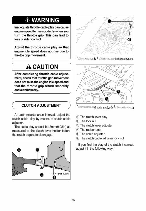
① The clutch lever play② The lock nut③ The clutch lever adjuster ④ The rubber boot⑤ The cable adjuster⑥ The clutch cable adjuster lock nut
If you find the play of the clutch incorrect,adjust it in the following way :
At each maintenance interval, adjust theclutch cable play by means of clutch cableadjuster.
The cable play should be 2mm(0.08in) asmeasured at the clutch lever holder beforethe clutch begins to disengage.
CLUTCH ADJUSTMENT
After completing throttle cable adjust-ment, check that throttle grip movementdoes not raise the engine idle speed andthat the throttle grip return smoothlyand automatically.
CAUTION
Inadequate throttle cable play can causeengine speed to rise suddenly when youturn the throttle grip. This can lead toloss of rider control.
Adjust the throttle cable play so thatengine idle speed does not rise due tothrottle grip movement.
WARNING �
�
�
�
『『 』』& 『『 ((SSttaannddaarrdd ttyyppee))』』
『『 ((SSppoorrttss ttyyppee))』』& 『『 』』

67
�� CLUTCH CABLE ADJUSTMENT● A basis adjustment be allowed by the
clutch lever adjuster ③.● Loosen the clutch lever adjuster ③.● Screw the lock nut ② clockwise fully,
after finishing adjustment.● After end of adjustment, tighten the lock
nut ② and cover the rubber boot ④.● If not adjust by the adjuster ③, loosen
the clutch cable adjuster lock nut ⑥.● Turn the clutch cable adjuster ⑤ in or
out to acquire the specified play.● After end of adjustment, tighten the lock
nut ⑥.● The clutch cable should be lubricated
with a light weight oil whenever it isadjusted.
2 mm (0.08 in)Clutch cable play ①①
◉◉ Insepcting the Drive Chain When inspecting the chain, look for the fol-lowing:● Loose pins● Damaged rollers● Dry or rusted links● Missing X-O ring seals● Kinked or binding links● Excessive wear● Improper chain adjustment
If you find something wrong with the drivechain condition or adjustment, correct theproblem if you know how. If necessary, con-sult your authorized Hyosung dealer.
Damage to the drive chain means that thesprockets may also be damaged. Inspectthe sprockets for the following :● Excessively worn teeth● Broken or damaged teeth● Loose sprocket mounting nuts
The chain may require more frequentadjustment that it is with periodic mainte-nance depending upon your riding condi-tions.
Check the chain every 1,000km.
DRIVE CHAIN
Riding with the chain in poor conditionor improperly adjusted can lead to anaccident.
Inspect, adjust, and maintain the chainproperly before each ride, according tothis section.
WARNING

68
1. Place the motorcycle on the jack or block. 2. Loosen the axle nut ①.3. Loosen the lock nut ②.4. Adjust the slack in the drive chain by
adjuster ③ as turning toward the left andright.
5. For alignment of the rear sprocket andthe front sprocket, there are referencemark ④ on the same position.After aligning and adjusting the slack inthe drive chain to 20~30mm (0.79~1.18in), retighten the lock nut and axle nutsecurely and perform a final inspection.
The drive chain for these motorcycles ismade of the special material.The chain should be replaced with aRK525XSO for .Use of another chain may lead to prema-ture chain failure.
CAUTION
The drive chain should be inspectedevery time before riding.Excessive chain slack could cause thechain to come off the sprockets andresult in accident or serious enginedamage.
CAUTION
20~30mm(0.79~1.18 in)
If you find any of these problems with yoursprocket, consult your Hyosung dealer.
◉◉ DRIVE CHAIN ADJUSTMENTAdjust the drive chain slack to the proper
specification. The chain may require morefrequent adjustments than periodic mainte-nance schedule depending upon your ridingconditions.
Chain adjust in the following way.
Good Excessivewear
The two sprockets should be inspectedfor wear when a new chain is installedand replace them if necessary.
CAUTION
�
�
�
�

69
◉◉DRIVE CHAIN CLEANING AND OILING
This drive chain has special “X-O rings”.Clean and oil the chain periodically, as fol-
lows:1. Clean the chain with kerosene. If the
chain tends to rust, the interval must beshortened. Kerosene is a petroleumproduct and will provide some lubrica-tion as well as cleaning action.
Kerosene can be hazardous. Keroseneis flammable. Children or pets may beharmed from contact with kerosene.
Keep flames and smoking materialsaway from kerosene. Keep children andpets away from kerosene.If swallowed, do induce vomiting. Call aphysician immediately.Dispose of used kerosene properly.
WARNING
Be careful not to touch the muffler whenit is hot : a hot muffler can burn you.
WARNING
Cleaning the chain with gasoline orcommercial cleaning solvents can dam-age “X-O rings”and ruin the chain.
Clean the drive chain with keroseneonly.
CAUTION
utilizes front and reardisk brakes.
Properly operating the brake systems arevital to safe riding. Be sure to perform thebrake inspection requirements as sched-ules.
The brakes should be inspected at period-ic inspection by your authorized Hyosungdealer.
◉◉ BRAKE FLUIDBe sure to check the brake fluid level inthe master cylinder. If the level was foundto be lower than the lower mark whileholding the motorcycle upright, replenishwith the proper brake fluid that meetsHyosung’s requirements.As the brake pads wear, the fluid level willdrop to compensate for the new position ofbarke pads.Replenishing the master cylinder to con-sidered normal periodic maintenance.
BRAKES
2. After thoroughly washing the chain andallowing it to dry, oil the links with aHyosung chain lube or an equivalent.
Some drive chain lubricants contain sol-vents and additives which could dam-age the “X-O rings”in your chain.
Use Hyosung chain lube or an equiva-lent that is specifically intended for usewith “X-O rings”chains.
CAUTION

70
These motorcycles uses glycol-basedbrake fluid. Do not use or mix different types ofbrake fluid, otherwise serious damagewill result in the brake system.Use DOT4 brake fluid. Do not spill any brake fluid on paintedor plastic surfaces as it will damagethe surface severely.Never use any brake fluid that hasbeen stored in a used or unsealedcontainer. Never reuse brake fluid leftover from the last servicing andstored for long period as it absorbsmoisture from the air.
CAUTION
Brake fluid may be harmful if swallowedor if it comes in contact with skin oreyes. Contact your doctor immediatelyif brake fluid is swallowed and inducevomiting. If brake fluid gets into the eyesor in contact with the skin, flush thor-oughly with plenty of water.
WARNING
[Front Brake]
[Rear Brake]

71
◉◉ BRAKE PADSInspect the front brake pads by nothing
whether or not the friction pads are worndown to the grooved limit line. If a pad isworn to the grooved limit line it must bereplaced with a new one by your authorizedHyosung dealer or qualified servicemechanic.
Limit line
�
[Front Brake]
[Rear Brake]
The front and rear brake system bereplaced the brake hose or the brakefluid according to periodic inspectionchart by your authorized Hyosung deal-er for safety as in times of operating athigh pressure.
CAUTION
Riding with worn brake pads will reducebraking performance and will increaseyour chance of having accident. Inspectbrake pad wear before each use. Askyour Hyosung dealer or qualifiedmechanic to replace brake pads if anypad is worn to the limit.
WARNING
After replaced the front or rear brakepads, the brake lever and pedal pull andrelease several times so that it is settingat the original place. Then, do not ride the motorcycle untilloperating the brake fluid and becomingthe brake distance.
CAUTION
Inspect every day in the following point atthe brake system.① Brake fluid leakage of the front and rear
brake system.② Leak or damage of the brake hose.③ Operating of the brake lever and pedal.④ Wear of the front and rear brake pads.

72
◉◉ FRONT BRAKE LAMP SWITCHThe front brake lamp switch is located
beneath the front brake lever. Loosen theswitch fitting screws and adjust the timing bymoving the switch body forward or back-ward.
◉◉ REAL BRAKE LAMP SWITCHThe rear brake lamp switch is located at
right-side of the engine.Move the switch up or down to adjust it
until the switch operates and turns on thebrake lamp after the brake pedal begins tobe depressed.
◉◉ REAR BRAKE FLUID SUPPLY1. Place the motorcycle on a level surface
and keep the handlebars straight.2. Clean the brake fluid reservior around not
to allow dust to get inside of it.3. Turn the cap to the counter - clockwise.4. Replenish with brake fluid to the upper
line.
N O T EThe recommended brake fluid
: DOT4
5. Fasten the cap.
Do not spill any brake fluid on painted orplastic surfaces as it will damage thesurface severely.
CAUTION
◉◉ BRAKE DISK INSPECTION.Check the brake disk for damage or cracks.
◉◉ FRONT BRAKE FLUID SUPPLY1. Place the motorcycle on a level surface
and keep the handlebars straight.2. Clean the brake fluid reservior around not
to allow dust to get inside of it.3. Loosen the screw and open the cap.4. Replenish with brake fluid to the upper
line.
N O T EThe recommended brake fluid : DOT4
5. Fasten the cap.

73
TIRE
Inspect the tire pressure and the tirethread depth periodically.
Inspect frequently the tire pressure for thesafety and the tire life.
◉◉ TIRE PRESSUREInsufficient air pressure in the tires not
only hasten tire wear but also seriouslyaffects the stability of the motorcycle.
Under-inflated tires make smooth corner-ing difficult and over-inflated tires decreasethe amount of tire in contact with the groundwhich can lead to skids and loss of control.Be sure that the tire pressure is within thespecified limits at all times.
Tire pressure should only be adjustedwhen the tire is cold.
If you see the problem with the tire, adjustthe pressure with the pressure gauge.
Failure to follow these warnings mayresult in an accident due to tire failure.The tires on your motorcycle form thecrucial link between your motorcycleand the road.
Follow these instructions ;●●Check tire condition and pressure,
and adjust pressure before each ride.●●Avoid overloading your motorcycle.●●Replace a tire when worn to the spec-
ified limit, or if you find damage suchas cuts or cracks.
●●Always use the size and type of tiresspecified in this owner’s manual.
WARNING
◉◉ CRACKS AND CUTS
Check if 1) there are visible cracks and cuts.2) there are pebbles stuck.
OVER NORMAL SHORT
TIRE PRESSURE(COLD INFLATION)
FRONT
REAR
NORMAL RIDING
SOLO RIDING DUAL RIDING
2.50 kg/㎠245 kpa36.0 psi
2.50 kg/㎠245 kpa36.0 psi
2.25 kg/㎠221 kpa33.0 psi
2.25 kg/㎠221 kpa33.0 psi
If there are some problem with the tirepressure or cracks and cuts, it willdecrease the riding stability and lead toflat tire.
CAUTION
SCREW
WORN,CRACK
FOREIGNMATERIAL

74
Operating the motorcycle with excessivelyworn tire will decrease riding stability andcan lead to loss of control.
Inspect storage of tire thread’s depth bythe 『tire wear indicator』.
Replace the front and rear tires at oncewhen appear the 『tire wear indicator』.
◉◉ TIRE TREAD CONDITION
◉◉ REAR AXLE NUTInspect the rear axle shaft and jointing nut
for loosening.
◉◉ TIRE REPLACEMENT●● FRONT TIRE REPLACEMENT1. Place the motorcycle on the jack or
block.
●● REAR TIRE REPLACEMENT1. Place the motorcycle on the jack or
block.
2. Loosen the four front axle pinch bolt ①(right and left).
3. Loosen the front axle ②.4. Carefully position a jack or block under
engine and raise until the front wheel isslightly off the ground.
5. Draw out the axle shaft.6. Slide the front wheel forward.7. To reinstall the wheel assembly,
reverse the sequence as described.
The standard tire on is 120/60-ZR 17 55W for front, and 160/60-ZR 17 69W for rear.The use of a tire other than standardmay cause trouble. It is highly recommended to use thestandard tire supplied by Hyosung.
CAUTIONImproper jacking may cause damageto the oil filter.Do not apply the jack head to the oilfilter when jacking up the motorcycle.
CAUTION
①
Tire wear indicator
Tire wear indicator mark
�TWI
TW
I
TW
I
TWI
� �
�
/ /

75
HILO
Brake / Tail lamp
Turn signal lamp
License plate lamp
Head lamp 12V - H4 : 60W × 112V - H4 : 55W × 1
12V - 21/5W × 1
12V - 10W × 4
12V - 5W × 1
12V - H1 : 55W × 112V - H3 : 55W × 1
←
←
←
NAMES
Requirement electric power of the lampshown in the following chart.
When replace the damaged lamp, alwaysuse the equal capacity.
The use of a lamp other than rules maycause to excessive at the electric system orto damage the lamp.
REPLACEMENT OF THE LAMP
2. Loosen the rear axle ①.3. Carefully position a jack or block under
engine and raise until the rear wheel isslightly off the ground.
4. Draw out the rear axle shaft.5. Pull the rear wheel assembly rear
ward.6. To replace the wheel, reverse the com-
plete sequence listed.
A hot muffler can burn you.The muffler will be hot enough to burnyor for some time after stopping theengine.Wait until the muffler cools to avoidburns.
WARNING
&
CAPACITY

76
2. Disconnect the headlamp coupler.3. Remove the dust cover ② and socket
spring ③.4. After removing the bulb at the socket,
replace the new bulb.5. To install the headlamp, reverse the
above sequence.
The use of a lamp other than rules maycause to occur the vehicle fire and todamage electric parts.Surely use only the lamp of propercapacity.
CAUTION
③ ②
◉◉ HEAD LAMP ( ))
1. Remove the three screw ① (right, leftand bottom) and the headlamp assembly.
①
◉◉ HEAD LAMP (( & ))
We suggest that you have 『 』& 『 』’s head lamp bulb replaced byyour authorized Hyosung dealer or a qualifiedservice machanic.

77
◉◉ TURN SIGNAL LAMP
1. Remove the lens by removing thescrew.
2. Push the bulb, turn it to the counter-clockwise, and pull it out.
3. After stick in the new lamp, assemble thelens.
◉◉ TAIL/BRAKE LAMP
1. Remove the rear seat.To remove the rear seat, insert the igni-tion key into the lock and turn it clock-wise.
Overtightening the screws may causethe lens to crack.
CAUTION ◉◉ LICENSE PLATE LAMP
Overtightening the screws may causethe lens to crack.
CAUTION
�
1. Remove the socket under the rear fend-er.
2. Push the bulb, turn it to the counter-clockwise, and pull it out.
3. To fit the replacement of bulb, push it inand turn it of to the clockwise while push-ing.
2. Turn the socket to the counter-clockwiseand pull it out at the lamp housing.
3. Push the bulb, turn it to the counter-clockwise, and pull it out.
4. To fit the replacement of bulb, push itin and turn it to the clockwise whilepushing.
�

78
◉◉ TROUBLE SHOOTINGIf the engine refuses to start, perform the
following inspections to determine thecause.
●● Fuel Supply Check① Is there enough fuel in the fuel tank?② Make sure there is enough fuel reaching
the carburetor from the fuel pump.●● Ignition System Check① Remove a spark plug and reattach to the
spark lead.② While holding the spark plug firmly
against the crankcase of the engine,push the starter switch with the ignitionswitch in the “ON”position, the enginestop switch in the “ ”position, thetransmission in neutral, the side stand upand the clutch disengaged.If the igntion system is operating proper-ly, a blue spark should jump a cross thespark plug gap.
③ If there is no spark, clean the spark plug.Replace it if necessary. Retry the aboveprocedure with the cleaned spark plug ornew one.
④ If there is still no spark, consult yourHyosung dealer for repairs.
WHEN THE ENGINE REFUSES TO START
Performing the spark test improperlycan cause a high voltage electricalshock or an explosion.
Avoid performing this check if you arenot familiar with this procedure, or if youhave a heart condition or wear a pace-maker. Keep the spark plug away fromthe spark plug hole during this test.
WARNING
◉◉ FUSE
The fuse box is located behind the rearseat. If the engine suddenly stops while run-ning or any electrical system fails to operatethen the fuse must be checked.
In case a fuse blows there is a 30A formain and 15A for head lamp spare fuse.
● 30A main fuse protects all electrical cir-cuits.
● 15A head lamp fuse protects the headlamp and high beam indicator lamp.
Never use other than specified 30A or15A fuse.Installing a fuse of incorrect rating mayseriously damage the electrical system.You should consult your Hyosung deal-er or a qualified service mechanic imme-diately.
CAUTION
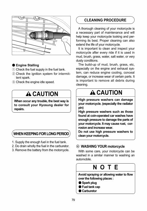
79
●● Engine Stalling① Check the fuel supply in the fuel tank.② Check the ignition system for intermit-
tent spark.③ Check the engine idle speed.
1. Supply the enough fuel in the fuel tank.2. Do drain wholly the fuel in the carburetor.3. Remove the battery from the motorcycle.
When occur any trouble, the best way isto consult your Hyosung dealer forrepairs.
CAUTION
WHEN KEEPING FOR LONG PERIOD
A thorough cleaning of your motorcycle isa necessary part of maintenance and willhelp keep your motorcycle looking and per-forming its best. Proper cleaning can alsoextend the life of your motorcycle.
It is important to clean and inspect yourmotorcycle after every ride if it is used inmud, brush, grass, water, salt water, or verydusty conditions.
The build-up of mud, brush, grass, etc,especially on the engine and exhaust sys-tem, can reduce engine cooling, concealdamage, or increase wear of certain parts. Itis important to remove all debris duringcleaning.
◉◉ WASHING YOUR motorcycle With some care, your motorcycle can be
washed in a similar manner to washing anautomobile.
CLEANING PROCEDURE
High pressure washers can damageyour motorcycle. (especially the radiatorpin)High pressure washers such as thosefound at coin-operated car washes haveenough pressure to damage the parts ofyour motorcycle. It may cause rust, cor-rosion and increase wear.Do not use high pressure washers toclean your motorcycle.
CAUTION
N O T EAvoid spraying or allowing water to flowover the following places :●●Spark plug ●●Fuel tank cap●●Carburetor

80
Use a garden hose at low pressure toremove the majority of dirt or other debris.Hand wash your motorcycle with a mildsoap or detergent and water. Try to thor-oughly remove all dirt and debris withoutexcessive water pressure. Cloth rags,washing mitts or cleaning brushes can beused, be careful with brushes as they mayscratch plastic or painted surfaces. Rinsethe motorcycle thoroughly with clean water.Dry all areas using a chamois or softabsorbent cloth.
◉◉ INSPECTION AFTER CLEANING Remove the rags or wrapping from the
exhaust pipe. For extended life of yourmotorcycle, lubricate according to
“GENERAL LUBRICATION”section.
Follow the procedures in the “INSPEC-TION BEFORE RIDING”section to checkyour motorcycle for any problems that mayhave arisen during your last ride.
Operating motorcycle with wet brakescan be hazardous.Wet brakes may not provide as muchstopping power as dry brakes. Thiscould lead to an accident.Test your brakes after washing motor-cycle, while riding at slow speed. If nec-essary, apply brakes several times to letfriction dry out the pads.
WARNING

81
L A B E L
NOTE :“ ”= means the invisable parts.
①
②
③

82
①
②
③

83
ENGINE
DIMENSIONS AND DRY MASS
SPECIFICATIONS
Overall length
Overall width
Overall height
Wheelbase
Ground clearance
Mass
2,060mm (81.1 in)
740mm (29.1 in)
1,090mm (42.9 in)
1,435mm (56.5 in)
150mm (5.9 in)
195kg (430 lbs)
←
←
1,125mm (44.3 in)
←
←
215kg (474 lbs)
←
655mm (25.8 in)
←
←
←
←
←
←
←
←
130mm (5.1 in)
219kg (483 lbs)
(Standard type) (Sports type)
Type
Number of cylinder
Bore
Stroke
Piston displacement
Carburetor
Starter system
Four-stroke, DOHC, Liquid-cooled
V-2 cylinder
81.5mm (3.21 in)
62.0mm (2.44 in)
647㎤ (39.5 in3)
BDSR39 TYPE(DOUBLE)
ELECTRIC STARTER
←
←
←
←
←
←
←
←
←
←
←
←
←
←
←
←
←
←
←
←
←
(Standard type) (Sports type)
TRANSMISSION
Clutch
Reduction ratio
Drive chain
Transmission
Wet multi-plate type
2.93
RK525XSO
1st : 2.46
2nd : 1.60
3rd : 1.32
4th : 1.13
5th : 0.96
6th : 0.85
←
←
←
←
←
←
←
←
←
←
←
←
←
←
←
←
←
←
←
←
←
←
←
←
←
←
←
(Standard type) (Sports type)

84
CHASSIS
Front suspension
Rear suspension
Caster
Trail
Steering angle
Front tire size
Rear tire size
Front brake
Rear brake
Telescopic type
Swingarm type
25.5。
85mm (3.35 in)
30。(right & left)
120/60 - ZR 17 55W
160/60 - ZR 17 69W
Double disk
Disk
←
←
←
74mm (2.91 in)
27。(right & left)
←
←
←
←
←
←
←
←
←
←
←
←
←
←
←
←
←
←
←
←
←
←
(Standard type) (Sports type)
ELECTRICAL
Ignition type
Ignition timing
Spark plug
Battery
Fuse
Head lamp
License plate lamp
Turn signal lamp
Brake / Tail lamp
“Igniter”type
5。B.T.D.C. at 1,500rpm
CR8E
12V 12Ah (MF)
Main : 30A, Head lamp : 15A
[ HI ] 12V - H4 : 60W×1
[ LO ] 12V-H4 : 55W×1
12V - 5W×1
12V - 10W×4
12V - 21/5W×1
←
←
←
←
←
[ HI ] 12V - H1 : 55W×1
[ LO ] 12V-H3 : 55W×1
←
←
←
←
←
←
←
←
←
←
←
←
←
←
←
←
←
←
←
←
←
←
←
(Standard type) (Sports type)
CAPACITIES
Fuel tank
Engine oil
17.0 ℓ
3,000 ㎖ (Replace)
3,200 ㎖ (Oil filter replace)
3,400 ㎖ (Overhaul)
←
←
←
←
←
←
←
←
←
←
←
←
(Standard type) (Sports type)

85
MEMO

MEMO
86

MEMO
87

Prepared by
HYOSUNG MOTORS & MACHINERY INC.
2nd Ed. JAN. 2005.
Printed in KOREA