gtawad
DESCRIPTION
camTRANSCRIPT

1
Computer Aided Manufacturing

2Dr. Mohamed Ahmed Awad
2
GROUP TECHNOLOGY
• Group technology is a manufacturing • Technique and philosophy to increase
production efficiency by exploiting the “underlying sameness” of component
• Shape, Dimensions, Process Route, Etc.
3Dr. Mohamed Ahmed Awad
3
• Group Technology is the realization that many problems are similar, and that by grouping similar problems, a single solution can be found to a set of problems thus saving time and effort.

4Dr. Mohamed Ahmed Awad
4
• GT is the beginning stage of Computer-Aided Process Planning

5Dr. Mohamed Ahmed Awad
5
Why Group Technology
• Average lot size decreasing
• Part variety increasing
• Increased variety of materials
• With diverse properties
• Requirements for closer
• tolerances

Dr. Mohamed Ahmed Awad 6
FLEXIBILITY
PRODUCTION CAPACITY
TRANSFERLINE
SPECIAL SYSTEM
FLEXIBLEMANUFACTURING
SYSTEM
MANUFACTURINGCells
STD. AND GEN.MACHINERY
VO
LU
ME
HIGH
VARIETYLOW HIGH

Dr. Mohamed Ahmed Awad 7
Everyday Examples• 1. Fast food chains• 2. Doctors, dentists and also manufacturing

8Dr. Mohamed Ahmed Awad
8
Production Family

9Dr. Mohamed Ahmed Awad
9
Benefits Of Group Technology
Reduction In • Throughput time• Set-up time• Overdue orders• Production floor space• Raw material stocks• In-process inventory• Capital expenditures• Tooling costs• Engineering time and costs• New parts design• New shop drawings• Total number of drawings

Dr. Mohamed Ahmed Awad 10
GT affects most every operating and staff function. It is more than merely a technique, but a total
Manufacturing philosophy.
GT
DESIGNENGINEERI
NGDATA
PROCESSING
MAINTENANCE
TOOL ENGINEERING
ESTIMATING
INDUSTRIALRELATIONS
QUALITYCONTROL
R & D
COSTACCOUNTING
SALES
INVENTORY
PLANNING
PURCHASING
ASSEMBLY
MANAGEMENT
MFG.ENGINEERING
SHIPPING &RECEIVING

11Dr. Mohamed Ahmed Awad
11
Techniques To Form Part Families
• 1. Tacit judgment or visual inspection
• 2. Production Flow Analysis
• 3. Classification And Coding

12Dr. Mohamed Ahmed Awad
12
1. Tacit judgment or visual inspection
• May use photos or part prints
• Utilizes subjective judgment

Dr. Mohamed Ahmed Awad 13
Visual MethodVisual Method
Parts grouped into families using a visual method
Parts are grouped according to their similarities in the geometric shape
Dependent on personal preference ( 주관적 ) Applicable when the number of parts is
rather limited13

14Dr. Mohamed Ahmed Awad
14
2. Production Flow Analysis
• Uses information contained on the route sheet (therefore only mfg. Info)
• Parts grouped by required processing

Dr. Mohamed Ahmed Awad 15
Cluster analysis 15

Dr. Mohamed Ahmed Awad 16
Cluster Analysis MethodCluster Analysis Method
Grouping objects into homogeneous Grouping objects into homogeneous clusters(groups) based on the object clusters(groups) based on the object featuresfeatures
Grouping : parts into part families (PFs) Grouping : parts into part families (PFs)
machines into machine cells machines into machine cells (MCs)(MCs)
To model the GT problem, To model the GT problem, threethree clustering formulation are usedclustering formulation are used Matrix formulation Matrix formulation Mathematical programming formulation Mathematical programming formulation Graph formulationGraph formulation
16

Dr. Mohamed Ahmed Awad 17
Result of groupingResult of grouping
Physical cell vs Logical Physical cell vs Logical (virtual) cell(virtual) cell
17

Dr. Mohamed Ahmed Awad 18
18

Dr. Mohamed Ahmed Awad 19
19

20Dr. Mohamed Ahmed Awad
20
3. Classification And Coding
• Codes geometry/design and mfg. Info about a component
• Codes are alphanumeric strings
• Easier to use for other analyses

Dr. Mohamed Ahmed Awad 21
Coding MethodCoding Method
Parts are first classified based on Parts are first classified based on featuresfeatures (characteristics) (characteristics)
Using a coding system : numerical or Using a coding system : numerical or alphanumerical codealphanumerical code
Three basic Three basic typestypes of coding systems of coding systems Monocode (tree structure)Monocode (tree structure) PolycodePolycode HybridHybrid
21

Dr. Mohamed Ahmed Awad 22
22

23Dr. Mohamed Ahmed Awad
23
Types Of Classification And Coding Systems
GT coding can benefit many facets of the Firm and fall into one of 3 categories:
• 1. Systems based on part design Attributes
• 2. Systems based on part mfg. Attributes
• 3. Systems based on design and mfg. Attributes

Dr. Mohamed Ahmed Awad 24
Examples:
Part Mfg. Attributes• Major processes• Minor operations• Fixtures needed
Part Design Attributes• Basic external shape• Basic internal shape• Material

25Dr. Mohamed Ahmed Awad
25
Major GT Code structures
• 1. Monocode (or hierarchical structure)
• 2. Polycode (Or Chain-type Structure)
• 3. Mixed Code

26Dr. Mohamed Ahmed Awad
26
1. Monocode (or hierarchical structure)
A code in which each digit amplifies the
information given in the previous digit
• Difficult to construct
• Provides a deep analysis
• Usually for permanent information

27Dr. Mohamed Ahmed Awad
27
2. Polycode (Or Chain-type Structure)
Each digit is independent of all others, presents information not dependent On previous ones
Easier to accommodate Change

28Dr. Mohamed Ahmed Awad
28
3. Mixed Code
Has some digits forming monocodes, but
strings them together in the general
Arrangement of a polycode

Dr. Mohamed Ahmed Awad 29
UN
F t
hre
ad
Tra
nsm
issi
on
Hierarchical Structure
Hydraulic Electrical
Mechanical
32XX
321X
322X
No
thre
adU
NC
thread
3222
323X
Power
Receiving
3232
3231 3233
3221 3223

30Dr. Mohamed Ahmed Awad
30
3. Mixed Code
• Has some digits forming monocodes, but strings them together in the general
• Arrangement of a polycode

Dr. Mohamed Ahmed Awad 31MonocodePolycode Polycode
Hybrid Structure

32Dr. Mohamed Ahmed Awad
32
Proliferation Of Parts
Selection of optical instrument parts in one company, Illustrating the similarity between certain components

33Dr. Mohamed Ahmed Awad
33
Conceptual design
Coding (rough model)
Retrieval existing designs
Existing designs
Design modification
New Design
Design archive
Retrieve designs of similarshape or function and usethem as the examples.
Design concept can be coded.
Code is a rough model of theconceptual design.

Dr. Mohamed Ahmed Awad 34
Technique:
1. Determine part and machine requirements
2. Numerically code each partGeometry (& size)MaterialOther specifications (tolerance, Surface finish)
3. Form a family of similar parts which use (Largely) the same set of machine tools
4. Lay out of each cell (a group of machine Tools) to make a family of parts
5. Design group tooling

Dr. Mohamed Ahmed Awad 35
Example:
Thirteen parts with similar manufacturing Process requirements but different Design attributes

Dr. Mohamed Ahmed Awad 36
Functional Layouts Are Inefficient
PROCESS-TYPE LAYOUT
Lathe Milling Drilling
Grinding
Assembly
Receiving andShipping
L
L L
L
L
L
L
L M
MM
M M
M
A A
A A
D
D D
D
G
G
G
G G
G

Dr. Mohamed Ahmed Awad 37
Group Technology Layout
Shipping
L L M D
L M D
G
L M GG
A A
Receiving
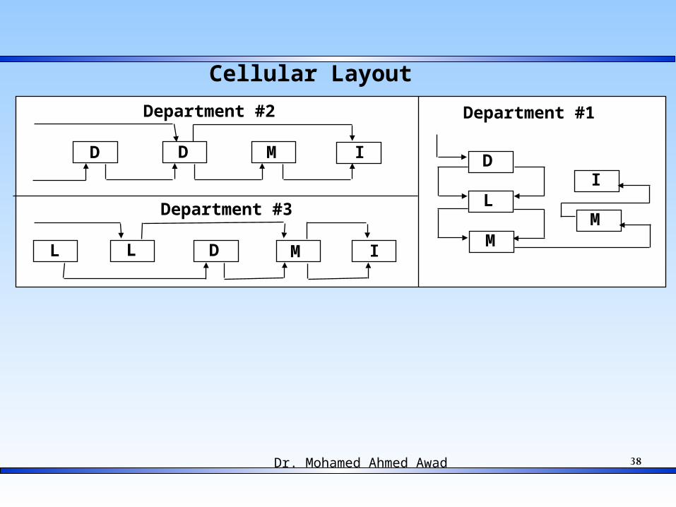
Dr. Mohamed Ahmed Awad 38
Department #2
Department #3
Department #1
D D M I
D ML L I
D
M
LM
I
Cellular Layout

Dr. Mohamed Ahmed Awad 39
1st Digitpart class
Positionswith adigit
2nd Digitmain shape
3rd Digitrotationalmachining
4th Digitplane surface
matching
5th Digitadditional
holes teeth &forming
Form Code
Opitz coding and classification system.
(Reprinted with permission from H. Opitz, A Classification System to Describe Workpieces, Pergamon Press.)
Special
Non
-rot
atio
nal
Special
Rot
atio
nal
9
8
7
6
5
4
3
2
1
0Internal
shapeelement
Rotationalmachining
Main bore & rotationalmachining
Other holesand teeth
Other holesteeth andforming
Other holesteeth andforming
Machiningof planesurfaces
Machiningof planesurfaces
Machiningof planesurfaces
External shape
element
Main shape
Main shape
Main shape
Main shape
Supplim-entarycode
Digit6 7 8 9
Dim
ensi
ons
Mat
eria
lO
rigi
nal s
hape
of
raw
mat
eria
lsA
ccu
racy

40Dr. Mohamed Ahmed Awad
40
Examining Opitz Code:

41Dr. Mohamed Ahmed Awad
41
Examining Opitz Code:
This Form code is the Opitz Code Solution on this shaft- like part

42Dr. Mohamed Ahmed Awad
42
Examining Opitz Code:

43Dr. Mohamed Ahmed Awad
43
• GT schemes are developed for specific applications.
• GT coding is basically a case analysis of possible part shapes.
Digit Meaning Code
1Rotational part, L/D ratio > 0.5
1
2 Step to one end 1
3Internal bore w/o
shape element1
4No external plane
surface0
5 Gear teeth 6
Sample part for GT coding “11106”