guide for autoconfig user configurable screens · levelpro user guide, p/n 1-0702-039 ... calc...
TRANSCRIPT

Part of Thermo Fisher Scientific
Density and Level HART Ops
Operation Guide P/N 1-0700-1023
Revision A

Density and Level HART Ops
Operation Guide P/N 1-0700-1023
Revision A


© 2015 Thermo Fisher Scientific Inc. All rights reserved.
“Microsoft” and “Windows” are either registered trademarks or trademarks of Microsoft Corporation in the United States and/or other countries.
All other trademarks are the property of Thermo Fisher Scientific Inc. and its subsidiaries.
Thermo Fisher Scientific Inc. (Thermo Scientific) makes every effort to ensure the accuracy and completeness of this manual. However, we cannot be responsible for errors, omissions, or any loss of data as the result of errors or omissions. Thermo Scientific reserves the right to make changes to the manual or improvements to the product at any time without notice.
The material in this manual is proprietary and cannot be reproduced in any form without expressed written consent from Thermo Scientific.


Thermo Fisher Scientific Density and Level HART Ops v
Revision History
Revision Level Date Comments
A 09-2015 Initial release per ERO 8709.

Thermo Fisher Scientific Density and Level HART Ops vii
Contents Chapter 1 Introduction .......................................................................................... 1-1
Associated Documentation .................................................................. 1-1 Density Application ............................................................................ 1-2 Level Application ................................................................................ 1-3
Chapter 2 HART Protocol Overview ....................................................................... 2-1
Chapter 3 Wiring & Connections .......................................................................... 3-1
Chapter 4 HART Masters ...................................................................................... 4-1
Chapter 5 MS2011 DD Menu Structure ................................................................. 5-1 Device Setup Menu ............................................................................. 5-1
Process Variables Menu .................................................................... 5-1 Diagnostic/Service Menu ................................................................. 5-1 Basic Setup Menu ............................................................................ 5-2 MS2011 Setup Menu ....................................................................... 5-2
Application Setup Menu ............................................................... 5-2 Application Live Data Menu ......................................................... 5-3 Quick Setup Menu........................................................................ 5-3 Detailed Setup Menu .................................................................... 5-5
Review Menu ................................................................................. 5-14
Chapter 6 Physical Analog I/O Calibration ............................................................ 6-1 Analog Input Calibration .................................................................... 6-2 Current Output Calibration ................................................................ 6-4
Chapter 7 Level Standardization & Calibration ...................................................... 7-1 Perform Standardization ..................................................................... 7-1 Perform Calibration ............................................................................ 7-4
Chapter 8 Density Standardization & Calibration .................................................. 8-1 Perform Standardization ..................................................................... 8-1 Perform Calibration ............................................................................ 8-5

Contents
viii Density and Level HART Ops Thermo Fisher Scientific
Chapter 9 Menu Samples ..................................................................................... 9-1 Online Menu ...................................................................................... 9-1 Device Setup Menu ............................................................................. 9-1 Process Variables Menu ....................................................................... 9-2
Configure Process Variables Menu ................................................... 9-2 Diagnostic/ Service Menu ................................................................... 9-2
Commands Method ......................................................................... 9-3 Loop Test Method ........................................................................... 9-3 D/A Trim Method ........................................................................... 9-4 Status Info Menu ............................................................................. 9-5
Basic Setup Menu ............................................................................... 9-5 Range Values Menu ......................................................................... 9-5 Device Information Menu ................................................................ 9-6 Update FLASH Method .................................................................. 9-6
MS2011 Setup Menu .......................................................................... 9-7 Application Setup Menu .................................................................. 9-7
App1:Setup Menu ......................................................................... 9-7 Modify Application .................................................................... 9-8
Det Map ....................................................................................... 9-8 Live Data Menu ............................................................................... 9-9
Measurements Menu ..................................................................... 9-9 Totals Menu ................................................................................. 9-9
Quick Setup Menu......................................................................... 9-10 Quick Setup, Density ..................................................................... 9-10
Density Setup Menu ................................................................... 9-10 Material Setup .......................................................................... 9-11 Meas#1 Setup Menu ................................................................ 9-12 Pipe Info Menu ........................................................................ 9-12
TempComp Setup Menu ............................................................ 9-12 Eqn1 Coeffs Menu ................................................................... 9-13 Eqn2 Coeffs Menu ................................................................... 9-13
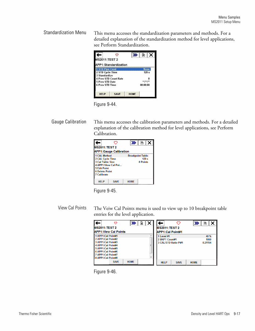
Standardization Menu ................................................................. 9-13 Gauge Calibration Menu ............................................................ 9-14
View Cal Points Menu ............................................................. 9-14 Calc Slope Corrn Factor ........................................................... 9-14
Quick Setup, Level ......................................................................... 9-15 Level Setup .................................................................................. 9-15
Level Setup ............................................................................... 9-15 Standardization Menu ................................................................. 9-17 Gauge Calibration ....................................................................... 9-17
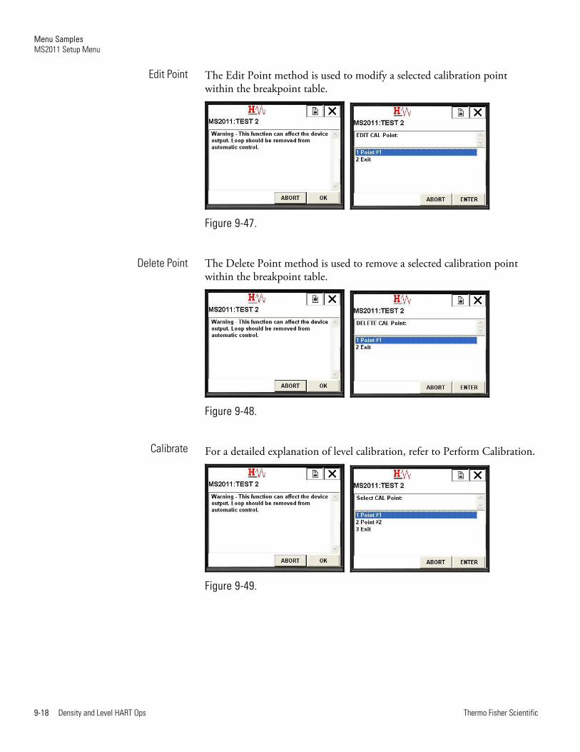
View Cal Points ....................................................................... 9-17 Edit Point ................................................................................ 9-18 Delete Point ............................................................................. 9-18 Calibrate .................................................................................. 9-18
Detailed Setup Menu ..................................................................... 9-19 System Control Menu ................................................................. 9-19
Contents
Thermo Fisher Scientific Density and Level HART Ops ix
System Status Menu .................................................................... 9-19 Software IDs Menu .................................................................. 9-20 Reference Volts Menu .............................................................. 9-20 IO Info Menu .......................................................................... 9-20
Mode/Fault Alarm Setup Menu .................................................. 9-21 System Alarm Setup Menu ....................................................... 9-22 Output A Faults Setup Menu ................................................... 9-23 Output B Faults Setup Menu ................................................... 9-24 Output C Faults Setup Menu .................................................. 9-24 Application #1 Menu ............................................................... 9-25 View Fault Status Menu ........................................................... 9-25
Commands Menu ....................................................................... 9-27 Physical IO Menu ....................................................................... 9-27
Current/Voltage Input Menu ................................................... 9-27 Digital Input Menu .................................................................. 9-30 Current Output Menu ............................................................. 9-32 Relay Output Menu ................................................................. 9-34
Detector Menu ............................................................................ 9-36 Detector #1 Menu.................................................................... 9-36
Application Menu ....................................................................... 9-46 Density Menu .......................................................................... 9-46 Level Menu .............................................................................. 9-59
Review .............................................................................................. 9-66 Device Vars Menu .......................................................................... 9-67 APPn:Review Menu ....................................................................... 9-67


Thermo Fisher Scientific Density and Level HART Ops 1-1
Chapter 1 Introduction
The Thermo Scientific MS2011 is designed to provide both reliable and accurate level and density measurements. With HART protocol, the gauge also provides users with access to control or program parameters via a host system, such as AMS, or locally using an Emerson 475 Hand Held Terminal (HHT).
The gauge consists of a source head containing the radioisotope source and the detector-transmitter. The radioisotope source emits gamma radiation that passes through the process material. The detector measures the energy of the radiation arriving at the detector after passing through the process material and vessel/pipeline walls. The gauge determines the level or density of the process material by measuring the amount of radiation arriving at the detector, which varies with the level or density of the process material.
Note This guide contains information specific to applications using the MS2011 with HART protocol. For information on the standard MS2011, reference the MS2011 user guides listed in Associated Documentation.
DensityPRO NAI installation guide, P/N 1-0702-015
DensityPRO installation guide, P/N 1-0702-144
DensityPRO Measurement Systems user guide, P/N 1-0702-016
LevelPRO installation guide, P/N 1-0702-040
LevelPRO user guide, P/N 1-0702-039
HART Field Device Specification, P/N 1-0700-1016
Gamma Radiation Safety Guide, P/N 717904
AssociatedDocumentation

Introduction Density Application
1-2 Density and Level HART Ops Thermo Fisher Scientific
When configured for density applications, the MS2011 can measure the density of almost any liquid, slurry (solid material in a carrier fluid), emulsion (two different fluids), or solution (a solute material dissolved in a solvent fluid).
After the gauge calculates the process material density, it can convert the measurement into a number of forms.
For slurries, the gauge can provide measurements based on the ratio of solid to carrier. Similar measurements can be made for emulsions and solutions.
By inputting flow data, the gauge can generate mass flow measurements. It can also accept a 4–20 mA current output from a magnetic flow sensor. For applications that require temperature compensation, the gauge accepts a temperature input to compensate the density measurement for changes in process temperature.
The gauge consists of the source head, which contains the radioisotope source, and the detector-transmitter, which contains the scintillator detector, and electronics. The radioisotope source emits gamma radiation that passes through the process material. The detector measures the energy of the radiation arriving at the detector after passing through the process material and vessel walls. The gauge determines the density of the process material by measuring the amount of radiation arriving at the detector, which varies with the density of the process material.
Figure 1-1. DensityPRO
Density Application
Introduction Level Application
Thermo Fisher Scientific Density and Level HART Ops 1-3
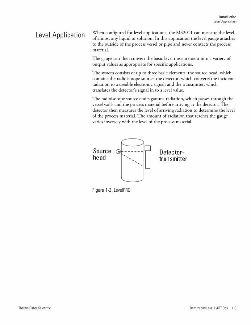
When configured for level applications, the MS2011 can measure the level of almost any liquid or solution. In this application the level gauge attaches to the outside of the process vessel or pipe and never contacts the process material.
The gauge can then convert the basic level measurement into a variety of output values as appropriate for specific applications.
The system consists of up to three basic elements: the source head, which contains the radioisotope source; the detector, which converts the incident radiation to a useable electronic signal; and the transmitter, which translates the detector’s signal in to a level value.
The radioisotope source emits gamma radiation, which passes through the vessel walls and the process material before arriving at the detector. The detector then measures the level of arriving radiation to determine the level of the process material. The amount of radiation that reaches the gauge varies inversely with the level of the process material.
Figure 1-2. LevelPRO
Level Application


Thermo Fisher Scientific Density and Level HART Ops 2-1
Chapter 2 HART Protocol Overview
The Highway Addressable Remote Transducer (HART) protocol is an industrial protocol that is superimposed on the 4–20 mA analog signal (Output C) of the MS2011. It is an open standard, and full details about HART can be obtained from the HART Communication Foundation at www.fieldcommgroup.org.
A complete definition of the protocol interface including all implemented commands can be found in the MS2011 HART Field Device Specification (P/N 1-0700-1016).

Thermo Fisher Scientific Density and Level HART Ops 3-1
Chapter 3 Wiring & Connections
Note This chapter provides wiring details for HART protocol operation. It is assumed that the instrument has already been installed. Refer to the installation guides listed in Associated Documentation for further information.
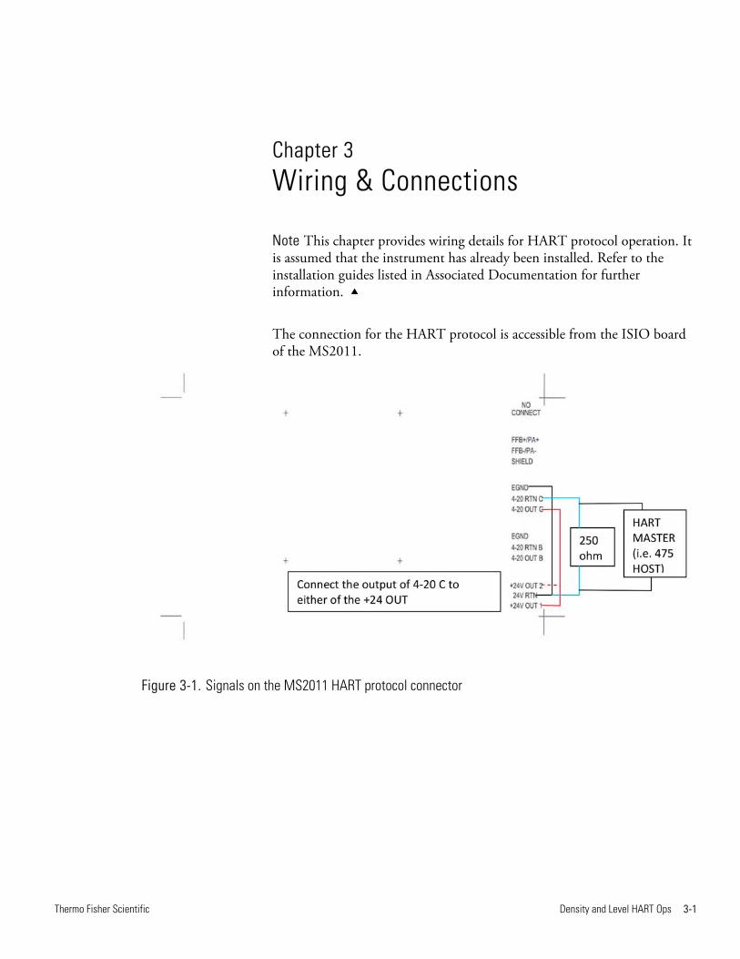
The connection for the HART protocol is accessible from the ISIO board of the MS2011.
Figure 3-1. Signals on the MS2011 HART protocol connector

Thermo Fisher Scientific Density and Level HART Ops 4-1
Chapter 4 HART Masters
Configuration/interrogation of the MS2011 via HART protocol can be accomplished using either a Primary or Secondary HART Master.
Primary masters can be host systems, such as AMS or SIMATIC PDM. Secondary masters are generally those such as an Emerson 475 Hand Held Terminal.
With each host, a DDL (Device Description Language) file will be required to fully configure the MS2011. The DDL for the MS2011 has been certified and so can be obtained from the HART Communication Foundation at www.fieldcommgroup.org.

Thermo Fisher Scientific Density and Level HART Ops 5-1
Chapter 5 MS2011 DD Menu Structure
This chapter describes the menu structure used for the MS2011 DD. The DD was primarily developed for use with an Emerson 475 Hand Held Terminal, so this section defines the menu structure based upon the LCD display of the HHT.
Chapter 9 shows example menus taken from a 475 simulator connected to an MS2011. A link to a sample view of each menu screen is given in the below tables.
Table 5-1.
Device Setup Menu
Process Variables Menu
Diagnostic/Service Menu
Basic Setup Menu
MS2011 Setup Menu
Review Menu
Table 5-2.
Process Variables Menu
Configure Process Variables Menu
Table 5-3.
Diagnostic/Service Menu
Commands Method
Loop Test Method
D/A Trim Method
Status Info Menu
Device SetupMenu
Process VariablesMenu
Diagnostic/ServiceMenu
MS2011 DD Menu Structure Device Setup Menu
5-2 Density and Level HART Ops Thermo Fisher Scientific
Table 5-4.
Basic Setup Menu
Range Values Menu
PV LRV
PV URV
Device Information Menu
Revision #s
Update FLASH Method
Table 5-5.
MS2011 Setup Menu
Application Setup Menu
Application Live Data Menu
Quick Setup Menu
Detailed Setup Menu
Update FLASH Method
Table 5-6.
Application Setup Menu
APP1:Setup
Modify Application
APP2:Setup
Modify Application
APP3:Setup
Modify Application
APP4:Setup
Modify Application
Det Map
Basic Setup Menu
MS2011 Setup Menu
Application Setup Menu
MS2011 DD Menu Structure Device Setup Menu
Thermo Fisher Scientific Density and Level HART Ops 5-3
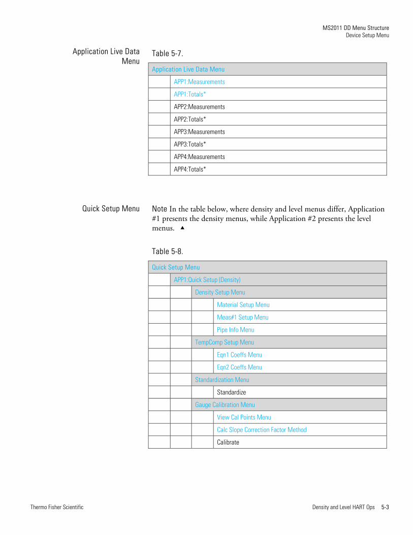
Table 5-7.
Application Live Data Menu
APP1:Measurements
APP1:Totals*
APP2:Measurements
APP2:Totals*
APP3:Measurements
APP3:Totals*
APP4:Measurements
APP4:Totals*
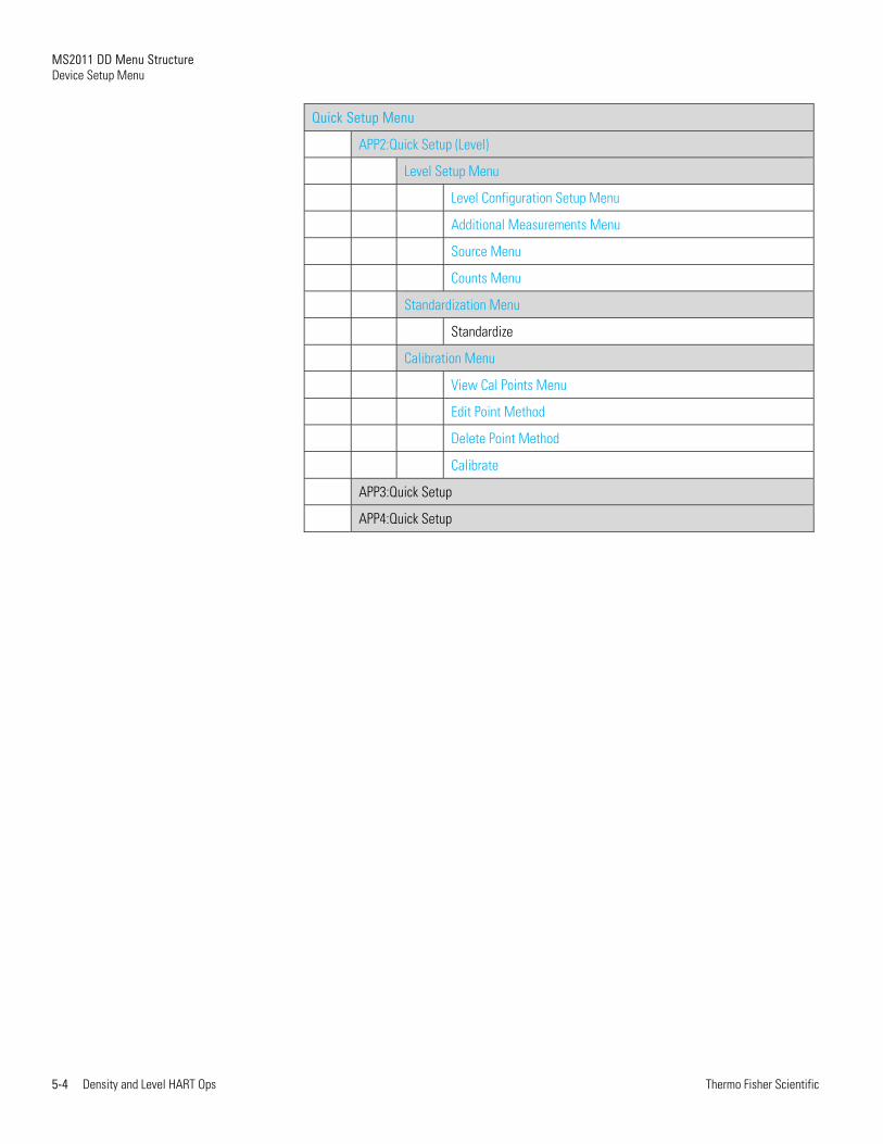
Note In the table below, where density and level menus differ, Application #1 presents the density menus, while Application #2 presents the level menus.
Table 5-8.
Quick Setup Menu
APP1:Quick Setup (Density)
Density Setup Menu
Material Setup Menu
Meas#1 Setup Menu
Pipe Info Menu
TempComp Setup Menu
Eqn1 Coeffs Menu
Eqn2 Coeffs Menu
Standardization Menu
Standardize
Gauge Calibration Menu
View Cal Points Menu
Calc Slope Correction Factor Method
Calibrate
Application Live DataMenu
Quick Setup Menu
MS2011 DD Menu Structure Device Setup Menu
5-4 Density and Level HART Ops Thermo Fisher Scientific
Quick Setup Menu
APP2:Quick Setup (Level)
Level Setup Menu
Level Configuration Setup Menu
Additional Measurements Menu
Source Menu
Counts Menu
Standardization Menu
Standardize
Calibration Menu
View Cal Points Menu
Edit Point Method
Delete Point Method
Calibrate
APP3:Quick Setup
APP4:Quick Setup
MS2011 DD Menu Structure Device Setup Menu
Thermo Fisher Scientific Density and Level HART Ops 5-5
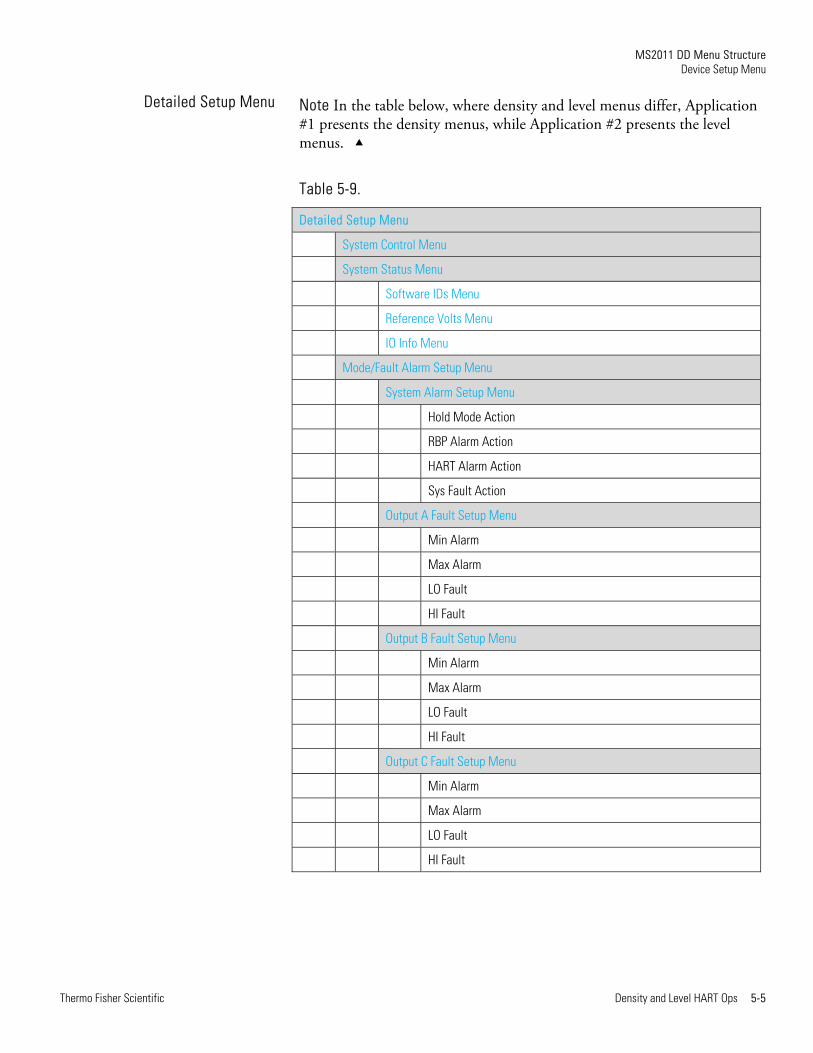
Note In the table below, where density and level menus differ, Application #1 presents the density menus, while Application #2 presents the level menus.
Table 5-9.
Detailed Setup Menu
System Control Menu
System Status Menu
Software IDs Menu
Reference Volts Menu
IO Info Menu
Mode/Fault Alarm Setup Menu
System Alarm Setup Menu
Hold Mode Action
RBP Alarm Action
HART Alarm Action
Sys Fault Action
Output A Fault Setup Menu
Min Alarm
Max Alarm
LO Fault
HI Fault
Output B Fault Setup Menu
Min Alarm
Max Alarm
LO Fault
HI Fault
Output C Fault Setup Menu
Min Alarm
Max Alarm
LO Fault
HI Fault
Detailed Setup Menu
MS2011 DD Menu Structure Device Setup Menu
5-6 Density and Level HART Ops Thermo Fisher Scientific
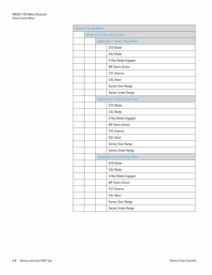
Detailed Setup Menu
Mode/Fault Alarm Setup Menu
Application 1 Faults Setup Menu
STD Mode
CAL Mode
X-Ray Mode Engaged
IBP Alarm Action
TOT Overrun
CAL Abort
Sensor Over Range
Sensor Under Range
Application 2 Faults Setup Menu
STD Mode
CAL Mode
X-Ray Mode Engaged
IBP Alarm Action
TOT Overrun
CAL Abort
Sensor Over Range
Sensor Under Range
Application 3 Faults Setup Menu
STD Mode
CAL Mode
X-Ray Mode Engaged
IBP Alarm Action
TOT Overrun
CAL Abort
Sensor Over Range
Sensor Under Range
MS2011 DD Menu Structure Device Setup Menu
Thermo Fisher Scientific Density and Level HART Ops 5-7
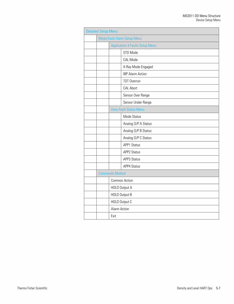
Detailed Setup Menu
Mode/Fault Alarm Setup Menu
Application 4 Faults Setup Menu
STD Mode
CAL Mode
X-Ray Mode Engaged
IBP Alarm Action
TOT Overrun
CAL Abort
Sensor Over Range
Sensor Under Range
View Fault Status Menu
Mode Status
Analog O/P A Status
Analog O/P B Status
Analog O/P C Status
APP1 Status
APP2 Status
APP3 Status
APP4 Status
Commands Method
Common Action
HOLD Output A
HOLD Output B
HOLD Output C
Alarm Action
Exit
MS2011 DD Menu Structure Device Setup Menu
5-8 Density and Level HART Ops Thermo Fisher Scientific
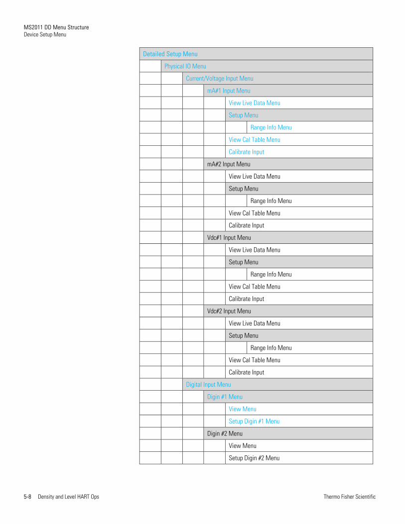
Detailed Setup Menu
Physical IO Menu
Current/Voltage Input Menu
mA#1 Input Menu
View Live Data Menu
Setup Menu
Range Info Menu
View Cal Table Menu
Calibrate Input
mA#2 Input Menu
View Live Data Menu
Setup Menu
Range Info Menu
View Cal Table Menu
Calibrate Input
Vdc#1 Input Menu
View Live Data Menu
Setup Menu
Range Info Menu
View Cal Table Menu
Calibrate Input
Vdc#2 Input Menu
View Live Data Menu
Setup Menu
Range Info Menu
View Cal Table Menu
Calibrate Input
Digital Input Menu
Digin #1 Menu
View Menu
Setup Digin #1 Menu
Digin #2 Menu
View Menu
Setup Digin #2 Menu
MS2011 DD Menu Structure Device Setup Menu
Thermo Fisher Scientific Density and Level HART Ops 5-9
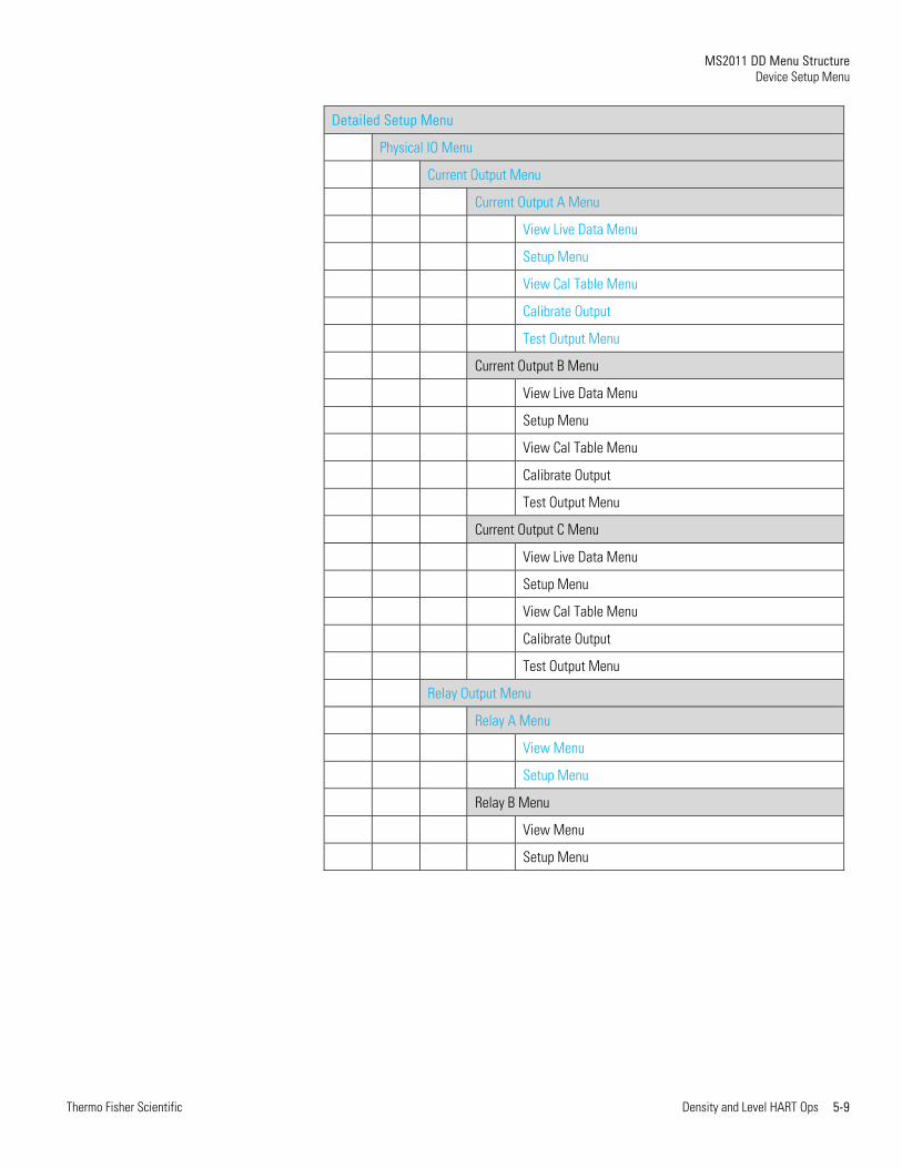
Detailed Setup Menu
Physical IO Menu
Current Output Menu
Current Output A Menu
View Live Data Menu
Setup Menu
View Cal Table Menu
Calibrate Output
Test Output Menu
Current Output B Menu
View Live Data Menu
Setup Menu
View Cal Table Menu
Calibrate Output
Test Output Menu
Current Output C Menu
View Live Data Menu
Setup Menu
View Cal Table Menu
Calibrate Output
Test Output Menu
Relay Output Menu
Relay A Menu
View Menu
Setup Menu
Relay B Menu
View Menu
Setup Menu
MS2011 DD Menu Structure Device Setup Menu
5-10 Density and Level HART Ops Thermo Fisher Scientific
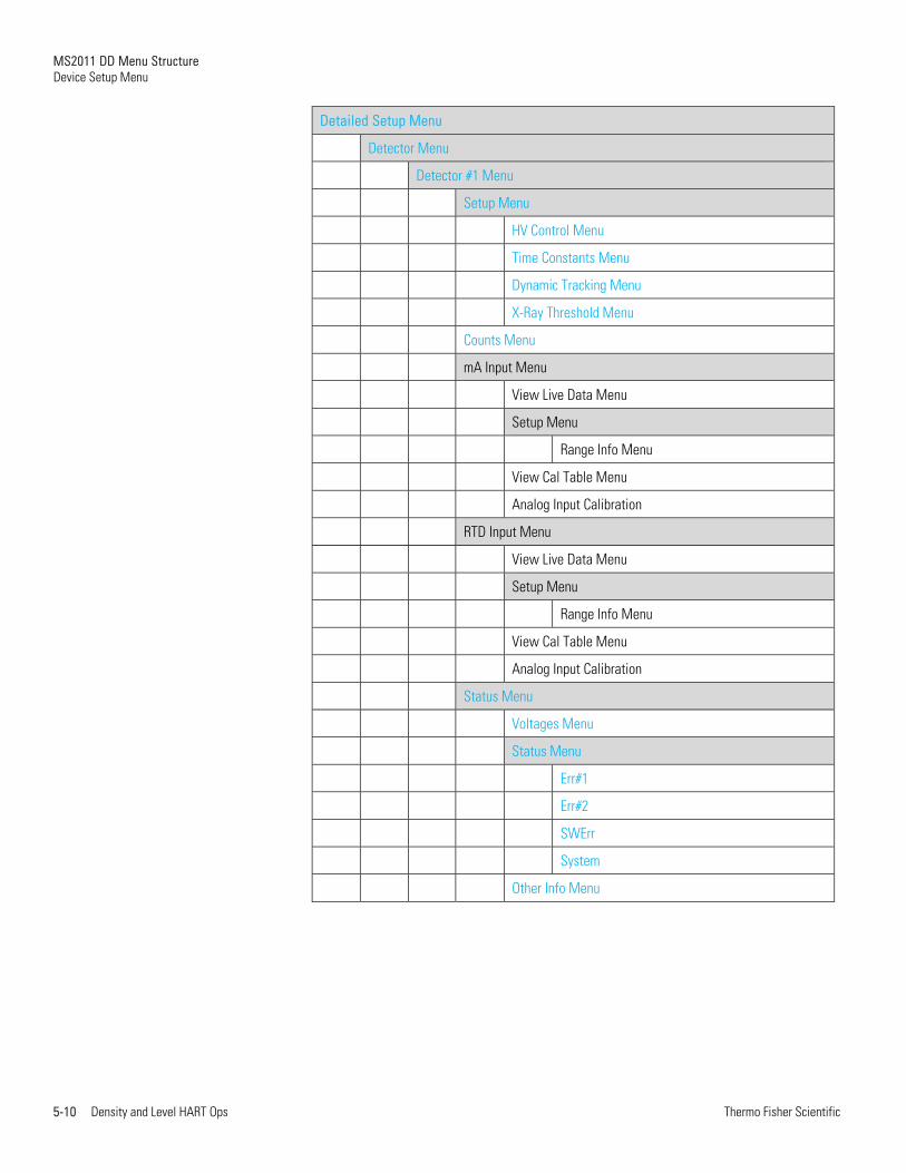
Detailed Setup Menu
Detector Menu
Detector #1 Menu
Setup Menu
HV Control Menu
Time Constants Menu
Dynamic Tracking Menu
X-Ray Threshold Menu
Counts Menu
mA Input Menu
View Live Data Menu
Setup Menu
Range Info Menu
View Cal Table Menu
Analog Input Calibration
RTD Input Menu
View Live Data Menu
Setup Menu
Range Info Menu
View Cal Table Menu
Analog Input Calibration
Status Menu
Voltages Menu
Status Menu
Err#1
Err#2
SWErr
System
Other Info Menu
MS2011 DD Menu Structure Device Setup Menu
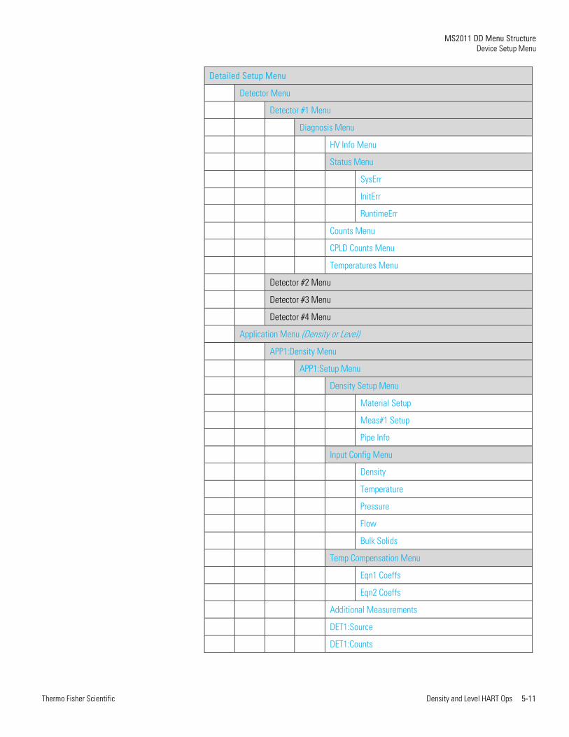
Thermo Fisher Scientific Density and Level HART Ops 5-11
Detailed Setup Menu
Detector Menu
Detector #1 Menu
Diagnosis Menu
HV Info Menu
Status Menu
SysErr
InitErr
RuntimeErr
Counts Menu
CPLD Counts Menu
Temperatures Menu
Detector #2 Menu
Detector #3 Menu
Detector #4 Menu
Application Menu (Density or Level)
APP1:Density Menu
APP1:Setup Menu
Density Setup Menu
Material Setup
Meas#1 Setup
Pipe Info
Input Config Menu
Density
Temperature
Pressure
Flow
Bulk Solids
Temp Compensation Menu
Eqn1 Coeffs
Eqn2 Coeffs
Additional Measurements
DET1:Source
DET1:Counts
MS2011 DD Menu Structure Device Setup Menu
5-12 Density and Level HART Ops Thermo Fisher Scientific
Detailed Setup Menu
Application Menu (Density or Level)
APP1:Density Menu
Standardization Menu
Standardize
Gauge Calibration Menu
View Cal Points Menu
Slope Correction Factor Method
Calibrate
Totals Menu
Enable All Totalizers
Tot#1 Setup
Tot#2 Setup
Tot#3 Setup
Tot#4 Setup
Actions Menu
Process Alarms Menu
Process Alarms 1-8
Process Alarm 1 Menu
Process Alarm 2 Menu
Process Alarm 3 Menu
Process Alarm 4 Menu
Process Alarm 5 Menu
Process Alarm 6 Menu
Process Alarm 7 Menu
Process Alarm 8 Menu

MS2011 DD Menu Structure Device Setup Menu
Thermo Fisher Scientific Density and Level HART Ops 5-13
Detailed Setup Menu
Application Menu (Density or Level)
APP1:Density Menu
Process Alarms Menu
Process Alarms 9-16
Process Alarm 9 Menu
Process Alarm 10 Menu
Process Alarm 11 Menu
Process Alarm 12 Menu
Process Alarm 13 Menu
Process Alarm 14 Menu
Process Alarm 15 Menu
Process Alarm 16 Menu
Status Menu
Application Menu (Density or Level)
APP2:Level Menu
APP1:Setup Menu
Level Setup Menu
Additional Measurements Menu
DET1:Source
DET1:Counts
Standardization Menu
Standardize
Gauge Calibration Menu
View Cal Points Menu
Edit Point
Delete Point
Calibrate
Actions Menu
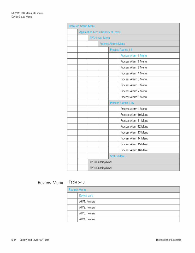
MS2011 DD Menu Structure Device Setup Menu
5-14 Density and Level HART Ops Thermo Fisher Scientific
Detailed Setup Menu
Application Menu (Density or Level)
APP2:Level Menu
Process Alarms Menu
Process Alarms 1-8
Process Alarm 1 Menu
Process Alarm 2 Menu
Process Alarm 3 Menu
Process Alarm 4 Menu
Process Alarm 5 Menu
Process Alarm 6 Menu
Process Alarm 7 Menu
Process Alarm 8 Menu
Process Alarms 9-16
Process Alarm 9 Menu
Process Alarm 10 Menu
Process Alarm 11 Menu
Process Alarm 12 Menu
Process Alarm 13 Menu
Process Alarm 14 Menu
Process Alarm 15 Menu
Process Alarm 16 Menu
Status Menu
APP3:Density/Level
APP4:Density/Level
Table 5-10.
Review Menu
Device Vars
APP1: Review
APP2: Review
APP3: Review
APP4: Review
Review Menu

Thermo Fisher Scientific Density and Level HART Ops 6-1
Chapter 6 Physical Analog I/O Calibration
This chapter provides information on how to calibrate the physical analog inputs and outputs available on the MS2011.
The MS2011 can support up to 12 analog inputs and 3 analog outputs.
Analog inputs are available on the following cards in the MS2011:
Two 4-20 mA on the CPU card
Two 0-10 V on the CPU card
One 4-20 mA for each detector (maximum of four)
One RTD input for each detector (maximum of four)
Analog outputs are available on the following cards in the MS2011:
One 4-20 mA on the CPU card
Two 4-20 mA on the ISIO card
The HART DD can be used to both configure and calibrate all inputs and outputs available on the MS2011.
Physical Analog I/O Calibration Analog Input Calibration
6-2 Density and Level HART Ops Thermo Fisher Scientific
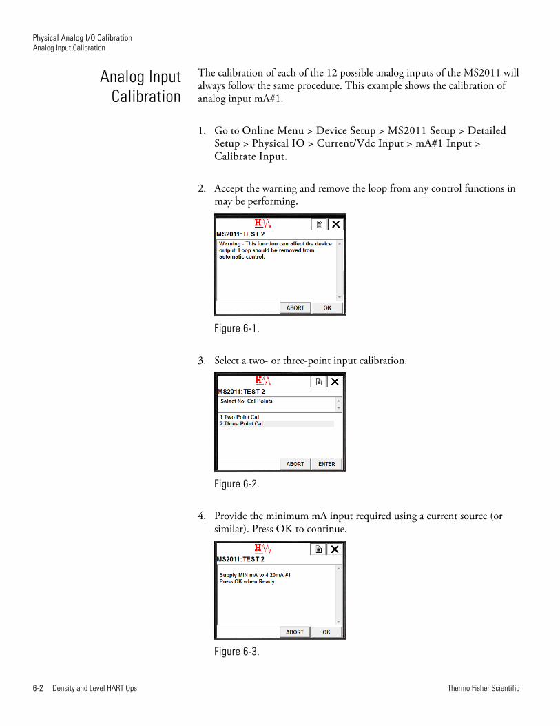
The calibration of each of the 12 possible analog inputs of the MS2011 will always follow the same procedure. This example shows the calibration of analog input mA#1.
1. Go to Online Menu > Device Setup > MS2011 Setup > Detailed Setup > Physical IO > Current/Vdc Input > mA#1 Input > Calibrate Input.
2. Accept the warning and remove the loop from any control functions in may be performing.
Figure 6-1.
3. Select a two- or three-point input calibration.
Figure 6-2.
4. Provide the minimum mA input required using a current source (or similar). Press OK to continue.
Figure 6-3.
Analog InputCalibration
Physical Analog I/O Calibration Analog Input Calibration
Thermo Fisher Scientific Density and Level HART Ops 6-3
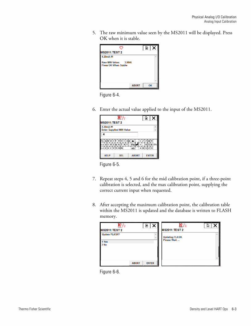
5. The raw minimum value seen by the MS2011 will be displayed. Press OK when it is stable.
Figure 6-4.
6. Enter the actual value applied to the input of the MS2011.
Figure 6-5.
7. Repeat steps 4, 5 and 6 for the mid calibration point, if a three-point calibration is selected, and the max calibration point, supplying the correct current input when requested.
8. After accepting the maximum calibration point, the calibration table within the MS2011 is updated and the database is written to FLASH memory.
Figure 6-6.

Physical Analog I/O Calibration Analog Output Calibration
6-4 Density and Level HART Ops Thermo Fisher Scientific
9. The loop may be returned to automatic control, if it is required and input calibration method is complete.
Figure 6-7.
The physical current outputs on the MS2011 are situated on both the CPU and ISIO cards. All of these outputs are configured and calibrated using the HART DD.
Follow the steps below to calibrate Output A using the 475 HHT.
1. Go to Online Menu > Device Setup > MS2011 Setup > Detailed Setup > Physical IO > Current Output > Current Output A > Calibrate Output.
2. Accept the warning and remove the loop from any control functions it may be performing.
Figure 6-8.
Analog Output Calibration
Physical Analog I/O Calibration Analog Output Calibration
Thermo Fisher Scientific Density and Level HART Ops 6-5
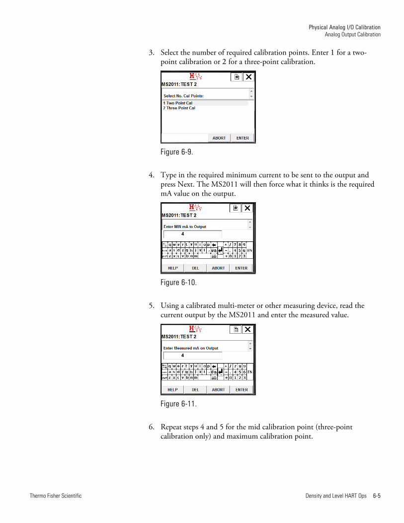
3. Select the number of required calibration points. Enter 1 for a two-point calibration or 2 for a three-point calibration.
Figure 6-9.
4. Type in the required minimum current to be sent to the output and press Next. The MS2011 will then force what it thinks is the required mA value on the output.
Figure 6-10.
5. Using a calibrated multi-meter or other measuring device, read the current output by the MS2011 and enter the measured value.
Figure 6-11.
6. Repeat steps 4 and 5 for the mid calibration point (three-point calibration only) and maximum calibration point.
Physical Analog I/O Calibration Analog Output Calibration
6-6 Density and Level HART Ops Thermo Fisher Scientific
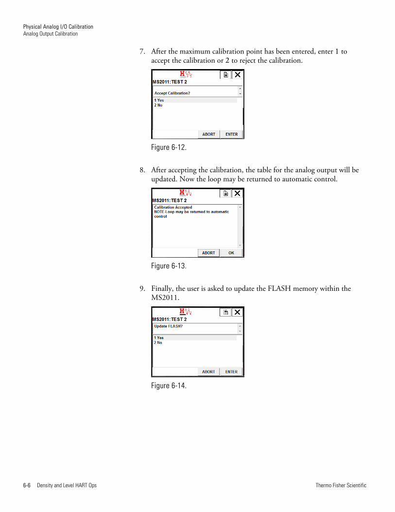
7. After the maximum calibration point has been entered, enter 1 to accept the calibration or 2 to reject the calibration.
Figure 6-12.
8. After accepting the calibration, the table for the analog output will be updated. Now the loop may be returned to automatic control.
Figure 6-13.
9. Finally, the user is asked to update the FLASH memory within the MS2011.
Figure 6-14.
Physical Analog I/O Calibration Analog Output Calibration
Thermo Fisher Scientific Density and Level HART Ops 6-7
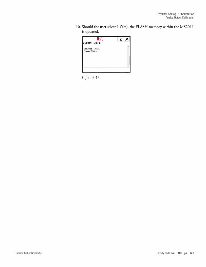
10. Should the user select 1 (Yes), the FLASH memory within the MS2011 is updated.
Figure 6-15.

Thermo Fisher Scientific Density and Level HART Ops 7-1
Chapter 7 Level Standardization & Calibration
This chapter provides instructions on how to use the 475 HHT DD methods and menus to standardize and calibrate the MS2011 for a level application.
Note For detailed discussion on standardization and calibration, reference the LevelPRO user guide, P/N 1-0702-039.
Note It is best practice to empty the tank and standardize during the initial setup process.
Follow the below procedure to perform standardization.
1. Empty the tank entirely, or to a level that is well below the bottom of both the source and detector.
2. Open the shutter(s).
Note The shutter(s) will need to be open and the vessel empty (maximum radiation on the detector) for at least 30 minutes prior to performing the standardization or calibration cycle. This wait time is necessary for proper orientation of the gauge.
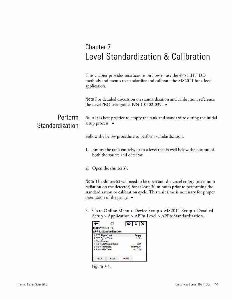
3. Go to Online Menu > Device Setup > MS2011 Setup > Detailed Setup > Application > APPn:Level > APPn:Standardization.
Figure 7-1.
Perform Standardization
Level Standardization & Calibration Perform Standardization
7-2 Density and Level HART Ops Thermo Fisher Scientific
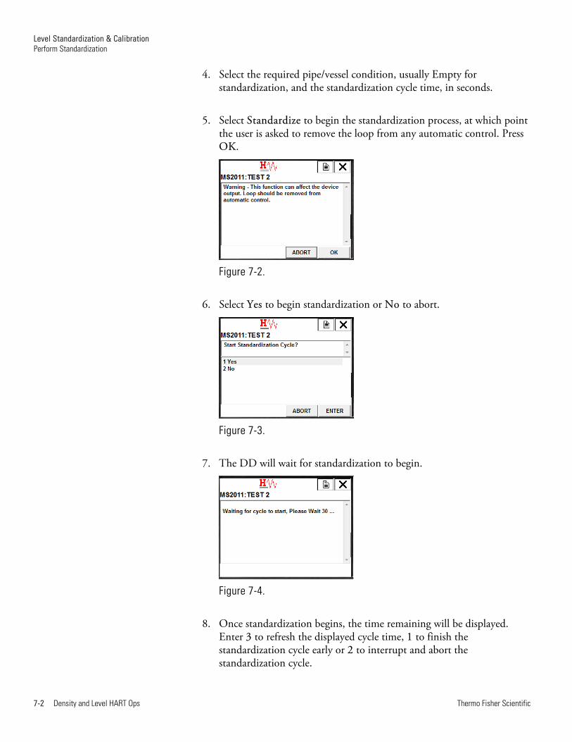
4. Select the required pipe/vessel condition, usually Empty for standardization, and the standardization cycle time, in seconds.
5. Select Standardize to begin the standardization process, at which point the user is asked to remove the loop from any automatic control. Press OK.
Figure 7-2.
6. Select Yes to begin standardization or No to abort.
Figure 7-3.
7. The DD will wait for standardization to begin.
Figure 7-4.
8. Once standardization begins, the time remaining will be displayed. Enter 3 to refresh the displayed cycle time, 1 to finish the standardization cycle early or 2 to interrupt and abort the standardization cycle.
Level Standardization & Calibration Perform Standardization
Thermo Fisher Scientific Density and Level HART Ops 7-3
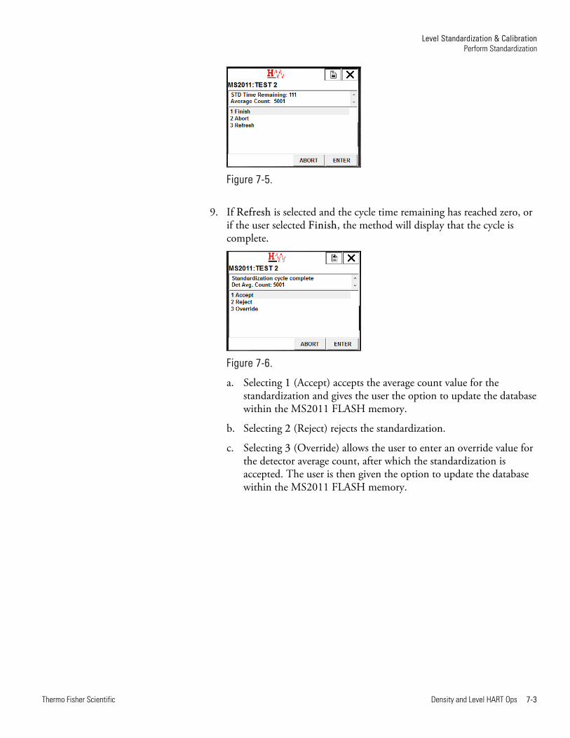
Figure 7-5.
9. If Refresh is selected and the cycle time remaining has reached zero, or if the user selected Finish, the method will display that the cycle is complete.
Figure 7-6.
a. Selecting 1 (Accept) accepts the average count value for the standardization and gives the user the option to update the database within the MS2011 FLASH memory.
b. Selecting 2 (Reject) rejects the standardization.
c. Selecting 3 (Override) allows the user to enter an override value for the detector average count, after which the standardization is accepted. The user is then given the option to update the database within the MS2011 FLASH memory.
Level Standardization & Calibration Perform Calibration
7-4 Density and Level HART Ops Thermo Fisher Scientific
Caution If you do not calibrate the gauge, some tanks might overflow without reaching the tank full level. This can occur if the radiation measured at the detector when the tank is full (process level at the top of the detector) is greater than the assumed background radiation. If your application requires accurate level measurements, perform a calibration.
Note It is a good idea to calibrate at the tank-full level first, then at several intermediate levels, especially where the tank or gauge geometry changes.
Follow these steps to perform a calibration.
1. If necessary, set up the gauge.
2. Standardize according to Perform Standardization.
3. Fill the tank with process material to the particular level of interest. Measure the level accurately and keep it as steady as possible.
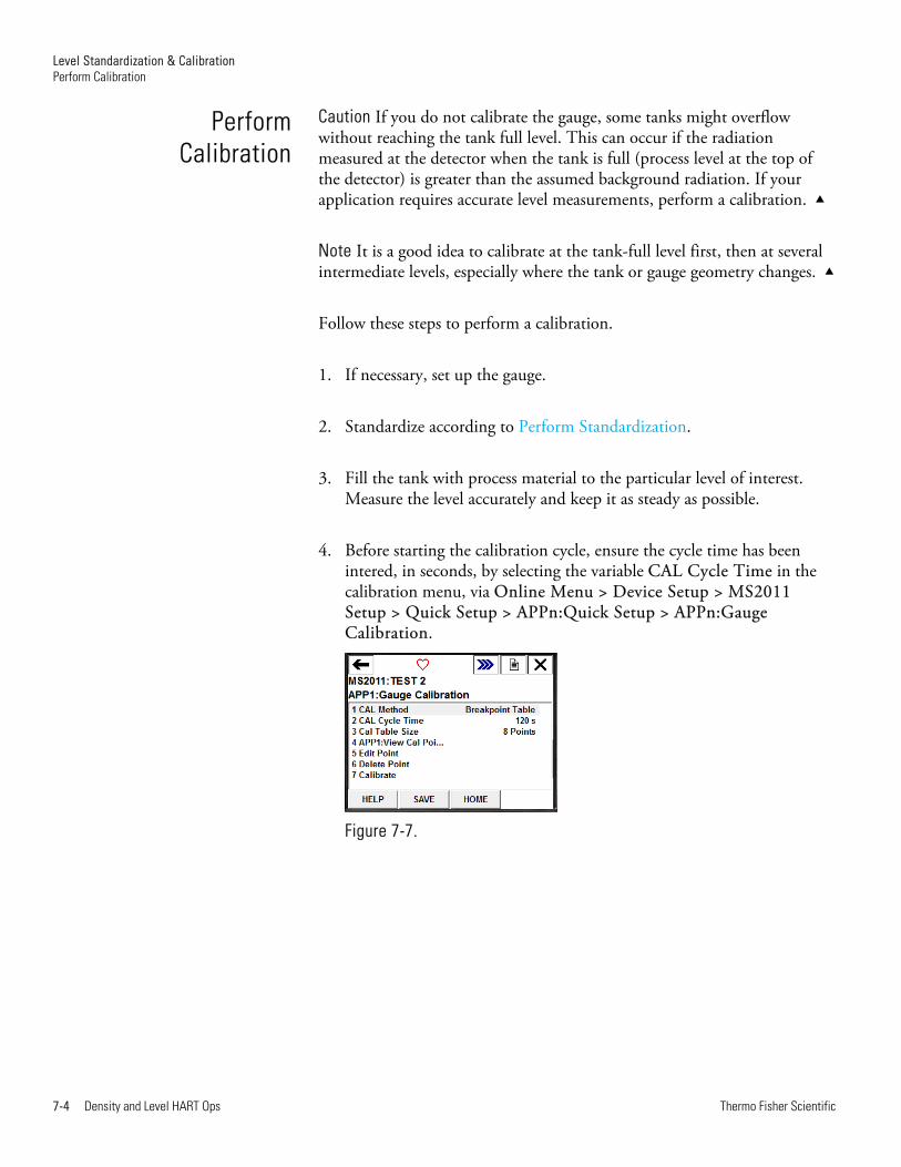
4. Before starting the calibration cycle, ensure the cycle time has been intered, in seconds, by selecting the variable CAL Cycle Time in the calibration menu, via Online Menu > Device Setup > MS2011 Setup > Quick Setup > APPn:Quick Setup > APPn:Gauge Calibration.
Figure 7-7.
Perform Calibration

Level Standardization & Calibration Perform Calibration
Thermo Fisher Scientific Density and Level HART Ops 7-5
5. Select Calibrate to start the calibration and press OK.
Figure 7-8.
6. Select the point to be calibrated. If no prior calibration has been performed, the first point will be calibrated. Should calibration points already exist in the calibration table, the user must select the last point in the list to calibrate a new point.
In the figure below, there are already eight points in the calibration table, so the ninth point is selected.
Figure 7-9.
7. Enter the level for the calibration point and press Enter.
Figure 7-10.
Level Standardization & Calibration Perform Calibration
7-6 Density and Level HART Ops Thermo Fisher Scientific
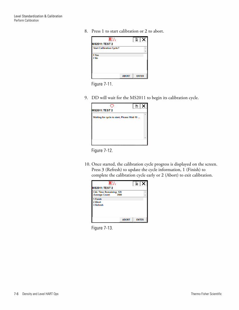
8. Press 1 to start calibration or 2 to abort.
Figure 7-11.
9. DD will wait for the MS2011 to begin its calibration cycle.
Figure 7-12.
10. Once started, the calibration cycle progress is displayed on the screen. Press 3 (Refresh) to update the cycle information, 1 (Finish) to complete the calibration cycle early or 2 (Abort) to exit calibration.
Figure 7-13.
Level Standardization & Calibration Perform Calibration
Thermo Fisher Scientific Density and Level HART Ops 7-7
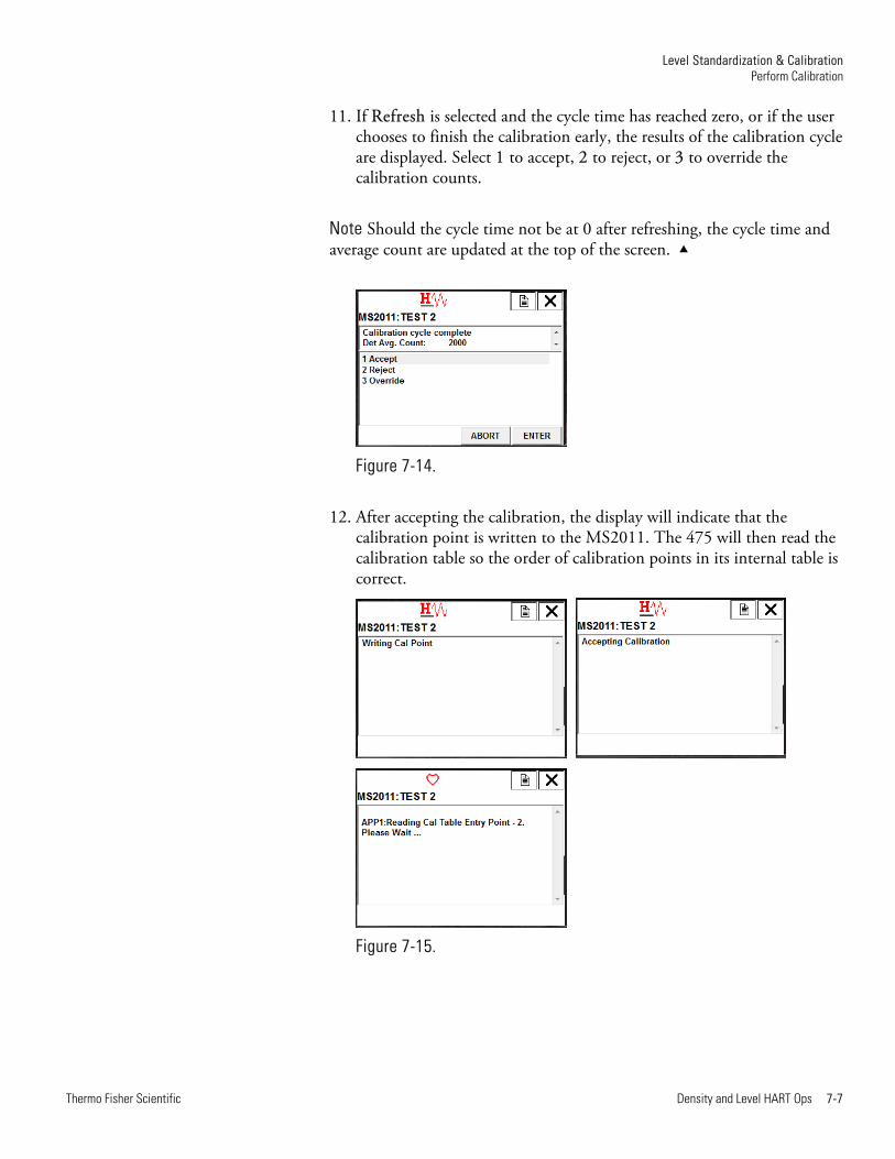
11. If Refresh is selected and the cycle time has reached zero, or if the user chooses to finish the calibration early, the results of the calibration cycle are displayed. Select 1 to accept, 2 to reject, or 3 to override the calibration counts.
Note Should the cycle time not be at 0 after refreshing, the cycle time and average count are updated at the top of the screen.
Figure 7-14.
12. After accepting the calibration, the display will indicate that the calibration point is written to the MS2011. The 475 will then read the calibration table so the order of calibration points in its internal table is correct.
Figure 7-15.
Level Standardization & Calibration Perform Calibration
7-8 Density and Level HART Ops Thermo Fisher Scientific
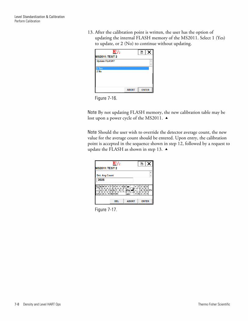
13. After the calibration point is written, the user has the option of updating the internal FLASH memory of the MS2011. Select 1 (Yes) to update, or 2 (No) to continue without updating.
Figure 7-16.
Note By not updating FLASH memory, the new calibration table may be lost upon a power cycle of the MS2011.
Note Should the user wish to override the detector average count, the new value for the average count should be entered. Upon entry, the calibration point is accepted in the sequence shown in step 12, followed by a request to update the FLASH as shown in step 13.
Figure 7-17.

Thermo Fisher Scientific Density and Level HART Ops 8-1
Chapter 8 Density Standardization & Calibration
This chapter provides instruction on how to use the 475 HHT DD methods and menus to standardize and calibrate the MS2011 for a density application.
Note For detailed discussion on standardization and calibration, reference the DensityPRO Measurement Systems user guide, P/N 1-0702-016.
Follow this procedure to perform standardization.
1. Put the gauge head and pipe in one of the following standard configurations. Use the same standard configuration during every standardization.
a. Pipe full of carrier
b. Pipe empty
c. Pipe full of process material
2. Open the source shutter.
3. From the Online Menu go to Device Setup > MS2011 Setup > Detailed Setup > Application > APPn:Density > APPn:Standardization.
Figure 8-1.
Perform Standardization

Density Standardization & Calibration Perform Standardization
8-2 Density and Level HART Ops Thermo Fisher Scientific
4. Confirm STD Pipe Condition is correct and enter the required standardization cycle time, in seconds.
5. Select Standardize, and, when prompted, remove the loop from automatic control.
6. Enter the standardization density in g/cc.
Figure 8-2.
7. Select 1 to start the standardization cycle or 2 to abort standardization.
Figure 8-3.
Density Standardization & Calibration Perform Standardization
Thermo Fisher Scientific Density and Level HART Ops 8-3
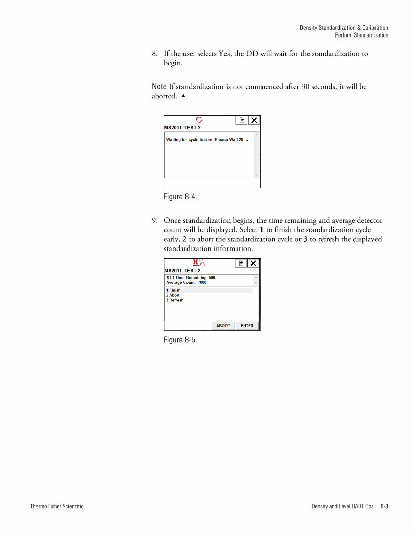
8. If the user selects Yes, the DD will wait for the standardization to begin.
Note If standardization is not commenced after 30 seconds, it will be aborted.
Figure 8-4.
9. Once standardization begins, the time remaining and average detector count will be displayed. Select 1 to finish the standardization cycle early, 2 to abort the standardization cycle or 3 to refresh the displayed standardization information.
Figure 8-5.

Density Standardization & Calibration Perform Standardization
8-4 Density and Level HART Ops Thermo Fisher Scientific
10. If, after selecting Refresh, the time remaining has reached zero, or if the user has selected Finish to end standardization early, the below screen will be displayed. Enter 1 to accept the displayed detector count, 2 to reject the detector count, or 3 to override the detector count with a user-entered value.
Figure 8-6.
11. After accepting the standardization, the standardization cycle will be accepted and written to the MS2011.
Figure 8-7.
12. In the event the user decides to override the Detector Average Count in step 10, a new value must be entered before the standardization cycle is accepted.
Figure 8-8.
Density Standardization & Calibration Perform Calibration
Thermo Fisher Scientific Density and Level HART Ops 8-5
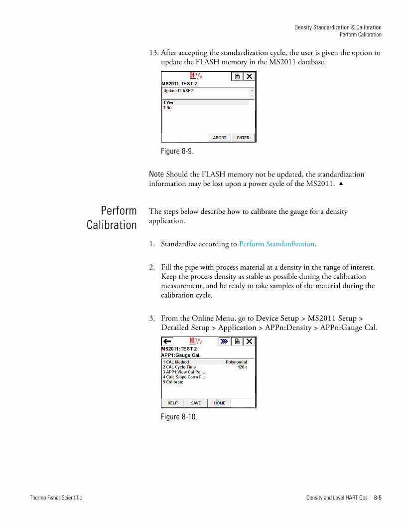
13. After accepting the standardization cycle, the user is given the option to update the FLASH memory in the MS2011 database.
Figure 8-9.
Note Should the FLASH memory not be updated, the standardization information may be lost upon a power cycle of the MS2011.
The steps below describe how to calibrate the gauge for a density application.
1. Standardize according to Perform Standardization.
2. Fill the pipe with process material at a density in the range of interest. Keep the process density as stable as possible during the calibration measurement, and be ready to take samples of the material during the calibration cycle.
3. From the Online Menu, go to Device Setup > MS2011 Setup > Detailed Setup > Application > APPn:Density > APPn:Gauge Cal.
Figure 8-10.
Perform Calibration
Density Standardization & Calibration Perform Calibration
8-6 Density and Level HART Ops Thermo Fisher Scientific
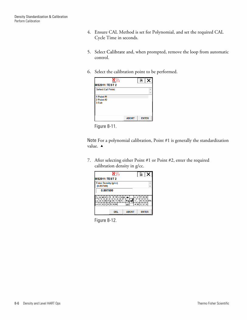
4. Ensure CAL Method is set for Polynomial, and set the required CAL Cycle Time in seconds.
5. Select Calibrate and, when prompted, remove the loop from automatic control.
6. Select the calibration point to be performed.
Figure 8-11.
Note For a polynomial calibration, Point #1 is generally the standardization value.
7. After selecting either Point #1 or Point #2, enter the required calibration density in g/cc.
Figure 8-12.
Density Standardization & Calibration Perform Calibration
Thermo Fisher Scientific Density and Level HART Ops 8-7
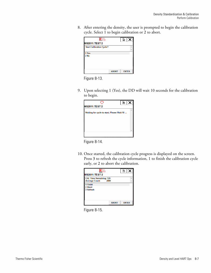
8. After entering the density, the user is prompted to begin the calibration cycle. Select 1 to begin calibration or 2 to abort.
Figure 8-13.
9. Upon selecting 1 (Yes), the DD will wait 10 seconds for the calibration to begin.
Figure 8-14.
10. Once started, the calibration cycle progress is displayed on the screen. Press 3 to refresh the cycle information, 1 to finish the calibration cycle early, or 2 to abort the calibration.
Figure 8-15.

Density Standardization & Calibration Perform Calibration
8-8 Density and Level HART Ops Thermo Fisher Scientific
11. If, after selecting Refresh, the time remaining has reached zero, or if the user has selected Finish to end calibration early, the results of the calibration cycle are displayed. Enter 1 to accept the calibration counts, 2 to reject the calibration counts, or 3 to override the calibration counts.
Note Should the cycle time not have reached zero when refreshed, the cycle time and average count are updated at the top of the screen.
Figure 8-16.
12. After accepting the calibration, the display will indicate that the calibration point is accepted and written to the MS2011.
Figure 8-17.
13. In the event the user decides to override the Detector Average Count in step 11, a new value must be entered before the calibration cycle is accepted.
Figure 8-18.

Density Standardization & Calibration Perform Calibration
Thermo Fisher Scientific Density and Level HART Ops 8-9
14. After the calibration point is written, the user is given the option of updating the internal FLASH memory in the MS2011. Select 1 to update the FLASH memory or 2 to continue without updating.
Figure 8-19.
Note By not updating the FLASH memory, the new calibration table may be lost upon a power cycle of the MS2011.

Thermo Fisher Scientific Density and Level HART Ops 9-1
Chapter 9 Menu Samples
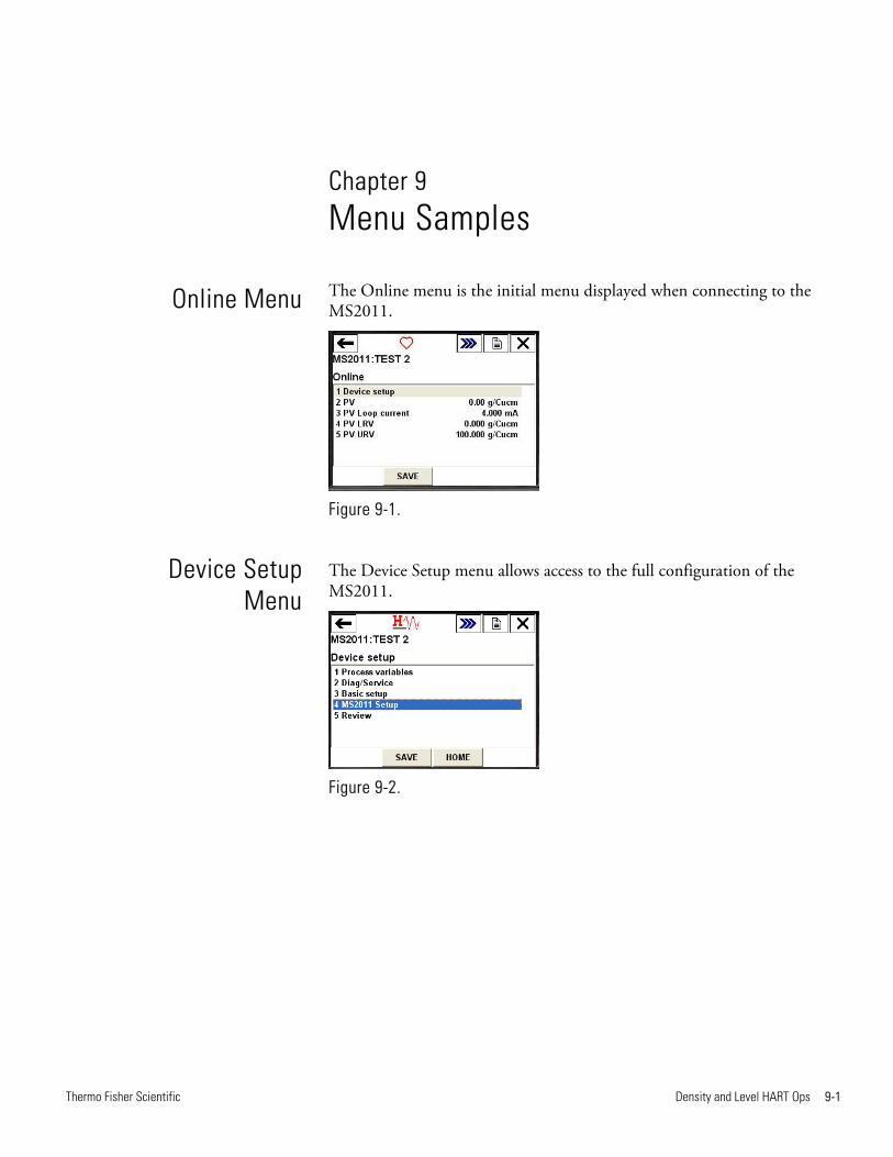
The Online menu is the initial menu displayed when connecting to the MS2011.
Figure 9-1.
The Device Setup menu allows access to the full configuration of the MS2011.
Figure 9-2.
Online Menu
Device SetupMenu
Menu Samples Process Variables Menu
9-2 Density and Level HART Ops Thermo Fisher Scientific
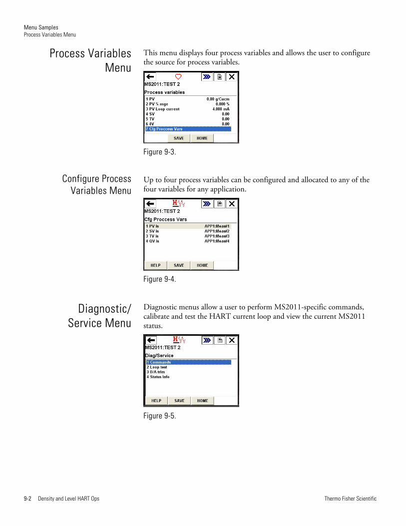
This menu displays four process variables and allows the user to configure the source for process variables.
Figure 9-3.
Up to four process variables can be configured and allocated to any of the four variables for any application.
Figure 9-4.
Diagnostic menus allow a user to perform MS2011-specific commands, calibrate and test the HART current loop and view the current MS2011 status.
Figure 9-5.
Process VariablesMenu
Configure Process Variables Menu
Diagnostic/Service Menu

Menu Samples Diagnostic/ Service Menu
Thermo Fisher Scientific Density and Level HART Ops 9-3
This method enables a user to perform specific commands to control the operation of the MS2011.
Figure 9-6.
This method allows a user to provide a fixed current output on the HART 4-20 mA current loop.
Figure 9-7.
Commands Method
Loop Test Method
Menu Samples Diagnostic/ Service Menu
9-4 Density and Level HART Ops Thermo Fisher Scientific
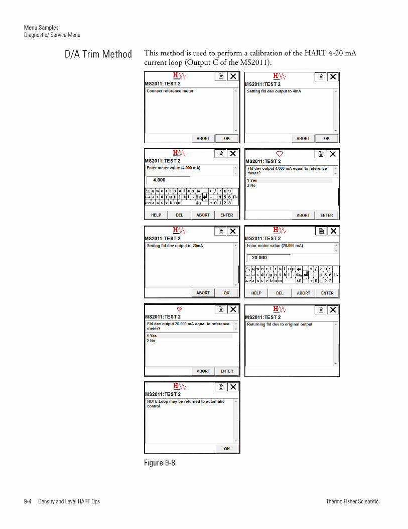
This method is used to perform a calibration of the HART 4-20 mA current loop (Output C of the MS2011).
Figure 9-8.
D/A Trim Method

Menu Samples Basic Setup Menu
Thermo Fisher Scientific Density and Level HART Ops 9-5
The Status Info menu is used to display the current status of the MS2011. A non-zero value indicates an alarm status is set. Selecting the status item will display the meaning of each of the bits within each byte.
Figure 9-9.
The Basic Setup menu is used to configure the basic HART information for the MS2011.
Figure 9-10.
The Range Values menu configures the primary variable upper and lower range values for the HART 4-20 mA current loop.
Figure 9-11.
Status Info Menu
Basic SetupMenu
Range Values Menu
Menu Samples Basic Setup Menu
9-6 Density and Level HART Ops Thermo Fisher Scientific
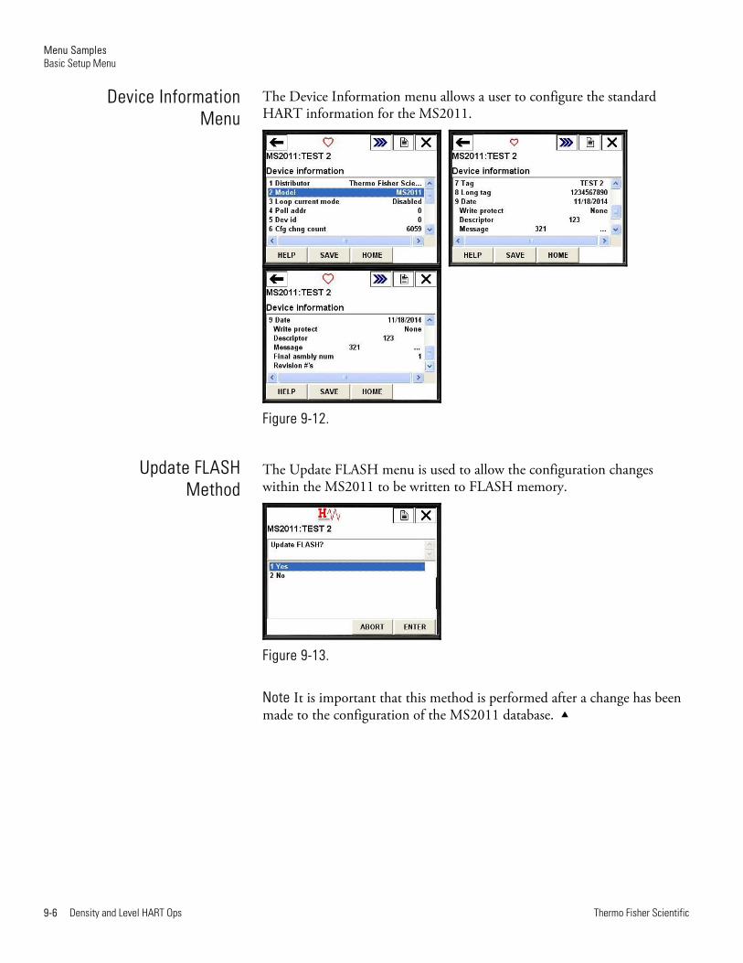
The Device Information menu allows a user to configure the standard HART information for the MS2011.
Figure 9-12.
The Update FLASH menu is used to allow the configuration changes within the MS2011 to be written to FLASH memory.
Figure 9-13.
Note It is important that this method is performed after a change has been made to the configuration of the MS2011 database.
Device InformationMenu
Update FLASHMethod

Menu Samples MS2011 Setup Menu
Thermo Fisher Scientific Density and Level HART Ops 9-7
The MS2011 Setup menu is used to access the full configuration of the device-specific configuration of the MS2011.
Figure 9-14.
The Application Setup menu configures up to four separate applications on the MS2011. Each application can be configured independently for either level or density measurement. Generally, an integrated unit will only have a single application configured.
Figure 9-15.
The Application 1 Setup menu allows the configuration of either a level or density application. Should a change be made to either the density type or oilfield units, the application’s configuration within the MS2011 will reset to a preset default condition.
Figure 9-16.
MS2011 SetupMenu
Application SetupMenu
App1:Setup Menu

Menu Samples MS2011 Setup Menu
9-8 Density and Level HART Ops Thermo Fisher Scientific
Note The setup screens for Applications 2, 3 and 4 are identical to Application 1, with the exception that the cascaded level option is only available on Application 1.
The below method should be used when initially configuring an application. The method will step the user through the stages of setting up the application.
Figure 9-17.
The Detector Map menu shows the available detectors present on the MS2011. For an integrated MS2011, only detector 1 will be present.
Figure 9-18.
Modify Application
Det Map

Menu Samples MS2011 Setup Menu
Thermo Fisher Scientific Density and Level HART Ops 9-9
This menu allows access to the measurement and totals for an application.
Figure 9-19.
Note Totals are not available for a level application, and so will not be available in the Live Data menu.
The Measurements menu shows the live values for each of the configured menus for the application. Up to four measurements can be configured, so a maximum of four application measurements may be displayed.
Figure 9-20.
The four totalizers available for each density application are displayed on this menu.
Figure 9-21.
Note Totals are not available for level applications.
Live Data Menu
Measurements Menu
Totals Menu
Menu Samples MS2011 Setup Menu
9-10 Density and Level HART Ops Thermo Fisher Scientific
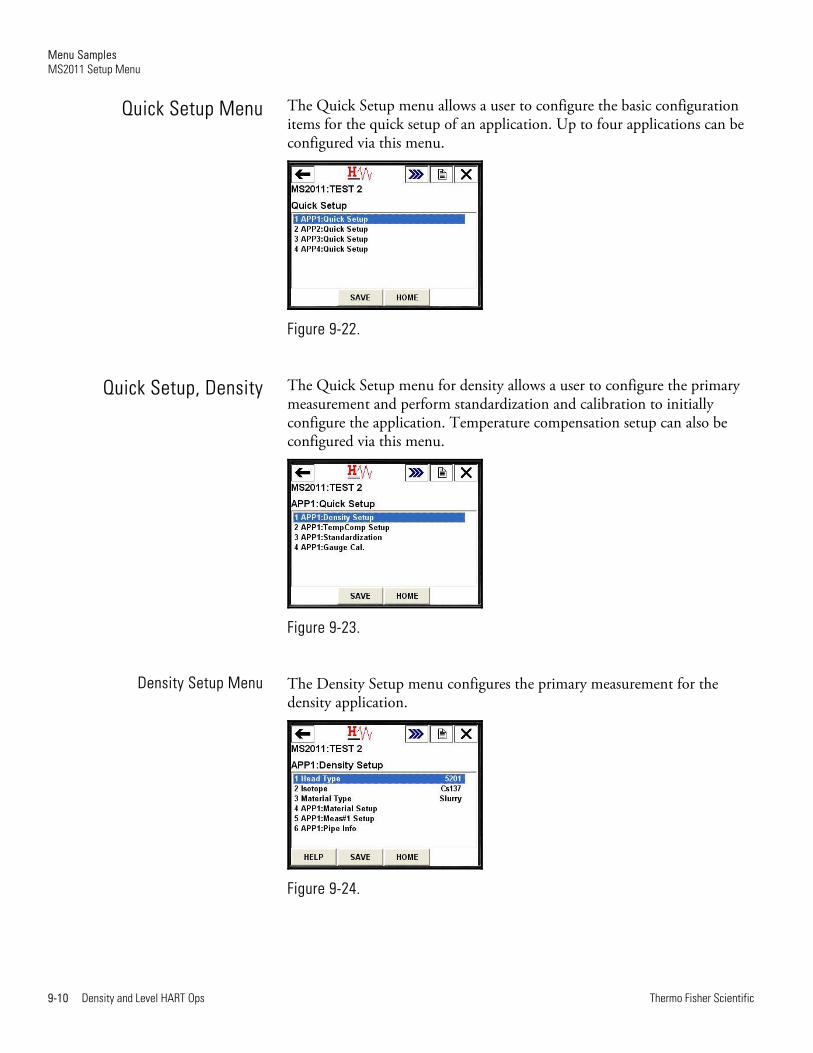
The Quick Setup menu allows a user to configure the basic configuration items for the quick setup of an application. Up to four applications can be configured via this menu.
Figure 9-22.
The Quick Setup menu for density allows a user to configure the primary measurement and perform standardization and calibration to initially configure the application. Temperature compensation setup can also be configured via this menu.
Figure 9-23.
The Density Setup menu configures the primary measurement for the density application.
Figure 9-24.
Quick Setup Menu
Quick Setup, Density
Density Setup Menu
Menu Samples MS2011 Setup Menu
Thermo Fisher Scientific Density and Level HART Ops 9-11
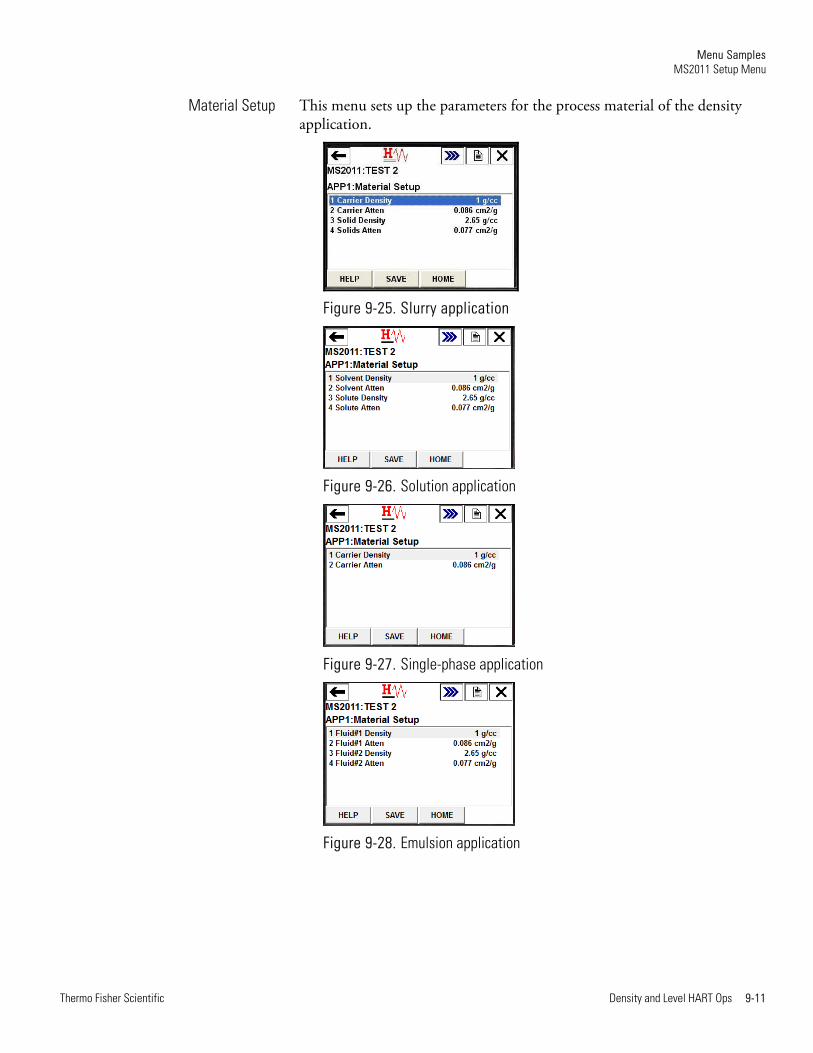
This menu sets up the parameters for the process material of the density application.
Figure 9-25. Slurry application
Figure 9-26. Solution application
Figure 9-27. Single-phase application
Figure 9-28. Emulsion application
Material Setup

Menu Samples MS2011 Setup Menu
9-12 Density and Level HART Ops Thermo Fisher Scientific
The Meas#1 Setup menu defines the variable type, units and displayed decimal places for the primary measurement of the density application.
Figure 9-29.
The Pipe Info menu configures the pipe information for the application.
Figure 9-30.
The Temperature Compensation Setup menu allows users to setup the various parameters for the temperature-compensated density calculation. Up to two polynomial compensation curves can be configured via this menu.
Figure 9-31.
Meas#1 Setup Menu
Pipe Info Menu
TempComp Setup Menu
Menu Samples MS2011 Setup Menu
Thermo Fisher Scientific Density and Level HART Ops 9-13
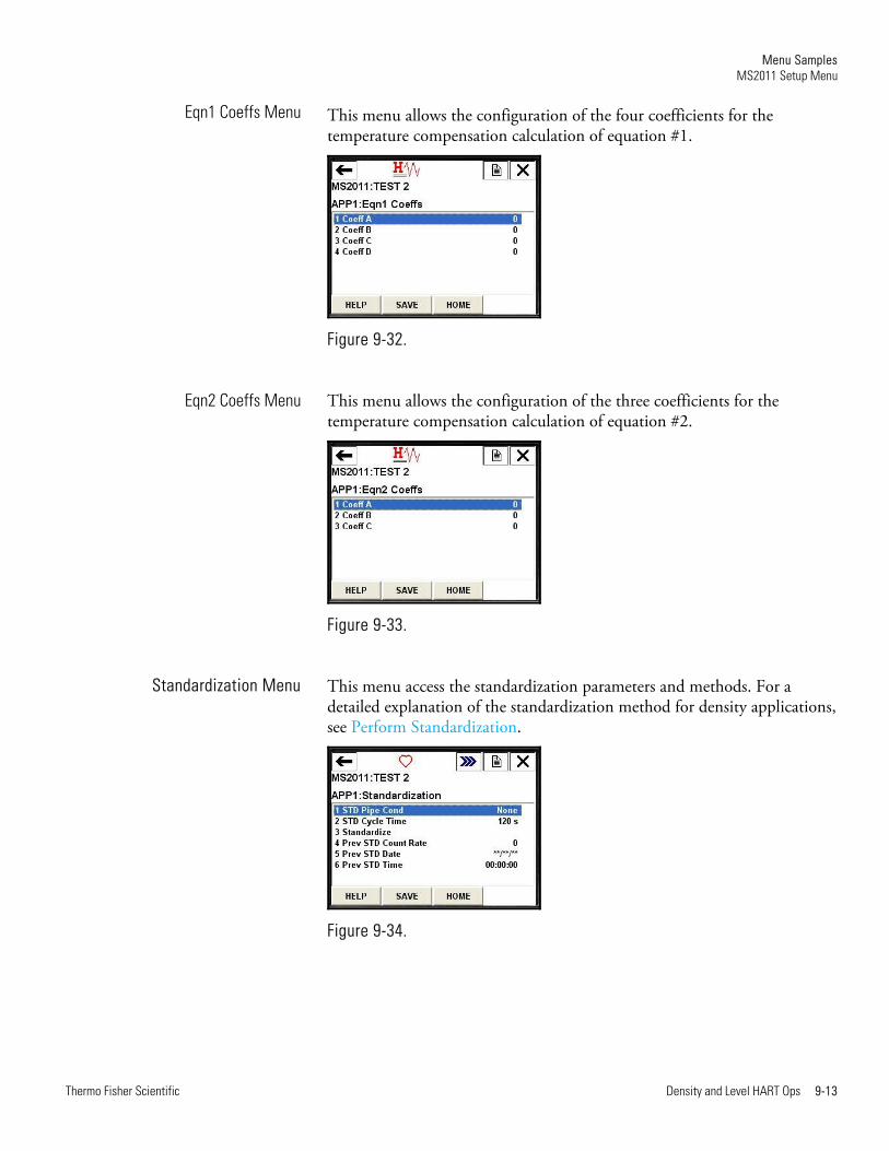
This menu allows the configuration of the four coefficients for the temperature compensation calculation of equation #1.
Figure 9-32.
This menu allows the configuration of the three coefficients for the temperature compensation calculation of equation #2.
Figure 9-33.
This menu access the standardization parameters and methods. For a detailed explanation of the standardization method for density applications, see Perform Standardization.
Figure 9-34.
Eqn1 Coeffs Menu
Eqn2 Coeffs Menu
Standardization Menu

Menu Samples MS2011 Setup Menu
9-14 Density and Level HART Ops Thermo Fisher Scientific
This menu access the calibration parameters and methods. For a detailed explanation of the calibration method for density applications, see Perform Calibration.
Figure 9-35.
The View Cal Points menu allows the user to view information on the two polynomial calibration points for the density application.
Figure 9-36.
The slope correction method can be used to recalculate the slope correction factor for the calibration table, should a value within the table be modified manually.
Figure 9-37.
Gauge Calibration Menu
View Cal Points Menu
Calc Slope Corrn Factor
Menu Samples MS2011 Setup Menu
Thermo Fisher Scientific Density and Level HART Ops 9-15
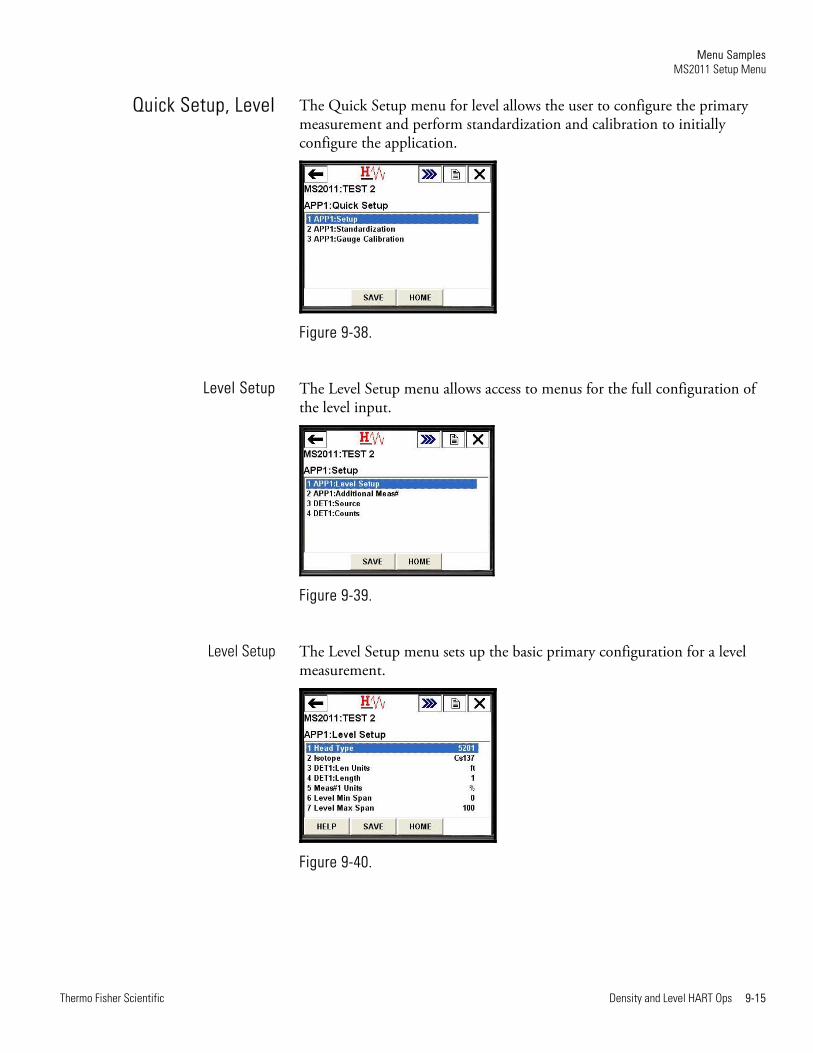
The Quick Setup menu for level allows the user to configure the primary measurement and perform standardization and calibration to initially configure the application.
Figure 9-38.
The Level Setup menu allows access to menus for the full configuration of the level input.
Figure 9-39.
The Level Setup menu sets up the basic primary configuration for a level measurement.
Figure 9-40.
Quick Setup, Level
Level Setup
Level Setup
Menu Samples MS2011 Setup Menu
9-16 Density and Level HART Ops Thermo Fisher Scientific
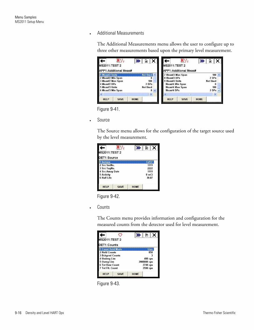
Additional Measurements
The Additional Measurements menu allows the user to configure up to three other measurements based upon the primary level measurement.
Figure 9-41.
Source
The Source menu allows for the configuration of the target source used by the level measurement.
Figure 9-42.
Counts
The Counts menu provides information and configuration for the measured counts from the detector used for level measurement.
Figure 9-43.
Menu Samples MS2011 Setup Menu
Thermo Fisher Scientific Density and Level HART Ops 9-17
This menu accesses the standardization parameters and methods. For a detailed explanation of the standardization method for level applications, see Perform Standardization.
Figure 9-44.
This menu accesses the calibration parameters and methods. For a detailed explanation of the calibration method for level applications, see Perform Calibration.
Figure 9-45.
The Veiw Cal Points menu is used to view up to 10 breakpoint table entries for the level application.
Figure 9-46.
Standardization Menu
Gauge Calibration
View Cal Points
Menu Samples MS2011 Setup Menu
9-18 Density and Level HART Ops Thermo Fisher Scientific
The Edit Point method is used to modify a selected calibration point within the breakpoint table.
Figure 9-47.
The Delete Point method is used to remove a selected calibration point within the breakpoint table.
Figure 9-48.
For a detailed explanation of level calibration, refer to Perform Calibration.
Figure 9-49.
Edit Point
Delete Point
Calibrate
Menu Samples MS2011 Setup Menu
Thermo Fisher Scientific Density and Level HART Ops 9-19
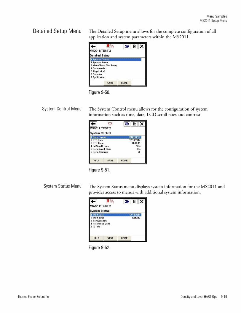
The Detailed Setup menu allows for the complete configuration of all application and system parameters within the MS2011.
Figure 9-50.
The System Control menu allows for the configuration of system information such as time, date, LCD scroll rates and contrast.
Figure 9-51.
The System Status menu displays system information for the MS2011 and provides access to menus with additional system information.
Figure 9-52.
Detailed Setup Menu
System Control Menu
System Status Menu
Menu Samples MS2011 Setup Menu
9-20 Density and Level HART Ops Thermo Fisher Scientific
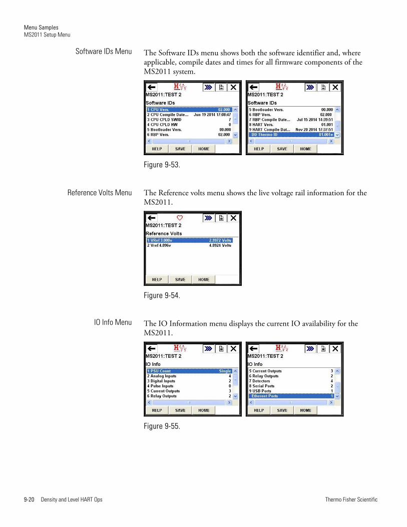
The Software IDs menu shows both the software identifier and, where applicable, compile dates and times for all firmware components of the MS2011 system.
Figure 9-53.
The Reference volts menu shows the live voltage rail information for the MS2011.
Figure 9-54.
The IO Information menu displays the current IO availability for the MS2011.
Figure 9-55.
Software IDs Menu
Reference Volts Menu
IO Info Menu

Menu Samples MS2011 Setup Menu
Thermo Fisher Scientific Density and Level HART Ops 9-21
The Mode/Fault Alarm Setup menu allows the user to configure output, application and system alarms.
Figure 9-56.
Mode/Fault Alarm SetupMenu
Menu Samples MS2011 Setup Menu
9-22 Density and Level HART Ops Thermo Fisher Scientific
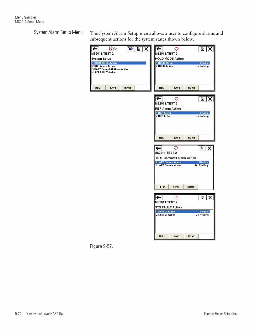
The System Alarm Setup menu allows a user to configure alarms and subsequent actions for the system states shown below.
Figure 9-57.
System Alarm Setup Menu

Menu Samples MS2011 Setup Menu
Thermo Fisher Scientific Density and Level HART Ops 9-23
The Output A Faults Setup menu allows the user to configure alarms and subsequent actions for the Analog Output A alarms shown below.
Figure 9-58.
Output A Faults Setup Menu
Menu Samples MS2011 Setup Menu
9-24 Density and Level HART Ops Thermo Fisher Scientific
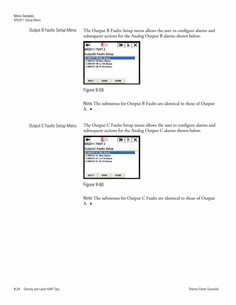
The Output B Faults Setup menu allows the user to configure alarms and subsequent actions for the Analog Output B alarms shown below.
Figure 9-59.
Note The submenus for Output B Faults are identical to those of Output A.
The Output C Faults Setup menu allows the user to configure alarms and subsequent actions for the Analog Output C alarms shown below.
Figure 9-60.
Note The submenus for Output C Faults are identical to those of Output A.
Output B Faults Setup Menu
Output C Faults Setup Menu
Menu Samples MS2011 Setup Menu
Thermo Fisher Scientific Density and Level HART Ops 9-25
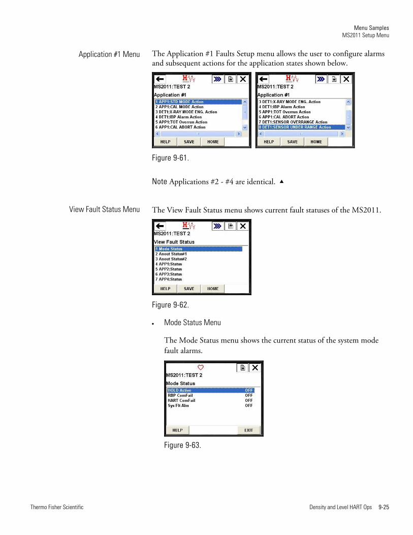
The Application #1 Faults Setup menu allows the user to configure alarms and subsequent actions for the application states shown below.
Figure 9-61.
Note Applications #2 - #4 are identical.
The View Fault Status menu shows current fault statuses of the MS2011.
Figure 9-62.
Mode Status Menu
The Mode Status menu shows the current status of the system mode fault alarms.
Figure 9-63.
Application #1 Menu
View Fault Status Menu
Menu Samples MS2011 Setup Menu
9-26 Density and Level HART Ops Thermo Fisher Scientific
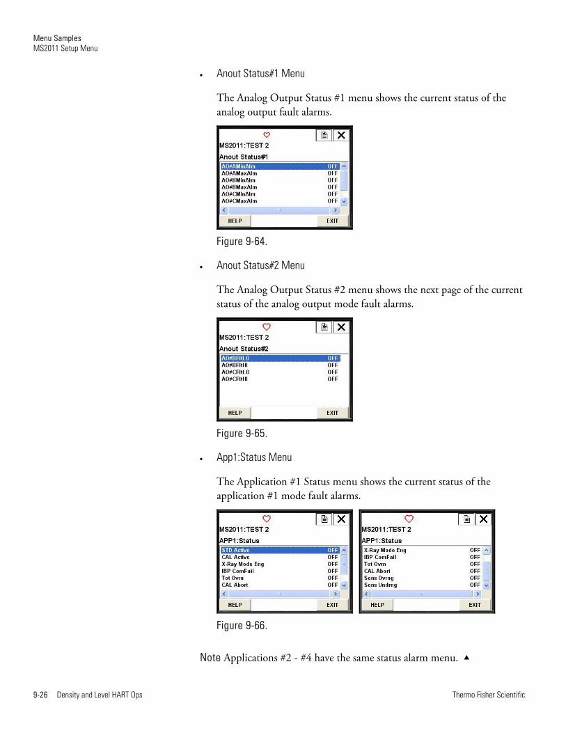
Anout Status#1 Menu
The Analog Output Status #1 menu shows the current status of the analog output fault alarms.
Figure 9-64.
Anout Status#2 Menu
The Analog Output Status #2 menu shows the next page of the current status of the analog output mode fault alarms.
Figure 9-65.
App1:Status Menu
The Application #1 Status menu shows the current status of the application #1 mode fault alarms.
Figure 9-66.
Note Applications #2 - #4 have the same status alarm menu.
Menu Samples MS2011 Setup Menu
Thermo Fisher Scientific Density and Level HART Ops 9-27
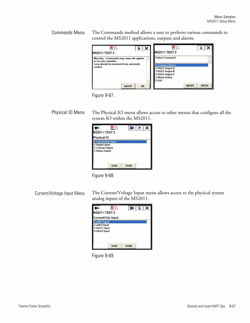
The Commands method allows a user to perform various commands to control the MS2011 applications, outputs and alarms.
Figure 9-67.
The Physical IO menu allows access to other menus that configure all the system IO within the MS2011.
Figure 9-68.
The Current/Voltage Input menu allows access to the physical system analog inputs of the MS2011.
Figure 9-69.
Commands Menu
Physical IO Menu
Current/Voltage Input Menu
Menu Samples MS2011 Setup Menu
9-28 Density and Level HART Ops Thermo Fisher Scientific
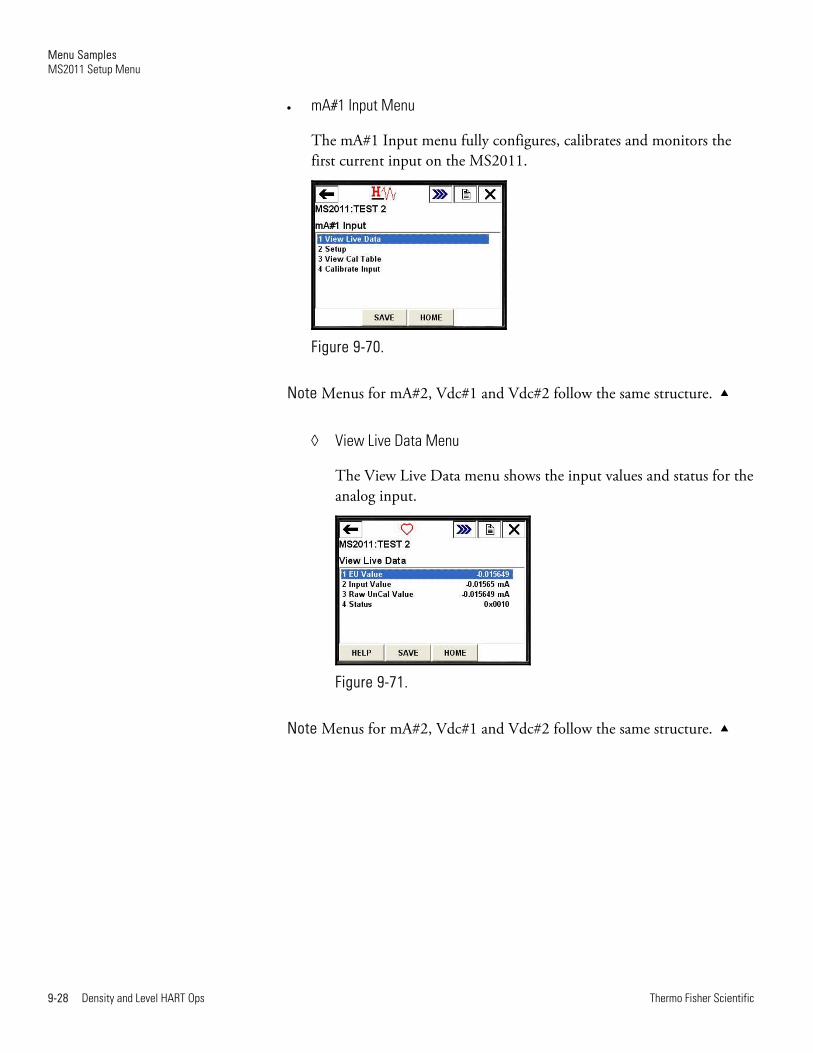
mA#1 Input Menu
The mA#1 Input menu fully configures, calibrates and monitors the first current input on the MS2011.
Figure 9-70.
Note Menus for mA#2, Vdc#1 and Vdc#2 follow the same structure.
View Live Data Menu
The View Live Data menu shows the input values and status for the analog input.
Figure 9-71.
Note Menus for mA#2, Vdc#1 and Vdc#2 follow the same structure.
Menu Samples MS2011 Setup Menu
Thermo Fisher Scientific Density and Level HART Ops 9-29
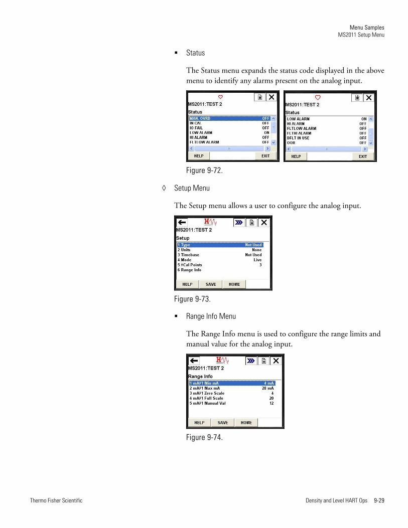
Status
The Status menu expands the status code displayed in the above menu to identify any alarms present on the analog input.
Figure 9-72.
Setup Menu
The Setup menu allows a user to configure the analog input.
Figure 9-73.
Range Info Menu
The Range Info menu is used to configure the range limits and manual value for the analog input.
Figure 9-74.
Menu Samples MS2011 Setup Menu
9-30 Density and Level HART Ops Thermo Fisher Scientific
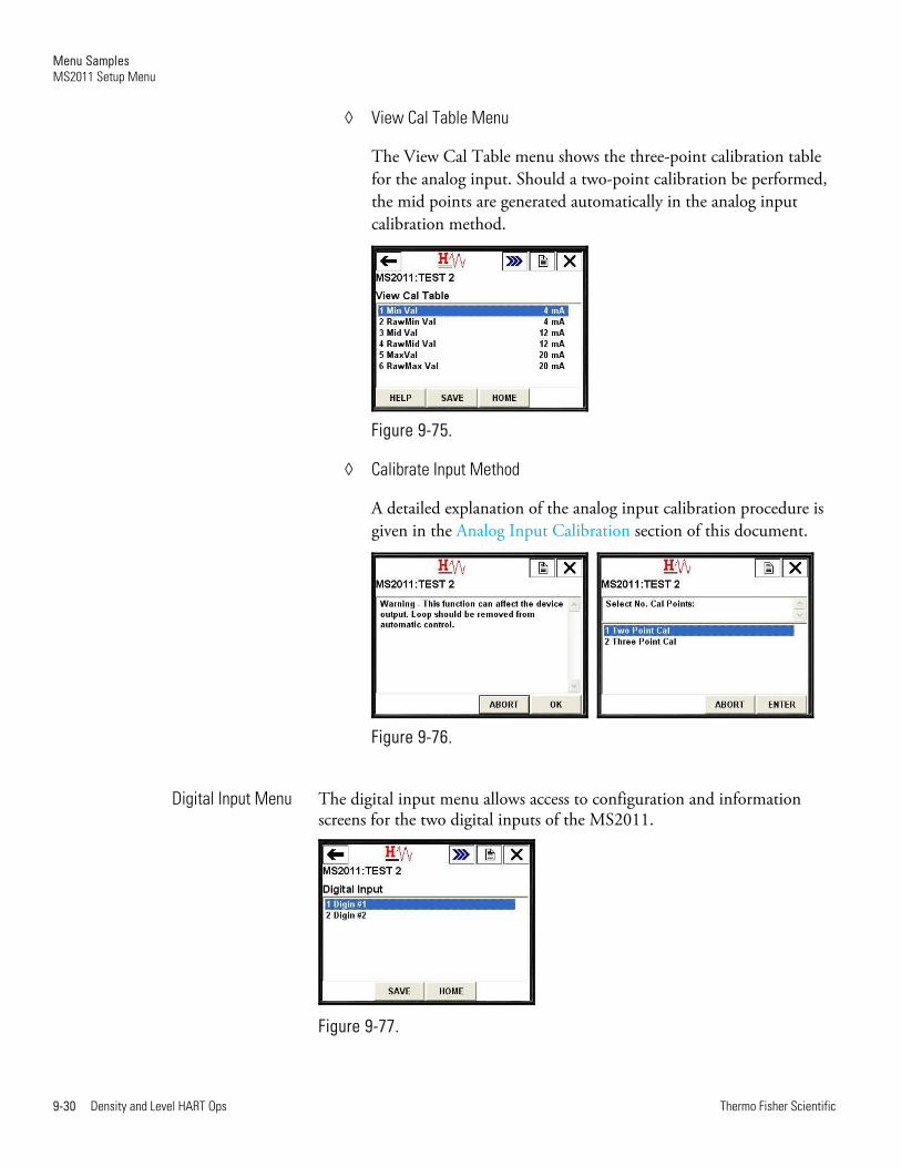
View Cal Table Menu
The View Cal Table menu shows the three-point calibration table for the analog input. Should a two-point calibration be performed, the mid points are generated automatically in the analog input calibration method.
Figure 9-75.
Calibrate Input Method
A detailed explanation of the analog input calibration procedure is given in the Analog Input Calibration section of this document.
Figure 9-76.
The digital input menu allows access to configuration and information screens for the two digital inputs of the MS2011.
Figure 9-77.
Digital Input Menu
Menu Samples MS2011 Setup Menu
Thermo Fisher Scientific Density and Level HART Ops 9-31
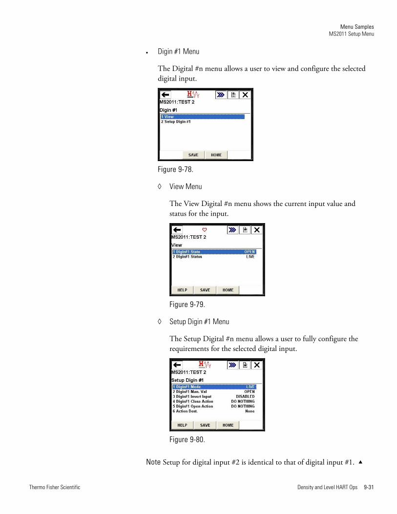
Digin #1 Menu
The Digital #n menu allows a user to view and configure the selected digital input.
Figure 9-78.
View Menu
The View Digital #n menu shows the current input value and status for the input.
Figure 9-79.
Setup Digin #1 Menu
The Setup Digital #n menu allows a user to fully configure the requirements for the selected digital input.
Figure 9-80.
Note Setup for digital input #2 is identical to that of digital input #1.

Menu Samples MS2011 Setup Menu
9-32 Density and Level HART Ops Thermo Fisher Scientific
The current output menu allows access to the configuration and information menus for each of the three analog outputs of the MS2011.
Figure 9-81.
Current Output A Menu
The Current Output #n menu allows the user to view, set up, calibrate and test the selected current output.
Figure 9-82.
View Live Data Menu
The View Live Data menu shows the current live information and status for the selected analog output.
Figure 9-83.
Current Output Menu
Menu Samples MS2011 Setup Menu
Thermo Fisher Scientific Density and Level HART Ops 9-33
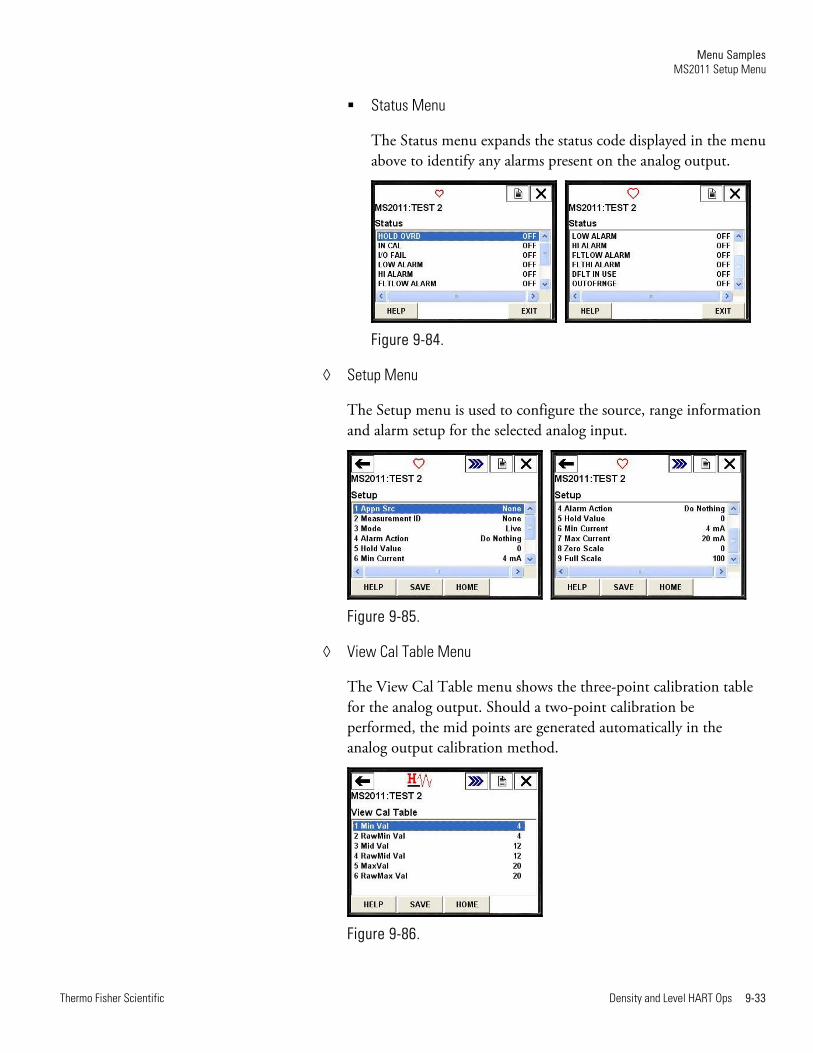
Status Menu
The Status menu expands the status code displayed in the menu above to identify any alarms present on the analog output.
Figure 9-84.
Setup Menu
The Setup menu is used to configure the source, range information and alarm setup for the selected analog input.
Figure 9-85.
View Cal Table Menu
The View Cal Table menu shows the three-point calibration table for the analog output. Should a two-point calibration be performed, the mid points are generated automatically in the analog output calibration method.
Figure 9-86.
Menu Samples MS2011 Setup Menu
9-34 Density and Level HART Ops Thermo Fisher Scientific
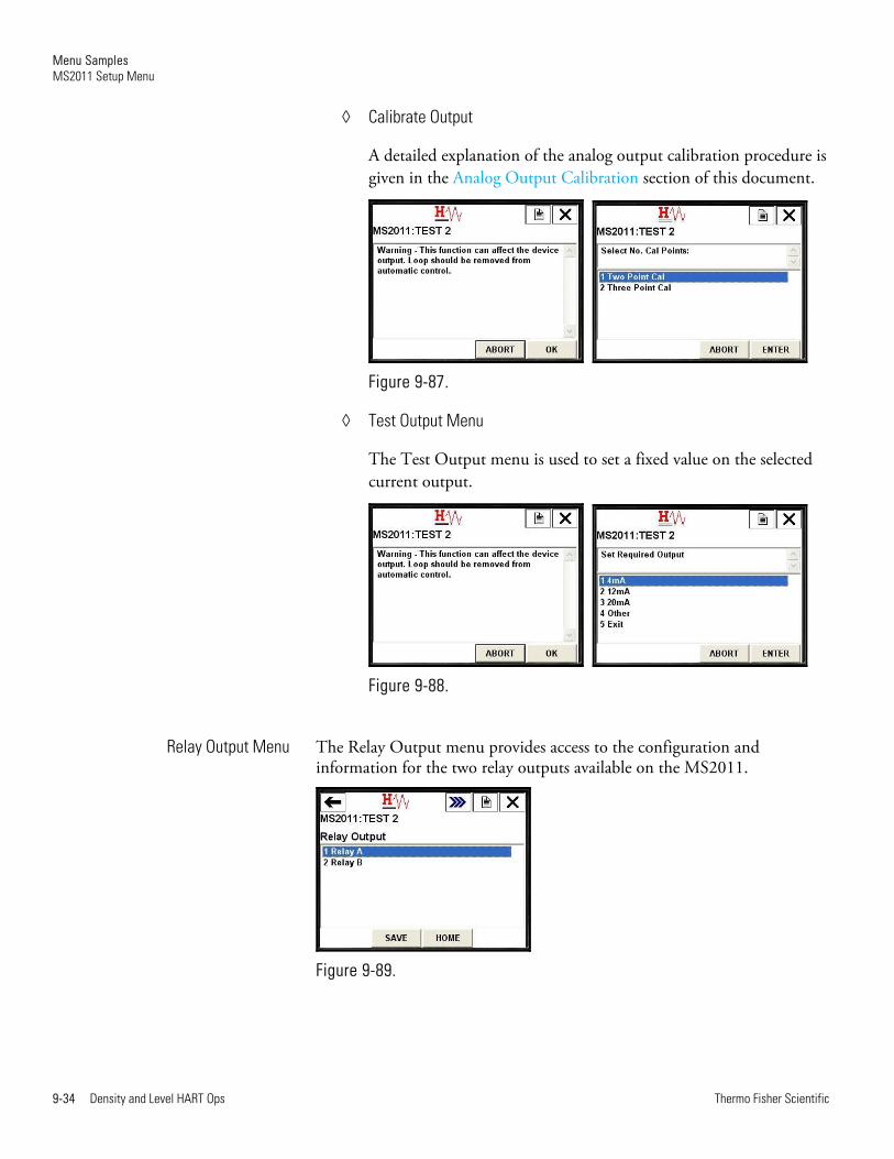
Calibrate Output
A detailed explanation of the analog output calibration procedure is given in the Analog Output Calibration section of this document.
Figure 9-87.
Test Output Menu
The Test Output menu is used to set a fixed value on the selected current output.
Figure 9-88.
The Relay Output menu provides access to the configuration and information for the two relay outputs available on the MS2011.
Figure 9-89.
Relay Output Menu
Menu Samples MS2011 Setup Menu
Thermo Fisher Scientific Density and Level HART Ops 9-35
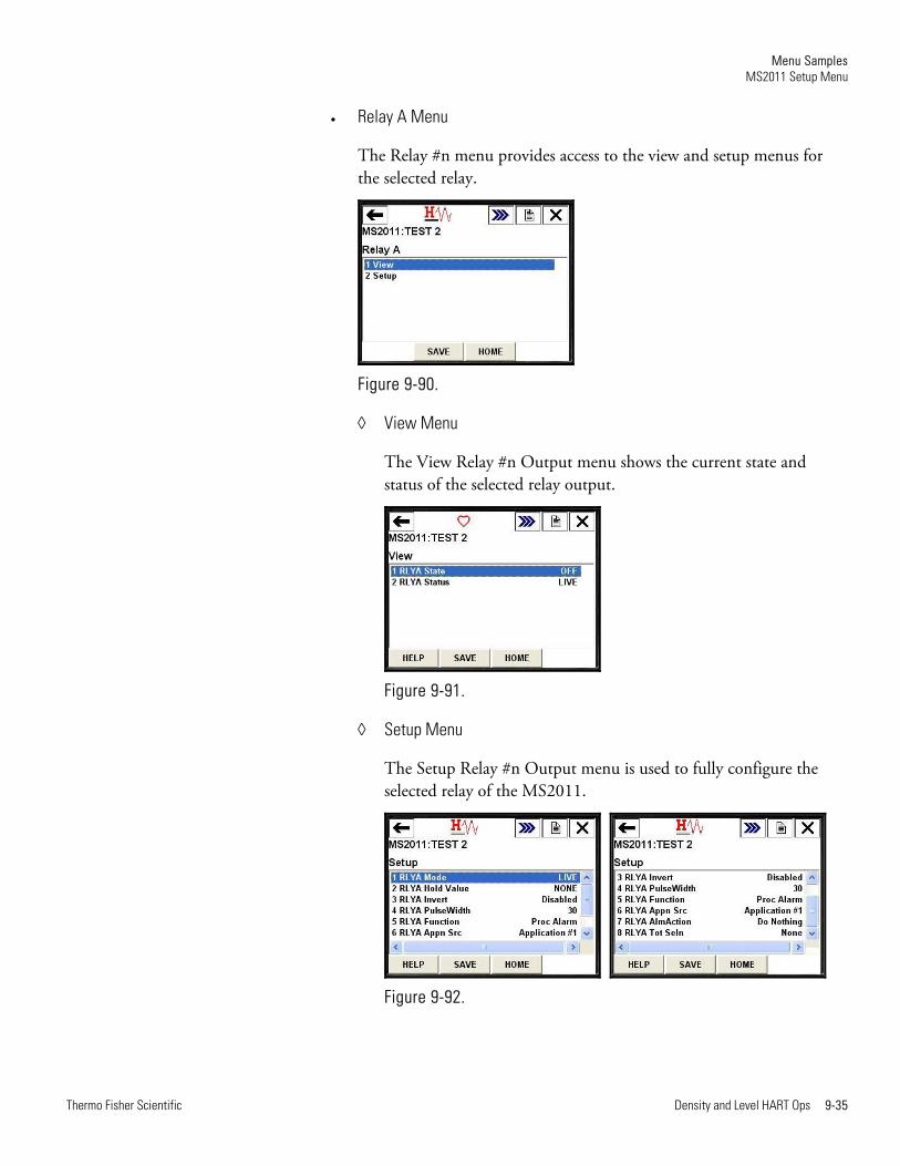
Relay A Menu
The Relay #n menu provides access to the view and setup menus for the selected relay.
Figure 9-90.
View Menu
The View Relay #n Output menu shows the current state and status of the selected relay output.
Figure 9-91.
Setup Menu
The Setup Relay #n Output menu is used to fully configure the selected relay of the MS2011.
Figure 9-92.
Menu Samples MS2011 Setup Menu
9-36 Density and Level HART Ops Thermo Fisher Scientific
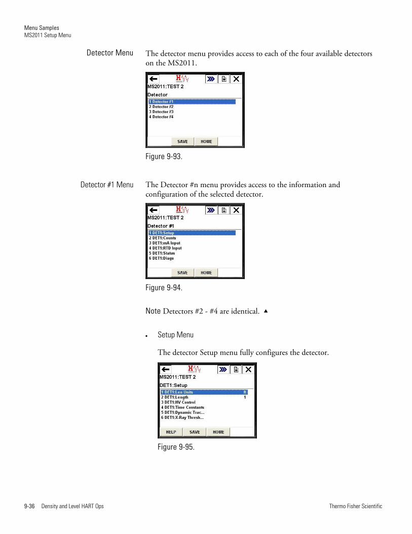
The detector menu provides access to each of the four available detectors on the MS2011.
Figure 9-93.
The Detector #n menu provides access to the information and configuration of the selected detector.
Figure 9-94.
Note Detectors #2 - #4 are identical.
Setup Menu
The detector Setup menu fully configures the detector.
Figure 9-95.
Detector Menu
Detector #1 Menu
Menu Samples MS2011 Setup Menu
Thermo Fisher Scientific Density and Level HART Ops 9-37
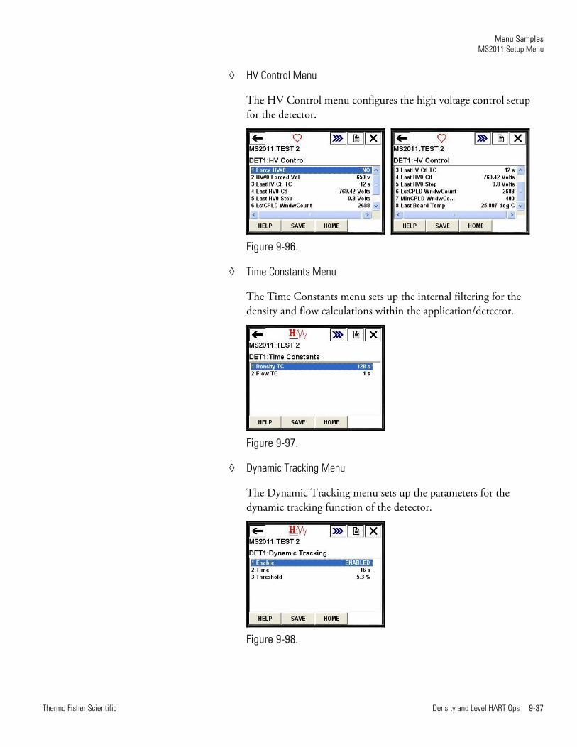
HV Control Menu
The HV Control menu configures the high voltage control setup for the detector.
Figure 9-96.
Time Constants Menu
The Time Constants menu sets up the internal filtering for the density and flow calculations within the application/detector.
Figure 9-97.
Dynamic Tracking Menu
The Dynamic Tracking menu sets up the parameters for the dynamic tracking function of the detector.
Figure 9-98.
Menu Samples MS2011 Setup Menu
9-38 Density and Level HART Ops Thermo Fisher Scientific
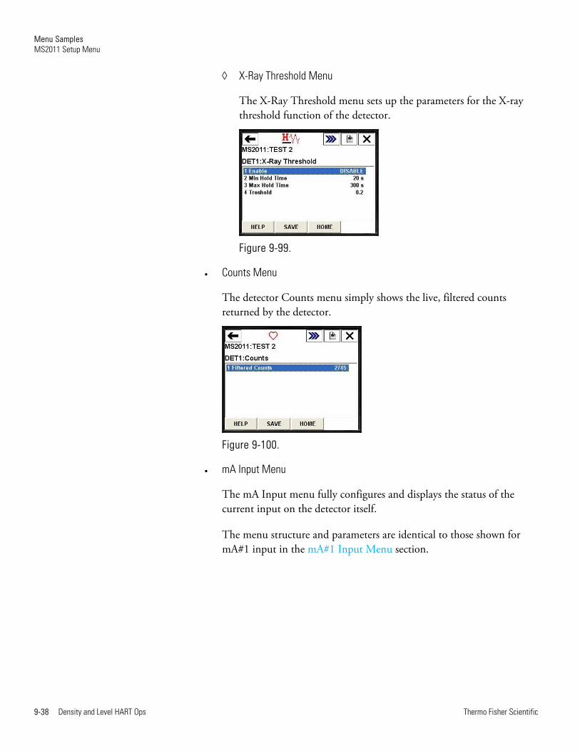
X-Ray Threshold Menu
The X-Ray Threshold menu sets up the parameters for the X-ray threshold function of the detector.
Figure 9-99.
Counts Menu
The detector Counts menu simply shows the live, filtered counts returned by the detector.
Figure 9-100.
mA Input Menu
The mA Input menu fully configures and displays the status of the current input on the detector itself.
The menu structure and parameters are identical to those shown for mA#1 input in the mA#1 Input Menu section.

Menu Samples MS2011 Setup Menu
Thermo Fisher Scientific Density and Level HART Ops 9-39
RTD Input Menu
The RTD Input menu fully configures and displays the status of the RTD input on the detector itself.
The menu structure and parameters are similar to those shown for input mA#1, with two exceptions. In the RTD Input menu, the user must select the RTD Type, and, in the Range Info menu, only the minimum and maximum range values are available.
Figure 9-101.
Status Menu
This Status menu provides access to the status menus for the selected detector.
Figure 9-102.
Menu Samples MS2011 Setup Menu
9-40 Density and Level HART Ops Thermo Fisher Scientific
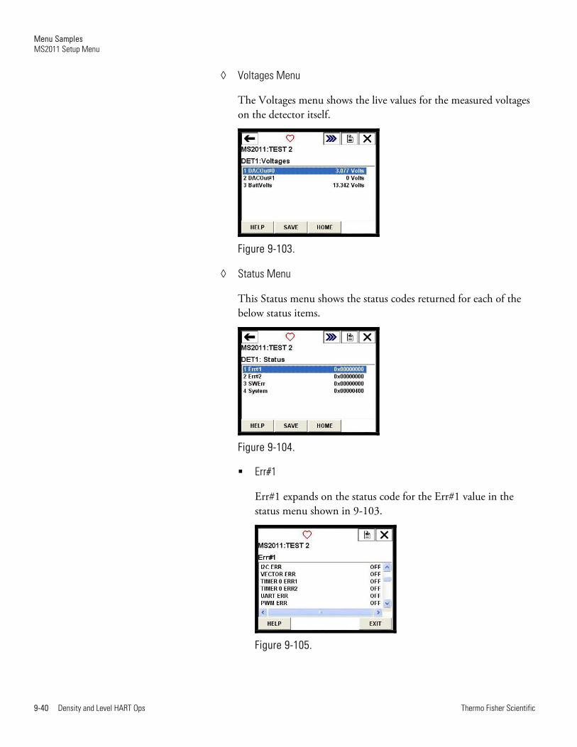
Voltages Menu
The Voltages menu shows the live values for the measured voltages on the detector itself.
Figure 9-103.
Status Menu
This Status menu shows the status codes returned for each of the below status items.
Figure 9-104.
Err#1
Err#1 expands on the status code for the Err#1 value in the status menu shown in 9-103.
Figure 9-105.
Menu Samples MS2011 Setup Menu
Thermo Fisher Scientific Density and Level HART Ops 9-41
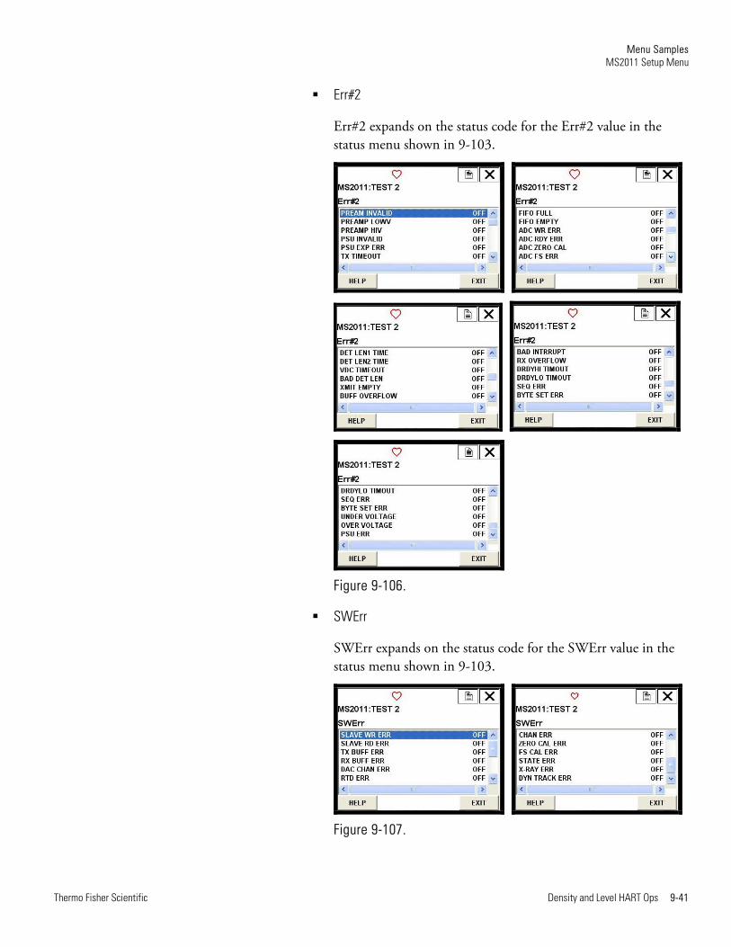
Err#2
Err#2 expands on the status code for the Err#2 value in the status menu shown in 9-103.
Figure 9-106.
SWErr
SWErr expands on the status code for the SWErr value in the status menu shown in 9-103.
Figure 9-107.

Menu Samples MS2011 Setup Menu
9-42 Density and Level HART Ops Thermo Fisher Scientific
System
System expands on the status code for the System value in the status menu shown in 9-103.
Figure 9-108.
Other Info Menu
The Other Info menu provides additional information for the selected detector.
Figure 9-109.
Menu Samples MS2011 Setup Menu
Thermo Fisher Scientific Density and Level HART Ops 9-43
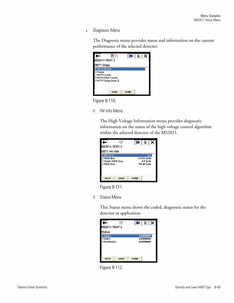
Diagnosis Menu
The Diagnosis menu provides status and information on the current performance of the selected detector.
Figure 9-110.
HV Info Menu
The High Voltage Information menu provides diagnostic information on the status of the high voltage control algorithm within the selected detector of the MS2011.
Figure 9-111.
Status Menu
This Status menu shows the coded, diagnostic status for the detector or application.
Figure 9-112.
Menu Samples MS2011 Setup Menu
9-44 Density and Level HART Ops Thermo Fisher Scientific
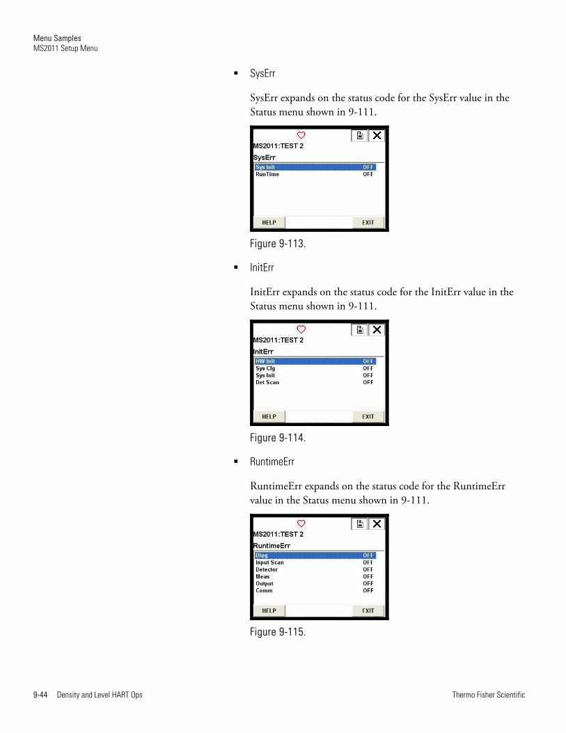
SysErr
SysErr expands on the status code for the SysErr value in the Status menu shown in 9-111.
Figure 9-113.
InitErr
InitErr expands on the status code for the InitErr value in the Status menu shown in 9-111.
Figure 9-114.
RuntimeErr
RuntimeErr expands on the status code for the RuntimeErr value in the Status menu shown in 9-111.
Figure 9-115.

Menu Samples MS2011 Setup Menu
Thermo Fisher Scientific Density and Level HART Ops 9-45
Counts Menu
The Counts menu shows the counter information for the selected detector.
Figure 9-116.
CPLD Counts Menu
The CPLD Counts menu shows the count information for the selected detector.
Figure 9-117.
Temperatures Menu
The Temperatures menu shows the diagnostic temperature information for the selected detector.
Figure 9-118.
Menu Samples MS2011 Setup Menu
9-46 Density and Level HART Ops Thermo Fisher Scientific
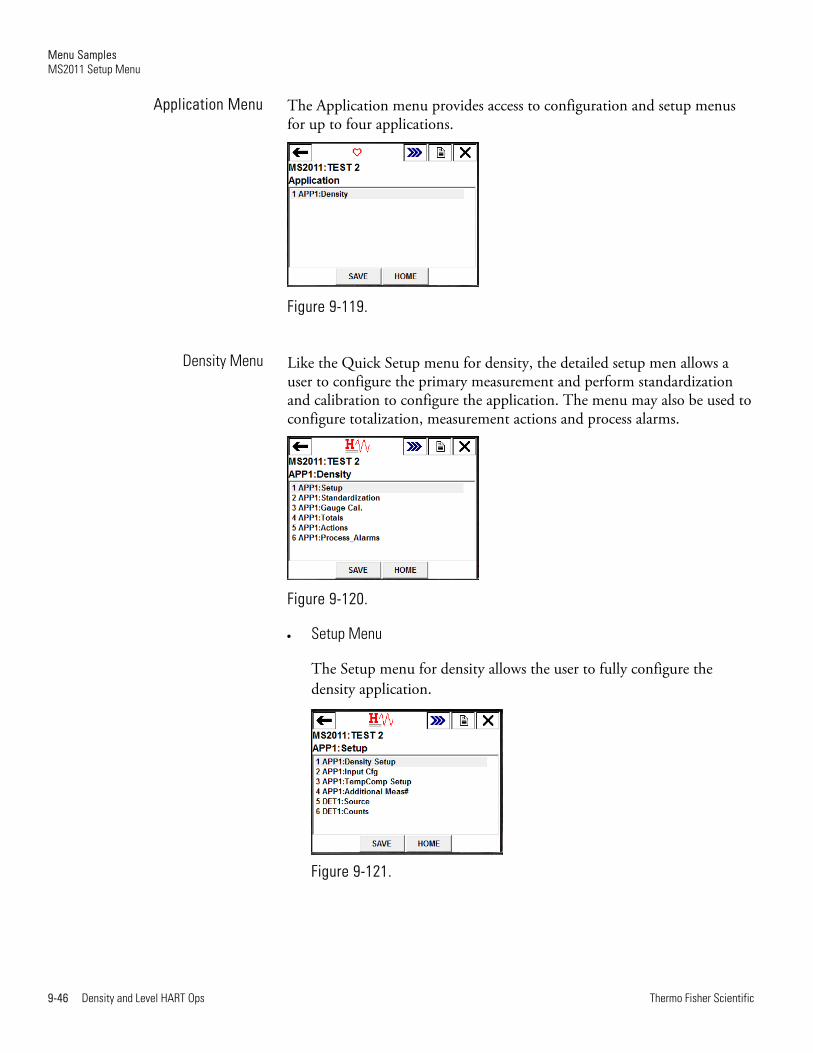
The Application menu provides access to configuration and setup menus for up to four applications.
Figure 9-119.
Like the Quick Setup menu for density, the detailed setup men allows a user to configure the primary measurement and perform standardization and calibration to configure the application. The menu may also be used to configure totalization, measurement actions and process alarms.
Figure 9-120.
Setup Menu
The Setup menu for density allows the user to fully configure the density application.
Figure 9-121.
Application Menu
Density Menu
Menu Samples MS2011 Setup Menu
Thermo Fisher Scientific Density and Level HART Ops 9-47
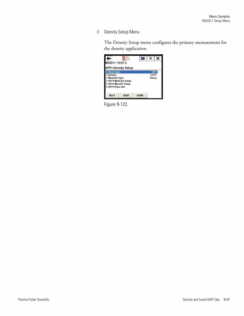
Density Setup Menu
The Density Setup menu configures the primary measurement for the density application.
Figure 9-122.

Menu Samples MS2011 Setup Menu
9-48 Density and Level HART Ops Thermo Fisher Scientific
Material Setup Menu
This menu sets up the parameters for the process material for the density application.
Figure 9-123. Slurry application
Figure 9-124. Solution application
Figure 9-125. Single-phase application
Figure 9-126. Emulsion application
Menu Samples MS2011 Setup Menu
Thermo Fisher Scientific Density and Level HART Ops 9-49
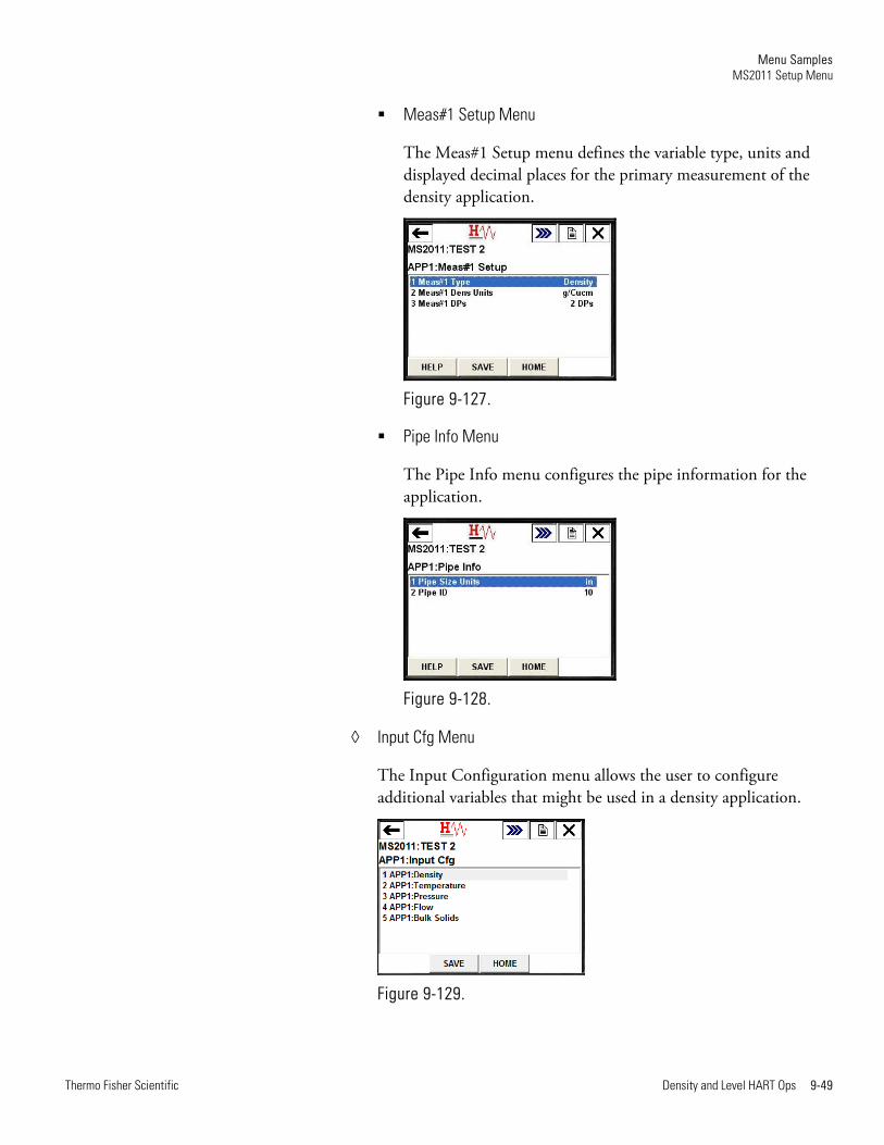
Meas#1 Setup Menu
The Meas#1 Setup menu defines the variable type, units and displayed decimal places for the primary measurement of the density application.
Figure 9-127.
Pipe Info Menu
The Pipe Info menu configures the pipe information for the application.
Figure 9-128.
Input Cfg Menu
The Input Configuration menu allows the user to configure additional variables that might be used in a density application.
Figure 9-129.
Menu Samples MS2011 Setup Menu
9-50 Density and Level HART Ops Thermo Fisher Scientific
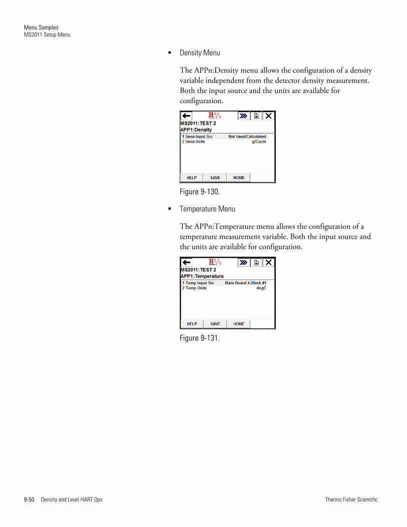
Density Menu
The APPn:Density menu allows the configuration of a density variable independent from the detector density measurement. Both the input source and the units are available for configuration.
Figure 9-130.
Temperature Menu
The APPn:Temperature menu allows the configuration of a temperature measurement variable. Both the input source and the units are available for configuration.
Figure 9-131.
Menu Samples MS2011 Setup Menu
Thermo Fisher Scientific Density and Level HART Ops 9-51
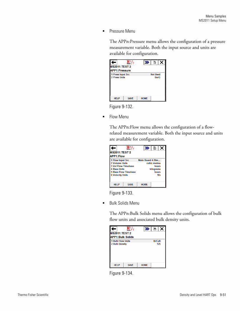
Pressure Menu
The APPn:Pressure menu allows the configuration of a pressure measurement variable. Both the input source and units are available for configuration.
Figure 9-132.
Flow Menu
The APPn:Flow menu allows the configuration of a flow-related measurement variable. Both the input source and units are available for configuration.
Figure 9-133.
Bulk Solids Menu
The APPn:Bulk Solids menu allows the configuration of bulk flow units and associated bulk density units.
Figure 9-134.
Menu Samples MS2011 Setup Menu
9-52 Density and Level HART Ops Thermo Fisher Scientific
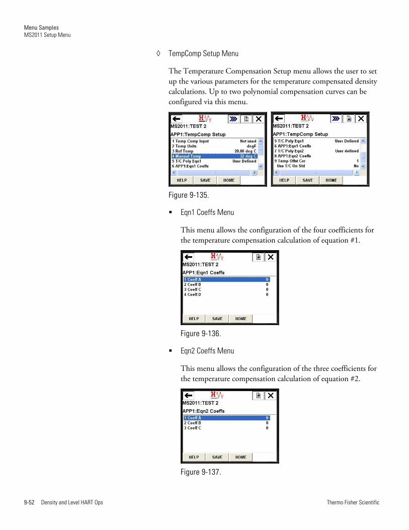
TempComp Setup Menu
The Temperature Compensation Setup menu allows the user to set up the various parameters for the temperature compensated density calculations. Up to two polynomial compensation curves can be configured via this menu.
Figure 9-135.
Eqn1 Coeffs Menu
This menu allows the configuration of the four coefficients for the temperature compensation calculation of equation #1.
Figure 9-136.
Eqn2 Coeffs Menu
This menu allows the configuration of the three coefficients for the temperature compensation calculation of equation #2.
Figure 9-137.
Menu Samples MS2011 Setup Menu
Thermo Fisher Scientific Density and Level HART Ops 9-53
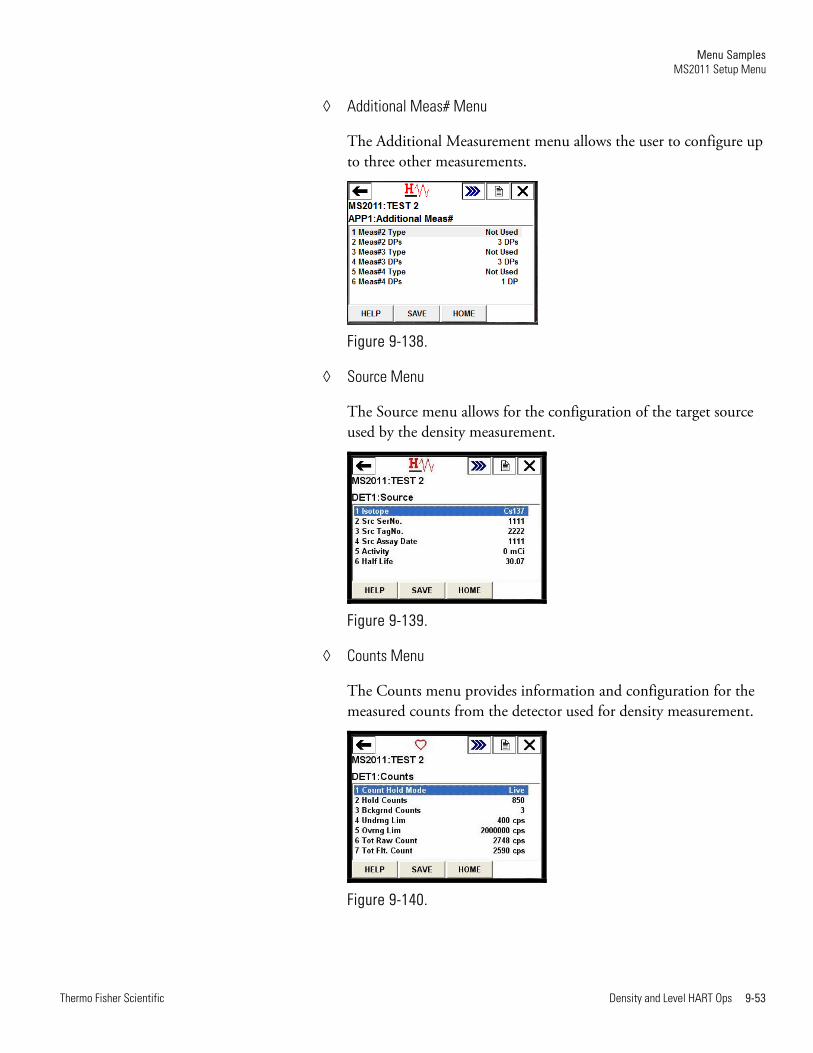
Additional Meas# Menu
The Additional Measurement menu allows the user to configure up to three other measurements.
Figure 9-138.
Source Menu
The Source menu allows for the configuration of the target source used by the density measurement.
Figure 9-139.
Counts Menu
The Counts menu provides information and configuration for the measured counts from the detector used for density measurement.
Figure 9-140.
Menu Samples MS2011 Setup Menu
9-54 Density and Level HART Ops Thermo Fisher Scientific
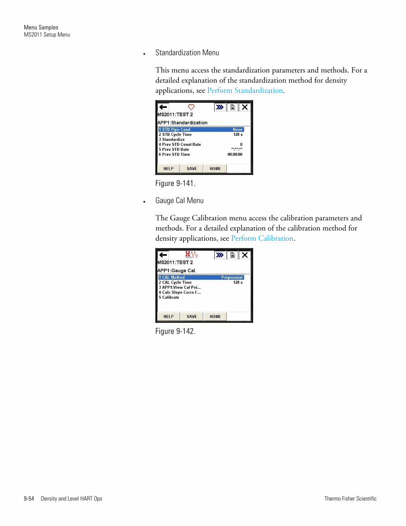
Standardization Menu
This menu access the standardization parameters and methods. For a detailed explanation of the standardization method for density applications, see Perform Standardization.
Figure 9-141.
Gauge Cal Menu
The Gauge Calibration menu access the calibration parameters and methods. For a detailed explanation of the calibration method for density applications, see Perform Calibration.
Figure 9-142.
Menu Samples MS2011 Setup Menu
Thermo Fisher Scientific Density and Level HART Ops 9-55
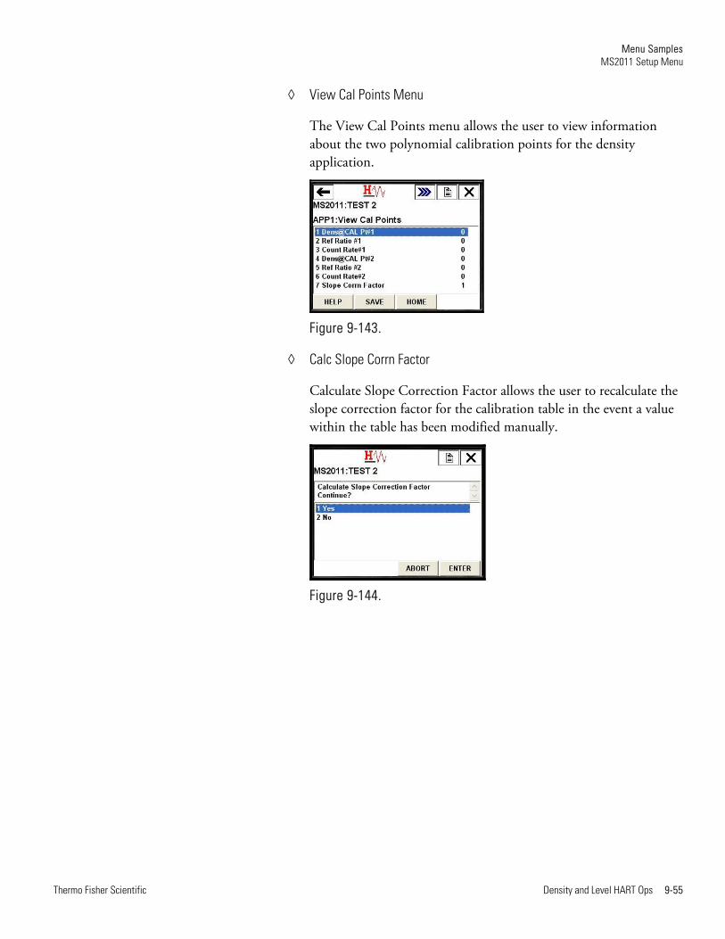
View Cal Points Menu
The View Cal Points menu allows the user to view information about the two polynomial calibration points for the density application.
Figure 9-143.
Calc Slope Corrn Factor
Calculate Slope Correction Factor allows the user to recalculate the slope correction factor for the calibration table in the event a value within the table has been modified manually.
Figure 9-144.

Menu Samples MS2011 Setup Menu
9-56 Density and Level HART Ops Thermo Fisher Scientific
Totals Menu
The Totals menu allows access to the configuration menus for up to four totalizers. A global configuration to enable/disable all totalizers is also available on this menu.
Figure 9-145.
Tot#1 Setup
Tot#n Setup allows the user to configure the source and set up the selected totalizer.
Figure 9-146.
Menu Samples MS2011 Setup Menu
Thermo Fisher Scientific Density and Level HART Ops 9-57
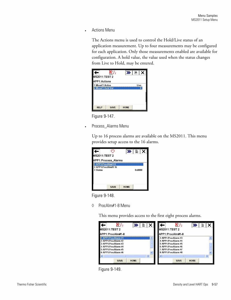
Actions Menu
The Actions menu is used to control the Hold/Live status of an application measurement. Up to four measurements may be configured for each application. Only those measurements enabled are available for configuration. A hold value, the value used when the status changes from Live to Hold, may be entered.
Figure 9-147.
Process_Alarms Menu
Up to 16 process alarms are available on the MS2011. This menu provides setup access to the 16 alarms.
Figure 9-148.
ProcAlm#1-8 Menu
This menu provides access to the first eight process alarms.
Figure 9-149.
Menu Samples MS2011 Setup Menu
9-58 Density and Level HART Ops Thermo Fisher Scientific
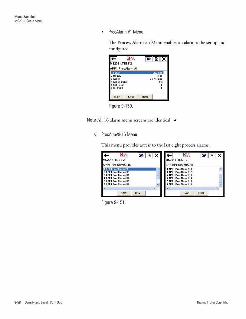
ProcAlarm #1 Menu
The Process Alarm #n Menu enables an alarm to be set up and configured.
Figure 9-150.
Note All 16 alarm menu screens are identical.
ProcAlm#9-16 Menu
This menu provides access to the last eight process alarms.
Figure 9-151.

Menu Samples MS2011 Setup Menu
Thermo Fisher Scientific Density and Level HART Ops 9-59
Status Menu
The process alarm Status menu indicates the current status of all 16 process alarms.
Figure 9-152.
Like the Quick Setup menu, the Detailed Setup menu for level allows a user to configure the primary measurement and perform standardization and calibration to configure an application. The menu is also used to configure measurement actions and process alarms.
Figure 9-153.
Level Menu
Menu Samples MS2011 Setup Menu
9-60 Density and Level HART Ops Thermo Fisher Scientific
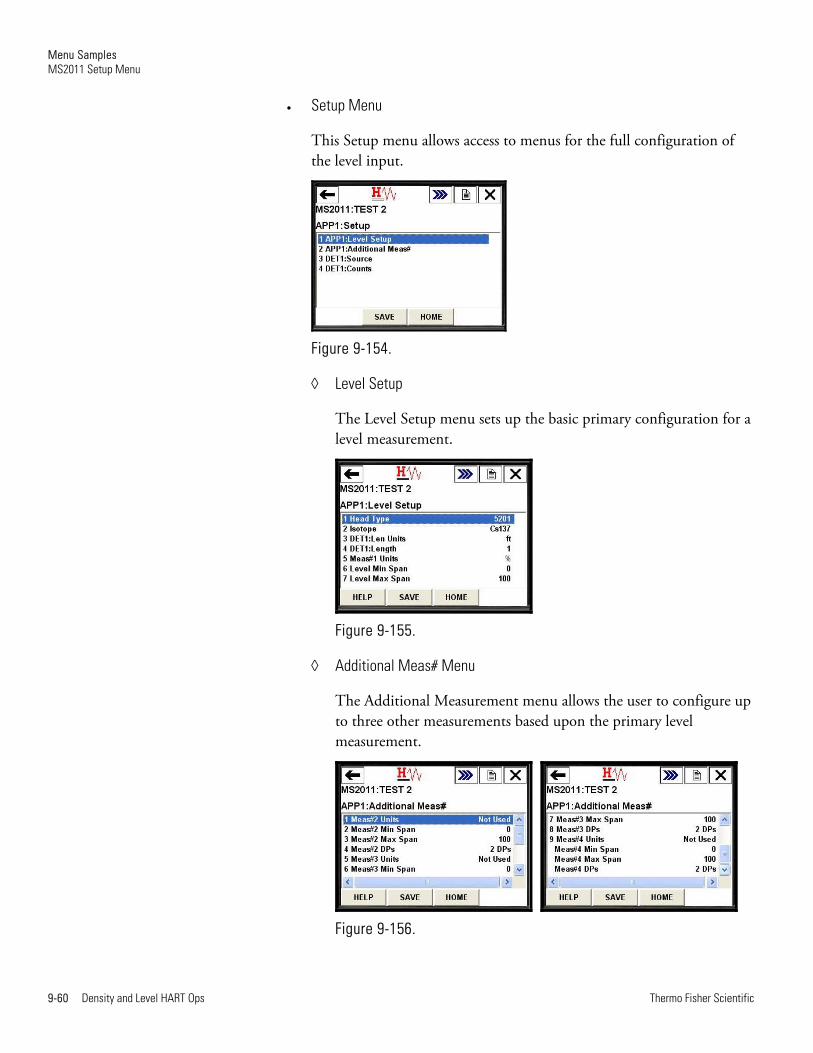
Setup Menu
This Setup menu allows access to menus for the full configuration of the level input.
Figure 9-154.
Level Setup
The Level Setup menu sets up the basic primary configuration for a level measurement.
Figure 9-155.
Additional Meas# Menu
The Additional Measurement menu allows the user to configure up to three other measurements based upon the primary level measurement.
Figure 9-156.
Menu Samples MS2011 Setup Menu
Thermo Fisher Scientific Density and Level HART Ops 9-61
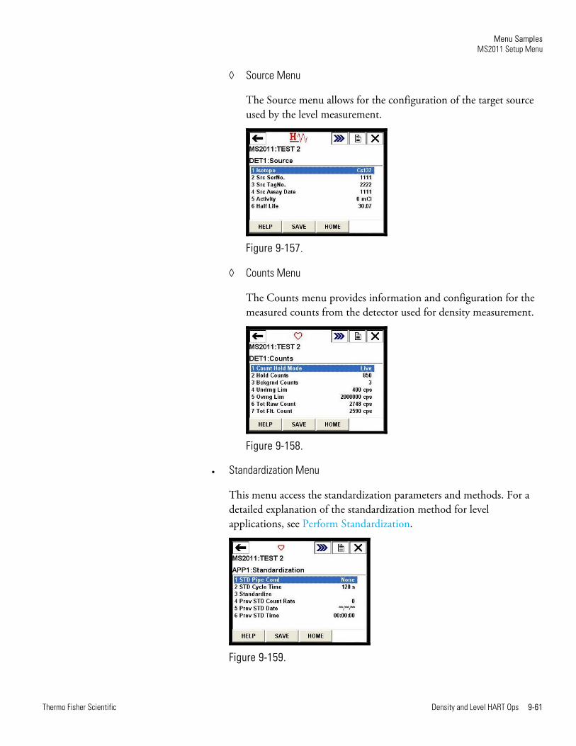
Source Menu
The Source menu allows for the configuration of the target source used by the level measurement.
Figure 9-157.
Counts Menu
The Counts menu provides information and configuration for the measured counts from the detector used for density measurement.
Figure 9-158.
Standardization Menu
This menu access the standardization parameters and methods. For a detailed explanation of the standardization method for level applications, see Perform Standardization.
Figure 9-159.
Menu Samples MS2011 Setup Menu
9-62 Density and Level HART Ops Thermo Fisher Scientific
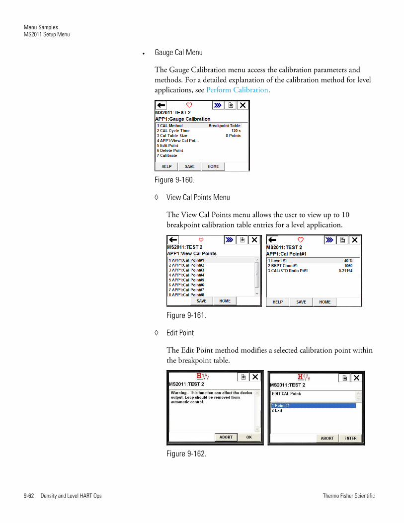
Gauge Cal Menu
The Gauge Calibration menu access the calibration parameters and methods. For a detailed explanation of the calibration method for level applications, see Perform Calibration.
Figure 9-160.
View Cal Points Menu
The View Cal Points menu allows the user to view up to 10 breakpoint calibration table entries for a level application.
Figure 9-161.
Edit Point
The Edit Point method modifies a selected calibration point within the breakpoint table.
Figure 9-162.
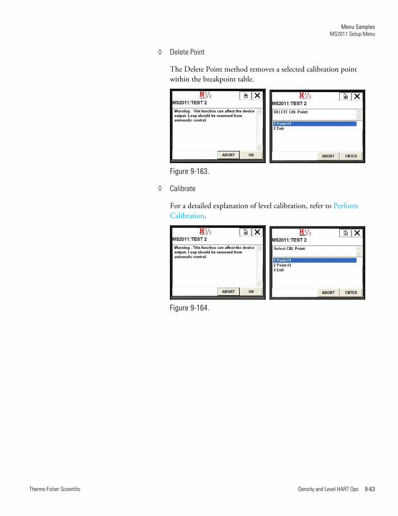
Menu Samples MS2011 Setup Menu
Thermo Fisher Scientific Density and Level HART Ops 9-63
Delete Point
The Delete Point method removes a selected calibration point within the breakpoint table.
Figure 9-163.
Calibrate
For a detailed explanation of level calibration, refer to Perform Calibration.
Figure 9-164.

Menu Samples MS2011 Setup Menu
9-64 Density and Level HART Ops Thermo Fisher Scientific
Actions Menu
The Actions menu is used to control the Hold/Live status of an application measurement. Up to four measurements may be configured for each application. Only those measurements enabled are available for configuration. A hold value, the value used when the status changes from Live to Hold, may be entered.
Figure 9-165.
Process_Alarms Menu
Up to 16 process alarms are available on the MS2011. This menu provides setup access to the 16 alarms.
Figure 9-166.
ProcAlm#1-8 Menu
This menu provides access to the first eight process alarms.
Figure 9-167.
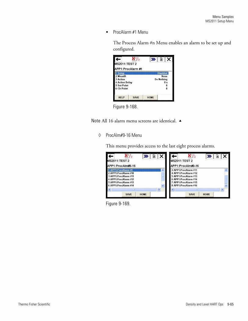
Menu Samples MS2011 Setup Menu
Thermo Fisher Scientific Density and Level HART Ops 9-65
ProcAlarm #1 Menu
The Process Alarm #n Menu enables an alarm to be set up and configured.
Figure 9-168.
Note All 16 alarm menu screens are identical.
ProcAlm#9-16 Menu
This menu provides access to the last eight process alarms.
Figure 9-169.
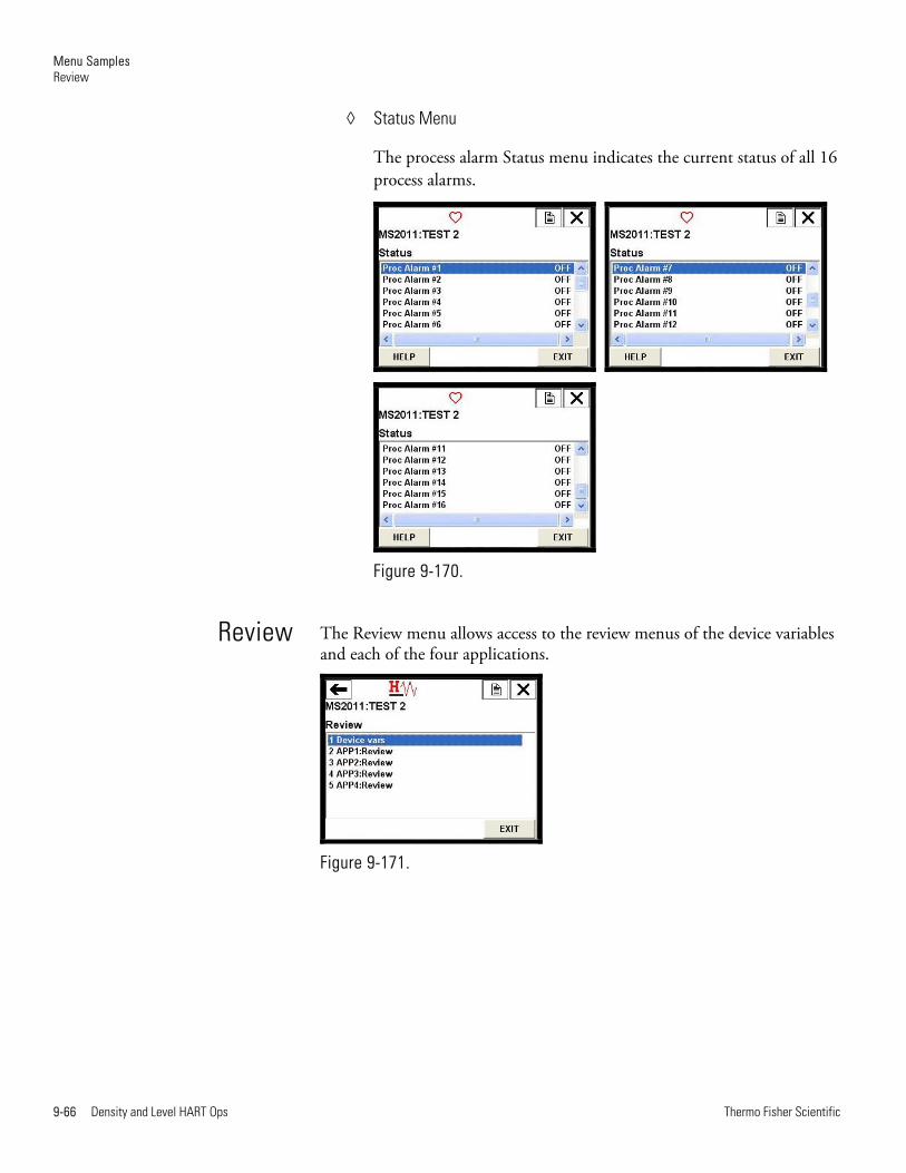
Menu Samples Review
9-66 Density and Level HART Ops Thermo Fisher Scientific
Status Menu
The process alarm Status menu indicates the current status of all 16 process alarms.
Figure 9-170.
The Review menu allows access to the review menus of the device variables and each of the four applications.
Figure 9-171.
Review
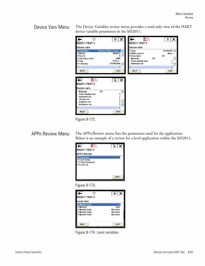
Menu Samples Review
Thermo Fisher Scientific Density and Level HART Ops 9-67
The Device Variables review menu provides a read-only view of the HART device variable parameters in the MS2011.
Figure 9-172.
The APPn:Review menu lists the parameters used for the application. Below is an example of a review for a level application within the MS2011.
Figure 9-173.
Figure 9-174. Level variables
Device Vars Menu
APPn:Review Menu
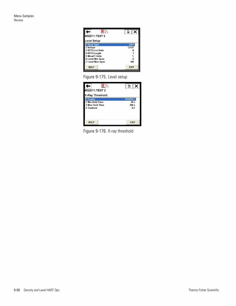
Menu Samples Review
9-68 Density and Level HART Ops Thermo Fisher Scientific
Figure 9-175. Level setup
Figure 9-176. X-ray threshold

Menu Samples Review
Thermo Fisher Scientific Density and Level HART Ops 9-69
Figure 9-177. Level calibration

Thermo Fisher Scientific81 Wyman StreetP.O. Box 9046Waltham, Massachusetts 02454-9046United States
www.thermofisher.com