guided waves along fluid-filled cracks in elastic … in elastic solids and ... wave motion in this...
TRANSCRIPT

Eric M. Dunham1
Assistant Professor
Department of Geophysics and Institute for
Computational and Applied Mathematics,
Stanford University,
Stanford, CA 94305
e-mail: [email protected]
Darcy E. OgdenAssistant Professor
Scripps Institution of Oceanography,
University of California, San Diego,
La Jolla, CA 92093
e-mail: [email protected]
Guided Waves Along Fluid-FilledCracks in Elastic Solids andInstability at High Flow RatesWe characterize wave propagation along an infinitely long crack or conduit in an elasticsolid containing a compressible, viscous fluid. Fluid flow is described by quasi-one-dimensional mass and momentum balance equations with a barotropic equation of state,and the wall shear stress is written as a general function of width-averaged velocity, den-sity, and conduit width. Our analysis focuses on small perturbations about steady flow,through a constant width conduit, at an unperturbed velocity determined by balancingthe pressure gradient with drag from the walls. Short wavelength disturbances propagaterelative to the fluid as sound waves with negligible changes in conduit width. The elasticwalls become more compliant at longer wavelengths since strains induced by opening orclosing the conduit are smaller, and the fluid compressibility becomes negligible. Aswavelength increases, the sound waves transition to crack waves propagating relative tothe fluid at a slower phase velocity that is inversely proportional to the square-root ofwavelength. Associated with the waves are density, velocity, pressure, and width pertur-bations that alter drag. At sufficiently fast flow rates, crack waves propagating in the flowdirection are destabilized when drag reduction from opening the conduit exceeds theincrease in drag from increased fluid velocity. This instability may explain the occurrenceof self-excited oscillations in fluid-filled cracks. [DOI: 10.1115/1.4005961]
1 Introduction
Fluid-filled cracks are ubiquitous in both the natural world andengineering applications. Examples include magma-filled dikes,water-filled crevasses and basal hydraulic fractures beneathglaciers and ice sheets, and induced hydraulic fractures in rockfilled with water or hydrocarbons. Seismic waves excited withinor around these fractures offer a powerful means of remotely dis-cerning fracture geometry and fluid properties.
Numerous authors have investigated wave propagation inthese systems, with special focus on guided waves confined to thevicinity of the fracture surface [1–4]. In this study we confine ourattention to planar cracks in an unbounded medium subject totwo-dimensional plane strain perturbations (Fig. 1(a)). We ideal-ize the crack as an infinitely long, straight conduit of nominallyconstant width; thus avoiding wave diffraction effects at the cracktips. This geometry supports the existence of dispersive wavesknown as slow waves or crack waves, for which the dominantrestoring force driving wave motion comes not from fluid com-pressibility but from elasticity of the conduit walls. Additionally,under more restrictive conditions, there are additional modes akinto Rayleigh waves.
Many previous studies have assumed an inviscid fluid initiallyat rest. In contrast, our reference state involves flow of a viscousfluid at a constant velocity determined by balancing the pressuregradient force with drag from the conduit walls. We find acritical velocity above which crack waves, or in some cases theRayleigh-like waves, are destabilized. Similar instabilities leadingto self-excited oscillations in fluid-filled cracks have been identi-fied previously, first in the context of a lumped-parameter model[5] and later in a more rigorous continuum framework for anincompressible fluid [6], and suggested as an explanation for
volcanic tremor. Our present study extends the latter analysis to acompressible fluid.
2 Width-Averaged Model
We restrict attention to wavelengths much larger than the crackwidth, which permits a width-averaged or quasi-one-dimensionalexpression of the fluid mass and momentum balance. The govern-ing equations, in conservation form, are
@ðqwÞ@tþ @ðquwÞ
@x¼ 0 (1)
Fig. 1 (a) Crack in unbounded elastic solid with opening 2w(x,t) containing fluid flowing in 1x direction with width-averagedvelocity u(x, t). (b) Perturbations in pressure (dp) and velocity(du) carried by sound=crack waves with negligible damping.Waves propagating in the 6x direction have du in phase withand of the same sign as 6dp. With the linearized equation ofstate, Eq. (10), density perturbations (dq) have the same sign asdp. For Fourier mode perturbations with phase velocities lessthan the Rayleigh speed, conduit width perturbations (dw) havethe same sign as dp.
1Corresponding author.Contributed by the Applied Mechanics Division of ASME for publication in the
JOURNAL OF APPLIED MECHANICS. Manuscript received August 21, 2011; final manu-script received January 13, 2012; accepted manuscript posted February 13, 2012;published online April 4, 2012. Assoc. Editor: Nadia Lapusta.
Journal of Applied Mechanics MAY 2012, Vol. 79 / 031020-1Copyright VC 2012 by ASME
Downloaded 12 Apr 2012 to 171.64.172.164. Redistribution subject to ASME license or copyright; see http://www.asme.org/terms/Terms_Use.cfm
@ðquwÞ@t
þ @ ðqu2 þ pÞw½ �@x
� p@w
@x¼ �s (2)
for density q, conduit half-width w, width-averaged velocity u,pressure p, and wall shear stress s. Alternatively, Eq. (2) can bewritten, using Eq. (1), as
q@u
@tþ u
@u
@x
� �¼ � @p
@x� s
w(3)
If gravity is included, then the pressure gradient term should bereplaced by the gradient in hydraulic potential.
We write the wall shear stress in the general form s¼ s(q, u, w)to encompass the wide range of flow regimes (from laminar to tur-bulent) that exist at various Reynolds numbers quw=l, where l isthe fluid viscosity. A widely used expression for turbulent flow iss¼ fqu2=8, where f is the Darcy-Weisbach friction factor. Anappropriate parametrization at high Reynolds number is [7] theManning-Strickler relation f¼ f0(j=2w)1=3, where f0 � 0.143 andj is the wall roughness. Hence,
s ¼ f0
8
j2w
� �1=3
qu2 (4)
In the opposite, low Reynolds number limit of fully developedlaminar flow of a linear viscous fluid,
s ¼ 3lu=w (5)
The assumption of fully developed flow requires that the timescales of interest (i.e., the wave period in this study) are muchlarger than the momentum diffusion time across the conduit width(�w2=(l=q)). This limits the applicability of our model andprevents us from properly investigating flow stability in parts ofparameter space that might be relevant for explaining volcanictremor in terms of self-excited oscillations [5,6]. Lifting thisrestriction requires abandoning the width-averaged flow descrip-tion, a task that is beyond the scope of the current analysis.
The description of the fluid is completed by an equation ofstate. We assume a barotropic equation of state, q¼ q(p), for
which the sound speed isffiffiffiffiffiffiffiffiffiffiffiffiffiffiffiffiffiffiffiffiffiffiðdq=dpÞ=q
p. This encompasses both
isothermal and adiabatic disturbances.Note that in this model we explicitly account for inertia, com-
pressibility, and drag from the walls (effects that have sometimesbeen neglected in prior studies). By including them, our model isquite general and we can precisely quantify the conditions underwhich certain effects can justifiably be ignored to simplify thefluid model. This is particularly the case for fluid compressibility,which can prevent self-excited oscillations by allowing pressureperturbations to be accommodated by compression or expansionof the fluid, rather than by wall deformation.
We are interested in perturbations about steady flow:
qðx; tÞ ¼ q0 þ dqðx; tÞ (6)
uðx; tÞ ¼ u0 þ duðx; tÞ (7)
pðx; tÞ ¼ @p
@x
� �0
xþ dpðx; tÞ (8)
wðx; tÞ ¼ w0 þ dwðx; tÞ (9)
The unperturbed fields are denoted with subscript 0 and the per-turbed fields are preceded by d. We have assumed for the unper-turbed flow that the conduit width is constant; the velocity issufficiently small, relative to the fluid sound speed, that inertialterms in the momentum balance can be neglected; and changes in
density along the conduit are negligible. The dominant balance isthus between the pressure gradient driving the flow and drag, andthe steady state velocity u0 is found by solving s0 � sðq0; u0; w0Þ¼ �w0 @p=@xð Þ0.
We next linearize the system of equations by assuming theperturbations are sufficiently small. The linearized equation ofstate is
dq ¼ q0
Kfdp (10)
where Kf is the fluid bulk modulus. Using Eq. (10), the linearizedmass and momentum balance equations are
Ddp
Dtþ q0c2
0
@du
@x¼ �Kf
w0
Ddw
Dt(11)
Ddu
Dtþ 1
q0
@dp
@x¼ � s0
q0w0
Audu
u0
þ Aqdp
Kf� Aw
dw
w0
� �(12)
in which c0 �ffiffiffiffiffiffiffiffiffiffiffiffiKf =q0
pis the sound speed and D=Dt � @=@t
þ u0@=@x is the rate of change of a quantity in a frame of refer-ence comoving with the unperturbed flow. The right side ofEq. (11) captures the influence of conduit width fluctuations onthe mass balance.
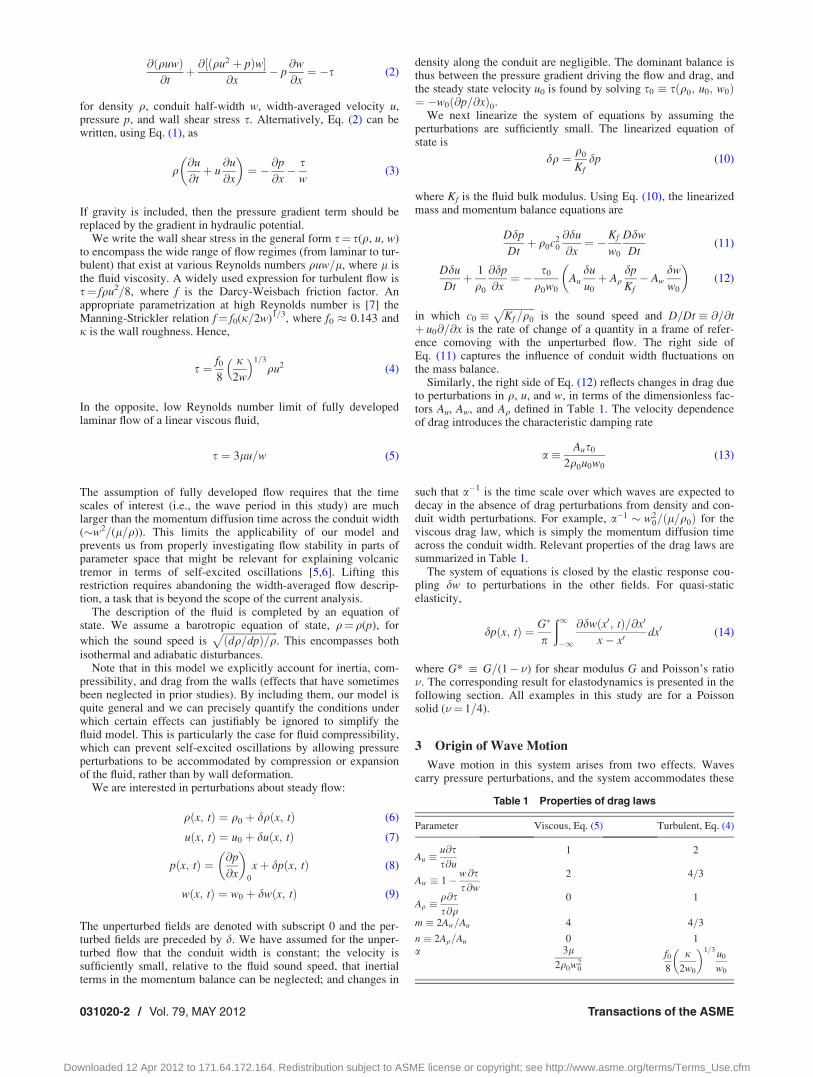
Similarly, the right side of Eq. (12) reflects changes in drag dueto perturbations in q, u, and w, in terms of the dimensionless fac-tors Au, Aw, and Aq defined in Table 1. The velocity dependenceof drag introduces the characteristic damping rate
a � Aus0
2q0u0w0
(13)
such that a�1 is the time scale over which waves are expected todecay in the absence of drag perturbations from density and con-duit width perturbations. For example, a�1 � w2
0=ðl=q0Þ for theviscous drag law, which is simply the momentum diffusion timeacross the conduit width. Relevant properties of the drag laws aresummarized in Table 1.
The system of equations is closed by the elastic response cou-pling dw to perturbations in the other fields. For quasi-staticelasticity,
dpðx; tÞ ¼ G�
p
ð1�1
@dwðx0; tÞ=@x0
x� x0dx0 (14)
where G* : G=(1� �) for shear modulus G and Poisson’s ratio�. The corresponding result for elastodynamics is presented in thefollowing section. All examples in this study are for a Poissonsolid (�¼ 1=4).
3 Origin of Wave Motion
Wave motion in this system arises from two effects. Wavescarry pressure perturbations, and the system accommodates these
Table 1 Properties of drag laws
Parameter Viscous, Eq. (5) Turbulent, Eq. (4)
Au �u
s@s@u
1 2
Aw � 1� w
s@s@w
2 4=3
Aq �qs@s@q
0 1
m � 2Aw=Au 4 4=3
n � 2Aq=Au 0 1a 3l
2q0w20
f08
j2w0
� �1=3 u0
w0
031020-2 / Vol. 79, MAY 2012 Transactions of the ASME
Downloaded 12 Apr 2012 to 171.64.172.164. Redistribution subject to ASME license or copyright; see http://www.asme.org/terms/Terms_Use.cfm
pressure changes either by compressing and expanding the fluid,or by opening and closing the conduit walls. The first effect isquantified by the fluid compressibility,
bf �1
q@q@p
� �w
¼ 1
Kf(15)
where the subscript w on the partial derivative indicates that con-duit width is held fixed. The associated wave speed is the soundspeed c0 � 1=
ffiffiffiffiffiffiffiffiffiq0bf
p.
The second source of wave motion comes from the restoringforce offered by elastic deformation of the conduit walls. Elastic-ity links conduit width perturbations to pressure perturbations. Weconsider the full elastodynamic response, with the quasi-staticresponse emerging as a limit.
Describing the elastic response, as well as assessing stabilityand examining wave motions, is facilitated by seeking modal sol-utions of the form
dpðx; tÞ ¼ dpðk; sÞ expðikxþ stÞ (16)
with similar notation applying to other fields. The perturbationwavelength is k � 2p=jkj. The phase velocity of the perturbationis c � �ImðsÞ=k and the growth=decay rate is Re(s). The quasi-static response, Eq. (14), transforms to dpðk; sÞ ¼ G�jkjdwðk; sÞ.The elastodynamic response introduces the P- and S-wave speedsof the solid, cp and cs, respectively, and generalizes this expres-sion to [8]
dpðk; sÞ ¼ G�jkjFðk; sÞ dwðk; sÞ; Fðk; sÞ � apð1� a2
s Þð1� �ÞR (17)
in which as�ffiffiffiffiffiffiffiffiffiffiffiffiffiffiffiffiffiffiffiffiffiffiffiffi1þðs=kcsÞ2
q, ap�
ffiffiffiffiffiffiffiffiffiffiffiffiffiffiffiffiffiffiffiffiffiffiffiffi1þðs=kcpÞ2
q, and R� 4asap
�ð1þa2s Þ
2is the Rayleigh function. The appropriate Riemann
sheet for the square roots is that for which Re ap� 0 and Reas� 0, which keeps fields from diverging with increasing distancefrom the conduit. For as, branch cuts in the complex s planeextend between ikcs and i1, and �ikcs and �i1, and likewise forap. (For more details, see Ref. [8].) Furthermore, we have definedthe function F such that F ! 1 as js=kcsj! 0 (i.e., in the quasi-static limit). Figure 2 illustrates properties of F(k, s) along theimaginary axis for phase velocities between zero and the S-wavespeed.
More precise versions of Eqs. (14) and (17) would also includecoupling between wall shear stress and conduit opening. Whileeasily included, dimensional analysis reveals that this effect is
several orders of magnitude smaller than the pressure-width cou-pling and we thus neglect it.
Equation (17) serves to define the conduit compressibility inthe quasi-static limit as:
bw �1
w
@w
@p
� �q
¼ 1
G�jkjw0
(18)
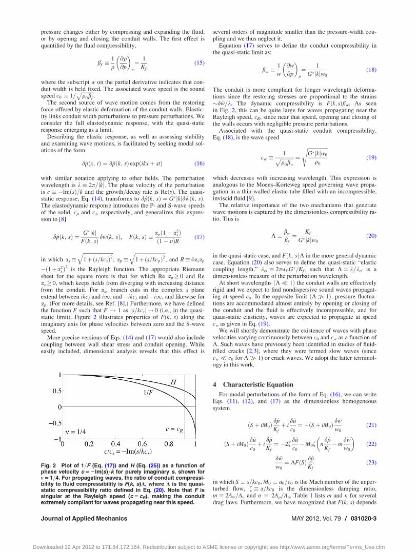
The conduit is more compliant for longer wavelength deforma-tions since the restoring stresses are proportional to the strains�dw=k. The dynamic compressibility is F(k, s)bw. As seenin Fig. 2, this can be quite large for waves propagating near theRayleigh speed, cR, since near that speed, opening and closing ofthe walls occurs with negligible pressure perturbations.
Associated with the quasi-static conduit compressibility,Eq. (18), is the wave speed
cw �1ffiffiffiffiffiffiffiffiffiffiq0bw
p ¼
ffiffiffiffiffiffiffiffiffiffiffiffiffiffiffiffiG�jkjw0
q0
s(19)
which decreases with increasing wavelength. This expression isanalogous to the Moens–Korteweg speed governing wave propa-gation in a thin-walled elastic tube filled with an incompressible,inviscid fluid [9].
The relative importance of the two mechanisms that generatewave motions is captured by the dimensionless compressibility ra-tio. This is
K � bw
bf
¼ Kf
G�jkjw0
(20)
in the quasi-static case, and Fðk; sÞK in the more general dynamiccase. Equation (20) also serves to define the quasi-static “elasticcoupling length,” kel � 2pw0G�=Kf , such that K ¼ k=kel is adimensionless measure of the perturbation wavelength.
At short wavelengths ðK 1Þ the conduit walls are effectivelyrigid and we expect to find nondispersive sound waves propagat-ing at speed c0. In the opposite limit ðK 1Þ, pressure fluctua-tions are accommodated almost entirely by opening or closing ofthe conduit and the fluid is effectively incompressible, and forquasi-static elasticity, waves are expected to propagate at speedcw as given in Eq. (19).
We will shortly demonstrate the existence of waves with phasevelocities varying continuously between c0 and cw as a function ofK. Such waves have previously been identified in studies of fluid-filled cracks [2,3], where they were termed slow waves (sincecw c0 for K 1) or crack waves. We adopt the latter terminol-ogy in this work.
4 Characteristic Equation
For modal perturbations of the form of Eq. (16), we can writeEqs. (11), (12), and (17) as the dimensionless homogeneoussystem
ðSþ iM0Þdp
Kfþ i
du
c0
¼ �ðSþ iM0Þdw
w0
(21)
ðSþ iM0Þdu
c0
þ idp
Kf¼ �2f
du
c0
�M0f ndp
Kf� m
dw
w0
� �(22)
dw
w0
¼ KFðSÞ dp
Kf(23)
in which S � s=kc0, M0 � u0=c0 is the Mach number of the unper-turbed flow, f � a=kc0 is the dimensionless damping ratio,m � 2Aw=Au and n : 2Aq=Au. Table 1 lists m and n for severaldrag laws. Furthermore, we have recognized that F(k, s) depends
Fig. 2 Plot of 1=F (Eq. (17)) and H (Eq. (25)) as a function ofphase velocity c 5 2Im(s)=k for purely imaginary s, shown form 5 1=4. For propagating waves, the ratio of conduit compressi-bility to fluid compressibility is F(k, s)K, where K is the quasi-static compressibility ratio defined in Eq. (20). Note that F issingular at the Rayleigh speed (c 5 cR), making the conduitextremely compliant for waves propagating near this speed.
Journal of Applied Mechanics MAY 2012, Vol. 79 / 031020-3
Downloaded 12 Apr 2012 to 171.64.172.164. Redistribution subject to ASME license or copyright; see http://www.asme.org/terms/Terms_Use.cfm
on k and s only through their ratio, permitting us to write F withonly a single argument, F¼F(S), in the above expression and allsubsequent ones.
In this notation, undamped sound waves propagating at speedc0 relative to the steady flow satisfy Sþ iM0 ¼ �i. In this expres-sion for S and all subsequent ones, the top sign will be associatedwith waves propagating with the flow and the bottom signwith waves propagating against it. Of course, for sufficiently largeM0 it is possible that both waves propagate in the þx direction.Some caution must be employed when taking the incompressiblefluid limit: while both c0 and K approach infinity, the ratioc0=
ffiffiffiffiKp� cw remains constant and provides the relevant velocity
scale.A nontrivial solution of Eqs. (21)–(23) exists only when the
determinant of the coefficient matrix vanishes. The resulting char-acteristic equation is
ðSþ iM0Þ2 þ 2fðSþ iM0Þ þ1
1þ KFðSÞ þ iM0fmKFðSÞ � n
1þ KFðSÞ ¼ 0
(24)
When M0¼ 0 and f¼ 0, Eq. (24) matches the dispersion equationfor crack waves in an inviscid, motionless fluid derived by Pailletand White [1] (their Eq. (3) in the jkjw0 1 limit) and independ-ently by Ferrazzini and Aki [3] (their Eq. (14b) in the jkjw0 1limit).
As the Rayleigh function has only two roots on the proper Rie-mann sheet, the function F(S) can be factored by introducing [10]
HðSÞ � FðSÞ 1þ ðS=SRÞ2h i
(25)
where �iSR are the Rayleigh poles (SR � cR=c0 where cR is theRayleigh-wave speed). The function H(S) is analytic in the com-plex S plane except across branch cuts along the imaginary axis,and H(S) � 1 when jSj SR (i.e., in the quasi-static limit); seeFig. 2. Equation (24) can thus be written as
DðSÞ � 1þ ðS=SRÞ2 þ KHðSÞh i
ðSþ iM0Þ2 þ 2fðSþ iM0Þh i
þ 1� inM0fð Þ 1þ ðS=SRÞ2h i
þ imM0fKHðSÞ ¼ 0: (26)
This characteristic equation or dispersion relation constitutes themain result of our analysis and the remainder of this manuscript isdevoted to studying its solutions.
5 Solutions of the Characteristic Equation
We now discuss the various wave solutions of Eq. (26). Thelimiting case of no fluid-solid coupling (Sec. 5.1) provides a foun-dation that facilitates understanding of the more complex solu-tions that emerge from interactions between the elastic andacoustic systems. Section 5.2 focuses on crack waves and the con-ditions under which unstable growth of these wave modes leads toself-excited oscillations. This section contains the most importantresults of this study. We complete our investigation by discussingother solutions in Sec. 5.3, though these are generally less interest-ing and relevant than the crack waves studied in the previoussection.
5.1 No Fluid-Solid Coupling. First consider the limitingcase K! 0 (the short wavelength limit), for which there areno interactions between the fluid and solid. Equation (26) can befactored as
1þ ðS=SRÞ2h i
ðSþ iM0Þ2 þ 2fðSþ iM0Þ þ 1� inM0fh i
¼ 0
(27)
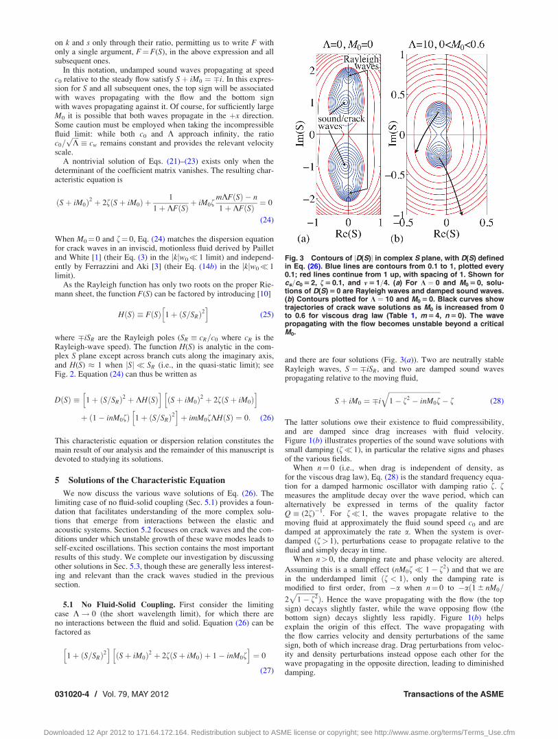
and there are four solutions (Fig. 3(a)). Two are neutrally stableRayleigh waves, S ¼ �iSR, and two are damped sound wavespropagating relative to the moving fluid,
Sþ iM0 ¼ �i
ffiffiffiffiffiffiffiffiffiffiffiffiffiffiffiffiffiffiffiffiffiffiffiffiffiffiffiffiffiffi1� f2 � inM0f
q� f (28)
The latter solutions owe their existence to fluid compressibility,and are damped since drag increases with fluid velocity.Figure 1(b) illustrates properties of the sound wave solutions withsmall damping (f 1), in particular the relative signs and phasesof the various fields.
When n¼ 0 (i.e., when drag is independent of density, asfor the viscous drag law), Eq. (28) is the standard frequency equa-tion for a damped harmonic oscillator with damping ratio f. fmeasures the amplitude decay over the wave period, which canalternatively be expressed in terms of the quality factorQ: (2f)�1. For f 1, the waves propagate relative to themoving fluid at approximately the fluid sound speed c0 and aredamped at approximately the rate a. When the system is over-damped (f> 1), perturbations cease to propagate relative to thefluid and simply decay in time.
When n> 0, the damping rate and phase velocity are altered.
Assuming this is a small effect (nM0f 1� f2) and that we arein the underdamped limit ðf < 1Þ, only the damping rate ismodified to first order, from �a when n¼ 0 to �að1 6 nM0=
2ffiffiffiffiffiffiffiffiffiffiffiffiffi1� f2
pÞ. Hence the wave propagating with the flow (the top
sign) decays slightly faster, while the wave opposing flow (thebottom sign) decays slightly less rapidly. Figure 1(b) helpsexplain the origin of this effect. The wave propagating withthe flow carries velocity and density perturbations of the samesign, both of which increase drag. Drag perturbations from veloc-ity and density perturbations instead oppose each other for thewave propagating in the opposite direction, leading to diminisheddamping.
Fig. 3 Contours of jD(S)j in complex S plane, with D(S) definedin Eq. (26). Blue lines are contours from 0.1 to 1, plotted every0.1; red lines continue from 1 up, with spacing of 1. Shown forcs=c0 5 2, f 5 0.1, and m 5 1=4. (a) For K ¼ 0 and M0 5 0, solu-tions of D(S) 5 0 are Rayleigh waves and damped sound waves.(b) Contours plotted for K ¼ 10 and M0 5 0. Black curves showtrajectories of crack wave solutions as M0 is increased from 0to 0.6 for viscous drag law (Table 1, m 5 4, n 5 0). The wavepropagating with the flow becomes unstable beyond a criticalM0.
031020-4 / Vol. 79, MAY 2012 Transactions of the ASME
Downloaded 12 Apr 2012 to 171.64.172.164. Redistribution subject to ASME license or copyright; see http://www.asme.org/terms/Terms_Use.cfm

5.2 Crack Waves and Instability Condition. Now weinclude fluid-solid coupling and focus on the crack wave solutionsfor nonzero K, which are generalizations of the sound wave solu-tions that exist in the K! 0 limit. We examine properties of thesecrack waves and show that they become unstable for sufficientlyfast fluid velocity u0.
We first assume that the relevant solutions have phase velocitiesmuch less than the elastic wave speeds. This is always the case ifcs=c0 1. Because crack waves are expected to have phasevelocities of order cw � c0=
ffiffiffiffiKp
, the assumption is also valid forarbitrary cs=c0 (even cs=c0< 1) if K is sufficiently large. Thereforethe elastic response is effectively quasi-static for these waves,permitting us to approximate 1þ (S=SR)2 � 1 and H(S) � 1 (seeFig. 2) in the characteristic equation, Eq. (26). The solutions thussatisfy
ðSþ iM0Þ2 þ 2fðSþ iM0Þ þ1
1þ Kþ iM0f
mK� n
1þ K¼ 0 (29)
The last term on the left side of Eq. (29) captures the drag pertur-bations from conduit width and density changes; the former leadsto instability under conditions identified below.
Before discussing that instability, consider the simpler casewhere that term can be neglected (e.g., for sufficiently small M0).We find
Sþ iM0 � �i
ffiffiffiffiffiffiffiffiffiffiffiffiffiffiffiffiffiffiffiffiffiffiffiffiffiffiffiffiffiffiffi1=ð1þ KÞ � f2
q� f (30)
Comparison with the rigid-wall sound wave solution, Eq. (28),suggests that these crack waves are generalizations of dampedsound waves, with reduced phase velocity due to the additionalsystem compliance arising from wall deformation. The relativesigns and phases of the fields, for f 1, are identical to those ofsound waves (Fig. 1(b)).
Since the walls are more deformable at longer wavelengths,crack waves exhibit anomalous dispersion, with shorter wave-length waves ðK 1Þ propagating at the damped fluid soundspeed. The longer wavelength waves ðK 1Þ satisfy Sþ iM0
� �iffiffiffiffiffiffiffiffiffiffiffiffiffiffiffiffiffiffiffi1=K� f2
q� f. Without damping, Sþ iM0 � �i=
ffiffiffiffiKp
.
Restoring dimensions, the phase velocity relative to the fluid
becomes the crack wave speed cw � c0=ffiffiffiffiKp
for an inviscid,incompressible fluid defined in Eq. (19). All dependence on fluidcompressibility and the fluid sound speed vanishes, indicating thatin this limit the restoring force responsible for wave motion comessolely from wall deformation and the fluid is effectively incom-pressible. As with sound waves, when damping is present and
exceeds a critical value ðf > 1=ffiffiffiffiffiffiffiffiffiffiffiffi1þ Kp
Þ, the waves become over-damped and cease to propagate.
When M0 is not sufficiently small that the last term on the leftside of Eq. (29) can be neglected, the solutions are
Sþ iM0 ¼ �i
ffiffiffiffiffiffiffiffiffiffiffiffiffiffiffiffiffiffiffiffiffiffiffiffiffiffiffiffiffiffiffiffiffiffiffiffiffiffiffiffiffiffiffiffiffiffiffiffiffiffiffiffiffi1
1þ K� f2 þ iM0f
mK� n
1þ K
r� f (31)
The wave propagating against the flow (the bottom sign) is alwaysstable. In contrast, the wave propagating with the flow (the topsign) becomes unstable if
M0 �u0
c0
>2ffiffiffiffiffiffiffiffiffiffiffiffi1þ Kp
mK� nor
u0
cw>
2ffiffiffiffiffiffiffiffiffiffiffiffiffiffiffiffiffi1þ 1=K
pm� n=K
(32)
which is shown in Fig. 4. For K 1, this instability conditionbecomes u0 > ð2=mÞcw, which is independent of c0 (as expectedin this incompressible fluid limit). Remarkably, the instabilitycondition is independent of the damping ratio f, although thegrowth rate does depend on f.
Figure 1(b) helps explain the origin of the instability. The wavepropagating with the flow carries velocity and pressure perturba-tions of the same sign. For quasi-static elasticity, the conduitwidth perturbations are of the same sign as the pressure perturba-tions. Hence, where velocity is largest, the conduit is widest.Instability occurs if the drag reduction from opening the conduitexceeds the additional drag from the faster flow.
When cs=c0 1, the quasi-static elasticity approximation iswell justified for crack waves of all wavelengths. This is no longerthe case if the crack wave phase velocity becomes comparable toelastic wave speeds, as occurs for smaller values of cs=c0. Toinvestigate this case, solutions are obtained by numerically solv-ing the characteristic equation, Eq. (26). For large values of K, thecrack waves have sufficiently reduced phase velocities that theelastic response is effectively quasi-static, even if cs=c0< 1.Hence the critical M0 for instability is identical to that found inthe quasi-static analysis (Fig. 4). As K decreases, we expect thesystem to become stiffer and the crack wave phase velocity toincrease. Opposing this is an increase in elastic compliance forphase velocities approaching the Rayleigh speed (Fig. 2). The neteffect is that the crack wave phase velocity asymptoticallyapproaches, but never surpasses, the Rayleigh wave speed of thesolid as K decreases, even if cw> cR. Furthermore, the critical M0
for instability is reduced relative to its quasi-static value (Fig. 4).This is because at phase velocities near the Rayleigh speed, onlysmall pressure changes are required for substantial wall deforma-tion, with the latter process promoting instability through dragreduction. The critical M0 again appears to be independent of f.
5.3 Additional Solutions. We continue by discussingRayleigh solutions for arbitrary K (i.e., the generalizations of theRayleigh waves found in the K! 0 limit). We first assume thatcs=c0> 1 (since the phenomenology changes rather dramaticallywhen cs=c0< 1). Our general result is that Rayleigh solutions existonly for small values of K and are never unstable. We then pro-ceed to the more complicated cs=c0< 1 case, where the distinctionbetween crack wave and Rayleigh solutions is less clear.
We initially assume cs=c0> 1, M0¼ 0, and f¼ 0. As can beverified a posteriori, the Rayleigh solutions for nonzero K, ifthey exist, have purely imaginary S with phase velocity c¼ ic0Ssatisfying cR< jcj< cs (i.e., they are neutrally stable waves withphase velocities between the Rayleigh and S-wave speeds). A use-ful way to write the characteristic equation, Eq. (26), is thus
ðc=cRÞ2 ¼ 1þ KHð�ic=c0Þ1� ðc0=cÞ2
(33)
Fig. 4 Critical Mach number, M0 : u0=c0, for instability, shownfor viscous drag law (Table 1, m 5 4, n 5 0). Red curve is forquasi-static elasticity (Eq. (32)) and blue curves show corre-sponding values with full elastodynamic response for severalvalues of cs=c0. Black curves show phase velocity c at neutralstability, which approaches but never exceeds the Rayleighspeed cR.
Journal of Applied Mechanics MAY 2012, Vol. 79 / 031020-5
Downloaded 12 Apr 2012 to 171.64.172.164. Redistribution subject to ASME license or copyright; see http://www.asme.org/terms/Terms_Use.cfm
which shows clearly that c ¼ 6cR when K ¼ 0 (a result thatremains true even if f 6¼ 0). Since H(S) is positive for cR < jcj< cs (Fig. 2) and c0=jcj < 1, the last term on the right side ofEq. (33) is positive real. Thus c must increase from cR at K ¼ 0 tocs at K ¼
ffiffiffi2pð1� �Þ3=2½1� ðc0=csÞ2� (an expression attained by
evaluating the characteristic equation at c¼ cs). When c0=cs 1and � ¼ 1=4, the maximum K � 0:92 (a limit which decreasesfor larger c0=cs). We verify, via numerical calculations, that theRayleigh solutions cease to exist for larger K. A similar phenome-nology also holds for f> 0 and M0> 0, except that the Rayleighsolutions are damped (though only mildly—in all cases studied,�1Re(S)� 0, regardless of the value of f).
When cs=c0< 1 we again generally find four solutions, twowith phase velocities close to the Rayleigh speed and two similarto sound waves. In this section, we provide some discussion ofthese solutions, particularly in certain limits, but caution that theinterplay between elastodynamics and acoustics is quite compli-cated and a more thorough investigation is likely warranted.
We first consider the cs=c0 1 limit. We expect sound wavesto have jSj � 1 SR. Since F(S) ! 0 as jSj=SR !1, then thecharacteristic equation, Eq. (24), has solutions identical to therigid-wall sound wave solutions, Eq. (28). That is simply becausethe elastic waves are so slow in this limit that the walls cannotdeform over the time scales associated with sound waves. Numer-ical results indicate that these solutions only exist for small K.
Rayleigh solutions in the cs=c0 1 limit are expected to havejSj � SR 1. For M0¼ 0 and f> 0, the characteristic equationsimplifies to
1þ ðS=SRÞ2 þ 2fSKHðSÞ � 0 (34)
The solutions have phase velocities close to cR and are slightlydamped. When M0> 0, the wave propagating against the flowbecomes damped at a faster rate, while the wave propagating inthe flow direction can become unstable.
We also point out properties of the Rayleigh solutions in themore general case of cs=c0< 1 but not necessarily cs=c0 1.When M0¼ 0 and f¼ 0, the waves are neutrally stable. The analy-sis leading up to Eq. (33) applies also to this case, except that thelast term on the right side of Eq. (33) is negative real. Conse-quently, solutions exist for all K, and their phase velocitydecreases from cR at K ¼ 0 toward zero as K increases.
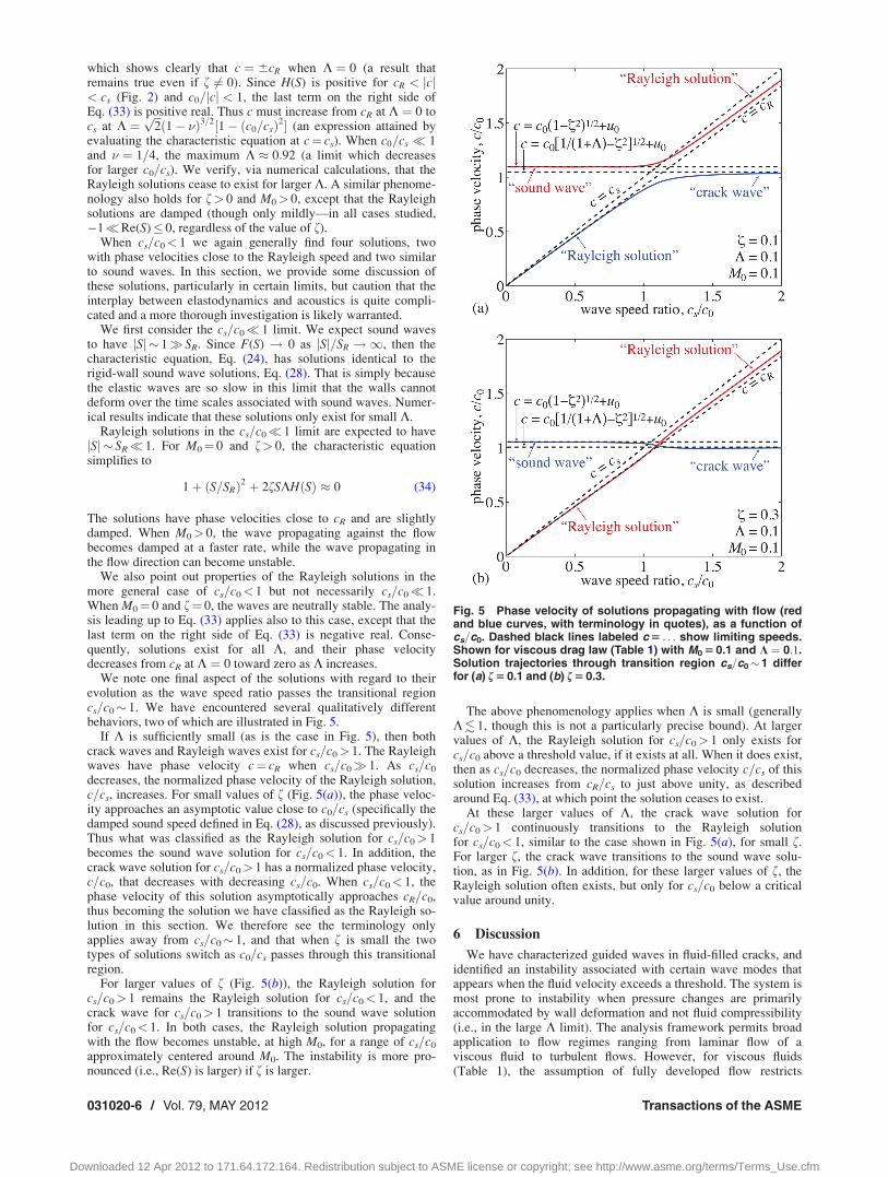
We note one final aspect of the solutions with regard to theirevolution as the wave speed ratio passes the transitional regioncs=c0� 1. We have encountered several qualitatively differentbehaviors, two of which are illustrated in Fig. 5.
If K is sufficiently small (as is the case in Fig. 5), then bothcrack waves and Rayleigh waves exist for cs=c0> 1. The Rayleighwaves have phase velocity c¼ cR when cs=c0 1. As cs=c0
decreases, the normalized phase velocity of the Rayleigh solution,c=cs, increases. For small values of f (Fig. 5(a)), the phase veloc-ity approaches an asymptotic value close to c0=cs (specifically thedamped sound speed defined in Eq. (28), as discussed previously).Thus what was classified as the Rayleigh solution for cs=c0> 1becomes the sound wave solution for cs=c0< 1. In addition, thecrack wave solution for cs=c0> 1 has a normalized phase velocity,c=c0, that decreases with decreasing cs=c0. When cs=c0< 1, thephase velocity of this solution asymptotically approaches cR=c0,thus becoming the solution we have classified as the Rayleigh so-lution in this section. We therefore see the terminology onlyapplies away from cs=c0� 1, and that when f is small the twotypes of solutions switch as c0=cs passes through this transitionalregion.
For larger values of f (Fig. 5(b)), the Rayleigh solution forcs=c0> 1 remains the Rayleigh solution for cs=c0< 1, and thecrack wave for cs=c0> 1 transitions to the sound wave solutionfor cs=c0< 1. In both cases, the Rayleigh solution propagatingwith the flow becomes unstable, at high M0, for a range of cs=c0
approximately centered around M0. The instability is more pro-nounced (i.e., Re(S) is larger) if f is larger.
The above phenomenology applies when K is small (generallyK. 1, though this is not a particularly precise bound). At largervalues of K, the Rayleigh solution for cs=c0> 1 only exists forcs=c0 above a threshold value, if it exists at all. When it does exist,then as cs=c0 decreases, the normalized phase velocity c=cs of thissolution increases from cR=cs to just above unity, as describedaround Eq. (33), at which point the solution ceases to exist.
At these larger values of K, the crack wave solution forcs=c0> 1 continuously transitions to the Rayleigh solutionfor cs=c0< 1, similar to the case shown in Fig. 5(a), for small f.For larger f, the crack wave transitions to the sound wave solu-tion, as in Fig. 5(b). In addition, for these larger values of f, theRayleigh solution often exists, but only for cs=c0 below a criticalvalue around unity.
6 Discussion
We have characterized guided waves in fluid-filled cracks, andidentified an instability associated with certain wave modes thatappears when the fluid velocity exceeds a threshold. The system ismost prone to instability when pressure changes are primarilyaccommodated by wall deformation and not fluid compressibility(i.e., in the large K limit). The analysis framework permits broadapplication to flow regimes ranging from laminar flow of aviscous fluid to turbulent flows. However, for viscous fluids(Table 1), the assumption of fully developed flow restricts
Fig. 5 Phase velocity of solutions propagating with flow (redand blue curves, with terminology in quotes), as a function ofcs=c0. Dashed black lines labeled c 5 . . . show limiting speeds.Shown for viscous drag law (Table 1) with M0 5 0.1 and K ¼ 0:1.Solution trajectories through transition region cs=c0�1 differfor (a) f 5 0.1 and (b) f 5 0.3.
031020-6 / Vol. 79, MAY 2012 Transactions of the ASME
Downloaded 12 Apr 2012 to 171.64.172.164. Redistribution subject to ASME license or copyright; see http://www.asme.org/terms/Terms_Use.cfm

application of our model to long period or highly damped waves.In terms of the dimensionless variables, this condition isf& 1=
ffiffiffiffiffiffiffiffiffiffiffiffi1þ Kp
.Unfortunately, this prevents us from rigorously assessing the vi-
ability of this model in explaining volcanic tremor as self-excitedoscillations from magma flowing through dikes, as the most rele-vant parts of parameter space do not quite satisfy this restriction.Dikes with w� 1 m filled with basalt (l=q� 10�2� 1 m2=s) havedamping rate a� 10�2� 1 s�1. Typical rock and magma proper-ties result in an elastic coupling length kel� 10 m, at least atdepths where gas exsolution is minimal and magma is primarilyliquid melt. Wavelengths of interest approach �1 km, givingK � 100 and f � 10�3 � 10�1. For these parameters, the relevantrestoring force for waves comes from wall deformation ratherthan fluid compressibility, such that crack waves propagate atspeed cw� 100 m=s. The elastic response is effectively quasi-static so the instability condition is u0> 0.5cw� 50 m=s. Thesevelocities are an order of magnitude larger than typically inferredin fissure eruptions, especially at depth. Closer to the surface, gasexsolution leads to larger velocities, but decreased K due toincreased fluid compressibility.
Narrower dikes have larger conduit compressibility bw and thusK, making the system more prone to instability. However, thesteady flow velocity u0 would be substantially reduced for a givenpressure gradient due to increased drag. If instead of magma, weconsider steam or other hydrothermal fluids [6], the fluid compres-sibility will be larger, thereby decreasing K and increasing thethreshold velocity for instability well above expected values.
Harmonic tremor has presumably also been observed on icesheets during rapid subglacial lake drainage events [11]. We tenta-tively apply our model to hydraulic fractures along the ice-rockinterface, although this violates our assumption that the crack sep-arates identical elastic half-spaces. Proceeding nonetheless, forinteresting parts of parameter space, K is sufficiently large thatcrack wave speeds are well below the elastic wave speed andthe elastic response is quasi-static. For the turbulent flow law(Table 1) in this limit, the instability condition is u0> 1.5cw.Taking q0 � 1000 kg=m3 and G* � 5 GPa,
cw � 180100 m
k
� �1=2 w0
0:1 m
� �1=2
m=s (35)
The predicted u0 for instability is one or two orders of magnitudelarger than inferred subglacial fluid velocities [7]. Furthermore,f 1 so predicted growth rates of the instability would be quitelow, even if it were to exist.
We therefore tentatively conclude that seismic tremor observedin both volcanoes and glaciers is unlikely to arise from self-excited oscillations via the crack wave instability we haveidentified. However, we do speculate that crack waves likely playa central role in tremor, as has been suspected in volcanic systemsfor many years [2,3]. In the absence of self-excitation, sustainedperturbations from disturbances in either the fluid or solid (burst-ing of gas bubbles or fracture of conduit walls, for example) arerequired to continually excite crack waves. Investigations intopotential excitation mechanisms and their observational signaturesare warranted.
Acknowledgment
We thank Leif N. Thomas for valuable discussions in the earlystages of this work. This work was supported by NSF Grant No.EAR-1114073.
NomenclatureD(S) ¼ characteristic equationF(S) ¼ elastodynamic transfer function
G ¼ solid shear modulusH(S) ¼ elastodynamic transfer function after removal of
Rayleigh polesKf ¼ fluid bulk modulus
M0 � u0=c0 ¼ Mach numberS � s=kc0 ¼ nondimensional perturbation time dependence
SR � cR=c0 ¼ wave-speed ratioc � ImðsÞ=k ¼ phase velocity of perturbation
c0 �ffiffiffiffiffiffiffiffiffiffiffiffiKf =q0
p¼ fluid sound speed
cp ¼ solid P-wave speedcR ¼ solid Rayleigh-wave speedcs ¼ solid S-wave speedcw ¼ crack wave phase velocity for incompressible,
inviscid fluidk ¼ perturbation wavenumber
m ¼ dependence of s on wn ¼ dependence of s on q
p(x,t) ¼ fluid pressures ¼ perturbation time dependencet ¼ timex ¼ distance along crack
u(x, t) ¼ fluid velocity (width-averaged)w(x, t) ¼ conduit half-width
a ¼ damping ratebf ¼ fluid compressibilitybw ¼ conduit compressibility
dð Þ ¼ perturbed field ð Þk ¼ perturbation wavelengthK ¼ quasi-static compressibility ratiol¼ fluid viscosity� ¼ solid Poisson’s ratio
qðx; tÞ ¼ fluid densitysðx; tÞ ¼ wall shear stress
f ¼ damping ratioð Þ0 ¼ unperturbed field ð Þ
References[1] Paillet, F. L., and White, J. E., 1982, “Acoustic Modes of Propagation in the
Borehole and Their Relationship to Rock Properties,” Geophys., 47(8), pp.1215–1228.
[2] Chouet, B., 1986, “Dynamics of a Fluid-Driven Crack in Three Dimensions bythe Finite Difference Method,” J. Geophys. Res., 91(B14), pp 13,967–13, 992.
[3] Ferrazzini, V., and Aki, K., 1987, “Slow Waves Trapped in a Fluid-Filled Infi-nite Crack: Implications for Volcanic Tremor,” J. Geophys. Res., 92(B9), pp.9215–9223.
[4] Korneev, V., 2008, “Slow Waves in Fractures Filled with Viscous Fluid,” Geo-phys., 73(1), pp. N1–N7.
[5] Julian, B., 1994, “Volcanic Tremor: Nonlinear Excitation by Fluid Flow,” J.Geophys. Res., 99(B6), pp 11,859–11, 877.
[6] Balmforth, N. J., Craster, R. V., and Rust, A. C., 2005, “Instability in FlowThrough Elastic Conduits and Volcanic Tremor,” J. Fluid Mech., 527, pp.353–377.
[7] Tsai, V. C., and Rice, J. R., 2010, “A Model for Turbulent Hydraulic Fractureand Application to Crack Propagation at Glacier Beds,” J. Geophys. Res., 115.
[8] Geubelle, P. H., and Rice, J. R., 1995, “A Spectral Method for Three-Dimen-sional Elastodynamic Fracture Problems,” J. Mech. Phys. Solids, 43, pp.1791–1824.
[9] Pedley, T. J., 1980, The Fluid Mechanics of Large Blood Vessels, CambridgeUniversity Press, Cambridge.
[10] Rahman, M., and Barber, J. R., 1995, “Exact Expressions for the Roots of theSecular Equation for Rayleigh Waves,” ASME J. Appl. Mech., 62(1), pp.250–252.
[11] Winberry, J. P., Anandakrishnan, S., and Alley, R. B., 2009, “Seismic Observa-tions of Transient Subglacial Water-Flow Beneath MacAyeal Ice Stream, WestAntarctica,” Geophys. Res. Lett., 36.
Journal of Applied Mechanics MAY 2012, Vol. 79 / 031020-7
Downloaded 12 Apr 2012 to 171.64.172.164. Redistribution subject to ASME license or copyright; see http://www.asme.org/terms/Terms_Use.cfm