guidelines for on-site stormwater detention
TRANSCRIPT

GUIDELINES FOR
ON-SITE STORMWATER
DETENTION
Adopted: May 2009

Melton Shire Council Guidelines for On-site Stormwater Detention
Report Prepared by: Engineering Services 2009 Page 1
Table of Contents
1.0 INTRODUCTION 3
2.0 NEED FOR ON-SITE STORMWATER DETENTION 4
3.0 PRINCIPLES OF ON- SITE STORMWATER DETENTION 4
4.0 DESIGN & CONSTRUCTION PARAMETERS & DETAILS FOR OSD 5
4.1 DESIGN PARAMETERS 5
4.2 DESIGN DETAILS 5 4.2.1 On-site Storage Volume (Vs) 5
4.2.1.1 Underground Storage Systems 6
4.2.1.2 Surface Storage Systems 6
4.2.1.2.1 Ponding Limits 6
4.2.1.3 Rainwater Tanks 7
4.3 FLOW CONTROL OUTLET 8 4.3.1 Orifice System 8
4.3.2 Multi Cell 10
4.4 ON SITE STORAGE DETENTION CALCULATION 11
4.4.1 Calculation using OSD4 package 12
4.5 PUMP-OUT SYSTEM 12
5.0 INFORMATION REQUIRED TO BE SUBMITTED 12
5.1 INITIAL SUBMISSION. 12
5.1.1 Information required on drainage drawings. 13
5.1.2 Information required on calculation sheets 13
5.2 FINAL SUBMISSION. 14
6.0 POST DEVELOPMENT DOCUMENTATION 14
7.0 GLOSSARY 14
8.0 REFERENCES 14

Melton Shire Council Guidelines for On-site Stormwater Detention
Report Prepared by: Engineering Services 2009 Page 2
9.0 CONTACT INFORMATION 15

Melton Shire Council Guidelines for On-site Stormwater Detention
Report Prepared by: Engineering Services 2009 Page 3
1.0 Introduction
Redevelopment of a site usually increases the area covered by hard impervious surfaces such as roofing and paving. The change in the average permeability of the site significantly increases the volume and flow rate of storm water runoff and the additional drainage loads may cause local flash flooding downstream of the site. Due to the number of residential redevelopments and other redevelopments taking place within the Shire, it has become necessary to limit the peak rate of runoff reaching the Council’s drainage system. On-site Stormwater Detention (OSD) is a stormwater management technique that enables the runoff discharge rates of individual development sites to be controlled. An OSD system requires a flow control device to limit the discharge to an acceptable rate and a storage system to hold the excess discharge until capacity becomes available in the downstream drainage system. Large detention basins are expensive even if built on public land and only provide protection against downstream flooding. Properties upstream of a detention basin are not protected from the increased runoff caused by redevelopment. Well-designed OSD systems control the peak discharge rates to match the capacity of the downstream drainage system. The total volume of stormwater leaving the site is not reduced but the retained volume is released when downstream drainage capacity becomes available. Requiring the installation of OSD systems on redevelopment sites ensures there are no adverse impacts from stormwater runoff on downstream properties as a result of ongoing development in the catchment.

Melton Shire Council Guidelines for On-site Stormwater Detention
Report Prepared by: Engineering Services 2009 Page 4
2.0 Need for On-Site Stormwater Detention The design and construction of an OSD system to control runoff from a site will be required for developments in the Shire of Melton that result in increased impervious areas above the original designed values. A requirement of an OSD system is expected as a condition on the planning permit. And the number of dwellings/buildings is immaterial.
3.0 Principles of On- site Stormwater Detention On-site Stormwater Detention systems are used as part of the stormwater drainage system to reduce the impacts of site development on receiving drains and waterways. At the onset of a storm, stormwater will commence to discharge from the site. The earliest flow will be from areas nearest the discharge point but will increase significantly as water from the furthest points of the property reaches the discharge point. As the intensity of the storm approaches its peak, the discharge rate will increase relatively sharply to a maximum. The discharge rate will subside after the peak has passed. If the highest discharge rate for the catchment’s critical storm event will exceed the permissible site discharge (PSD) rate, as indicated by the Responsible Authority, an on-site stormwater detention (OSD) system will have to be installed. The system will temporarily store any excess flow and release it at a controlled lower rate over a longer period of time. A detention system has two components – a device to control the flow rate of the discharge from the site and storage for the excess stormwater. The storage can be provided via underground or aboveground pipes or tanks. Ground level storage is provided by allowing water to pond in a broad but shallow depression in a paved area such as a driveway.
Melton Shire Council Guidelines for On-site Stormwater Detention
Report Prepared by: Engineering Services 2009 Page 5
4.0 Design & Construction Parameters & Details for OSD
OSD designs shall be prepared by a suitably qualified and registered engineering consultant, in accordance with the Council’s requirement.
4.1 Design Parameters Key aspects of the OSD procedure are to determine the Permissible Site Discharge (PSD) and Storage Volume (Vs) for the storage configuration that is adopted by the designer. The following are the main criteria required to determine the PSD and Vs. Site area. Weighted coefficient of runoff at the initial subdivision stage – information
shall be obtained from Council. Weighted coefficient of runoff at the post development stage. Time of concentration for the entire catchment, which relevant site has been
located – information shall be obtained from Council. Travel time from the site discharge point to the catchment outlet – information
shall be obtained from Council. Average Recurrence Intervals:
For the permissible site discharge, o Residential area – 5 year ARI o Industrial area – 10 year ARI
Site Storage Requirement: o Residential area – 10 year ARI o Industrial area – 20 year ARI
4.2 Design Details 4.2.1 On-site Storage Volume (Vs) The minimum volume of the on-site storage depends upon the following. Permissible Site Discharge Adopted storage system and/or configuration And a number of the parameters listed in 4.1 above.
NOTE: If storm events of the same ARI, but having durations more than the catchment specific critical duration, cause the storage to overflow, it will be necessary to increase the storage volume. The designer will be required to “maximise” the storage volume to ensure that the system does not fail for a storm event of any duration.
Melton Shire Council Guidelines for On-site Stormwater Detention
Report Prepared by: Engineering Services 2009 Page 6
4.2.1.1 Underground Storage Systems Underground storage systems are suitable for use as OSD storages. These systems should be located in areas where they can be readily accessed for inspections and maintenance. These systems must be watertight. Otherwise, if there is the potential for water seepage, this may cause damage to adjacent properties or structures. Where possible, a “visible overflow” should be built into the system. 4.2.1.2 Surface Storage Systems
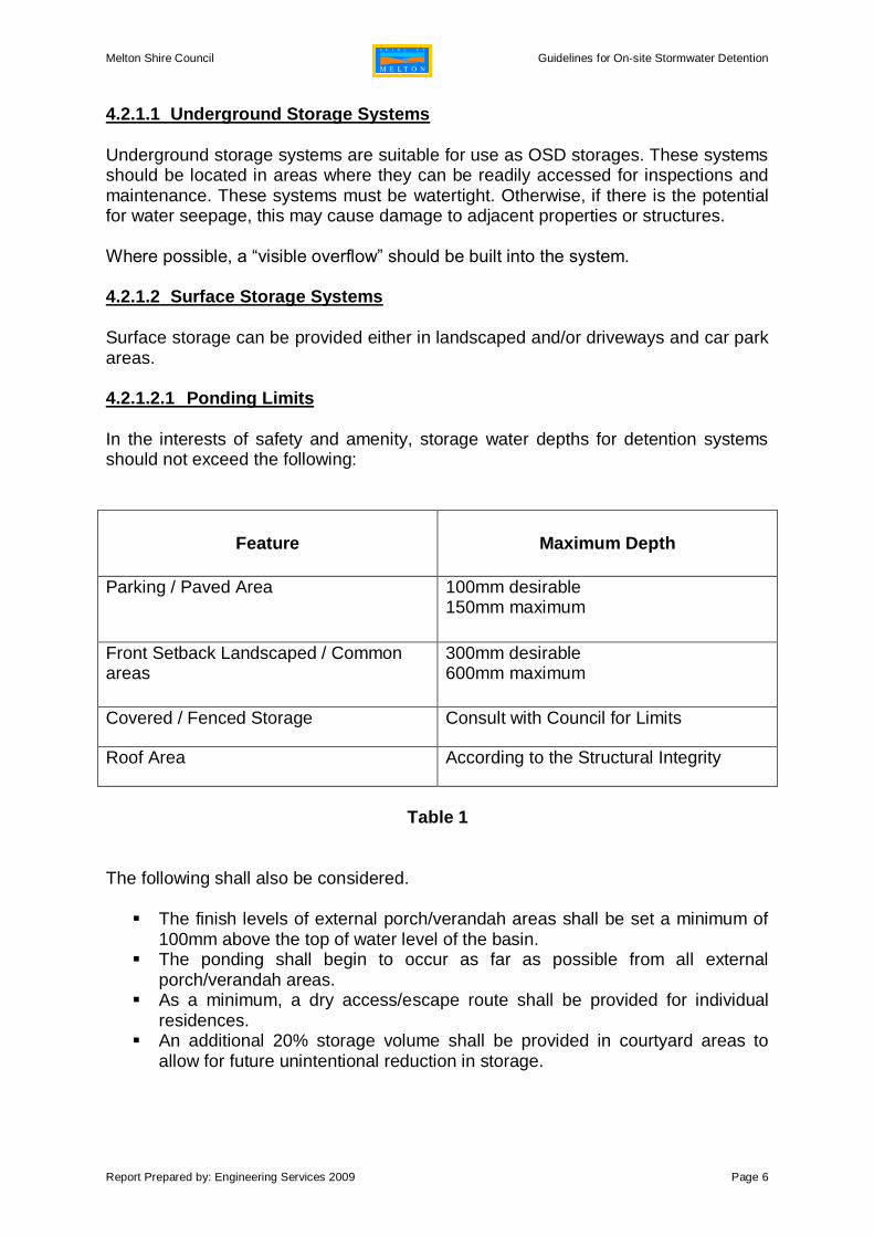
Surface storage can be provided either in landscaped and/or driveways and car park areas. 4.2.1.2.1 Ponding Limits In the interests of safety and amenity, storage water depths for detention systems should not exceed the following:
Feature Maximum Depth
Parking / Paved Area 100mm desirable 150mm maximum
Front Setback Landscaped / Common areas
300mm desirable 600mm maximum
Covered / Fenced Storage Consult with Council for Limits
Roof Area According to the Structural Integrity
Table 1
The following shall also be considered. The finish levels of external porch/verandah areas shall be set a minimum of
100mm above the top of water level of the basin. The ponding shall begin to occur as far as possible from all external
porch/verandah areas. As a minimum, a dry access/escape route shall be provided for individual
residences. An additional 20% storage volume shall be provided in courtyard areas to
allow for future unintentional reduction in storage.

Melton Shire Council Guidelines for On-site Stormwater Detention
Report Prepared by: Engineering Services 2009 Page 7
4.2.1.3 Rainwater Tanks
Rainwater tanks may be acceptable for providing some of the OSD storage volume. If the developer/consultant proposes to use rainwater tanks, the rainwater tank shall be modified to comply with Figure 1 and other comments listed below. Council accepts the following types of design:
Rainwater tank for each unit/dwelling/building that collects water from the roof of both unit/dwelling/building and garage. The maximum temporary storage (airspace) of tanks shall not be exceeded one third of the total site storage amount. However, the temporary storage volume provided in the rainwater tanks cannot exceed one third of the rainwater tank or on third of the total storage requirement whichever is lesser.
The roof area/impervious area connected to the rainwater tank shall be
proportionately equal to the percentage of temporary storage within the rainwater tank.
Controlled outflow from the airspace of each rainwater tank shall be a
maximum 1 l/s. This would require a 25-30 mm diameter outlet from the rainwater tank if the outlet is located approximately 600mm below the top of the rainwater tank.
To avoid having a closed system (ie. To get rid of the effect of additional
water head), the 100mm diameter outlet pipe connected to the tank shall have a 25-30mm diameter orifice to restrict flow. The outflow pipe shall then connect to a minimum 450x450mm pit with grated cover (Refer Figure 1) prior to connecting to the subject site’s underground drainage system.

Melton Shire Council Guidelines for On-site Stormwater Detention
Report Prepared by: Engineering Services 2009 Page 8
Domestic usage storage
Temporary storage
Max. water level
RAINWATER TANK
Bedding material
Inflow to tank
(from sealed SW pipe)
Alt. inlet to tank
(from roof gutter)
Inspection openning
Inspection opening
Outlet with gate valve
(for draining of tank)
Overflow
25-30mm dia. Orifice
in tank side (sealed)
To underground
drainage system
450x450mm pit with
25x25mm grated lid
Figure 1 Note: Details of connection of down pipes to the rainwater tank can be seen from the publications of Plumbing Industry Commission.
4.3 Flow Control Outlet The outlet shall be designed such that the flow going into the Council drainage system is limited to the Permissible Site Discharge when the storage is at the OSD storage volume (Vs). Acceptable flow control outlet types are; Orifice System Multi Cell
4.3.1 Orifice System The size of the orifice designed using an orifice formula. PSD = CAV Where, V2 = 2gh A = πd2/4 C = orifice coefficient Easily applicable format is, d = 21.9 x [PSD / (h1/2)]1/2

Melton Shire Council Guidelines for On-site Stormwater Detention
Report Prepared by: Engineering Services 2009 Page 9
Where, h is the water head for the orifice (height between centreline of the orifice pipe
and maximum level of the temporary site storage) in metres PSD is the Permissible Site Discharge in litres per second d is the diameter of the orifice in millimetres.
The minimum size of the orifice that Council will accept is 50mm. It requires the provision of a 20x20mm trash grate over the orifice inlet when the orifice size in between 50-100mm. Figure 2 shows the approved orifice pit design, which includes a baffle wall. A grated pit cover shall be used above the detention chamber of the orifice pit to be provided for casual inspection and possibly visible and audible indications. A solid cover above the outfall chamber of the orifice pit shall be used in order to avoid any uncontrolled water bypassing the system.
Orifice at base of baffle wall
Flow Direction.
Section A-A Section B-B
Plan
B
B
A A
Detention Chamber Outlet Chamber
100mm minimum
Suitable angled trash
grate
Storage Pipe Outlet pipe to be connected
to the existing Council drain
ORIFICE PIT ARRANGEMENT WITH BAFFLE WALL
Grated Cover Gatic Cover Grated Cover
Figure 2
The highest point of the underground storage system shall not be higher than the top of the baffle wall in the orifice pit.

Melton Shire Council Guidelines for On-site Stormwater Detention
Report Prepared by: Engineering Services 2009 Page 10
Figure 3 shows the typical cross section of the Orifice Plate.
Figure 3
4.3.2 Multi Cell
Figure 4 shows a sample layout arrangement of the multi cells for above ground and below ground storage systems.
1815
1875
Lawn edge
Maximum designed
storage depth
Slotted
Orifice
Discharge to
Council system
50mm sand base
ABOVE GROUND STORAGE
1815
1875
Slotted
Orifice
Discharge to
Council system
50mm sand base
BELOW GROUND STORAGE
Figure 4 Council will assess, for approval, a multi cell system only with the attachment of the relevant charts justifying the model of the proposed multi cell.

Melton Shire Council Guidelines for On-site Stormwater Detention
Report Prepared by: Engineering Services 2009 Page 11
Figure 5 shows a sample chart that is used to select the type of the multi cell, according to the inlet head.
Figure 5
4.4 On Site Storage Detention Calculation Council’s preferred method to calculate for On-site Stormwater Detention is by the use of the OSD4 computer program. Council, however, does not object to other software packages being used to generate designs based upon the Swinburne method, provided that their results comply with the OSD4 output.

Melton Shire Council Guidelines for On-site Stormwater Detention
Report Prepared by: Engineering Services 2009 Page 12
4.4.1 Calculation using OSD4 package If the stormwater discharge needs to be controlled then the permissible site discharge for the relevant site will be given in the relevant Planning Permit. The given PSD shall be taken as the “Nominated PSD” in the OSD4 program. To run the OSD4 program, the following data shall be obtained from the Council. Tc = Time of Concentration for the relevant catchment Tso = Travel time from discharge point to catchment outlet Weighted coefficient of run-off at the initial subdivision stage
The rainfall zone shall be taken, as “Melton” in the OSD4 program and the previously specified ARIs must be adopted.
4.5 Pump-out System Pump-out systems for roof and surface water are not permitted as an OSD system and any plans incorporating such a system for disposal of stormwater will be rejected. Council will permit basement level pumpout systems for disposal of seepage water and runoff from access ramps to the basement, which are associated with multi-storey buildings. However this requires comprehensive design justifying how the 100-year ARI event will be catered for.
5.0 Information required to be submitted The following needs to be submitted to Council for assessment prior to approval.
5.1 Initial Submission. A covering letter that includes all relevant details such as the Planning Permit
number, Permissible Site Discharge and design summary.
To be addressed to: Infrastructure Planning Coordinator Engineering Services Unit PO Box 21 Melton, VIC 3337
One set of drainage plans. (Minimum size of plan to be A3). Detail calculation sheet. A copy of the Property Information Form details provided by Council (PIF). (To
justify drainage has been directed to the approved legal point of discharge of the allotment).
Justification supported with actual levels proving that all of the stormwater drains into Council’s drainage assets under gravity.

Melton Shire Council Guidelines for On-site Stormwater Detention
Report Prepared by: Engineering Services 2009 Page 13
5.1.1 Information required on drainage drawings.
Drawing scale North Direction Street names abutting relevant site Property address TBM Title boundary Legal Point of Discharge (LPOD) and adjacent Council’s drains Easement if available Building footprint including driveways and other impervious area Finished floor levels of dwelling and garage All internal drainage system with pipe diameter and type Driveway drainage Storage system – with dimensions and levels shown so that the storage
volume can be easily calculated Longitudinal section of temporary site storage area including LPOD Pit numbers, top & invert levels (Pit schedule) Detail drawing at the flow control device Following notes:
o All works within Council’s easement, and drainage pipe connection into Council’s drains, to be supervised by Council’s Civil Contract Unit.
o Relevant permits, including but not limited to a vehicle-crossing permit, build over easement permit and/or road-opening permit shall be obtained from the Responsible Authority prior to commencing any work, where necessary.
o All structures within drainage easements and Council reserves shall be constructed according to the Council’s standard drawings.
o All other relevant technical notes as applicable.
5.1.2 Information required on calculation sheets Calculations justifying impervious area at the post development stage Used design parameters and OSD calculations Calculations justifying the provided storage in each OSD element Calculations justifying the provided site discharge If the orifice system has been chosen, then provide the following:
o Calculation of orifice diameter o Effective water head at the orifice
If the Multi Cell system has been chosen, then provide the following:
o Calculation of effective water head o Relevant graphs justifying selected model of Multi Cell

Melton Shire Council Guidelines for On-site Stormwater Detention
Report Prepared by: Engineering Services 2009 Page 14
5.2 Final Submission. Once the Council is satisfied with the design and drawings, 3 sets of drainage plans (minimum A3 size) together with covering letter shall be submitted to Council for endorsement.
6.0 Post Development Documentation The construction of the OSD installation must be supervised and certified by a qualified plumber, who must state that it complies with Council’s OSD Guidelines, all relevant codes, standards and also that it is in accordance with the approved plans. A Plumber’s certificate with the above-mentioned details is required prior to the Statement of Compliance being issued.
7.0 Glossary
ARI- Average Recurrence Interval. LPOD - Legal Point of Discharge OSD - On Site Detention PSD - Permissible Site Discharge TBM - Temporary Bench Mark Vs - OSD storage volume PIF - Property Information Form
8.0 References OSD Workshop Documents of Swinburne University of Technology
OSD Policy of Liverpool City Council
OSD Policy of Warringah Council
OSD Policy of Holroyd City Council
OSD Policy of Manninggam City Council
OSD Policy of Ballarat City Council

Melton Shire Council Guidelines for On-site Stormwater Detention
Report Prepared by: Engineering Services 2009 Page 15
9.0 Contact Information Infrastructure Planning Coordinator Engineering Services Unit Mail: PO Box 21 Melton, VIC 3337 Ph: 9747 7164