guidelines for operation and maintenance of small hydropower station
TRANSCRIPT

8/11/2019 Guidelines for Operation and Maintenance of Small Hydropower Station
http://slidepdf.com/reader/full/guidelines-for-operation-and-maintenance-of-small-hydropower-station 1/100
STANDARDS / MANUALS / GUIDELINES FOR
SMALL HYDRO DEVELOPMENT
SPONSOR:
MINISTRY OF NEW AND RENEWABLE ENERGY
GOVERNMENT OF INDIA
GUIDELINES FOR
OPERATION AND MAINTENANCE OF
SMALL HYDROPOWER STATION
8/11/2019 Guidelines for Operation and Maintenance of Small Hydropower Station
http://slidepdf.com/reader/full/guidelines-for-operation-and-maintenance-of-small-hydropower-station 2/100
CONTENTS
ITEMS PAGE NO
SECTION-I GUIDELINES FOR OPERATION OF SMALL
HYDROPOWER STATION
1
1.0 Introduction 1
1.1 Civil & Hydraulic Structure 1
1.2 Power House 1
1.3 Switchyard 2
1.4 Other systems 2
2.0 Guidelines for Operation of Power Plant 2
2.1 Water Operation 2
2.2 Operation of Power Station 3
2.3 Guidelines for Preparing Operation Manual 10
2.4 Guidelines for Plant Reports and Records 11
2.5 Guidelines for Safety Manual 11
2.6 Guidelines for Disaster Management 12
SECTION-II GUIDELINES FOR MAINTENANCE OF SMALL
HYDROPOWER STATIONS
15
1.0 Introduction 15
2.0 Type of Maintenance 15
2.1 Reactive (Run to Failure) 15
2.2 Preventive Maintenance 15
2.3 Predictive Maintenance 16

8/11/2019 Guidelines for Operation and Maintenance of Small Hydropower Station
http://slidepdf.com/reader/full/guidelines-for-operation-and-maintenance-of-small-hydropower-station 3/100
ITEMS PAGE NO
4.2 Preventive Maintenance of Hydro Generator 27
4.3 Preventive Maintenance of Power Transformers 43
4.4 Preventive Maintenance of Hydro-mechanical
Equipment
52
4.5 Procedures for Typical Maintenance Activities 55
SECTION-III GENERAL GUIDELINES 73
1.0 Guidelines for Taking over O&M of SHP 73
2.0 Guidelines for Manpower, Selection and Training 73
3.0 Essential T&P, Instruments ETC 75
4.0 Fire Protection & Fire Fighting 75
5.0 Safety Aspect of Running SHP 76
6.0 Guidelines for Documentation 78

8/11/2019 Guidelines for Operation and Maintenance of Small Hydropower Station
http://slidepdf.com/reader/full/guidelines-for-operation-and-maintenance-of-small-hydropower-station 4/100
SECTION – I
GUIDELINES FOR OPERATION OF
SMALL HYDROPOWER STATION

8/11/2019 Guidelines for Operation and Maintenance of Small Hydropower Station
http://slidepdf.com/reader/full/guidelines-for-operation-and-maintenance-of-small-hydropower-station 5/100

8/11/2019 Guidelines for Operation and Maintenance of Small Hydropower Station
http://slidepdf.com/reader/full/guidelines-for-operation-and-maintenance-of-small-hydropower-station 6/100
• AVR & Excitation system
• Generator protection/relay and control panel
•
A.C. auxiliary supply
• D.C. control supply, batteries & battery charger
• TG start up panel
• Synchronizing panel
• Generator transformer
• Station transformer
• Unit auxiliary transformer (if applicable)
•
Relay and control panel
1.3 SWITCHYARD
• Switchyard structure
• VCBs Isolators
• CTs
•
PTs• LA
• Lineside Isolator
• Surge counters
• Outgoing lines
1.4 OTHER SYSTEMS
•
Lighting system, emergency lighting
• Station earthing, lightening protection
• Communication system
• Fire fighting and hydrant system
• Safety tagging & safety interlocks
2.0
GUIDELINES FOR OPERATION OF POWER PLANT
Guidelines for operation of power plant shall have two elements:-
• Water operation
• Operation of Power Plant
8/11/2019 Guidelines for Operation and Maintenance of Small Hydropower Station
http://slidepdf.com/reader/full/guidelines-for-operation-and-maintenance-of-small-hydropower-station 7/100
2.1.2 Lake/Storage/Pond
The operation of lake based plant means keeping the level such that during rainy
season the over flow chances are minimum. In case of diversion type plants it is
essential to keep the gates during flood conditions open to avoid flooding and lower
them only when rain is low or over. In such plant it is essential to check that there is
no leakage from the gates or stop log gates. If operator notes that the leakage is more,
he should pass on his observation to higher authorities to ensure corrective measures
in the interest of having more generation.
2.1.3 Run of River Type Plants
Availability of water is more important factor in operation of hydro power plants. It is
therefore, essential to generate continuously to its full capacity during monsoon
season. Failure of a machine during monsoon can cause a substantial generation loss.
All operation staff must, therefore, be very vigilant during this period. In lean season
diversion barrage gates/diversion weir gates are checked for leakage, correctivemeasures are taken as soon as possible so that there may not be any generation loss on
this account.
2.1.4 Power Channel/Duct/Canal
The operation of open channel/duct is critical to water operation and efficiency of
plant. Depending upon the length, condition of lining, head on head regulator, time
required discharge to reach forebay and to the machine. As per this discharge guide
vane opening is calculated. Any time delay or change in opening will affect water
reaching the TG unit causing change in generation. The time taken by water to reach
the turbine will depend on many factors and only experience will make the operator
perfect.
2.1.5 Forebay
Forebay is a essential part of any water conductor system with open channel. It serves
the purpose of connecting penstocks with gates and acts as tank. It takes care of small
variation in generation, water supply and acts as desilting basin. The operation of
forebay is important during picking up load and at the time of tripping of machines.
Actual over flow, through bye pass, is always recorded to calculate water wasted
8/11/2019 Guidelines for Operation and Maintenance of Small Hydropower Station
http://slidepdf.com/reader/full/guidelines-for-operation-and-maintenance-of-small-hydropower-station 8/100
• Permission from nearest grid substation
• Proper working of
Communication system
AC Power
DC Power
Firefighting system
Cooling water system
Drainage & dewatering system
H.S. lubrication system
L.P. & H.P. compressed air system
Protection system
2.2.1 Check List for Starting of Machine
The staff responsible for the operation should be well conversant with technical
details and importance of following:-
• Intake gates bye pass gates & forebay
•
Inlet valves• Turbine
• Generator
• Generator Transformers
• Switchyard
• Synchronizing with grid
• Closure of machine
•
Emergency closing of machine• Importance of log sheets
2.2.2 Mechanical
On Intake
• Check bye pass gate are not mechanically locked and all valves are in okey
position• Check position of intake gate
• Check position of stop log gates
• Check filling line valve of penstock
• Check supply to gates is O.K.
Inside P.S.

8/11/2019 Guidelines for Operation and Maintenance of Small Hydropower Station
http://slidepdf.com/reader/full/guidelines-for-operation-and-maintenance-of-small-hydropower-station 9/100
• Air seal valve closed
• Top cover drain system okey
(b) Check levels:• Pressure accumulator (OPU)
• Turbine Guide bearing
• Lower Guide bearing
• Upper Guide bearing
• Thrust bearing
(c) Check pressures:
•
Spiral casing• OPU
• Stator cooling water pressure
• Thrust bearing UGB, LGB
• Sealing water pressure
• Servo motor Pr. Gauge
• Air pressure (brakes)
(d) Check working of systems• Top cover drain
• Oil leakage unit
• Oil cooling unit
• Oil pressure unit
• Brakes
• Position of CO2 batteries
•
Guide vane lock on or off• Check jacking/dejacking of m/c
• Check flow relays
• Check emergency slide valve reset
• Check working of ventilation system
• D.C. System
• Grid Power
• DG Set power
•
Event logger
• Disturbance logger
2.2.3 Electrical

8/11/2019 Guidelines for Operation and Maintenance of Small Hydropower Station
http://slidepdf.com/reader/full/guidelines-for-operation-and-maintenance-of-small-hydropower-station 10/100
Check list for Transformers
• Cooling water system
•
Firefighting system• Transformer cooling oil pump position
• Buccholz relay
• Oil level in conservator
• Colour of silica gel
• IR of winding and core
• BDV of oil
Check list for Switchyard
• Compressed air in case of ABCB
• SF6 gas pressure in case of SF6 breaker
• Earthing switch position
• Isolator position – close
• Breaker position – off
•
Line isolator position
2.2.4 Operations
(i) Inlet Valve Opening
• Put oil pumps on ‘auto’ mode
• Open compressed air valve
• Open bye pass manual valve
•
Give opening command to bye pass auto valve
• Check water pressure for equalizing
• Give opening command to inlet valve
• When inlet valve is fully open oil pumps must be stopped
(ii) Turbine Operation
• Put oil pumps on auto mode
•
Open HP compressed air valve• Open LP compressed air valve
• Open cooling water for bearings
• Open shaft seal water
• Put brake on auto mode

8/11/2019 Guidelines for Operation and Maintenance of Small Hydropower Station
http://slidepdf.com/reader/full/guidelines-for-operation-and-maintenance-of-small-hydropower-station 11/100
• Start command initiated
(iv)
Synchronization(a) Synchronization checks
• Line protection
• PLCC
• Give clearance for line back charging
• Close line isolators
• Close line breakers
•
Now circuit is charged upto switchyard from remote end• Start machine on auto mode
(b) Synchronization
• Close field breaker
• Now m/c will run at rated speed and rated voltage
• Check line voltage & frequency
•
Check generator voltage & frequency• Reduce or increase generator voltage & frequency to match with line
voltage & frequency.
• At equal line & generator voltage and frequency close generator
breaker.
• Now generator is synchronized with grid.
• Take minimum prescribed load immediately
(c)
Checks after synchronizing and taking load
• Unit control board supply is changed to unit Aux. Transformers.
• Transformer “Motor for Cooling Water Supply” started.
• All parameters in control room are matching and correct.
• General check up of machine and other unit auxiliaries at all floors.
2.2.5 Checks at the Time of Shift Change Over (Machine Running on Load)
(i) Turbine & Governor
Check Temperature of following
- Thrust bearing
- Upper guide bearing

8/11/2019 Guidelines for Operation and Maintenance of Small Hydropower Station
http://slidepdf.com/reader/full/guidelines-for-operation-and-maintenance-of-small-hydropower-station 12/100
- Drainage pump & Dewatering pumps
- Governor compressor
-
General purpose compress- Ejector system for top cover drains
- Cooling water strainers
Check sealing water pressure & air seal pressure
Check running and vibration of machine and ensure nothing is abnormal
Check working of top cover drainage system
Check water, oil and air flow indicators
Check physical appearance of various system such as man holes, valves,
indicators etc.
Check G.V. Servomotor stroke & R.B. angle is normal
Check general house keeping is in order and all panels, mountings on wall are
clean and in order.
(ii) Generator, AVR & Excitation System
Watch running and vibration of machine and ensure nothing is abnormal. Check for any sparking from the brush of slip ring.
Check temperatures of winding & core. Ensure that these are with in limit.
Check that all instruments and indicators mounted on unit control board,
governor panel, AVR & excitation panel are in OK condition.
Check all indication lamps are glowing.
Check with test push button that all fault indication lamps are OK.
Physical check of all sub distribution boards installed in P.S.
Check all inlet exhaust fans are working. Check all batteries are physically in good condition.
Check battery chargers are in normal working conditions.
Check for any abnormality, sound, chattering in bus duct, generator barrel,
neutral cubicle.
Check all AC supply boards installed in Power House are okey.
Check air conditioning plant is working satisfactorily.
(iii) Control room
Check that all parameters indicated on various panel are matching.
Check all indicating lamps are glowing. Also check annunciations are OK.
Check movement of all pointers & reset them.
8/11/2019 Guidelines for Operation and Maintenance of Small Hydropower Station
http://slidepdf.com/reader/full/guidelines-for-operation-and-maintenance-of-small-hydropower-station 13/100
Check whether supply to various distribution boards are OK.
(v)
DC Distribution Board, Battery Charger & Battery sets
Check D.C. voltage is correct.
Check D.C. supply is healthy by making momentarily float off. This would
ensure that batteries are connected with load.
Check both batteries are on float.
Check all the switches on DC board are in correct position.
Check that both chargers are functioning correctly.
Check all cells of battery bank are healthy. Their sp. Gravity and cell voltage
is correct.
(vi) Main Transformers
See that oil level is OK & there is no leakage from any where.
Check that oil pressure and water pressure are normal.
Check that oil temperature and winding temperature are normal. Check silica gel colour is normal.
See that oil and water flow indicators are normal.
Carry out following checks for healthy condition of Mulsifyre system:
-
Compressor
- Power
Oil level in conservator is normal.
(vii)
Switchyard
Have general look at switchyard including bus bars, jumpers etc. Ensure that
there is no sparking any where and everything is in order.
Check compressed air system in case of ABCB, is OK.
Check SF6 gas pressure in case of SF6 breaker.
Check position of all breakers, isolators & line isolator and cast a look on all
CTs, PTs, LAs, Surge counters, wave traps and coupling capacitor and ensurethat everything is in order.
(viii) Routine maintenance to be carried out during each shift
- Cleaning of all panels, instruments and equipment installed in power

8/11/2019 Guidelines for Operation and Maintenance of Small Hydropower Station
http://slidepdf.com/reader/full/guidelines-for-operation-and-maintenance-of-small-hydropower-station 14/100
2.3 GUIDE LINES FOR PREPARING OPERATION MANUAL
Every plant shall have an operation manual for guidance of operating staff. Generallyit should include following subjects:
• General
General information about the project.
• Salient features of the Project
• Equipment data
•
Plant operation procedure- Normal Start
(a) Prestart checks
(b) Starting procedure
Auto
Manual
- Synchronizing and taking load
- Normal shut down
-
Emergency shut down- Dead bus synchronizing
- Taking D.G. set in service
• Problems during plant operation
• Planned plant outage procedure
- Water conductor system outage
- Taking main transformer out for maintenance
-
Taking turbine generator set out of work-
Plant outage for maintenance of machine
-
Outage request form
- Plant outage instructions
-
Procedure for operation personal for giving planned plant outage.
• Essential Drawings (Enclosure)
- Plant layout
- Hydraulic layout
-
Main single diagram- Plan of different floors
- Transverse section thru unit
- Longitudinal section thru centre line of units
-
Station earthing layout
List of panels

8/11/2019 Guidelines for Operation and Maintenance of Small Hydropower Station
http://slidepdf.com/reader/full/guidelines-for-operation-and-maintenance-of-small-hydropower-station 15/100
- Intake gates, bye pass gates, D.T. Gates
- MIV
•
Safety & Fire fighting- General fire fighting
- Electrical safety
- First Aid
• Duties of staff posted for operation of plant in each shift (Designation wise)
- Engineer-in-charge of Shift
- Technician (control room)
- Turbine operator
-
Attendants/Oilers
- Intake Gate/Bye pass gate operator
• Trouble shooting of various equipment in plant.
2.4 GUIDELINES FOR PLANT REPORTS AND RECORDS
A vast amount of information is generated by the power station on every aspect of
generation. Most of this data is generally compiled on daily basis at the Power Stationlevel and at HQ level for generation of Management Information Reports.
Generally following reports, logs, reading sheets are required to be prepared at
different levels of management structure:
Typical Plant Data Sheets:-
(ix)
Hourly panel meter readings Control room
(x) Station event log book Control room
(xi)
Station trouble/fault log book Control room
(xii) Energy meter readings Control room
(xiii)
Daily generation report Control room
(xiv) Hydraulic data sheet Control room
(xv) Daily rainfall, lake level Control room
(xvi)
Monthly generation & aux. consumption report Plant Manager(xvii) Monthly water consumption & runoff report Plant Manager
(xviii) Occurrence and relay tripping report Plant Manager
(xix)
Special event report (eg. Landslide, fire etc.) Plant Manager
(xx) Accident report (involving human being, animals) Plant Manager
(xxi) Quarterly safety & fire drill, training imparted at plant Plant Manager

8/11/2019 Guidelines for Operation and Maintenance of Small Hydropower Station
http://slidepdf.com/reader/full/guidelines-for-operation-and-maintenance-of-small-hydropower-station 16/100
(iii)The safety equipment such as helmet, goggles, hand gloves, insulated T&P for
electrical works, earthing chains etc. shall be kept at the location where these caneasily be accessed.
(iv)
The arrangement to supervise safety tags shall be made at each P.S. The list of
tags for every equipment outage must be finalized and given in safety manual.
(v) Guidelines for safety in working are to be given in detail in safety manual.
(vi)
Fundamentals on Safety:
Prevention of accidents requires whole-hearted co-operation of all members of the
organization. A capable, mentally alert employee will avoid accidents. However
an unsafe person is a liability. He is danger to himself, his fellow workers and to
the equipment and organization.
•
Unsafe acts which may cause accidents:
- Operations an equipment without authority on warning.
- Operating or working without proper instructions.
- Making safety devices in operative.
-
Using defective equipment or its improper use.
- Working nearby dangerous or live electrical equipment which
could conveniently be de-energised.
• Unsafe conditions which may cause accidents:
- Ungrounded equipment.
- Defective material or equipment.
- Improper illumination.
- Non-standard design or construction.
Hence, accidents are the results of unsafe conditions or unsafe acts orcombination of both.
2.6 GUIDELINES FOR DISASTER MANAGEMENT
Disaster management is aimed at ensuring safety of people, protection of environment

8/11/2019 Guidelines for Operation and Maintenance of Small Hydropower Station
http://slidepdf.com/reader/full/guidelines-for-operation-and-maintenance-of-small-hydropower-station 17/100
• To arrange for evacuation of man material from affected area.
• Arrangement of ambulance and emergency first aid.
(ii)
The disaster management plan for generating stations shall take care of the
following:
• Emergency power supply system shall be made operational.
• Back start procedure must be prepared needs to be reviewed from time to
time.
•
In case of fire, the unit/station needs to be emergency tripped through theemergency push button.
• Ensure immediate shut down affected or likely to be affected portion of
P.S., so that rest of the plant remains healthy.
• Fire tenders need to be summoned immediately.
• The fire extinguishing system needs to be automatically cut in and in case
of failure of auto system, the system should be manually started.
• The earmarked hospital need to be informed of such emergency.
The units should be restarted as soon as the cause for disaster has been cleared
off.
(iii) Action Plan
For effective control and management of disaster an action plan and
organization shall be prepared by Power Station In-Charge alongwithresponsibilities. This shall consist of following factors:
• Responsibility of employees about first information.
• Responsibility of Emergency Management Manager (EMM) for
declaration of emergency (EMM to be nominated by Plant In-Charge).
• Responsibilities of various teams constituted to deal with specific
emergency requirement.
•
Responsibility of EMM for “All Clear” signal after dibaster has been
cleared off
(iv) Essential Staff

8/11/2019 Guidelines for Operation and Maintenance of Small Hydropower Station
http://slidepdf.com/reader/full/guidelines-for-operation-and-maintenance-of-small-hydropower-station 18/100
• Persons manning plant entrance, liason with police, Fire tenders, Call
for emergency vehicles, ambulance, to control traffic leaving P.H. to
turn away visitors and non-essential vehicles.
It is responsibility of EMM to identify such staff and form task force to
carry out above activities.
(v) Disaster Possibility in Hydro Power Stations
• Disaster due to natural calamities such as floods, earthquake, wind
storms which may affect outdoor installations, land slides.
• Areas prone to disaster on account of fire are cable galleries,
switchyard, switchgears.
• Over speeding of turbines.
• Failure of underground structures due to inadequate support or
geological reasons.
• Following occurrence may cause flooding of P.S.
a) Failure of top cover studs.
b)
Failure of Draft tube inspection window or near by liner plates.
c) Entry of water from down stream side windows of P.S. during
floods.
d) Failure of diversion dam gates opening during floods and entry
of water from upstream side in Dam Toe power station.
Power station staff should remain always alert for such emergent eventualities.
Power Station In-Charge should arrange drills, training for the staff at regular
interval specially before rainy season.

8/11/2019 Guidelines for Operation and Maintenance of Small Hydropower Station
http://slidepdf.com/reader/full/guidelines-for-operation-and-maintenance-of-small-hydropower-station 19/100
SECTION – II
GUIDELINES FOR MAINTENANCE
OF SMALL HYDROPOWER

8/11/2019 Guidelines for Operation and Maintenance of Small Hydropower Station
http://slidepdf.com/reader/full/guidelines-for-operation-and-maintenance-of-small-hydropower-station 20/100
SECTION – II
GUIDELINES FOR MAINTENANCE OF SMALL HYDRO POWERSTATIONS
1.0 INTRODUCTION
Experience of running hydropower station reveals that even after detailed project
planning/quality control measures taken at various stages from inception to commissioning
several unforeseen problems do take place during the operation and maintenance resulting inforced outages/low generation and load shedding etc. causing misery to the consumers and
undesired set back to the overall economy. The main reasons which can be attributed to these
undesired phenomenon/events(during operation), are that the hydro power station equipments
is custom built in construction and tailor made at each discipline viz. design ,manufacturing,
erection, commissioning, operation and maintenance etc. The equipment cannot be fully
assembled or tested at works. Maintenance exercise at predetermined time interval are
therefore, planned to ensure the following objective:
1. Quality and reliable operation of equipment on long term basis through identified
periodic inspection /checking of components and subsequent replacement
/rectification parts, wherever required.
2. Maximum availability of equipment with least number of shut downs by ensuring that
the rate of deterioration of any component does not exceed the life expectancy of the
equipment at any stage. Periodic /planned shut downs should be arranged to avoid
long term forced shutdowns.3. Eradiction /non-repetition of operational problems by timely analysis of the cause of
faults/problems and replacement of short term solutions by long lasting and
permanent ones.
2.0
TYPE OF MAINTENACE
2.1 REACTIVE (RUN TO FAILURE)
This is sometimes called crisis maintenance or hysterical maintenance. This has beendominant form of maintenance for long time and its costs are relatively high because of
unplanned downtime damaged machinery and overtime expenditure. Run to failure should
be a very small part in a modern maintenance program. Planned maintenance is preferred
over this type so as to reduce downtime of machine and avoid uncalled for outages.

8/11/2019 Guidelines for Operation and Maintenance of Small Hydropower Station
http://slidepdf.com/reader/full/guidelines-for-operation-and-maintenance-of-small-hydropower-station 21/100
2.3 PREDICTIVE MAINTENANCE
This sort maintenance ensures ability to judge when a piece of equipment is going to fail andreplace the same before it does. Usually it requires some form of testing and analysis which
helps predict an eminent failure. Predictive maintenance can be used in conjunction with
preventive maintenance practices. In hydro power station there are many monitoring
systems, which can be used to predict problems and possible failures. These include
vibration monitoring, oil analysis, temperature, systems ampere readings resistance readings
of motors, efficiency in power generation out put, leakages of oil and water. All of these
things can be captured and tracked by computer system. The analysis of data can predict the
future.
2.4 PROACTIVE MAINTENANCE
Most recent innovative in maintenance is called proactive and it utilizes a technique called
“root cause failure analysis”. In this type of maintenance primary cause of failure is sought
and corrected.
2.5 RELIABILITY CENTERED MAINTENANCE (RCM)
This sort of maintenance is defined as “a process used to determine the maintenance
requirements of any physical asset in its operating context”. It is an on going process which
determine the mix of reactive preventive and proactive maintenance practices to provide
reliability at the minimum cost. It recognises that all equipments in facility are not of equal
importance for generation as well as plant safety. It recognizes that design and operation of
each equipment differs and therefore, possibility of failure also differs from equipment toequipment. In this system diagnostic tools and measurements are used to assess when a
component is near failure and should be replaced. In this approach basic thrust is to eliminate
more costly unscheduled maintenance and to minimize preventive maintenance. In this
system unimportant maintenance activities are left to reactive maintenance approach.
3.0 REQUIREMENT OF EFFECTIVE MAINTENANCE
In addition to planning maintenance and allotting suitable time interval on the basis of water
supply availability following items also require close watch otherwise it may become difficult
to adhere to the schedules.
i) Man power planning and arrangement is most essential as without experienced /

8/11/2019 Guidelines for Operation and Maintenance of Small Hydropower Station
http://slidepdf.com/reader/full/guidelines-for-operation-and-maintenance-of-small-hydropower-station 22/100
v) History registers of various machines duly recorded with all the abnormalities
observed on the machine and details of action taken to provide a guide line for future
maintenance exercise must be maintained at the power station.vi) Logging of the performance characteristics of the power plant on daily basis recording
all the abnormalities and misbehaviors (if any) of the total plant observed during its
generation programme from one maintenance exercise to another.
4.0 GUIDELINES FOR MAINTENANCE OF SMALL HYDROPOWER STATIONS
In most of small hydro plants preventive maintenance approach is preferred over other
approaches. Following inspection checks are done in this type of maintenance:
• Daily checks
• Weekly checks
• Monthly checks
• Quarterly checks
•
Half yearly checks
•
Annual inspection and maintenance of components of plants• Capital Maintenance
4.1 PREVENTIVE MAINTENANCE OF HYDRO TURBINE & AUXILIARIES
4.1.1 Daily Checks
1. Foundation parts and Expansion Joints:
•
Checks for any leakage in draft tube manholes, spiral casing manhole, expansion
joint.
2. Vaccum Breaking Valve:/ Air Admission Valve
• Checks the working of both vaccum breaking valve and see that there is no
abnormality in the springs, seats etc.
3. Water Seal and Air Seal:i) Checks the position of water leakage of the water seal and see that there is no
excessive splashing and water level do not rise in top cover
ii) Note water pressure of water sealing /under sealing.
4 T bi G id B i
8/11/2019 Guidelines for Operation and Maintenance of Small Hydropower Station
http://slidepdf.com/reader/full/guidelines-for-operation-and-maintenance-of-small-hydropower-station 23/100
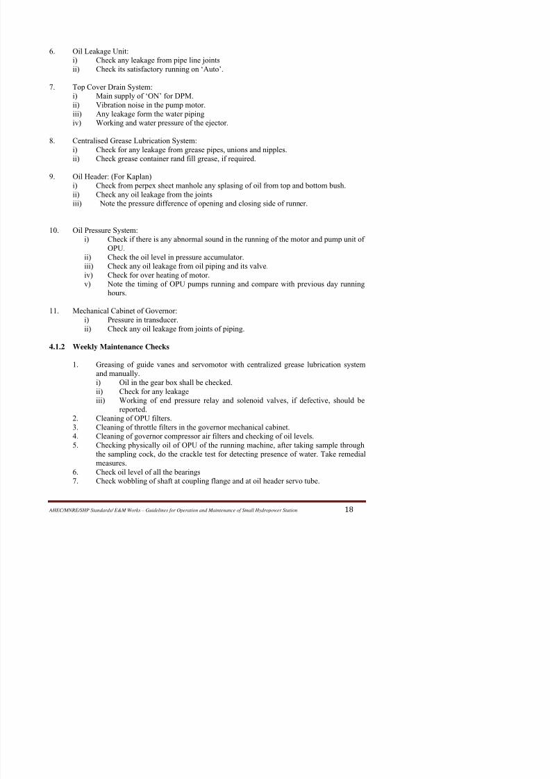
6. Oil Leakage Unit:
i) Check any leakage from pipe line joints
ii) Check its satisfactory running on ‘Auto’.
7. Top Cover Drain System:
i) Main supply of ‘ON’ for DPM.
ii) Vibration noise in the pump motor.
iii) Any leakage form the water piping
iv) Working and water pressure of the ejector.
8. Centralised Grease Lubrication System:i) Check for any leakage from grease pipes, unions and nipples.
ii) Check grease container rand fill grease, if required.
9.
Oil Header: (For Kaplan)
i) Check from perpex sheet manhole any splasing of oil from top and bottom bush.
ii) Check any oil leakage from the joints
iii)
Note the pressure difference of opening and closing side of runner.
10. Oil Pressure System:
i)
Check if there is any abnormal sound in the running of the motor and pump unit of
OPU.
ii) Check the oil level in pressure accumulator.
iii) Check any oil leakage from oil piping and its valve.
iv)
Check for over heating of motor.v) Note the timing of OPU pumps running and compare with previous day running
hours.
11.
Mechanical Cabinet of Governor:
i) Pressure in transducer.
ii) Check any oil leakage from joints of piping.
4.1.2 Weekly Maintenance Checks
1. Greasing of guide vanes and servomotor with centralized grease lubrication system
and manually.
i) Oil in the gear box shall be checked.

8/11/2019 Guidelines for Operation and Maintenance of Small Hydropower Station
http://slidepdf.com/reader/full/guidelines-for-operation-and-maintenance-of-small-hydropower-station 24/100
4.1.3 Monthly Maintenance Checks
All the checks covered in weekly maintenance as above are carried out monthly also. Butwhile carrying out these checks more attention is paid and short shutdowns, if required, for
rectification are taken.
4.1.4 Annual Inspection and Maintenance of Hydro Turbine
After successful running of plant for about one year few weeks are required to be allotted to
inspect rotating parts, control equipment and measuring instrument setc. And analyse cause
of change in the performance charactersitcs, if any. Modify / repair / replace (whereverrequired) the worn out parts in order to prevent forced outages of machine at later date.
After every five years it is necessary to inspect the machine more critically for abnormalities
like fatigue defects for excessive wear and tear of some parts or any change in original
parameters / clearances etc. This exercise becomes very essential in cases where
performance level has been observed to have gone down in 5 years operation.
The checks for annual and five yearly maintenance designed for a hydropower station are
enlisted below:
1.
Foundation Parts:
i) Check condition of water path system. The damage due to cavitation and wear
to be rectified
ii) Check painting of spiral casing.
2.
Runner:i) Check the condition of the surfaces of the runner hub and the blades. The
damage due to cavitations & wear to be rectified by welding and grinding.
ii) Check the runner blade seals by pressurizing the system. Change seals if
necessary. No oil leakage is to be allowed (Kaplan only).
iii) Check the runner sealing for hermetic tightness, leakages of water in the
runner hub is not to be permitted (Kaplan only).
3. Guide Apparatus:
i)
Check the presence of rubber sealing cords and the tightness of the rubber
sealing between the adjacent guide vanes in fully dosed position of guide
apparatus.
ii)
Change oil in the regulating ring.
iii) Replace damaged shear pins.

8/11/2019 Guidelines for Operation and Maintenance of Small Hydropower Station
http://slidepdf.com/reader/full/guidelines-for-operation-and-maintenance-of-small-hydropower-station 25/100
5. Shaft Gland Seal and Air Seal:
i) Check the condition of rubbing surface of sealing rings. In case found
damaged change the same.ii) Check pipe lines and piping joints for any leakage if any, attend the same.
6. Emergency Slide Valve:
i)
Check the functioning of emergency slide valve and the condition of inner
surfaces.
ii) Swift return of the valve in its original position after emergency operation
should also be checked.
7. Centralised Grease Lubrication System:
i) Check satisfactory working of CGLS system.ii) Attend wherever fault is located.
8.
OPU:
i) Check and attend leakage from any valve or flanged joints etc.
ii)
Provide proper lubrication to the bearings of pump motor.
iii) Check filter and repair, if required.
iv) Clean oil sump, refill with centrifuged oil.
v)
Check setting of the float relays for proper sequence of operation of pumps.9.
Oil Header
i) Measure clearances of upper and lower bushes, if found increased get the
bushes replaced.
ii)
Clean the oil bath.
iii) Check the rubber cord fixed below the guide to check any oil dipping on the
exciter winding.
10. Oil Leakage Unit:
i)
Check satisfactory working on Auto as well as manual.ii) Clean the tank.
iii)
Check the pipeline joints and valve for leakage, attend wherever necessary.
11. Oil Cooling Unit:
i)
Check all the oil and water pipe lines for leakage and attend if necessary.
ii) Check satisfactory working of all cooling unit.
12. Governor Mechanical Cabinet:
i) Check filter and throttle if found damaged replace the same.
ii)
Attend leakage of oil through pipe line joints and valves.
iii) Check auto rod setting, if found disturbed; set the same.
iv) Alignment of feed back wire rope pulleys.

8/11/2019 Guidelines for Operation and Maintenance of Small Hydropower Station
http://slidepdf.com/reader/full/guidelines-for-operation-and-maintenance-of-small-hydropower-station 26/100
i) Desembly, inspection, cleaning, measurement of clearances, polishing of
guide pads, centering of shaft, reassembly, setting of clearances, filling of oil
sump with filtered water.ii) Check the temperature sensing device, if necessary, replace with new ones.
2.
Gland Seals and Isolating Air Inflated Seals:
Dessembly, inspection, cleaning and reassembly. Replacing of worn out rubber flaps
or carbon segments, if necessary.
3. Clean Water System:
Clean water pipes are dismantled, cleaned, reassembled with new gasket all the valvesare attended for any leakage etc.
4. Guide Vane Servomotor:
Dismentling for inspection and cleaning. Reassembling and replacing the seals with
new ones, if necessary.
5.
Guide Vanes Bush Housing :i)
Removing, cleaning and inspecting for wear and tear replacing with new ones
if found necessary. Replace seals, if necessary.
ii) Guide vanes are reconditioned.
6. Governor:
i) Cleaning and checking OPU pumps. Replace bushes, bearings etc. if found
worn out. Also attend pump motors.
ii)
Cleaning OPU sump and pressure accumulator and refill with filtered oil.iii) Attend oil pipeline flanges and valves for leakages.
iv)
Check setting of pressure switches installed for Auto operation for opu pumps.
v) Attend Governor Mechanical cabinet for leakages, loose links. Clean main and
pilot slide valves. Set Auto rod as per designs Alpha Beta setting may also be
checked in case of Kaplan turbine.
vi) Check electrical circuit. Tightening of all the connections should be done.
7.
Under Water Parts
i) Inspect condition of welded seams of penstock spiral crossing and draft tubes
rectify defects by welding and grinding. Penstock filling line valve should also
be checked and repaired.
ii) Cleaning and painting of penstock, spiral casing and draft tube liner.

8/11/2019 Guidelines for Operation and Maintenance of Small Hydropower Station
http://slidepdf.com/reader/full/guidelines-for-operation-and-maintenance-of-small-hydropower-station 27/100
v) In case the runner is found to be irreparable arrange to replace the same with
new one.
vi)
In case of Kaplan runner hydraulic test is also required to be done.
9. Turbine Auxiliaries
1.
DPM
i) Inspect top cover drain system; overhaul the ejector and drainage pumps.
ii) Check pipe lines and valves. Replace gaskets and other parts, if necessary.
10
Oil Cooling Uniti) Overhaul cooling pumps
ii)
Attend all the valves and pipe line for leakage
11
Centralised Grease lubrication System
i) Overhaul greasing pump.
ii) Check whole greasing lines. Replace worn out valves and gaskets etc.
iii) Check all the nylon pipes connected with the guide vane bushes. Replace
damaged pipes.
iv) Check that all the guide vanes are receiving grease properly.
12 Oil Leakage Unit
i) Check the oil leakage unit overhauls the pumps.
ii) Clean tank and check that float is properly working.
iii) Checking all the pipe liens and valves for leakages.
4.1.6 Major Maintenance Problems of Hydro Turbines
Some of the major problems encountered in the hydro turbines are damage in runners due to
erosion, cracking and cavitation due pressure pulsation in draft tube, instability of operation
at partial gate opening. Failure of turbine bearings, leakages of water through of turbine guide
bearings, leakage of water through guide vane seals and turbine gland seals, these problems
are discussed in detailed in the following paras.
A. Runner
1. Erosion due to silt

8/11/2019 Guidelines for Operation and Maintenance of Small Hydropower Station
http://slidepdf.com/reader/full/guidelines-for-operation-and-maintenance-of-small-hydropower-station 28/100
At surface power stations with open channels following measures of desilting are taken:
i) Silt extruders have been provided near under sluice gates of the barrage.
ii) About half a kilometer downstream of the head regulator a silt ejector has been
constructed in the bed of the power channel
iii) In some projects desilting basin is constructed.
iv) Forebay is also used as desilting basing with flushing conduits
2. Cavitation & Cracking of Runner
The problem of cracking of runner and Pelton buckets in few power stations has been
reported. This can be due to following reasons:
i) Faulty design
ii)
Poor metallurgy
iii) Metal fatigue
The cavitation phenomenon occurs due to the vaporization of flowing fluid in a zone of
excessive low pressure. Cavitation is inherent even in the best designed turbines and
cavitation damage occur under unfavourable operating conditions, limits of metal removal
have been specified beyond which cavitation becomes harmful and requires repair. To
minimize cavitation following steps are necessary:
i) Periodically (annually) inspect the runner and other turbine parts and take remedial
measures.
ii) Operate the machines as per guide lines given by manufacturers. The unit should not
be run below certain load to avoid cavitation pron zones.iii) At design stage itself, ensuring proper submergence use of cavitation resistant
material and adoption of optimize runner profile based on mode tests, cavitation can
effectively controlled.
iv)
As a result of draft tube pulsation and surges at no load or part gate opening excessive
nose, vibrations and cavitation is experienced. To minimize pulsation of draft tube
following measures must be taken:
-Air admission through air admission / vacuum braking valve installed at top cover.
-Provision of fins or flow splitter in draft tube to break the vortex flow.
-Provision of a byepass arrangement for releasing the pressure built up below the top
cover.
Normally the discharge side surface of buckets or blades, areas on the crown on the
throat ring and the tip of the blades and the upper portion of the draft tube liner are affected

8/11/2019 Guidelines for Operation and Maintenance of Small Hydropower Station
http://slidepdf.com/reader/full/guidelines-for-operation-and-maintenance-of-small-hydropower-station 29/100
iii) Preheating of the blade to about 60 °C is necessary.
iv) Avoid any localized excessive heating. It is achieved by welding for a short time in
any one particular area and then moving to a diametrically opposite area to continuewith the work.
v) The parent material about 70 to 75 mm. form the weld, should not be allowed to get
too hot to be touched with bare hand.
vi) Plenty of time should be allowed for the welded area to cool down since forced
cooling may cause distortion due to locked in stresses. Hot peening is also must.
vii) A close check should be made at least two to three times per day during the repair of
runner to runner chamber clearances.
viii)
After welding all the welded areas should be properly ground to match with thedesired profiled.
ix) Die penetration tests should once again be carried out to ensure crack free welding.
Rectification, if necessary, should be done.
If extensive welding on the runner is required, it will be desirable to do static as ell dynamic
balancing of the rotating parts ad stress relieving before recommissioning to prevent problem
of cracking of blades and excessive vibrations in machines.
B. Turbine Guide Bearing
A number of turbine guide bearing designs are in use. These may be classified as follows:
i) Plain water cooled bearing.
ii) Bath type with circular cooling turbines.
iv)
Bath type with cooling water tubes embedded in the pads.
v)
Grease lubricated bearing.
In the case of plain water cooled bearings, either ferrobestos or rubber lined pads are used
against a welded shaft sleeve. The ferrobestos lined bearing have given considerable trouble
at one of the power station and these had to be replaced by rubber lined pads.
Small dia cooling pipes embedded in bearing pads have a tendency to clog especially at the
time of high silt contents resulting in water starvation. Complaints of excessive oil splashing
have been received about the rotating bath type bearing. Grease lubrication bearings have a
tendency to clog when in contact with the water and it is very essential to use grease with
the right type of properties.
A number of cases of turbine guide bearing failures have come to notice. These are:
8/11/2019 Guidelines for Operation and Maintenance of Small Hydropower Station
http://slidepdf.com/reader/full/guidelines-for-operation-and-maintenance-of-small-hydropower-station 30/100
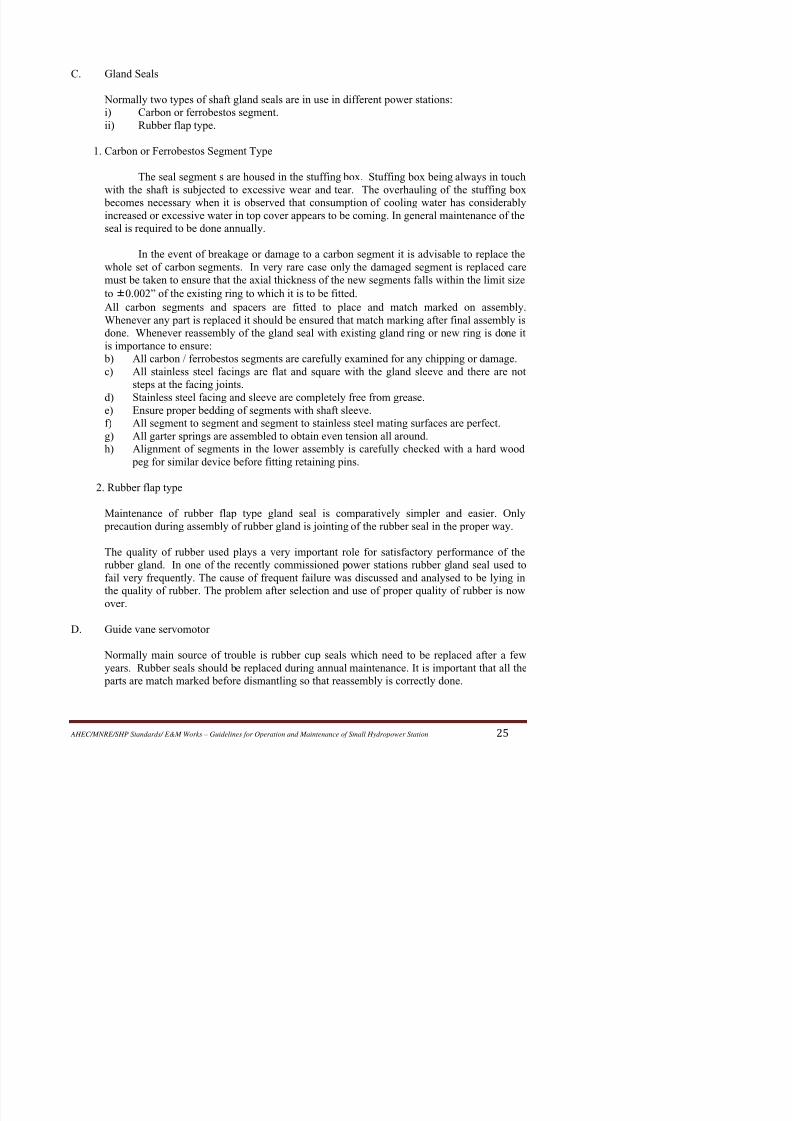
C. Gland Seals
Normally two types of shaft gland seals are in use in different power stations:i) Carbon or ferrobestos segment.
ii) Rubber flap type.
1. Carbon or Ferrobestos Segment Type
The seal segment s are housed in the stuffing box. Stuffing box being always in touch
with the shaft is subjected to excessive wear and tear. The overhauling of the stuffing box
becomes necessary when it is observed that consumption of cooling water has considerablyincreased or excessive water in top cover appears to be coming. In general maintenance of the
seal is required to be done annually.
In the event of breakage or damage to a carbon segment it is advisable to replace the
whole set of carbon segments. In very rare case only the damaged segment is replaced care
must be taken to ensure that the axial thickness of the new segments falls within the limit size
to ±0.002” of the existing ring to which it is to be fitted.
All carbon segments and spacers are fitted to place and match marked on assembly.
Whenever any part is replaced it should be ensured that match marking after final assembly is
done. Whenever reassembly of the gland seal with existing gland ring or new ring is done it
is importance to ensure:
b) All carbon / ferrobestos segments are carefully examined for any chipping or damage.
c) All stainless steel facings are flat and square with the gland sleeve and there are not
steps at the facing joints.
d)
Stainless steel facing and sleeve are completely free from grease.e) Ensure proper bedding of segments with shaft sleeve.
f) All segment to segment and segment to stainless steel mating surfaces are perfect.
g) All garter springs are assembled to obtain even tension all around.
h) Alignment of segments in the lower assembly is carefully checked with a hard wood
peg for similar device before fitting retaining pins.
2. Rubber flap type
Maintenance of rubber flap type gland seal is comparatively simpler and easier. Only
precaution during assembly of rubber gland is jointing of the rubber seal in the proper way.
The quality of rubber used plays a very important role for satisfactory performance of the
8/11/2019 Guidelines for Operation and Maintenance of Small Hydropower Station
http://slidepdf.com/reader/full/guidelines-for-operation-and-maintenance-of-small-hydropower-station 31/100
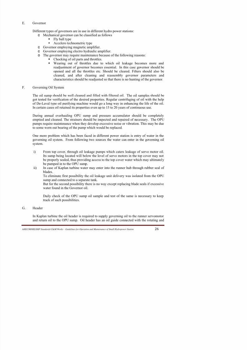
E. Governor
Different types of governors are in use in different hydro power stations:o Mechanical governor can be classified as follows
Fly ball type
Accelero technometric type
o Governor employing magnetic amplifier.
o Governor employing electro hydraulic amplifier.
o The governor may require maintenance because of the following reasons:
Chocking of oil parts and throttles.
Wearing out of throttles due to which oil leakage becomes more andreadjustment of governor becomes essential. In this case governor should be
opened and all the throttles etc. Should be cleared. Filters should also be
cleaned, and after cleaning and reassembly governor parameters and
characteristics should be readjusted so that there is no hunting of the governor.
F. Governing Oil System
The oil sump should be well cleaned and filled with filtered oil. The oil samples should be
got tested for verification of the desired properties. Regular centrifuging of oil with the help
of De-Laval type oil purifying machine would go a long way in enhancing the life of the oil.
In certain cases oil retained its properties even up to 15 to 20 years of continuous use.
During annual overhauling OPU sump and pressure accumulator should be completely
emptied and cleaned. The strainers should be inspected and repaired of necessary. The OPU
pumps require maintenance when they develop excessive noise or vibration. This may be dueto some worn out bearing of the pump which would be replaced.
One more problem which has been faced in different power station is entry of water in the
governing oil system. From following two sources the water can enter in the governing oil
system.
i) From top cover, through oil leakage pumps which caters leakage of servo motor oil.
Its sump being located will below the level of servo motors in the top cover may not be properly sealed, thus providing access to the top cover water which may ultimately
be pumped in to the OPU sump.
ii) In case of Kaplan turbine water may enter into the runner hub through rubber seal of
blades.

8/11/2019 Guidelines for Operation and Maintenance of Small Hydropower Station
http://slidepdf.com/reader/full/guidelines-for-operation-and-maintenance-of-small-hydropower-station 32/100
servo tube. The servo tube has ports to receive return oil to the pipes coming form OPU
sump. This tube is guided by three sets of bushes in the oil tube. Due to run out of the shaft
these bushes has to press the servo tube. Failure of these had been very frequent in one of the power station.
Monitoring of wobbling of the servo tube with help of dial indicator may provide a guide line
and save the bushes from further wearing. Remedial measures to reduce run out of the servo
tube must be taken at this stage.
At the time of assembly of various parts of header proper match marking and dowelling is
essential so that reassembly may be correctly done.
4.2 PREVENTIVE MAINTENANCE OF HYDRO GENERATOR
Preventive maintenance ensures a long trouble free operation of the generator. Given in the
following table are the recommended daily, monthly, once in 3 months, half yearly & yearly
maintenance checks to be conducted on the generator. While it is appreciated that it is not always
possible to rightly follow this schedule due to generator loading constraints, the recommendation
given may be taken as a guide line and these may be altered slightly, based on the past experience.
Sl. No. Description Periodicity Remarks
1.00 Stator:
1.01 Temperature record on log sheet for core and
winding, hot and cold air temperature
Hourly
1.02 Visual inspection of the overhang parts of the
stator winding.
Once in 3
months1.03 Checking the fixing of winding, condition of
winding joints with bus bars etc.
Once in 3
months
1.04 Clean the winding with dry & clean
compressed air (2 to 3 kg/cm2).
Once in 3
months
Cleaning to be done
such that the dust does
not collect in side
machine.
1.05 Check overhang parts of stator winding, bus bars, inner periphery of stator core (if
possible), parts of stator winding in slots
(specially at sector joint) binding & spacers
between the winding bars/ bandage rings.
Yearly
1 06 Check looseness of overhang busbars slot Yearly

8/11/2019 Guidelines for Operation and Maintenance of Small Hydropower Station
http://slidepdf.com/reader/full/guidelines-for-operation-and-maintenance-of-small-hydropower-station 33/100
Sl. No. Description Periodicity Remarks
to 3 kg/cm2).
1.12 After cleaning apply Red-gel coat on theoverhang. Yearly Not required during600 hrs. inspection.
1.13 In case of excessive wetting of stator winding
during conditions such as flooding, drying of
winding by passing current is not allowed
initially as electrolysis of water may take
place. Which is harmful to the winding.
As per
requirement
External heating
arrangement is to be
provided till wetness
is removed
2.00 ROTOR:
2.01 Check rotor winding and insulation details ofcurrent carrying leads.
Once in 3months
2.02 Check the condition of interpolar connectins Once in 3
months
2.03 Check the condition of damper winding. Once in 3
months
2.04 Check the locking of pole wedges. If required
carryout additional wedging.
Yearly
2.05 Check locking of rim wedges Yearly In case the wedges are
loose contact
manufacturer before
attempting any
rectification.
2.06 Check the gaps of spider arms, brake track. Yearly
2.07 Check tightening & proper locking of all
fasteners.
Yearly
2.08 Clean rotor from dust by blowing
compressed air free from moisture (2 to 3
kg/cm2).
Yearly
2.09 Measure D.C. resistance and IR value of
rotor winding.
Yearly Keep a record
2.10 Check the pole coils for interturn fault. Yearly Not required during
600 hrs. inspection.3.00 Slipring & Brush Rocker
3.01 Check sparking. Every shift
3.02 Check pitting & Grooving of slipring Monthly In case of excessive
grooving rectify by
i di

8/11/2019 Guidelines for Operation and Maintenance of Small Hydropower Station
http://slidepdf.com/reader/full/guidelines-for-operation-and-maintenance-of-small-hydropower-station 34/100
Sl. No. Description Periodicity Remarks
used till it is not
possible to measure/adjust spring tension.
3.06 Check for absence of oil or its vapours
slipring area.
Every shift. Oil leakages, if any, to
be removed.
3.07 Check distance of brush holder from slipring
and keep it as specified in the drawing.
Monthly
3.08 New brushes to be used after bedding the
brushes. The brush should not be too
tight/loose inside the holder.
While replacing
3.09 Ensure use of same & recommended grade of
carbon brushes on one machine.
3.10 Check all fasteners of sliprings, brush rocker
& current carrying lead.
Once in 3
months
3.11 Check carbon brushes for absence of
spittings and severe wear & tear.
Monthly In case the damage is
excessive, replace
complete set.3.12 Inter change polarity of sliprings. Half yearly
3.13 Carryout thorough cleaning of slipring area.
Stop oil leakages in this area.
Half yearly
3.14 In case the original insulating enamel unit is
peeling off remove the balance enamel and
apply fresh enamel.
yearly While cleaning avoid
using insulating paint
removers.
3.15 Check wobbling at slip rings. At the time of
installation/during major
overhauling
4.00 Thrust Bearing
4.01 Measurement of temperatures of T.B. Pad &
Oil by RTD & TSD and record on log sheet.
Hourly
4.02 Check & record reading of oil level relay. Once in a shift
4.03 Analysis of oil from oil bath. Half yearly Record to be kept.4.04 Change of oil in T.B. oil bath When
centrifuging
doesn’t help in
improving its
lit t
8/11/2019 Guidelines for Operation and Maintenance of Small Hydropower Station
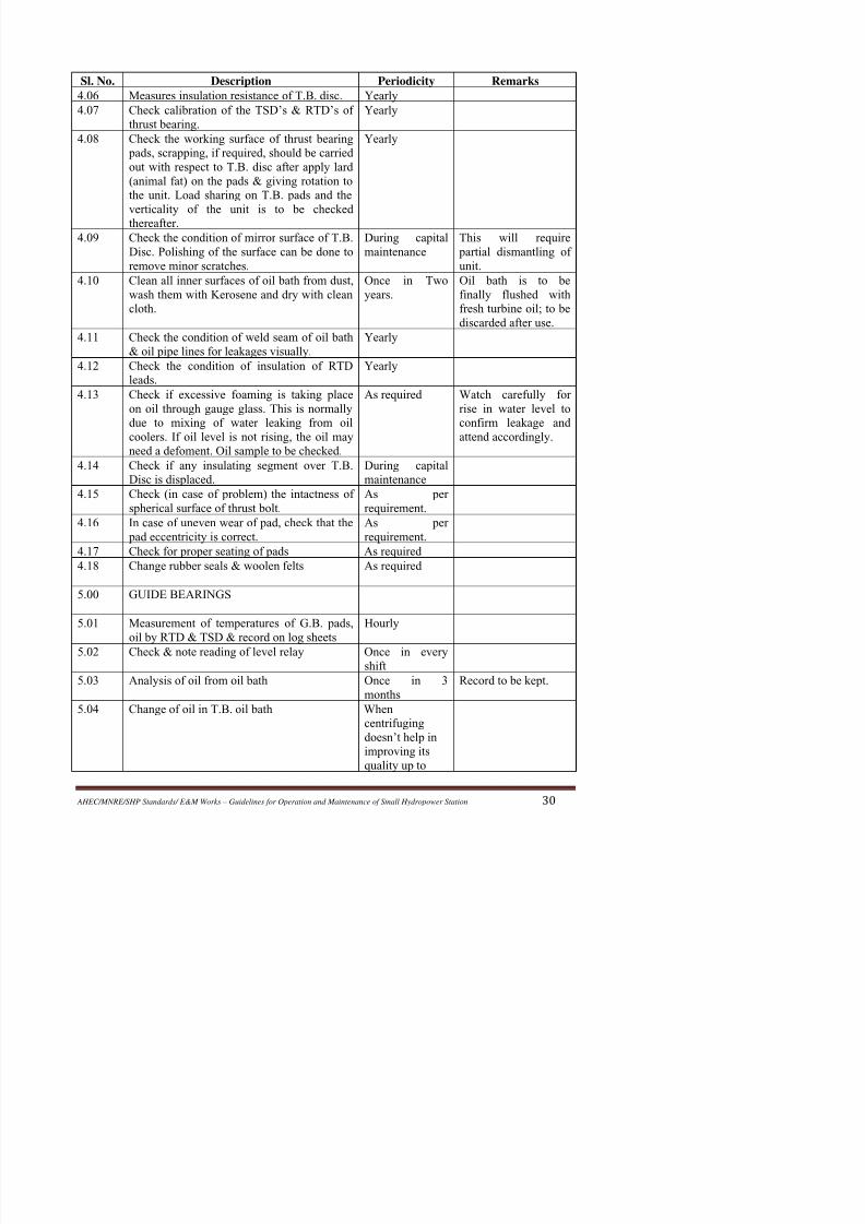
http://slidepdf.com/reader/full/guidelines-for-operation-and-maintenance-of-small-hydropower-station 35/100
Sl. No. Description Periodicity Remarks
4.06 Measures insulation resistance of T.B. disc. Yearly
4.07 Check calibration of the TSD’s & RTD’s ofthrust bearing. Yearly
4.08 Check the working surface of thrust bearing
pads, scrapping, if required, should be carried
out with respect to T.B. disc after apply lard
(animal fat) on the pads & giving rotation to
the unit. Load sharing on T.B. pads and the
verticality of the unit is to be checked
thereafter.
Yearly
4.09 Check the condition of mirror surface of T.B.
Disc. Polishing of the surface can be done to
remove minor scratches.
During capital
maintenance
This will require
partial dismantling of
unit.
4.10 Clean all inner surfaces of oil bath from dust,
wash them with Kerosene and dry with clean
cloth.
Once in Two
years.
Oil bath is to be
finally flushed with
fresh turbine oil; to be
discarded after use.4.11 Check the condition of weld seam of oil bath
& oil pipe lines for leakages visually.
Yearly
4.12 Check the condition of insulation of RTD
leads.
Yearly
4.13 Check if excessive foaming is taking place
on oil through gauge glass. This is normally
due to mixing of water leaking from oil
coolers. If oil level is not rising, the oil mayneed a defoment. Oil sample to be checked.
As required Watch carefully for
rise in water level to
confirm leakage and
attend accordingly.
4.14 Check if any insulating segment over T.B.
Disc is displaced.
During capital
maintenance
4.15 Check (in case of problem) the intactness of
spherical surface of thrust bolt.
As per
requirement.
4.16 In case of uneven wear of pad, check that the
pad eccentricity is correct.
As per
requirement.4.17 Check for proper seating of pads As required
4.18 Change rubber seals & woolen felts As required
5.00 GUIDE BEARINGS

8/11/2019 Guidelines for Operation and Maintenance of Small Hydropower Station
http://slidepdf.com/reader/full/guidelines-for-operation-and-maintenance-of-small-hydropower-station 36/100
Sl. No. Description Periodicity Remarks
acceptable
values5.05 Measures insulation resistance of G.B. pads. Yearly
5.06 Check calibration of TSD’s & RTDs of of
G.B.
Yearly
5.07 Prior to removal of pads, measure and record
guide bearing clearances.
As per
requirement
To be readjusted if
required, during
reinstallation
5.08 Check each pad for:
i)
Absence of scratch marks. Scrapping to be done with respect to the journal, if
required
ii) Heavy damage on babbit surface of pads
– full set be replaced from spares. The
spares set tot be scrapped with respect to
it’s respective journal surface by giving
rotation to the unit.
Yearly
5.09 Check the centering of the unit vis-à-vis the
labyrinth/runner chamber of turbine.
Yearly as per
requirement
5.10 Check the friction surface of the bearing
journal. Carryout its polishing, if necessary.
Yearly
5.11 Wash pads & journal with aviation petrol and
then carryout assembly of the guide bearing.
Yearly
5.12 Check the condition of welding seems of oil
bath & leakages from them and oil pipe liens.
Yearly
5.13 Clean all inner surfaces of oil bath from dust,
wash them with Kerosene and dry with clean
cloth.
Once in two
years
Oil bath is to be
finally flushed with
fresh turbine oil; to be
discarded after use.
5.14 Change rubber seals and woolen felts. As required
5.15 Check operation of the level relay and its
calibrations.
Yearly
5.16 Check welding of pad support block with oil
bath.
Yearly
5.17 Check looseness of pad and pad support
bolts.
Yearly
5 18 Ch k diti f d i l ti Y l

8/11/2019 Guidelines for Operation and Maintenance of Small Hydropower Station
http://slidepdf.com/reader/full/guidelines-for-operation-and-maintenance-of-small-hydropower-station 37/100
8/11/2019 Guidelines for Operation and Maintenance of Small Hydropower Station
http://slidepdf.com/reader/full/guidelines-for-operation-and-maintenance-of-small-hydropower-station 38/100
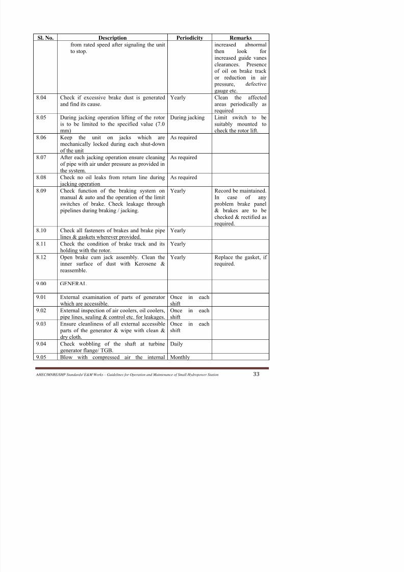
Sl. No. Description Periodicity Remarks
from rated speed after signaling the unit
to stop.
increased abnormal
then look forincreased guide vanes
clearances. Presence
of oil on brake track
or reduction in air
pressure, defective
gauge etc.
8.04 Check if excessive brake dust is generated
and find its cause.
Yearly Clean the affected
areas periodically asrequired
8.05 During jacking operation lifting of the rotor
is to be limited to the specified value (7.0
mm)
During jacking Limit switch to be
suitably mounted to
check the rotor lift.
8.06 Keep the unit on jacks which are
mechanically locked during each shut-down
of the unit
As required
8.07 After each jacking operation ensure cleaning
of pipe with air under pressure as provided in
the system.
As required
8.08 Check no oil leaks from return line during
jacking operation
As required
8.09 Check function of the braking system on
manual & auto and the operation of the limit
switches of brake. Check leakage through pipelines during braking / jacking.
Yearly Record be maintained.
In case of any
problem brake panel& brakes are to be
checked & rectified as
required.
8.10 Check all fasteners of brakes and brake pipe
lines & gaskets wherever provided.
Yearly
8.11 Check the condition of brake track and its
holding with the rotor.
Yearly
8.12 Open brake cum jack assembly. Clean the
inner surface of dust with Kerosene &
reassemble.
Yearly Replace the gasket, if
required.
9 00 GENERAL

8/11/2019 Guidelines for Operation and Maintenance of Small Hydropower Station
http://slidepdf.com/reader/full/guidelines-for-operation-and-maintenance-of-small-hydropower-station 39/100
Sl. No. Description Periodicity Remarks
surface of the generator.
9.06 External inspection of current carrying leadsPMG, Bus Bars, Terminal Blocks, Panels
edc.
Monthly To be cleaned ifnecessary
9.07 Check the condition of lighting inside the
barrel
Monthly
9.08 Check the recordings of lighting inside
original results.
Daily Reasons for variance
to be investigated
9.09 Check for proper cleaning of sliprings. As per
requirements9.10 Check the vibrations at TGB, UGB & LBG
predetermined points.
Yearly
9.11 Check connections of current carrying leads
& cables. Tighten the bolts, if required, after
removing the insulation.
Yearly
9.12 Check the calibration of Electrical measuring
instruments i.e. voltmeter, ammeter, Active/Reactive Power meter. Frequency meter, P.F.
meter for Stator output, Voltmeter &
Ammeter in Field winding circuit, energy
meter etc.
Yearly
9.13 Check the Sensitivity & Stability of
Generator Electrical Protection scheme.
Yearly
9.14 Check the working of Fire Extinguishing
(CO2) system without actually releasing theCO2) gas on manual and on auto operation as
per the instructions provided in O&M manual
of the Fire Extinguishing System provided by
its supplier.
Yearly
9.15 Check the characteristics of Static Excitation
system in both auto & manual mode and
sensitivity of various limits.
As specified in
its O&M
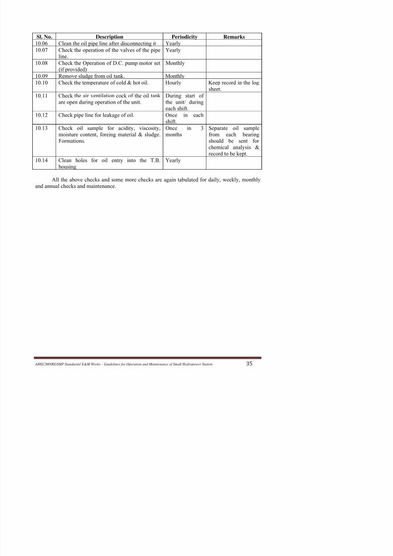
manual.10.00 OIL PIPE LINE/ EXTERNAL OIL
COOLING SYSTEM (If applicable)
10.01 Check oil pressure at the pump across the
filter & point of entry to the bearing.
Every shift Record is to be
maintained.
10 02 Ch k th ti f th l t i l t t M thl
8/11/2019 Guidelines for Operation and Maintenance of Small Hydropower Station
http://slidepdf.com/reader/full/guidelines-for-operation-and-maintenance-of-small-hydropower-station 40/100
Sl. No. Description Periodicity Remarks
10.06 Clean the oil pipe line after disconnecting it Yearly
10.07 Check the operation of the valves of the pipeline. Yearly
10.08 Check the Operation of D.C. pump motor set
(if provided)
Monthly
10.09 Remove sludge from oil tank. Monthly
10.10 Check the temperature of cold & hot oil. Hourly Keep record in the log
sheet.
10.11 Check the air ventilation cock of the oil tank
are open during operation of the unit.
During start of
the unit/ duringeach shift.
10.12 Check pipe line for leakage of oil. Once in each
shift.
10.13 Check oil sample for acidity, viscosity,
moisture content, foreing material & sludge.
Formations.
Once in 3
months
Separate oil sample
from each bearing
should be sent for
chemical analysis &record to be kept.
10.14 Clean holes for oil entry into the T.B.
housing
Yearly
All the above checks and some more checks are again tabulated for daily, weekly, monthly
and annual checks and maintenance.

8/11/2019 Guidelines for Operation and Maintenance of Small Hydropower Station
http://slidepdf.com/reader/full/guidelines-for-operation-and-maintenance-of-small-hydropower-station 41/100
8/11/2019 Guidelines for Operation and Maintenance of Small Hydropower Station
http://slidepdf.com/reader/full/guidelines-for-operation-and-maintenance-of-small-hydropower-station 42/100
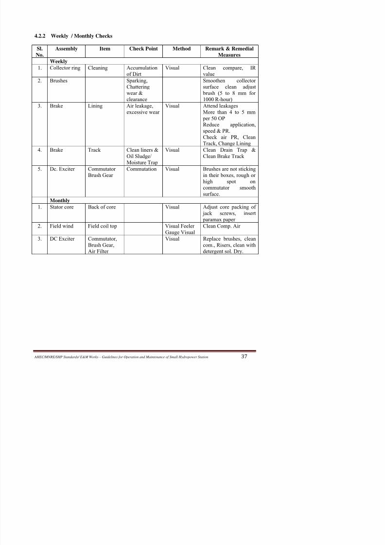
4.2.2 Weekly / Monthly Checks
Sl.
No.
Assembly Item Check Point Method Remark & Remedial
Measures
Weekly
1. Collector ring Cleaning Accumulation
of Dirt
Visual Clean compare, IR
value
2. Brushes Sparking,
Chattering
wear &
clearance
Smoothen collector
surface clean adjust
brush (5 to 8 mm for
1000 R-hour)3. Brake Lining Air leakage,
excessive wear
Visual Attend leakages
More than 4 to 5 mm
per 50 OP
Reduce application,
speed & PR.
Check air PR, Clean
Track, Change Lining
4. Brake Track Clean liners &
Oil Sludge/
Moisture Trap
Visual Clean Drain Trap &
Clean Brake Track
5. Dc. Exciter Commutator
Brush Gear
Commutation Visual Brushes are not sticking
in their boxes, rough or
high spot on
commutator smooth
surface.Monthly
1. Stator core Back of core Visual Adjust core packing of
jack screws, insert
paramax paper
2. Field wind Field coil top Visual Feeler
Gauge Visual
Clean Comp. Air
3. DC Exciter Commutator,
Brush Gear,
Air Filter
Visual Replace brushes, clean
com., Risers, clean with
detergent sol. Dry.
8/11/2019 Guidelines for Operation and Maintenance of Small Hydropower Station
http://slidepdf.com/reader/full/guidelines-for-operation-and-maintenance-of-small-hydropower-station 43/100
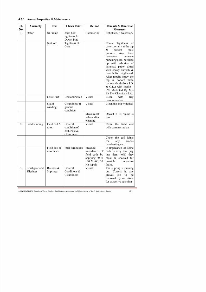
4.2.3 Annual Inspection & Maintenance
Sl.
No.
Assembly Item Check Point Method Remark & Remedial
Measures
1. Stator (i) Frame Joint bolt
tightness &
Dowel Pins
Hammering Retighten, if Necessary
(ii) Core Tightness of
Core
Check Tightness of
core specially at the top
& bottom most
packets. Any locallooseness between
punchings can be filled
up with asbestos of
paramax paper glued
with epoxy varnish &
core bolts retightened.
After repairs spray the
top & bottom three
packets (both from I.D.
& O.D.) with loctite –
290 Marketed By M/s
Fit Tite Chemicals Ltd.
Core Duct Contamination Visual Clean with Dry
compressed air
Statorwinding
Cleanliness &general
condition
Visual Clean the end windings
Measure IR
values after
cleaning
Dryout if IR Value is
low
2. Field winding Field coil &
rotor
General
condition of
coil, Pole &
cleanliness
Visual Clean the field coil
with compressed air
Check the coil joints
for any cracks
overheating etc

8/11/2019 Guidelines for Operation and Maintenance of Small Hydropower Station
http://slidepdf.com/reader/full/guidelines-for-operation-and-maintenance-of-small-hydropower-station 44/100
Sl.
No.
Assembly Item Check Point Method Remark & Remedial
Measures
4. DC exciter Core &
Winding
Accumulation
of dust
Visual For cleaning the exciter
Note: For cleaning stator ducts, stator winding, field coils, rotor leads, brushgear, PMG and
DC Exciter, Use cleaning agents as recommended by manufacturer
5. Bearings Top &
Bottom
Guide
Bearing
Pads
Clearance Feeler Gauge Check guide bearing
pad clearance. If pad
clearance have to be
reset the shaft must be
centered first.Examine the condition
of guide pads and any
slight scouring marks
can be attended by
water emery paper
(GR-400)
6. Air coolers Coolers
tubes
Clean inside and
outside of air cooler
tubes
Checks for any tube
leakage by pressurizing
to a pressure slightly
more than maximum
expected working
pressure.7. Oil coolers Coolers
tubes
Clean inside & outside
of oil
Check for any tube
leakage by pressurizing
to a pressure slightly
more than maximum
expected working
pressure.8. HS Lub.
System
HS Lub
Motor HP
Hose
Assembly
Inspect bearing &
Grease, if necessary
check the condition of
the hoses & if
8/11/2019 Guidelines for Operation and Maintenance of Small Hydropower Station
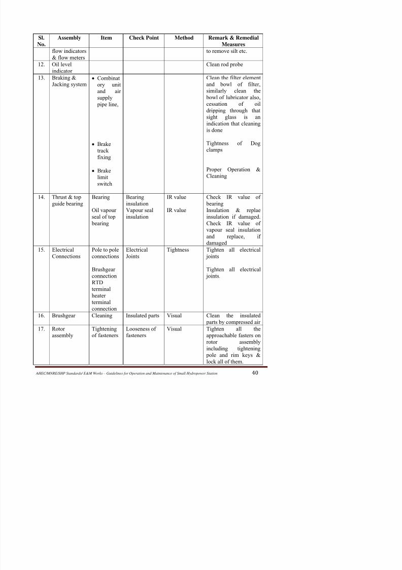
http://slidepdf.com/reader/full/guidelines-for-operation-and-maintenance-of-small-hydropower-station 45/100
Sl.
No.
Assembly Item Check Point Method Remark & Remedial
Measures
flow indicators
& flow meters
to remove silt etc.
12. Oil level
indicator
Clean rod probe
13. Braking &
Jacking system• Combinat
ory unit
and air
supply
pipe line,
• Brake
track
fixing
• Brake
limit
switch
Clean the filter element
and bowl of filter,
similarly clean the
bowl of lubricator also,
cessation of oildripping through that
sight glass is an
indication that cleaning
is done
Tightness of Dog
clamps
Proper Operation &
Cleaning
14. Thrust & top
guide bearing
Bearing
Oil vapour
seal of top
bearing
Bearing
insulationVapour seal
insulation
IR value
IR value
Check IR value of
bearingInsulation & replae
insulation if damaged.
Check IR value of
vapour seal insulation
and replace, if
damaged
15. Electrical
Connections
Pole to pole
connections
Brushgear
connection
RTD
Electrical
Joints
Tightness Tighten all electrical
joints
Tighten all electrical
joints.
8/11/2019 Guidelines for Operation and Maintenance of Small Hydropower Station
http://slidepdf.com/reader/full/guidelines-for-operation-and-maintenance-of-small-hydropower-station 46/100
Sl.
No.
Assembly Item Check Point Method Remark & Remedial
Measures
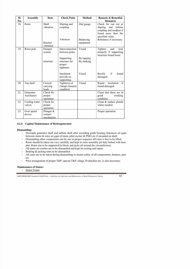
18. Rotor Shaft
vibration
Bracket
vibration
Slipring and
coupling
Vibration
Dial gauge
Balancing
equipment
Check for run out at
slipring and turbine
coupling and readjust if
found more than the
specified value.
Rebalance if necessary
19. Rotor pole Dampersystem
structure
Interconnection between poles
Supporting
structure for
proper
tightness
Insulation provide on
supporting
Visual
By tapping
By shaking
Visual
Tighten and lock properly if supporting
structure found loose.
Rectify if founddamaged.
20. Top shaft Current
carrying
leads
Tightness of
clamps General
condition
Visual Repair insulation if
found damaged
21. Generator
Auxiliaries
Check for
properoperation
Clean that these are in
good workingcondition
22. Cooling water
valves
Check for
proper
operation
Clean & replace glands
where needed.
23. Over speed
device
Plunger &
contact
mechanism
Proper operation
4.2.4 Capital Maintenance of Hydrogenerator
Dismantling:
- Decouple generator shaft and turbine shaft after recording guide bearing clearances air gaps
8/11/2019 Guidelines for Operation and Maintenance of Small Hydropower Station
http://slidepdf.com/reader/full/guidelines-for-operation-and-maintenance-of-small-hydropower-station 47/100
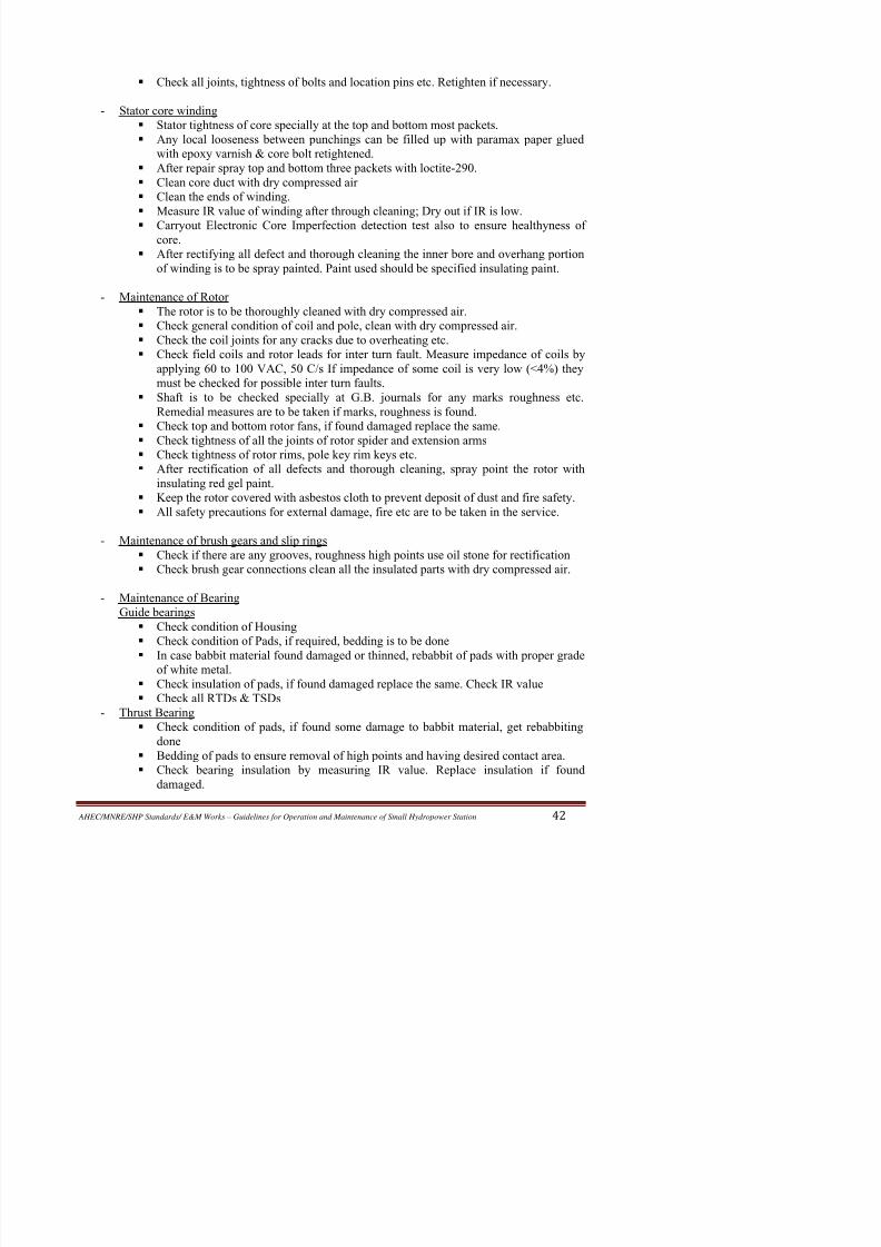
Check all joints, tightness of bolts and location pins etc. Retighten if necessary.
- Stator core winding
Stator tightness of core specially at the top and bottom most packets. Any local looseness between punchings can be filled up with paramax paper glued
with epoxy varnish & core bolt retightened.
After repair spray top and bottom three packets with loctite-290.
Clean core duct with dry compressed air
Clean the ends of winding.
Measure IR value of winding after through cleaning; Dry out if IR is low.
Carryout Electronic Core Imperfection detection test also to ensure healthyness ofcore.
After rectifying all defect and thorough cleaning the inner bore and overhang portion
of winding is to be spray painted. Paint used should be specified insulating paint.
- Maintenance of Rotor
The rotor is to be thoroughly cleaned with dry compressed air.
Check general condition of coil and pole, clean with dry compressed air.
Check the coil joints for any cracks due to overheating etc. Check field coils and rotor leads for inter turn fault. Measure impedance of coils by
applying 60 to 100 VAC, 50 C/s If impedance of some coil is very low (<4%) they
must be checked for possible inter turn faults.
Shaft is to be checked specially at G.B. journals for any marks roughness etc.
Remedial measures are to be taken if marks, roughness is found.
Check top and bottom rotor fans, if found damaged replace the same.
Check tightness of all the joints of rotor spider and extension arms
Check tightness of rotor rims, pole key rim keys etc.
After rectification of all defects and thorough cleaning, spray point the rotor with
insulating red gel paint.
Keep the rotor covered with asbestos cloth to prevent deposit of dust and fire safety.
All safety precautions for external damage, fire etc are to be taken in the service.
- Maintenance of brush gears and slip rings
Check if there are any grooves, roughness high points use oil stone for rectification Check brush gear connections clean all the insulated parts with dry compressed air.
-
Maintenance of Bearing
Guide bearings

8/11/2019 Guidelines for Operation and Maintenance of Small Hydropower Station
http://slidepdf.com/reader/full/guidelines-for-operation-and-maintenance-of-small-hydropower-station 48/100
Check insulation of vapour seal also and replace, if found damaged
Check condition of housing, pivot points of thrust bearing.
Check all pressure gauges, level indicator.
Check all RTDs & TSDs- Maintenance of Air Coolers
Clean inside and outside of air cooler tubes
Check for any tube leakage by pressurizing to a pressure slightly more than max.
expected working pressure
If more than 10% tubes are leaking change full set of tubes otherwise change only
leaking tubes
After repair paint the body of coolers.- Maintenance of Oil Coolers
Clean inside and outside of cooling tubes
Check for any tube leakage by pressurizing to a pressure slightly more than
maximum expected working
Replace full set of tubes if more than 10% of total tubes are leaking.
- Maintenance of H.S. Lub system
Inspect bearing and grease, if necessary
Check the condition of hoses, if necessary replace Check for any leakages and take remedial measures.
Check pressure gauges etc.
-
Maintenance of Flow relays, visual flow indicators and flow meter:
Inspect, clean water passages remove silt.
All defective meters are to be replace.
- Braking and jacking system:
Check brake units and clean inside outside of the unit
Change seals
Carry out hydraulic test
Clean the filters, bowl of lubricator
Check brake track, tighten dog clamps
Check working of brake limit switches.
Replace brake lining
- General checks
Check condition of current carrying leads. Check all water & oil valves for their proper working
Check general operational healthiness of all auxiliaries
Check proper working of overspeed device.
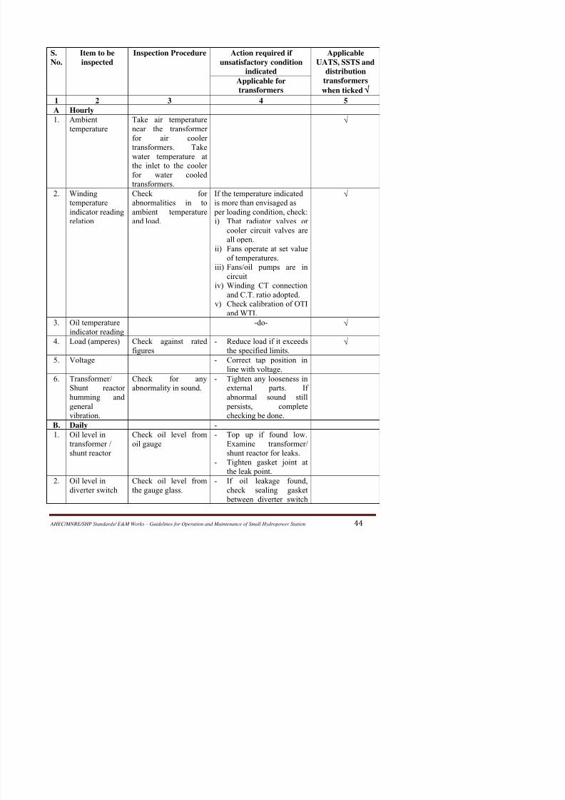
8/11/2019 Guidelines for Operation and Maintenance of Small Hydropower Station
http://slidepdf.com/reader/full/guidelines-for-operation-and-maintenance-of-small-hydropower-station 49/100
S.
No.
Item to be
inspected
Inspection Procedure Action required if
unsatisfactory condition
indicated
Applicable
UATS, SSTS and
distribution
transformers
when ticked
Applicable for
transformers
1 2 3 4 5
A Hourly
1. Ambient
temperature
Take air temperature
near the transformer
for air cooler
transformers. Takewater temperature at
the inlet to the cooler
for water cooled
transformers.
√
2. Winding
temperature
indicator reading
relation
Check for
abnormalities in to
ambient temperature
and load.
If the temperature indicated
is more than envisaged as
per loading condition, check:
i)
That radiator valves or
cooler circuit valves are
all open.
ii) Fans operate at set value
of temperatures.
iii) Fans/oil pumps are in
circuit
iv)
Winding CT connectionand C.T. ratio adopted.
v)
Check calibration of OTI
and WTI.
√
3. Oil temperature
indicator reading
-do- √
4. Load (amperes) Check against rated
figures
-
Reduce load if it exceeds
the specified limits.√
5. Voltage -
Correct tap position in
line with voltage.
6. Transformer/
Shunt reactor
humming and
Check for any
abnormality in sound.
- Tighten any looseness in
external parts. If
abnormal sound still

8/11/2019 Guidelines for Operation and Maintenance of Small Hydropower Station
http://slidepdf.com/reader/full/guidelines-for-operation-and-maintenance-of-small-hydropower-station 50/100
S.
No.
Item to be
inspected
Inspection Procedure Action required if
unsatisfactory condition
indicated
Applicable
UATS, SSTS and
distribution
transformers
when ticked
Applicable for
transformers
1 2 3 4 5
and transformer/ reactor
tank. Top up oil.
3. Oil level in
bushings
Check oil level from
the oil gauge of the
bushings in which oilremains separate from
the tank oil.
- If low, top up oil.
Examine bushing for any
oil leakage.
4. Pipe work and
accessories for
leakage
Check for oil leaks -
If leakages are observed,
tighten evenly the gasket
joints. Replace ‘O’ ring
or washer suitably.
Replace gasket if
needed.
5. Relief vent
diaphragm
Check for any crack - Replace if cracked /
broken. If broken, ensure
from other protections
provided that there is no
fault inside the
transformer / reactor.
6. Fans/ oil pumprunning
Check that fans / oil pump are running as
required.
-
Check connections. Iffound defective correct
them.
7. Oil & cooling
water flow.
Check oil and water
flow indicators.
- Check opening of valves
if restricted flow
observed.
C. Weekly
1. Leakage of
water into cooler
Check by opening the
end covers of the
cooler.
- Plug the tube leaking.
2. Operating
sequence of oil
d th
Change over from one
cooler to the other.
- Ensure proper change
over.

8/11/2019 Guidelines for Operation and Maintenance of Small Hydropower Station
http://slidepdf.com/reader/full/guidelines-for-operation-and-maintenance-of-small-hydropower-station 51/100
S.
No.
Item to be
inspected
Inspection Procedure Action required if
unsatisfactory condition
indicated
Applicable
UATS, SSTS and
distribution
transformers
when ticked
Applicable fortransformers
1 2 3 4 5
D. Monthly
1. Dehydrating
breather
i)
Check colour of
silica gel
ii) Check oil level in
the oil cup and
contamination of
oil visually.
iii)
Check that air
passages are free.
-
If more than half of
silica gel has turned
pink, change by spare
charge. The old chargemay be reactivated for
use again.
- Add oil, if required to
maintain oil level.
Replace oil if
contaminated.
-
Ensure air passages are
free.
2. Maximum
pointer of OTI
and WTI
Record the maximum
oil and winding
temperature readings
reached during the
month.
-
Check whether the
readings are within
permissible limits.
- Reset maximum pointer
of OTI and WTI.
3. Operation of
fans
In mixed cooling in
ONAN/ ONAF, if
temperature of oil has
been less than the fan
control setting
temperatures, operatethe fans manually to
check their running.
- Ensure smooth running
of fans.
E. Quarterly
1 Bushings Visual inspection for Clean dirt deposits If
S i A i i if A i

8/11/2019 Guidelines for Operation and Maintenance of Small Hydropower Station
http://slidepdf.com/reader/full/guidelines-for-operation-and-maintenance-of-small-hydropower-station 52/100
S.
No.
Item to be
inspected
Inspection Procedure Action required if
unsatisfactory condition
indicated
Applicable
UATS, SSTS and
distribution
transformers
when ticked
Applicable fortransformers
1 2 3 4 5
4. OLTC Examine contacts,
Check step by step
mechanism operation,
end position limit
switches and brakes.Check that wiring is
intact and all terminals
are tight.
- Replace all the worn out
and burnt contacts. Set
limit switches in
position. Clean / replace
brake shoe lining.Lubricate all bearing and
coupling points suitably.
Tighten terminals if
found loose.
5. Marshalling box Check wiring and that
terminals are tight.
- Tighten them if found
loose.
6. Oil in
transformer
Check for dielectric
strength and moisture
content
- Take suitable action to
restore quality of oil
7. Oil in diverter
switch
Check for dielectric
strength and moisture
content.
-do-
8. Insulation
resistance
Measure IR value
between windings and
to earth.
- Compare with previous
values. The comparison
should be done withthose values where
transformer/ reactor is
connected externally to
the line and bus ducts. If
the values are low,
measure IR values after
isolating it.
9. Oil bag sealing
arrangement
where provided.
Check presence of oil
outside the oil bag in
the conservator.
-
If oil is present check
leakage in the oil bag by
applying air pressure.
F. Half Yearly
1 Alarm trip and Check operation of In case of fa lt
S It t b I ti P d A ti i d if A li bl

8/11/2019 Guidelines for Operation and Maintenance of Small Hydropower Station
http://slidepdf.com/reader/full/guidelines-for-operation-and-maintenance-of-small-hydropower-station 53/100
S.
No.
Item to be
inspected
Inspection Procedure Action required if
unsatisfactory condition
indicated
Applicable
UATS, SSTS and
distribution
transformerswhen ticked
Applicable fortransformers
1 2 3 4 5
G. Yearly
1. Oil in
transformer
shunt/ reactor
i)
Complete testing of
oil.
ii) DGA of oil.
-
Filter to restore quality
or replace if the values
have reached discarding
limit.
2. Oil and winding
temperature
indicators.
i)
Calibrate and also
check differential
between WTI and
OTI by feeding
current to the WTI
pocket heating
element.
ii)
Check oil in the
pockets.
-
Adjust if found reading
incorrectly.
-
Replenish, if required.
3. Magnetic oil
level gauge and
prismatic level
indicator
i) Check oil level in
conservator by dip
stick method.
ii)
Clean the oil gaugeglass.
- If oil level indication is
not correct check the
float.
-
Replace glass if cracked.
4. Buchhloz Relay Mechanical inspection
i) Close valve
between buchholz
and conservator
and lower oil level.
ii) Check the
movement of floatsfor rise and fall.
iii) Check tightness of
mercury switches.
iv) Check the
- Buchholz contacts
should operate when oil
level comes below
buchholz relay level.
- Make the movement
smooth.
- Tighten clamps if loose.
- Check contacts if
abnormality found
S Item to be Inspection Procedure Action required if Applicable
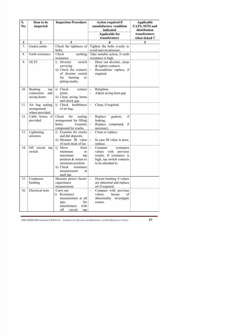
8/11/2019 Guidelines for Operation and Maintenance of Small Hydropower Station
http://slidepdf.com/reader/full/guidelines-for-operation-and-maintenance-of-small-hydropower-station 54/100
S.
No.
Item to be
inspected
Inspection Procedure Action required if
unsatisfactory condition
indicated
Applicable
UATS, SSTS and
distribution
transformerswhen ticked
Applicable fortransformers
1 2 3 4 5
7. Gasket joints Check the tightness of
bolts.
Tighten the bolts evenly to
avoid uneven pressure.
8. Earth resistance Check earthing
resistance
Take suitable action, if earth
resistance is high.
9. OLTC i)
Diverter switchservicing
ii) Check the contacts
of diverter switch
for burning or
pitting marks.
-
Draw out diverter, clean& tighten contacts.
- Recondition/ replace, if
required.
10. Bushing top
connectors and
arcing horns
i) Check contact
joints.
ii) Clean arcing horns
and check gap.
- Retighten.
-
Adjust arcing horn gap
11. Air bag sealing
arrangement
where provided.
i) Check healthiness
of air bag.
- Clean, if required.
12. Cable boxes, if
provided
Check for sealing
arrangement for fillingholes. Examine
compound for cracks.
- Replace gaskets, if
leaking.- Replace compound, if
necessary.
13. Lightening
arrestors
i) Examine for cracks
and dirt deposits.
ii) Measure IR value
of each stack of las.
- Clean or replace.
- In case IR value is poor,
replace.
14. Off circuit tap
switch
i) Move from
minimum to
maximum tap
position & return to
minimum position.
ii) Check resistance
- Compare resistance
values with previous
results. If resistance is
high, tap switch contacts
to be attended to.
S Item to be Inspection Procedure Action required if Applicable
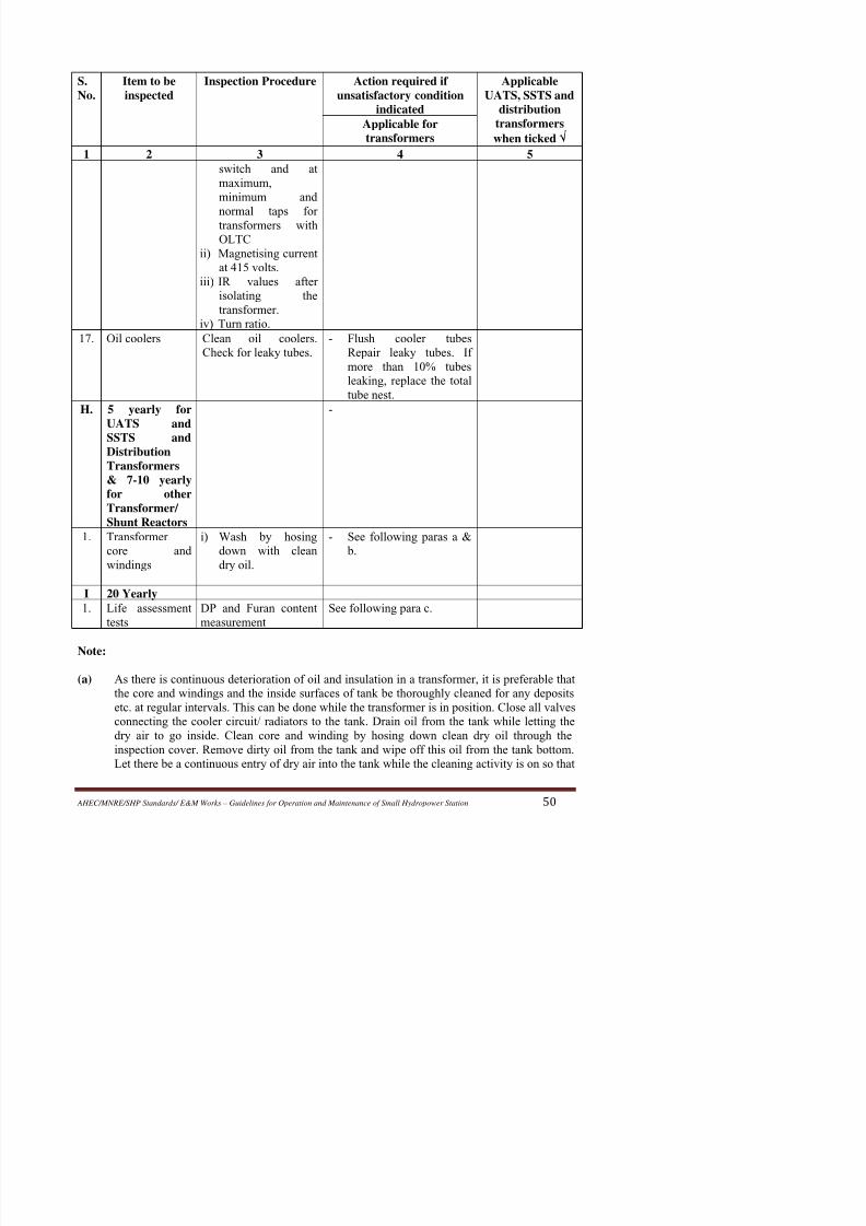
8/11/2019 Guidelines for Operation and Maintenance of Small Hydropower Station
http://slidepdf.com/reader/full/guidelines-for-operation-and-maintenance-of-small-hydropower-station 55/100
S.
No.
Item to be
inspected
Inspection Procedure Action required if
unsatisfactory condition
indicated
Applicable
UATS, SSTS and
distribution
transformerswhen ticked
Applicable fortransformers
1 2 3 4 5
switch and at
maximum,
minimum and
normal taps for
transformers withOLTC
ii) Magnetising current
at 415 volts.
iii) IR values after
isolating the
transformer.
iv)
Turn ratio.
17. Oil coolers Clean oil coolers.Check for leaky tubes.
-
Flush cooler tubesRepair leaky tubes. If
more than 10% tubes
leaking, replace the total
tube nest.
H. 5 yearly for
UATS and
SSTS andDistribution
Transformers
& 7-10 yearly
for other
Transformer/
Shunt Reactors
-
1. Transformer
core andwindings
i) Wash by hosing
down with cleandry oil.
- See following paras a &
b.
I 20 Yearly
1 Life assessment DP and Furan content See following para c
there is a minimum contact of the transformer core and windings with the atmospheric air

8/11/2019 Guidelines for Operation and Maintenance of Small Hydropower Station
http://slidepdf.com/reader/full/guidelines-for-operation-and-maintenance-of-small-hydropower-station 56/100
there is a minimum contact of the transformer core and windings with the atmospheric air.
Similarly drain oil from cooling circuit and radiators and fill dry clean oil.
(b) Whenever transformer windings are to be taken out due to any reason such as to repair a
damage, thorough washing due to sludge formation or for thorough inspection to locate afault as a result of DGA or some other tests, after carrying out the necessary work for which
the transformer was opened, do the following also:
(i) Tighten all coil clamping screws to remove looseness from the windings, if any.
(ii) Tighten all nuts and bolts whether metallic or made of insulating material on
mechanical and electrical joints.
(iii) Tighten core yoke bolts, core-clamping screws etc.
(c)
Under the normal operating condition transformer has an useful life of about 25-30 years.
This may vary considerably depending upon the overloads it has carried and the temperature
at which it has worked during its span of operation. Therefore for any future planning it may
be worth while to know well in advance the remanent life of the transformer in service. This
can be done by assessing extent of degradation of cellulosic paper through furan content in
transformer oil or / and degree of polymerization (DP) of paper. It is proposed to carry out
this study after a period of 20 years of service. After knowing the remanent life in a
transformer, the action can be planned in conjunction with life assessment studies ongenerating unit.
As these are comparatively new studies, the data are still being built and one should go by the
re-commendation of the Test Laboratory. However the following figures may serve as
guidelines.
Degree of Furan content
Polymerization ppm (mg/kg)
New transformer 800-950 Negligible
Nearing end of life 150-200 10
4.4 PREVANTIVE MAINTENANCE OF HYDROMECHANICAL EQUIPMENT

8/11/2019 Guidelines for Operation and Maintenance of Small Hydropower Station
http://slidepdf.com/reader/full/guidelines-for-operation-and-maintenance-of-small-hydropower-station 57/100
4.4 PREVANTIVE MAINTENANCE OF HYDROMECHANICAL EQUIPMENT
4.4.1 Maintenance of Intake Gates
The maintenance work shall included
• Cleaning up
• Adjustment
• Lubrication with recommended lubricants & methods
• Replacement of Defective parts
• Repair of damaged parts
•
Recoating of damaged coat on ropes• Recording details of all work carried out with date & time.
Inspection and checks
Daily inspection should be carried out by gate operator to ensure:
• Proper oiling and greasing wherever required
• Tightening of loosened parts tightening contacts in electrical system
•
Check of ropes and hoisting arrangement.
• Checking general condition of gates and gate grooves wheels etc.
Periodic inspection (half yearly or annual)
• Dissemble and check all components for any damage.
• Rectify damages or replace worn out irreparable components.
• All safety precautions eg taking proper shut down installing safety tags, red flags etc.
are must, when any work is being on gates.
•
Before taking up work on gates, stop log gates must be lowered in the groove meant
for the same and plug all leakages through these.
Lubrication of gate parts:
• Servogem EPI (IOC) or (equivalent of other brand)
- Rope drum shaft for all hoisting unit (once a month)
- Plumber blocks for all hoisting units fitted with bush bearing (once in
two months)- Coupling for transmission shaft (once in two months)
- Plumber blocks for manual operation (once in three months)
• Servogem – 3 (IOC) or (equivalent of other brand)
-
Spherical roller bearings for gate wheels (once in 2 months)
Problem in electrical circuit and checks

8/11/2019 Guidelines for Operation and Maintenance of Small Hydropower Station
http://slidepdf.com/reader/full/guidelines-for-operation-and-maintenance-of-small-hydropower-station 58/100
• No supply at control panel inspite of turning on main switch – check fuses.
•
Incoming supply healthy but volt meter not showing – check fuses of voltmeter circuit• Motor is running even after pressing stop push button
• Immediately put main switch off
• Check contacts of motor control contactor & push button contacts. If damaged replace
these
• Reset O/L relay before starting again
• O/L relay tripped
Check control fuseIf fuse OK check control transformer
• Gate is creeping down & restoration has failed indicating lamp is glowing but alarm
not ringing
• Check position to toggle switch (it should be in reset position)
• Indication of lamps are not glowing.
• Check by pressing lamp test push button replace bulbs, if found fused.
4.4.2 MAINTENANCE OF MAIN INLET VALVES
The turbine may have either a butterfly or spherical valve. This valve is used each
time the unit is shut down. Valve seats, seals, operating links, bearings, bushings, power
source and hydraulic links are the main primary maintenance concern.
The valve function should be verified periodically through test or normal frequent
operation.
Butterfly valves (head upto 120 m)
• Butter valves generally consists of a disc or lattice mounted on a shaft that rotates in
cylindrical body
• Usually, the disc and lattice profile is contoured in the flow direction to provide a
smooth hydraulic flow and balance forces on the valve.• The disc is oriented parallel to the flow to minimize any restriction when opened and
at right angle to the flow to provide full closure
• Valve seals are on the circumference or in contact portion of the valve body
• These seals can be replaced or adjusted without removing the disc from the valve.
Spherical valves (for heads more than 120 m)
8/11/2019 Guidelines for Operation and Maintenance of Small Hydropower Station
http://slidepdf.com/reader/full/guidelines-for-operation-and-maintenance-of-small-hydropower-station 59/100
Spherical valves have a body shaped like hollow sphere with flanges or other
connection for mounting in a piping system.
The rotor, shaped like ball, has a cylindrical hole through its centre at right angles to
support shafts located on each side of valve. In open position with rotor opening parallel to
the flow direction, the valve offers an unrestricted flow with minimum disturbance to the
flow path. To close the valve, the valve rotor is turned to 90o from the axis of rotor opening.
Spherical valve has tendency to close for positions less than 50% opening which
facilitates emergency closing.
Moveable seals reduce valve leakage when the valve is closed. Mostly valves have
both upstream and downstream seal. The upstream seal is maintenance seal or emergency
seal, the down stream seal is working seal.
When valve is closed under full pressure, the upstream maintenance seal allows
replacement or maintenance of the working seal with out dewatering the penstock. Theupstream maintenance seals have positive mechanical locking to prevent accidental opening.
• Daily checks of operating system and remedial measure are must.
• Annual inspection and overhauling of mechanical seal after dewatering penstock is
must.
• Annual inspection and over hauling of operating seal is also essential.
• Annual overhauling of operating mechanism to ensure smoth working through out
year is also done.
• Annual overhauling of the valve rotor and other parts are also taken up as required.
Following Checks are also Essential
• Checking and attending leakages from Valve & dismantling joint.
•
Checking and attending oil leakages from Servomotor• Checking the operation of operating valves.
• Checking and attending the setting of Limit Switches & Operation of the same
• Checking and attending leakages of distributing valve
Ch ki h ki f h L b i h if
• Checking foundation bolts and nuts of valves & servomotor. Cleaning the bolts and
8/11/2019 Guidelines for Operation and Maintenance of Small Hydropower Station
http://slidepdf.com/reader/full/guidelines-for-operation-and-maintenance-of-small-hydropower-station 60/100
nuts etc.
• Checking servomotor piston and its collars & its gland packing
•
Checking hole of the servomotor cylinder• Checking the pins and bushes of servomotor & its air valve
• Checking the diapharms in the opening & closing circuit. Checking the opening &
closing times of the MIV.
4.4.3 MAINTENANCE OF DRAFT TUBE GATES
One, two or three bulk head gates are needed to close off the draft tube. These areusually cable suspended gravity gates and designed for balanced pressure closure. These are
usually dropped to close or lifted to open through hoisting arrangement having rope drums.
The main problem with sealing is due to debris in bottom seal area. For withdrawal of
gate/ equalizing pressure across the gates is done with byepass line valve located with in gate.
When machine are running these gates and hoist remains available for maintenance.
These should always remain in perfect condition for use during emergencies of power station.
During annual maintenance of the unit these gates are required to be lowered so that
dewatering of draft tube is possible. As such maintenance and overhaul of these gates are
taken up before starting annual maintenance of machine.
Lubrication of operating mechanism, its electrical system and coating all ropes meant
for lifting are of main concern for maintenance.
4.5 PROCEDURES FOR TYPICAL MAINTENANCE ACTIVITIESFig 1 to 4, 10, 12 to 14 have been taken from “Hydropower Stations: Generating Equipment and its
installation” by AN Goncharov
4.5.1 Reassembly of Vertical Hydro Unit
Sequence and Checks
• Lower all guide vanes.
• Trial assembly of Turbine runner for checking clearance between runner & runner
chamber (Kaplan) or static labyrinths & rotating labyrinths (Francis).
• After setting above clearances take out runner & shaft assy. to service by.
• Check rotor level, verticality of shaft and centering of shaft, correction of inclination

8/11/2019 Guidelines for Operation and Maintenance of Small Hydropower Station
http://slidepdf.com/reader/full/guidelines-for-operation-and-maintenance-of-small-hydropower-station 61/100
of shaft to be done at this stage itself (Alignment of generator).
• Couple Exciter shaft and assemble exciters, PMG, Oil header (Kaplan) etc. carry out
centering and setting.• Couple Turbine and Generator shaft properly as per procedure with help of torque
spanners. Ensure elongation of shaft bolts as per procedure.
• Checking unit alignment and taking corrective action by providing shims or
scrapping.
• Carry out load sharing of thrust pads.
• After completing assembly of machine and rotating the machine at no load check
balancing of rotor as per procedure. Balancing of the machine by adding calculatedweight on rotor spider and at proper angle, is done.
• Check vibrations of machine at no load, part load and full load, rectify defects if any.
4.5.2 Checking Concentricity of Labyrinth Seals
The upper and lower labyrinth rings must be concentric with the shaft to within 10%
of the gap on one side of the labyrinth seals. This is checked with a special device mounted
on the shaft (Fig. 1)

8/11/2019 Guidelines for Operation and Maintenance of Small Hydropower Station
http://slidepdf.com/reader/full/guidelines-for-operation-and-maintenance-of-small-hydropower-station 62/100
Fig 2: Balancing of Runner [Goncharov]
Calculation of displacement of centre of gravity of runner (h)
• The runner is placed on the device having horizontal steel plate-2 and sphere in
such a way that its centre of gravity lies well below the support point• A small weight is then placed on the lower band. This cause runner to resume a
new equilibrium position. The runner is thus titled. Equilibrium condition in this
case is equal to the moments acting on runner:
PR = Ga + Gµ (1)
P = weight applied in kg
R = radius at which wt. is placed
a = displacement of centre gravity of runner = h.b/R
μ = coefficient of rolling friction (0.001 to 0.0015)
Thus = h=μR
.
• To find centre of gravity of runner a weight is placed on lower band such that it is
sufficient for shifting the centre of gravity 1 to 2 mm. If magnitude ‘h’ is more it
can be adjusted with the help of adjusting screws. The following optimum value of‘h’ are recommended.
Runner wt. (Tons) 50 100 200
Height h (mm) 40 to 60 40 to 60 40 to 60
• Any possible inbalance of runner (due to inertia and friction between the
ti t f b l i d i ) i d t i d ft h b b ht

8/11/2019 Guidelines for Operation and Maintenance of Small Hydropower Station
http://slidepdf.com/reader/full/guidelines-for-operation-and-maintenance-of-small-hydropower-station 63/100
supporting parts of balancing device) is determined after runner has been brought
into equilibrium. This is done by placing weights at six to eight points of the band
circumference which cause the runner to assume equal inclinations. The magnitudeof the residual imbalance is equal to half of max and min weights needed for this.
The weight for this imbalance should be placed where the maximum weight is
placed.
• The balance weight should be reliably fixed on the runner in such a way that it is
protected from the action of flow. Best location for this is on the top of runner
beneath protective casing. The weight must be recalculated since the radius of
location has been changed.• Balancing must again be checked after weights have been fixed.
• Balancing is checked if minimum weight placed successively at two diametrically
opposite points tilt the runner by equal angle.
4.5.4 Checking Concentricity of Kaplan Runner
4.5.5 Hydraulic Testing of Runner (Kaplan) in Service Bay

8/11/2019 Guidelines for Operation and Maintenance of Small Hydropower Station
http://slidepdf.com/reader/full/guidelines-for-operation-and-maintenance-of-small-hydropower-station 64/100
Fig 4: Testing of Runner [Goncharov]
The correct assembly of the blade-actuating mechanism and the tightness of the
flanged joints of the runner and of its blade seals are checked after assembly. The tightness of
the runner is checked by hydraulic tests, while the correct assembly of the blade-actuating
mechanism is verified by rotating the blades.
The runner is hydraulically tested before the hub extension is fitted. This makes it
possible to check the tightness of the joint between hub body and hub bottom. Servomotor
cylinder cover (2) is placed on hub (1) before the test. A temporary cover is used if the
permanent cylinder cover is integral with the shaft flange. The openings in the cylinder over
for the connection with the shaft are blanked off with plugs (3). The gap between piston rod
and cylinder cover is closed with seal (4). Temporary connecting piece (5) with two unions is
placed on the piston rod. One union is connected to the opening in the rod and oil is delivered
through this opening into the servomotor cylinder beneath the piston. The second union is
connected to the opening in the rod, delivering oil into the cylinder above the piston. Theother ends of these unions are connected to pump (7) via hoses (6) (Fig. 4).
The hub is filled with oil through a plug in the bottom and pipe (8). The air escapes
through valves fitted on top and bottom of the servomotor cylinder. Oil delivery to the hub is
The blades are set to the no-load position by the oil pressure acting on the bottom of

8/11/2019 Guidelines for Operation and Maintenance of Small Hydropower Station
http://slidepdf.com/reader/full/guidelines-for-operation-and-maintenance-of-small-hydropower-station 65/100
The blades are set to the no load position by the oil pressure acting on the bottom of
the servomotor piston. Pressure on the top of this piston causes the blades to move into the
full-load position. This pressure is created by a pump. The smoothness of blade actuation istested at the same time, as are the blade travel and setting angle.
4.5.6 Centering and Alignment of Vertical Hydro Generator
• Alignment of rotor during installation is ensuring rubbing surface of thrust
bearings and the shaft mirror disc face are perpendicular to rotor centre.
• The procedure for rotor centering is as follows.
-
First centering of turbine shaft is checked since its flange and
centre line from reference bases centering of the generator rotor
- The generator is then provisionally centered relative to turbine
shaft.
- Then perpendicularity of rubbing surfaces of thrust bearing and
shaft flange face to the generator shaft centre line is checked.
- Then final alignment generator and turbine is done.
I. Procedure for alignment of unit
- Set elevation of thrust bearing
- Carry out rotational check of gen. shaft
- Calculate maximum throw and direction
- Minimize throw by scrapping insulated surface of mirror disc.
- Couple generator shaft with turbine shaft
-
Again check elevation & level of thrust bearing
-
Carry out rotational checks
- Find out run out at LGB & coupling flange
- If throw is still more again carry out scrapping of insulated surface of mirror
discs. Again check by rotation method and repeat till throw is with in limit
- Check throw and its direction at TGB
- Minimize throw by providing shim between coupling flange
-
Check throw at LGB, coupling flange and TGB, ensure these are with in limit.
This is necessary to establish unit axis.-
Check verticality of shaft with respect to duly leveled thrust bearing at correct
elevation.
II. Coupling of Shafts
B. Coupling

8/11/2019 Guidelines for Operation and Maintenance of Small Hydropower Station
http://slidepdf.com/reader/full/guidelines-for-operation-and-maintenance-of-small-hydropower-station 66/100
• Force of tightening of all bolts should be identical
•
Elongation of bolts, required to ensure proper tightening• Soundness of flange connection is checked by feeler gauge of 0.03 mm
thickness
III. Setting Elevation of Thrust Bearing
Elevation of upper bracket should be such that the runner is at desired level
Allowance for deflection of upper bracket due to weight of rotating parts and initialthrust should be taken into account.
Mount thrust bearing on upper bracket
Check perpendicularity of thrust collar with shaft
Set elevation of bearing, by providing shims under flexible support
IV. Rotational Checks
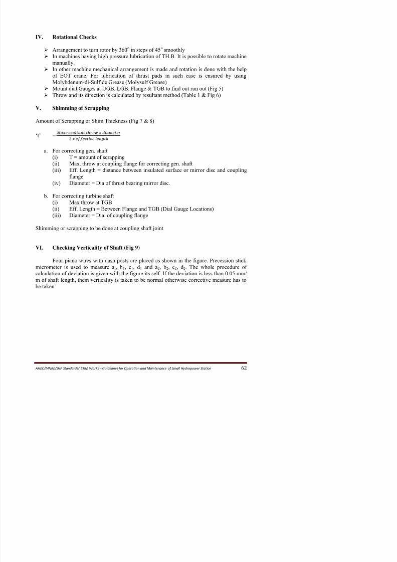
8/11/2019 Guidelines for Operation and Maintenance of Small Hydropower Station
http://slidepdf.com/reader/full/guidelines-for-operation-and-maintenance-of-small-hydropower-station 67/100
Arrangement to turn rotor by 360o in steps of 45o smoothly
In machines having high pressure lubrication of TH.B. It is possible to rotate machinemanually.
In other machine mechanical arrangement is made and rotation is done with the help
of EOT crane. For lubrication of thrust pads in such case is ensured by using
Molybdenum-di-Sulfide Grease (Molysulf Grease)
Mount dial Gauges at UGB, LGB, Flange & TGB to find out run out (Fig 5)
Throw and its direction is calculated by resultant method (Table 1 & Fig 6)
V. Shimming of Scrapping
Amount of Scrapping or Shim Thickness (Fig 7 & 8)
‘t’ =.
a. For correcting gen. shaft
(i)
T = amount of scrapping
(ii) Max. throw at coupling flange for correcting gen. shaft
(iii)
Eff. Length = distance between insulated surface or mirror disc and coupling
flange
(iv) Diameter = Dia of thrust bearing mirror disc.
b. For correcting turbine shaft
(i)
Max throw at TGB(ii) Eff. Length = Between Flange and TGB (Dial Gauge Locations)
(iii)
Diameter = Dia. of coupling flange
Shimming or scrapping to be done at coupling shaft joint
VI. Checking Verticality of Shaft (Fig 9)
Four piano wires with dash posts are placed as shown in the figure. Precession stick
micrometer is used to measure a1, b1, c1, d 1 and a2, b2, c2, d 2. The whole procedure of
calculation of deviation is given with the figure its self. If the deviation is less than 0.05 mm/
f h ft l th th ti lit i t k t b l th i ti h t
Table – 1

8/11/2019 Guidelines for Operation and Maintenance of Small Hydropower Station
http://slidepdf.com/reader/full/guidelines-for-operation-and-maintenance-of-small-hydropower-station 68/100
AHEC/MNRE/SHP
Standards/
E&M
Works
–
Guidelines
for
Operation
and
Maintenance
of
Small
Hydropower
Station
63
RESULTANT METHOD OF ALIGNMENT
(ACTUAL EXAMPLE OF UNIT-I OF A POWER STATION)(VECTORIAL RESULTANT – AT FIG. 6)
Position
of Dial
Gauge
Upstream Side Dial Gauge Down Stream Side Dial Gauge
No. of
Point
at
Shaft
UGB
a
LGB
c
Flange
e
TGB
g c-a
c-a g-a
UGB
b
LGB
d
Flange
f
TGB
h d-b f-b h-b
No. of
Point
at
Shaft
00 0 0 0 0 0 0 0 0 0 0 0 0 0 0 0 2
450 1 + ½
D i a
l G a u g e w a s n o t
f i x e d
– 32 – 46
D i a
l G a u g e w a s n o t – 31.5 – 45.5 0
D i a
l G a u g e w a s n o t
f i x e d
+ 1 + 1
D i a
l G a u g e w a s n o t
f i x e d
+ 1 + 1 3
900 2 0 – 40 – 85 – 40 – 85 + 3½ + 3 + 30 – ½ + 26½ 4
1350 3 0 – 40 – 86 – 40 – 86 + 6½ + 13 + 31 + 6½ + 24½ 5
1800 4 0 – 30 – 65 – 30 – 65 + 7 + 28 + 71 + 21 + 64 6
2250 5 + 1 – 8 – 22 – 9 – 23 + 7 + 41 + 80 + 34 + 73 7
2700 6 – ½ + 15 + 26 + 15½ + 26½ + 7 + 30 + 76 + 23 + 69 8
3150 7 0 + 6 + 17 + 6 + 17 + 3 + 18 + 51 + 15 + 48 13600 8 – 1 + 4 + 14 + 5 + 15 + 1 – 6 – 1 – 7 – 2 2
Note: (a) The readings of upstream side dial gauges are not acceptable as closing error is more.
(b) Unit-II side readings are fine because (i) closing error is negligible (ii) curve plotted along X-Y axis is nearer to sine curve (iii)
these are confirmed in subsequent rotation also. Further calculations and correction is based on these.
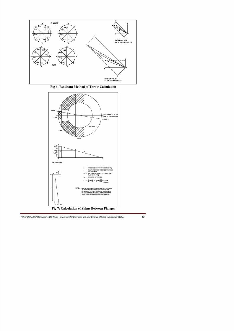
8/11/2019 Guidelines for Operation and Maintenance of Small Hydropower Station
http://slidepdf.com/reader/full/guidelines-for-operation-and-maintenance-of-small-hydropower-station 69/100
Fig 6: Resultant Method of Throw Calculation
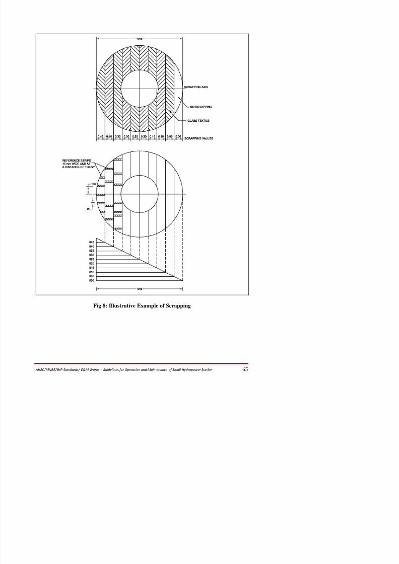
8/11/2019 Guidelines for Operation and Maintenance of Small Hydropower Station
http://slidepdf.com/reader/full/guidelines-for-operation-and-maintenance-of-small-hydropower-station 70/100
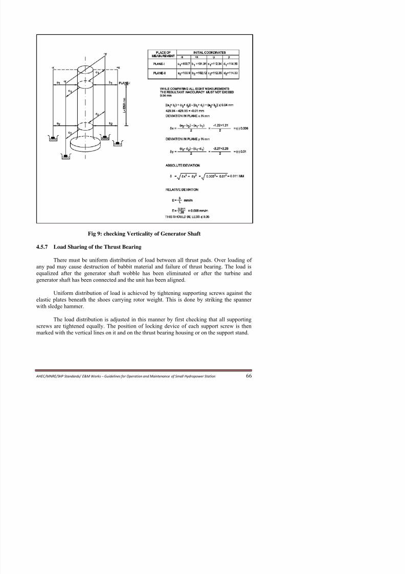
8/11/2019 Guidelines for Operation and Maintenance of Small Hydropower Station
http://slidepdf.com/reader/full/guidelines-for-operation-and-maintenance-of-small-hydropower-station 71/100
Fig 9: checking Verticality of Generator Shaft
4.5.7 Load Sharing of the Thrust Bearing
There must be uniform distribution of load between all thrust pads. Over loading ofany pad may cause destruction of babbit material and failure of thrust bearing. The load is
equalized after the generator shaft wobble has been eliminated or after the turbine and
generator shaft has been connected and the unit has been aligned.
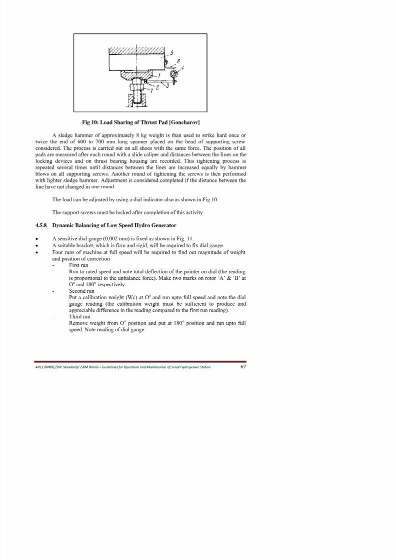
8/11/2019 Guidelines for Operation and Maintenance of Small Hydropower Station
http://slidepdf.com/reader/full/guidelines-for-operation-and-maintenance-of-small-hydropower-station 72/100
Fig 10: Load Sharing of Thrust Pad [Goncharov]
A sledge hammer of approximately 8 kg weight is than used to strike hard once or
twice the end of 600 to 700 mm long spanner placed on the head of supporting screw
considered. The process is carried out on all shoes with the same force. The position of all
pads are measured after each round with a slide caliper and distances between the lines on thelocking devices and on thrust bearing housing are recorded. This tightening process is
repeated several times until distances between the lines are increased equally by hammer
blows on all supporting screws. Another round of tightening the screws is then performed
with lighter sledge hammer. Adjustment is considered completed if the distance between the
line have not changed in one round.
The load can be adjusted by using a dial indicator also as shown in Fig 10.
The support screws must be locked after completion of this activity
4.5.8 Dynamic Balancing of Low Speed Hydro Generator
• A sensitive dial gauge (0.002 mm) is fixed as shown in Fig. 11.
• A suitable bracket, which is firm and rigid, will be required to fix dial gauge.
•
Four runs of machine at full speed will be required to find out magnitude of weightand position of correction
-
First run
Run to rated speed and note total deflection of the pointer on dial (the reading
is proportional to the unbalance force) Make two marks on rotor ‘A’ & ‘B’ at
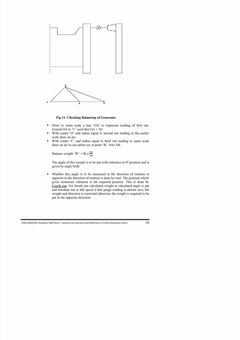
8/11/2019 Guidelines for Operation and Maintenance of Small Hydropower Station
http://slidepdf.com/reader/full/guidelines-for-operation-and-maintenance-of-small-hydropower-station 73/100
Fig 11: Checking Balancing of Generator
Draw to some scale a line ‘OA’ to represent reading of first run.
Extend OA to ‘C’ such that OA = AC
With centre ‘O’ and radius equal to second run reading to the earlier
scale draw an arc.
With centre ‘C’ and radius equal to third run reading to same scale
draw an arc to cut earlier arc at point ‘B’. Join AB.
Balance weight ‘W’ =
The angle of this weight is to be put with reference to 0o position and is
given by angle 0AB.
o
4.5.9 Alignment of Horizontal Generating Set
Adjustment of Turbine Shaft

8/11/2019 Guidelines for Operation and Maintenance of Small Hydropower Station
http://slidepdf.com/reader/full/guidelines-for-operation-and-maintenance-of-small-hydropower-station 74/100
Adjustment of Turbine Shaft
• The centre line of turbine bearing with respect to longitudinal axis of generator is
checked by stretching a horizontal wire through spiral casing and along bearing centre
line. Correct position of wire inside spiral casing is checked with inside micrometer.
• Bearing housings are centered with respect to longitudinal axis of generator by an end
gauge which is inserted into the bores of bearing shell
• Ensure clearenses of guide vanes at both ends are uniform and are between 0.2 to 0.6
mm. Feeler gauge is used to check these. These can be adjusted by tightening bolts.
When distributor is closed there should be no clearance in guide vanes.
• Measure clearance with feeler gauge between shaft and the lower bearing shell to
ensure correct position of rotating parts of turbine.
• If there is no clearance, it indicates that the shaft is resting on both bearings.
• The horizontal position of shaft is checked by placing a level successively on both
bearing journals. Then turn the level by 180o and place in the same position as before
and check level. Arithmetic mean of two measurements should be taken, if two
differ (more than one division). If difference is more investigate reasons and takeremedial measure,
• The permissible inclination in shaft is 0.04 to 0.06 mm per m length of shaft.
• The permissible inclination in transverse direction is 0.1 mm / m of shaft length. This
should also be checked with level.
• The radial clearance between runner and the cover plates which should not exceed 2.5
to 3.0 mm. these should be uniform.
•
The gaps in labyrinth seals should be with in 0.5 to 0.6 mm.• The axial gaps in labyrinth seals should also be measured and these should be within
0.2 to 0.3 mm. These are measured by pushing the rotating parts to extreme positions.
• All the clearances and gaps are measured again after turning the rotating parts through
180o and 360o. These should be with in permissible limit.
• 1 mm thick lead wire of 30 to 50 mm length is used to measure clearance between
turbine shaft and the upper bearing shell. Length of this wire are placed across the
shaft in two sections beneath the shell which is then tightened well. The thickness of
flattened wire thus indicate the clearance on top of the shaft which should be 0.2% ofshaft dia.
• The lateral clearance between the shaft and the lower shell are checked at a depth 10
to 12 mm below the plane in which bearing is split. These should be half of clearance
Procedure for preliminary alignment:

8/11/2019 Guidelines for Operation and Maintenance of Small Hydropower Station
http://slidepdf.com/reader/full/guidelines-for-operation-and-maintenance-of-small-hydropower-station 75/100
•
The turbine and generator shafts are forced to their outer most position after thegenerator is assembled and clearance between half coupling is ensured. This clearance
should be 5 to 6 mm (or as designed)
• A straight edge is pressed against the turbine or generator shaft along generator axis in
four diametrically opposite positions. Clearance if any is checked and equalized. For
this shims are provided beneath foundation fame.
• By measuring clearances between faces of half coupling at four points, alignment of
shafts at joint is checked.
•
The position of generator is first checked in vertical plane than in horizontal
• Misalignment is corrected by placing shims under foundation frame
• After this foundation bolts are tightened and locked
Fig 12: Misalignment of turbine and generator shafts [Goncharov]
Procedure for final alignment
• Check positions of half coupling
• Measure clearances between half couplings in the initial position and after turning
through 90o, 180o, 270o & 360o
• The position of half coupling should be same of initial position and after rotation by
360o
• For radial displacement of half couplings is measured by mounting a dial indicator on
a bracket fixed at turbine half coupling (Fig 13)
• Determine alignment and inclination of generator axis first in vertical, then in
horizontal plane. Record measurement in following table.

8/11/2019 Guidelines for Operation and Maintenance of Small Hydropower Station
http://slidepdf.com/reader/full/guidelines-for-operation-and-maintenance-of-small-hydropower-station 76/100
Site ofmeasurements
Clearance b between half-coupling ends,mm
Distances a to generatrices ofhalf-couplings, mm
Positions of rotating parts of generating set
00 900 1800 2700 3600 Mean
Clear-
ance
00 900 1800 2700 3600
Top a1;b1 + + + + + + + – – – +
Bottom a3;b3 + + + + + + – – + – –
Right a2;b2 + + + + + + – + – – –
Left a4;b4 + + + + + + – – – + –
Note: The “plus” sign indicates that measurements were carried out at this point.
• Compute displacements of generator rotor, for ensuring correct position
• Move generator rotor in correct position and check axis.
• Check position of stator
•
All measurements of clearances and displacement should be recorded viewing fromgenerator side.
• Magnitude ‘a’ are measured in one position and after turning rotating parts by 90 o,
180o, 270o & 360o
• End clearance ‘b’ is measured at four points in order to eliminate the effects of axial
displacement of the rotor. The mean clearance is then calculated for each position of
generator rotor (Fig 13)
•
The measurements are satisfactory if both [(a1 + a3)-(a2+a4)] and [(b1 + b3)-(b2+b4)]are with in 0.02 mm.
• All measurements are repeated till good set is achieved.
• Permissible deviations in alignment of horizontal hydro generating unit are given in
following table.
Rotational speed of
generating set, rpm
Permissible skewness and
eccentricity, mm
Up to 500 0.15
Up to 750 0.10
Up to 1500 0.08
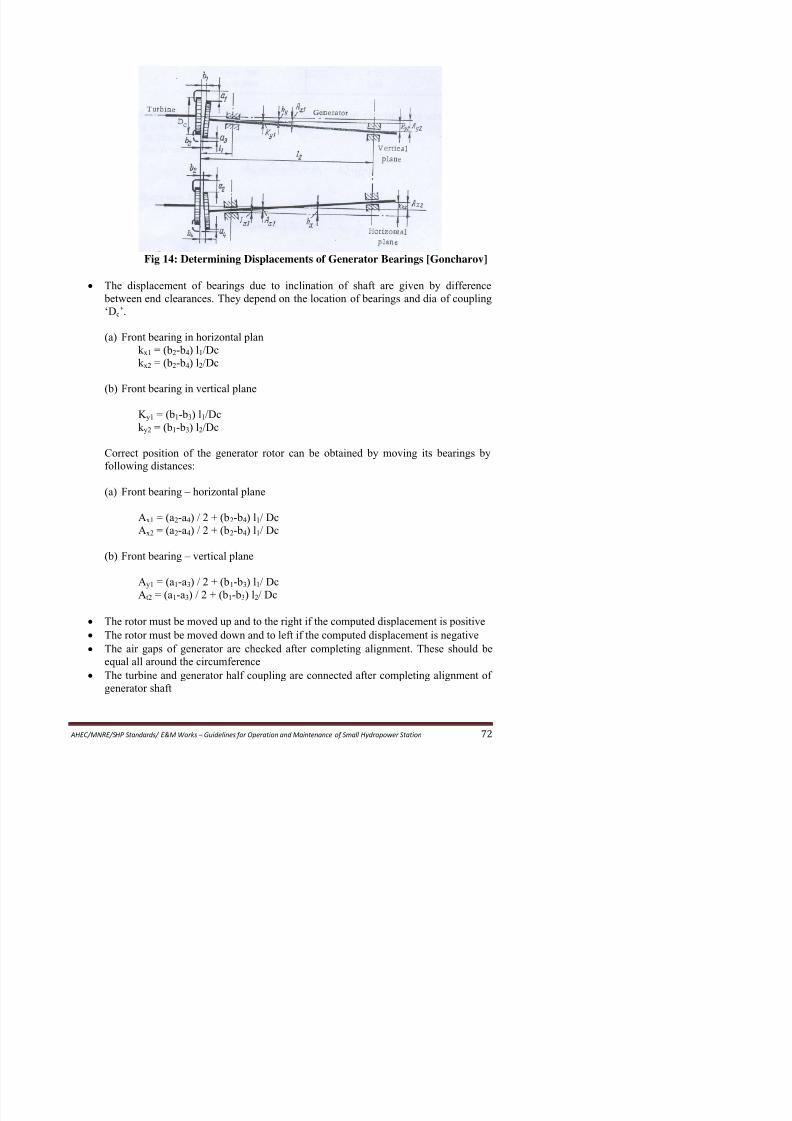
8/11/2019 Guidelines for Operation and Maintenance of Small Hydropower Station
http://slidepdf.com/reader/full/guidelines-for-operation-and-maintenance-of-small-hydropower-station 77/100
Fig 14: Determining Displacements of Generator Bearings [Goncharov]
• The displacement of bearings due to inclination of shaft are given by difference
between end clearances. They depend on the location of bearings and dia of coupling
‘Dc’.
(a) Front bearing in horizontal plan
k x1 = (b2-b4) l1/Dc
k x2 = (b2-b4) l2/Dc
(b) Front bearing in vertical plane
K y1 = (b1-b3) l1/Dc
k y2 = (b1-b3) l2/Dc
Correct position of the generator rotor can be obtained by moving its bearings by
following distances:
(a) Front bearing – horizontal plane
Ax1 = (a2-a4) / 2 + (b2-b4) l1/ Dc
Ax2 = (a2-a4) / 2 + (b2-b4) l1/ Dc
(b) Front bearing vertical plane

8/11/2019 Guidelines for Operation and Maintenance of Small Hydropower Station
http://slidepdf.com/reader/full/guidelines-for-operation-and-maintenance-of-small-hydropower-station 78/100
SECTION – III
GENERAL GUIDELINES
SECTION-III
GENERAL GUIDE LINES

8/11/2019 Guidelines for Operation and Maintenance of Small Hydropower Station
http://slidepdf.com/reader/full/guidelines-for-operation-and-maintenance-of-small-hydropower-station 79/100
GENERAL GUIDE LINES
1.0 GUIDELINES FOR TAKING OVER O&M OF SHP
The O&M of the plant shall be taken over from agency executing the project after due
diligence and checking on following conditions. A report shall be prepared and both handing
over and taking over party shall sign it. Following are the guide lines:
1.1 Operating condition of E&M equipment shall be monitored for 72 hrs continuous
running for full load condition and results, observations are noted. If any defect is
found, it shall be noted and corrected. This shall include turbine, generator,
auxiliaries, control metering and relay panels, HT and LT switchgear, main and
auxiliary transformer and switchyard equipments.
1.2 All civil building and structures such as water carrier system, lake diversion weir,
channel, pipe line, forebay, tailrace, draft tube, etc shall be monitored during load testand observations and defects noted. However all civil structures under water shall be
inspected on draining, if possible. Leakages, cracks on wall, and operation of main
gates shall be noted.
1.3 All the area of the plant shall be cleaned and all rooms checked for unwanted material
stored in it. Such material shall be taken out of building and stored in closed out door
yard.
1.4 All the spares of the E&M equipment shall be listed and their condition checked for
use during replacement. These shall include gate, valve, turbine, generator
transformers, breakers, panels, AVR and governor spares.
1.5 All the tools and instruments ordered for the plant shall be listed and their condition
checked.
1.6 Documents: Following documents shall be insisted upon:
• All plant and equipment drawings with as executed status.
• Type of plant such as ROR, dam based or canal based. The manpower for the ROR
plant is more because of the spread of hydraulic structures, the water channel and its
equipment.

8/11/2019 Guidelines for Operation and Maintenance of Small Hydropower Station
http://slidepdf.com/reader/full/guidelines-for-operation-and-maintenance-of-small-hydropower-station 80/100
•
The number of shifts/ hours the plant is going to work e.g. one shift or three shift. A plant with 3 shift working will need more staff than a single shift.
• Location of the plant, a remotely located plant will need additional staff for the
support services such as transport, maintenance of residences etc.
This may increase the strength of the remotely located ROR plant. However the
manpower can be kept minimum by employing a multidisciplinary force such as an
engineer with experience in civil and electromechanical work. Or technician with
driving experience etc. The guiding factor is safety of equipment and manpower.
Other method is to employ local labor, during requirement of additional work such as
rainy season where inspection of water channel is needed or during annual maintenance
work. It will benefit the plant, if these persons are given proper on job training.
2.2 SELECTION
Man power required for operation and maintenance shall be selected before
commercial operation of the plant.
• The operation staff shall be selected well in advance preferably during the pre-
commissioning and commissioning of the plant.
• The experience of the persons shall be in hydro generating plant, DG plant of a co-
generation plant. An experience on large electrical substation with DG set may be
accepted.
• Plant incharge having basic degree/ diploma in electrical with experience in civil and
mechanical works is most suitable.
• Testing engineer is most important for any generating plant. He should be
experienced engineer familiar with all equipment testing to take decision in case of
any fault on electrical equipment such as generator, transformer and switchgear. This
being a specialized job it may be difficult to get such persons and to hold them as
such can be engaged by group of plants or among the IPPS in the area.• For the technician an ITI certificate with hands on experience in electro-mechanical
work such as DG plant, electrical installation, hydraulic equipment, electrical panel,
PLC panels cabling work etc.
C t t l k h i il i t ldi d f b i ti t b
• On placing them on operation duty they shall be periodically assessed for their
performance in actual operation such as start of units etc.
8/11/2019 Guidelines for Operation and Maintenance of Small Hydropower Station
http://slidepdf.com/reader/full/guidelines-for-operation-and-maintenance-of-small-hydropower-station 81/100
3.0 ESSENTIAL T&P, INSTRUMENTS ETC
(i) Ordinary tools, instruments
For effective maintenance it is necessary to list out all required ordinary T&P as
also assess quantity and arrange the same otherwise it may become difficult even
for a skilled and capable technicians to carryout the require maintenance job.
Ordinary T&P includes different type & sizes of screw drivers, pliers, spanners
hammers etc.
(ii) Special T&P
Such type of T&P is required during assembly or dismantling of machines. For
example, rotor lifting device and endless slings, pole turning device, shaft lifting
device, rotating device and slings for alignment, shaft extension pieces and so on.
These are not required for day to day maintenance, as such these should be
properly stored and secured. Necessary maintenance, if required, must be carried
out on these devices in time. Slings should be stored duly coated with preservatives as recommended by the manufactures.
4.0 FIRE PROTECTION & FIRE FIGHTING
It is necessary to install necessary hydrant points fire extinguishers at different
locations of the power station as per recommendations of district fire officer.
Periodic drill of use of different types of fire extinguishers is must so that staff onduty in the power plant could operate these in case of emergencies.
First aid boxes as per recommendation of Factory Rules must be kept in the PS and
these should be inspected periodically by station incharge. Timely recoupment of consumed
items must be ensured by shift incharge.
Shift incharge should also ensure timely refilling of fire extinguishers installed in the
powerhouse. He must periodically check working of hydrant points.
Smoking inside power station should be prohibited. Throwing match sticks and other
burning stuff may some time create fire in the power station.
o Sand and water buckets
5.0 SAFETY ASPECT OF RUNNING SHP

8/11/2019 Guidelines for Operation and Maintenance of Small Hydropower Station
http://slidepdf.com/reader/full/guidelines-for-operation-and-maintenance-of-small-hydropower-station 82/100
It is said that 90% of accidents are avoidable. Out of these 20% are due to faulty
conditions and 20% due to faulty behavior and 60% due to both.
Accidents cause human suffering and loss of production to the organization. Safety
measures are therefore, essential. Success of safety measures depends on safety mindedness
of the management supervisions and workers. Some of the methods to improve safety
consciousness are given below:
• Prompt investigations pin pointing cause of accident and remedial measures
• Use of personal protective equipment such as helmet, goggles, gloves safety belts etc.
• Arousing safety consciousness through the use of posters, films, journal, safety talks,
safety competition etc.
General Safety Precautions in SHP
• All voltage level, even low shall be considered dangerous even though the voltage
may not be high to cause shock.
• All electrical circuit to be treated live and no work should be carried out with out
proper shut down and ensuring that it is
(i) De-energised (ii) Insolated from all sources
(iii) Effectively connected with ground
Fundamental on Safety
Prevention of accidents require whole hearted cooperation of all members of
organization. A capable, mentally alert employee will avoid accident.
Unsafe acts which may cause accidents are as follows:
-
Operation of an equipment with out authority or warning.- Operating without proper instructions
- Making safety device inactive
- Working nearby dangerous or live electrical equipment which could conveniently be
denergised

8/11/2019 Guidelines for Operation and Maintenance of Small Hydropower Station
http://slidepdf.com/reader/full/guidelines-for-operation-and-maintenance-of-small-hydropower-station 83/100
Safety Precautions and Practices in Operating and Maintenance
• No unsafe operation will ever be permitted. Feedback regarding unsafe operation/
condition should be taken into consideration with proper spirit and review should be
made to avoid accidents.
• Interlocks should not be by-passed unless it is very essential. Written permissions
should be obtained from the superintendent/ incharge of the station. Extra precaution
should be taken by all the parties during such cases.
•
Equipment are designed for certain operating conditions, it should be operated within prescribed operations limits. Overstressing of the equipment should be for minimum
possible time with minimum percentage of overloading. This will avoid damage to the
equipment.
• Operation and Maintenance staff should be familiar with the station layout and
operations limits of different equipment such as breakers, transformers, isolators CTs,
PTs, etc. A person should be allowed to operate or take over the equipment only after
he has acquired adequate knowledge of the equipment.• Operation should be carried out as per Operations Instructions. This will help in
carrying out operations safely and maintaining uniformity. In case of any
modifications/ change in the layout operating instructions should be reviewed.
• Booklets/ manufacturer’s instructions for different equipment should be available and
should be referred to before taking out equipment for maintenance.
• It is the responsibility of the supervisor to interpret correctly and explain safety rules
and regulations to all the persons concerned and ensure that they thoroughly
understand the same.
• Breach of safety rules should be suitably dealt with.
• Only authorized persons shall be allowed to carryout operation and maintenance.
• Supervisor shall guard against the use of defective safety appliances, tools, and
materials.
• In case of any emergency, in which quick action is necessary, in order to safe guard
personals or property, only authorized persons will take necessary action. Under no
circumstances attempt shall be made to carryout operations which are not safe.• All persons must use the standard protective equipment intended for the job.
• All protective equipment should be periodically tested.
• Metal ladders should not be used in switchyard.
• While working on the breaker, its operating mechanism should be de-energized such
as discharging spring, releasing air pressure etc.
• Transformer should be discharged and grounded from all sides (windings). Neutral

8/11/2019 Guidelines for Operation and Maintenance of Small Hydropower Station
http://slidepdf.com/reader/full/guidelines-for-operation-and-maintenance-of-small-hydropower-station 84/100
grounding of the transformer should not be treated as grounding.• Current transformer secondary should never to be left open circuited.
• After cutting out capacitor bank, it should be allowed to discharge through discharge
PT for about 10 minutes. The bank should be grounded with hot stick before
commencing the work.
• ASKAREL compound used in capacitor bank as a dielectric is very toxic and harmful.
Hence, should be handled with great care.
• Apparatus, frame work and other non-current carrying metal parts associated with
power system are to be effectively grounded.
• Lighting arresters shall be grounded independently.
• Isolating switches provided for Generators and synchronous condensers and other
rotating machines should never be opened when connected to any voltage source even
when the machine is carrying no load.
• The areas should be cordoned off indicating location of work on the particular
equipment.
•
Use of safety tags must be ensured while allowing shut down for maintenance onsome part/ equipment.
6.0 GUIDELINES FOR DOCUMENTATION
Documentation
Documentation at all levels of work done is necessity for any references and analysis
of data/information in future as and when required.
Roll of operation staff is very important in registering all valid information operating
parameters such as temperature, vibrations pressure, generation, voltage current etc. in the
operation log books and shift registers.
Every event should clearly mention frequency, voltage, MVAR, MW, MWH at the
instant with other necessary data e.g. alarms, annunciations temperatures, forebaylevels/reservoir levels, inflows etc. as may be necessary from case to case.
Any tripping event should be clearly noted with relevant details, such as relay
ti d t il di t b d d t l i t t R t ti ti iti
Results of test and measurements carried out during maintenance should be tabulated
in standard formats and this should include the commissioning and acceptable values are
applicable for proper comparison and planning remedial action.

8/11/2019 Guidelines for Operation and Maintenance of Small Hydropower Station
http://slidepdf.com/reader/full/guidelines-for-operation-and-maintenance-of-small-hydropower-station 85/100
The log books and log sheets normally maintained in SHPs are given in annexed
table:-
Operating Condition Record Sheets
Type Description of Log Purpose/used for Location/authority
1. Log Books Very important station record of events.
Helps during even analysis by others.a. Control Room Shift
Log Book
Record of events date and time wise and
sequential in case of operation carried out.
This will also record any instructions
given or taken from. Left side of the page
to record specific equipment operated and
right side events such as tripping, set
synchronizing, taking over shift with
signature switchyard operations etc.
Control Room Shift
Charge Engineer
b. Turbine Room Shift
Log Book
All turbine and its Aux. operation and
events, same as 1.a above.
Turbine operator
2. Log Sheets Gives station equipment load condition.
Helps in assessing during event analysis.
a. Control Room Meter
Reading
Hourly readings of all panel metes,
transformer auxiliaries, generator and
transformer temperature, and generalcondition of equipment. Ambient temp.
Control room / assistant
shift engineer / shift
engineer.
b. Control room energy
meter log sheet.
Hourly KWH meter, import – export
meter.
Aux. consumption meter.
Control room / shift
charge engineer.
c. Turbine room log
sheet
Hourly readings of bearing temperature,
aux. in service, pumps running, cooling
water pressure, compressor air pr, etc.
turbine water head/pressure and otherquantities as per manufacturer.
Turbine operator
3. Defect cum
Equipment Record
Equipment defects noticed by operation
and action taken by maintenance dept.
Corrections to be
recorded by maintenance
Type Description of Log Purpose/used for Location/authority
emergency outages, maximum equipment
temperatures during month, water utilized,

8/11/2019 Guidelines for Operation and Maintenance of Small Hydropower Station
http://slidepdf.com/reader/full/guidelines-for-operation-and-maintenance-of-small-hydropower-station 86/100
rainfall, lake contents etc., plant loadfactor, availability factor etc. the data is
important in studying plant performance
over years.
5. Daily report book
(duplicate)
For sending daily short summary to main
office of important events in plant. Shall
give rainfall, lake condition, water
utilized, water rate, generation, outages,
tripping of lines etc., and any otheroperation related information. DC battery
related voltage. Over loading of units etc.
Control room Resident
engineer/ manager
operation/ shift charge
engineer.
6. Station water
consumption
report. Monthly
(duplicate)
For mainly Hydro power plant, keeps
records of daily/ monthly water discharge
for generation, leakage, wind and
evaporation losses for storage dams,
meteorological and atmospheric data, atlake and at power house.
Control room. Resident
engineer/ manager
operations. Head works
engineer.
7. Station occurrence
record.
Record of all tripping, loss of time, and
cause of tripping, relay action etc.
Shift charge engineer,
manager operation.
8. Relay setting
register.
Record of all relay equipment relay setting
giving normal condition and during outage
of transformer or line, record of all
instructions for revision. This is an
extremely important register shall beavailable for reference at all times.
Manager operation/
Resident engineer
9. Station operation
manual
Manual giving all step by step operation
procedure for outages etc. Giving all
equipment data and equipment operating
parameter. Guidelines for emergency
operation, black start procedure, starting
and stopping of units, lake discharge and
other hydraulic data, all mechanical
installation operating procedure and
drawings, station interlocking drawings
Resident engineer,
manager operations.
10 Station safety Safety procedure for giving outages and Resident engineer
(NAME OF POWER STATION)
DAILY GENERATION/ TRANSMISSION REPORT FOR
GENERATION (MU) Monthly cum1 (MU) =_______. Yearly cum1 (MU)=__________

8/11/2019 Guidelines for Operation and Maintenance of Small Hydropower Station
http://slidepdf.com/reader/full/guidelines-for-operation-and-maintenance-of-small-hydropower-station 87/100
Unit
No.
Daily R/ Hours
Hr: Min
OUTAGES HOURS (Hr: Min) Available
Hr: Min
Deemed
Gen (MU)Planned Forced Misc.
Unit 1
Unit 2
Unit 3
…….
Total
TRANSMISSION (MU) Monthly Cum1 (MU)=_______ Yearly cum1 (MU)=_________
LINE-I LINE-II LINE-III
EXPORT
IMPORT
STATION DATA MW MVAR BUS/VOLT,
KV
FREQ,
Hz
AUX.CONSUMPTION
AVERAGELOAD MW
MAXIMUM
MINIMUM
TOTAL, INFLOW
Cumecs
WATER UTILIZED, Cumecs SPILLAGE, Cumecs
MAX RESERVOIR
LEVEL, M
MIN
RESERVOIR
LEVEL, M
MIN INTAKE
LEVEL, M
MAX TRW LEVEL, M SILT, (PPM
WEATHER
OUTAGE DETAILS COMMUNICATION STATUS: PLCC/P&T /
LDST/WIRELESS
OK/AS PER
REMAKRS
UNIT/
LINE
OUTAGE
TYPE
PO/FOR/MISC
TRIPPING/
OUTAGE TIME
Hr : Min
RESTORED
AT Hr: Min
TOTAL
OUTAGE
TIME
Hr: Min
Energy
Loss MU
(If Any)
REASONS
(NAME OF POWER STATION)
HOURLY STATION DATA REPORT FOR
Ti
BUS END
UNIT -1
GENERATION
UNIT -2
GENERATION
UNIT -3
GENERATION
…. TOTAL
GENERATION

8/11/2019 Guidelines for Operation and Maintenance of Small Hydropower Station
http://slidepdf.com/reader/full/guidelines-for-operation-and-maintenance-of-small-hydropower-station 88/100
Time
kV
GENERATION GENERATION GENERATION GENERATION
VOLTAGE
Hz
FREQ.
MW
MVAR MW MVAR MW MVAR MW MVAR MW
1:00
2:00
3:00
4:00
5:00
6:00
7:00
8:00
9:00
10:00
11:00
12:00
13:00
14:00
15:00
16:00
17:00
18:00
19:00
20:00
21:0022:00
23:00
24:00
OPERATION
PARAMETERS
NORMAL
VALUE
MAX TEMP., OC at Hrs. OC Hrs. OC Hrs. OC Hrs OC
STATOR WINDINGTHRUST BEARING
TURBINE GUIDE BEARING
UPPER GUIDE BEARING
(NAME OF POWER STATION)
DAILY TRIPPING REPORT FOR ______________ REPORT NO. (STATION)/TRIP/
Sl
N
Name of
Li / U i
Time
H Mi
Details of
i i
Replay operated along with
Al d Fl
Remarks

8/11/2019 Guidelines for Operation and Maintenance of Small Hydropower Station
http://slidepdf.com/reader/full/guidelines-for-operation-and-maintenance-of-small-hydropower-station 89/100
No Line/ Unit Hr : Min tripping Alarm and Flags
Power
Station end
Grid Station
end
COPY OF EVENT LOGGER/ DISTURBANCE RECORDER PRINTOUT ENCLOSED –
YES/NO
Specify reason if not attached_____________________
[Shift Incharge]
Name/ Designation
(NAME OF POWER STATION)
GENERATION REPORT
FOR THE MONTH OF _______________

8/11/2019 Guidelines for Operation and Maintenance of Small Hydropower Station
http://slidepdf.com/reader/full/guidelines-for-operation-and-maintenance-of-small-hydropower-station 90/100
DATE UNIT-1 UNIT-2 UNIT-3 ……… TOTAL DEEMED
MU MU MU MU GENERATION (MU)
1.
2.
3.
4.
5.
6.
7.
8.
9.
10.
11.
12. 13.
14.
15.
16.
17.
18.
19.
20.
21.
22.
23.
24.
25.
26.
27.
28.
29.
30.
(NAME OF POWER STATION)
M/C AVAILABILITY REPORT FOR THE MONTH OF
Unit GENERATION
(MU)
TOTAL
TIME
RUNNING
TIME
PLANNED
OUTAGE
FORCED
OUTAGE
MISCELLANEOUS OUTAGE DUE TO AVAILABILITY
IN HRS
%
AVAILABILITYHIGH LESS TRANSMISSION
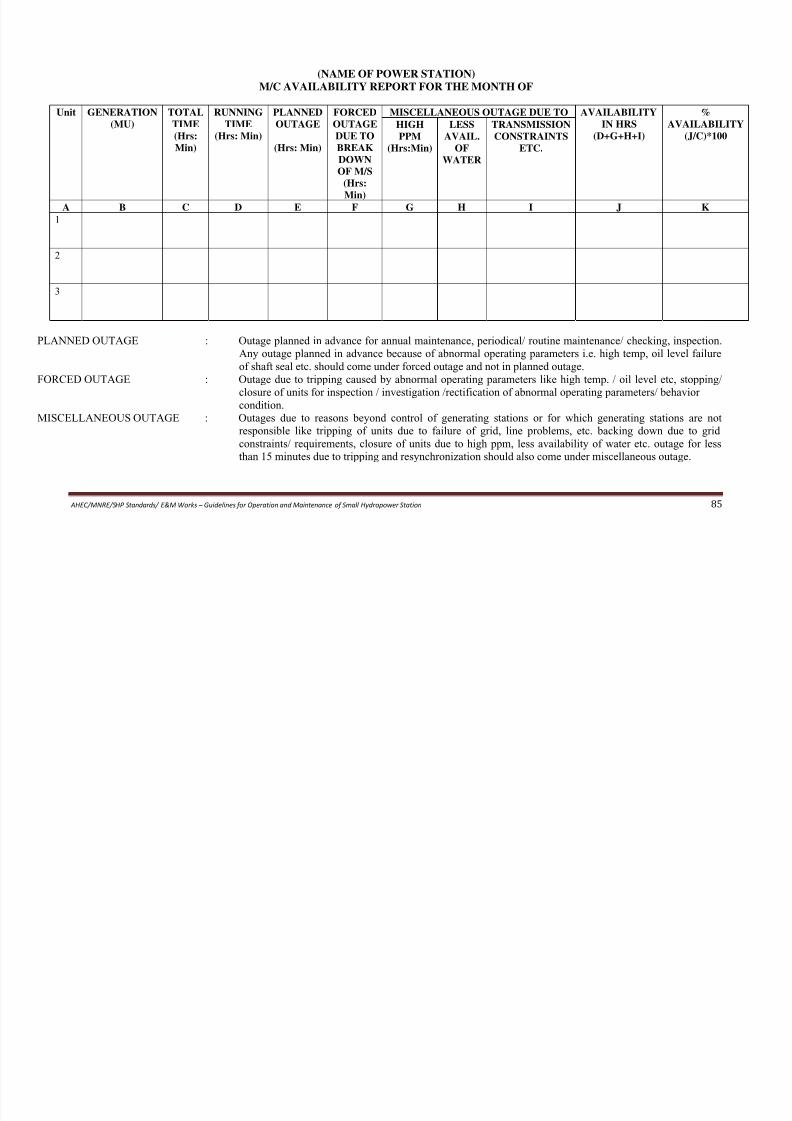
8/11/2019 Guidelines for Operation and Maintenance of Small Hydropower Station
http://slidepdf.com/reader/full/guidelines-for-operation-and-maintenance-of-small-hydropower-station 91/100
AHEC/MNRE/SHP Standards/ E&M Works – Guidelines for Operation and Maintenance of Small Hydropower Station
85
(MU) TIME
(Hrs:
Min)
TIME
(Hrs: Min)
OUTAGE
(Hrs: Min)
OUTAGE
DUE TO
BREAK
DOWN
OF M/S
(Hrs:
Min)
IN HRS
(D+G+H+I)
AVAILABILITY
(J/C)*100HIGH
PPM
(Hrs:Min)
LESS
AVAIL.
OF
WATER
TRANSMISSION
CONSTRAINTS
ETC.
A B C D E F G H I J K
1
2
3
PLANNED OUTAGE : Outage planned in advance for annual maintenance, periodical/ routine maintenance/ checking, inspection.
Any outage planned in advance because of abnormal operating parameters i.e. high temp, oil level failure
of shaft seal etc. should come under forced outage and not in planned outage.
FORCED OUTAGE : Outage due to tripping caused by abnormal operating parameters like high temp. / oil level etc, stopping/
closure of units for inspection / investigation /rectification of abnormal operating parameters/ behavior
condition.
MISCELLANEOUS OUTAGE : Outages due to reasons beyond control of generating stations or for which generating stations are not
responsible like tripping of units due to failure of grid, line problems, etc. backing down due to grid
constraints/ requirements, closure of units due to high ppm, less availability of water etc. outage for less
than 15 minutes due to tripping and resynchronization should also come under miscellaneous outage.
(NAME OF POWER STATION)
ABSTRACT OF OUTAGES FOR THE MONTH OF
UNIT NO.___________________

8/11/2019 Guidelines for Operation and Maintenance of Small Hydropower Station
http://slidepdf.com/reader/full/guidelines-for-operation-and-maintenance-of-small-hydropower-station 92/100
Sl
No
FORM TO TOTAL
TIME
Hr:Min
ENERGY
LOSS
(MU)
Reasons
DATE
dd/mm/yy
TIME
Hr:Min
DATE
dd/mm/yy
TIME
Hr:Min
PLANNED OUTAGE
FORCED OUTAGE
MISCELLANEOUS
OUTAGE
MONTHLY TRIPPING REPORT
FOR THE MONTH OF ____________________
Sl. Name of Type of Tripping Tripping Report Comments / Remarks

8/11/2019 Guidelines for Operation and Maintenance of Small Hydropower Station
http://slidepdf.com/reader/full/guidelines-for-operation-and-maintenance-of-small-hydropower-station 93/100
Sl.
No.
Name of
Units/ Line
Type of Tripping Tripping Report
No. & Date
Comments / Remarks
(if any)
INCHARGE [OPERATIONS]
NAME / DESIGNATION
(NAME OF POWER STATION)
DEEMED GENERATION REPORT FOR THE MONTH OF
Sl.
No
Unit
No.
DATE
dd/mm/yy
CONSTRAINTS/
BACKING DOWNCODE
TIME BACKING
DOWNPERIOD (t)
CAPACITY
BACKEDDOWN
ENERGY
LOSSELOSS (MU)
TOTAL
GENERATIONLOSSDURING
SPILLAGE
ENERGYDURING
DEEMED
GENERATIONGDEEMED (MU)FROMHr:MIN TOHr:Min

8/11/2019 Guidelines for Operation and Maintenance of Small Hydropower Station
http://slidepdf.com/reader/full/guidelines-for-operation-and-maintenance-of-small-hydropower-station 94/100
AHEC/MNRE/SHP Standards/ E&M Works – Guidelines for Operation and Maintenance of Small Hydropower Station
88
CODE PERIOD (t)
Hr
DOWN
B, IN MW
ELOSS (MU) LOSSDURING
THE DAY
GLOSS (MU)
DURING
THE DAY
GSPILLAGE
(MU)
GDEEMED (MU)Hr:MIN Hr:Min
NAME/ DESIGNATION

8/11/2019 Guidelines for Operation and Maintenance of Small Hydropower Station
http://slidepdf.com/reader/full/guidelines-for-operation-and-maintenance-of-small-hydropower-station 95/100
AHEC/MNRE/SHP Standards/ E&M Works – Guidelines for Operation and Maintenance of Small Hydropower Station
89
STATISTICAL ANALYSIS TRIPPINGS
POWER
STATION
LEGEND CLARIFICATION FROM THE
STTION
A B C D E F G H I J K L M N O P Q R S T U V W

8/11/2019 Guidelines for Operation and Maintenance of Small Hydropower Station
http://slidepdf.com/reader/full/guidelines-for-operation-and-maintenance-of-small-hydropower-station 96/100
AHEC/MNRE/SHP Standards/ E&M Works – Guidelines for Operation and Maintenance of Small Hydropower Station
90
LEGEND DESCRIPTION OF PROTECTION NO. OF OCCURRENCE
a.
b.
c.
d.
e.
f.
g.
h.
i.
j.
k.
l.
m.
n.
o.
p.
q.
r.
s.
t.
u.
v.
w.
Approved:
Issued:
(POWER STATION)
ANNUAL MAINTENANCE SCHEDULE
(FOR THE YEAR )
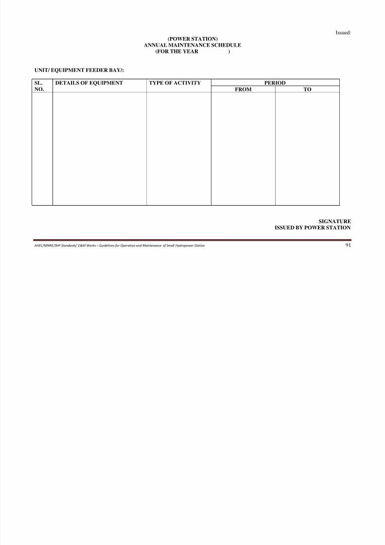
8/11/2019 Guidelines for Operation and Maintenance of Small Hydropower Station
http://slidepdf.com/reader/full/guidelines-for-operation-and-maintenance-of-small-hydropower-station 97/100
AHEC/MNRE/SHP Standards/ E&M Works – Guidelines for Operation and Maintenance of Small Hydropower Station
91
UNIT/ EQUIPMENT FEEDER BAY/:
SL.
NO.
DETAILS OF EQUIPMENT TYPE OF ACTIVITY PERIOD
FROM TO
SIGNATURE
ISSUED BY POWER STATION
(POWER STATION)
MONTHLY MAINTENANCE REPORT
(FOR THE MONTH)
UNIT/EQUIPMENT/FEEDER BAY/:
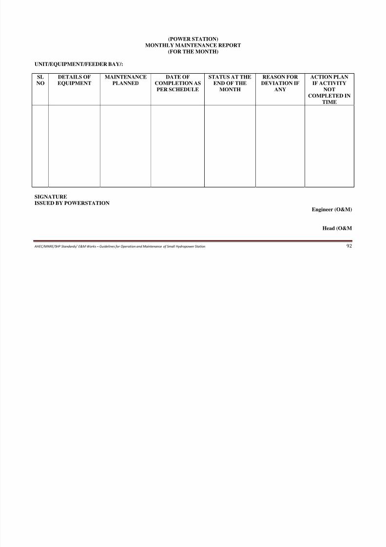
8/11/2019 Guidelines for Operation and Maintenance of Small Hydropower Station
http://slidepdf.com/reader/full/guidelines-for-operation-and-maintenance-of-small-hydropower-station 98/100
AHEC/MNRE/SHP Standards/ E&M Works – Guidelines for Operation and Maintenance of Small Hydropower Station
92
UNIT/EQUIPMENT/FEEDER BAY/:
SL
NO
DETAILS OF
EQUIPMENT
MAINTENANCE
PLANNED
DATE OF
COMPLETION AS
PER SCHEDULE
STATUS AT THE
END OF THE
MONTH
REASON FOR
DEVIATION IF
ANY
ACTION PLAN
IF ACTIVITY
NOT
COMPLETED IN
TIME
SIGNATURE
ISSUED BY POWERSTATIONEngineer (O&M)
Head (O&M
(POWER STATION)
BREAK DOWN STATUS
UNIT/ EQUIPMENT/ FEEDER BAY/:
DATE & TIME OF BREAKDOWN
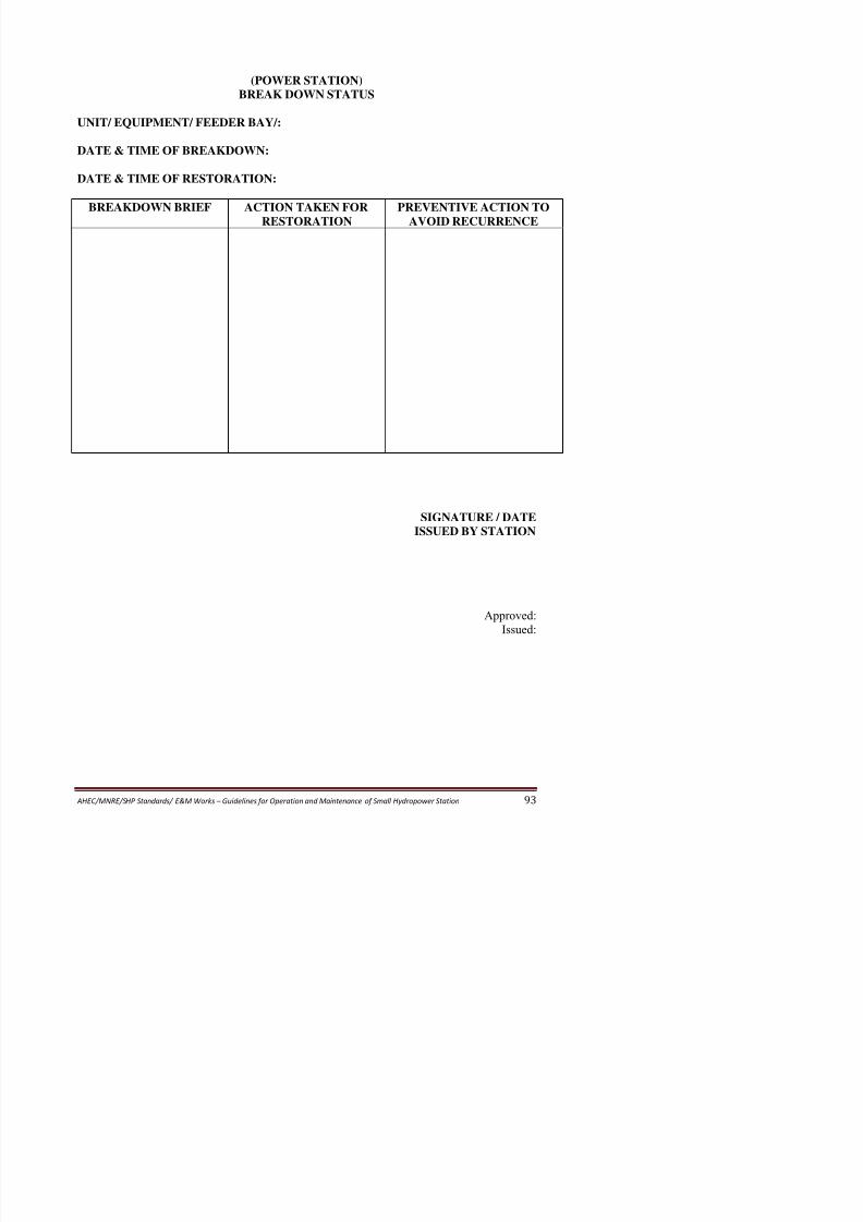
8/11/2019 Guidelines for Operation and Maintenance of Small Hydropower Station
http://slidepdf.com/reader/full/guidelines-for-operation-and-maintenance-of-small-hydropower-station 99/100
DATE & TIME OF BREAKDOWN:
DATE & TIME OF RESTORATION:
BREAKDOWN BRIEF ACTION TAKEN FOR
RESTORATION
PREVENTIVE ACTION TO
AVOID RECURRENCE
SIGNATURE / DATE
ISSUED BY STATION
(NAME OF POWER STATION)
OUTAGE REPORT
SL
NO
NAME OF
EQUIPMETN
STARTING RESTORATION TOTAL
OUTAGES
REASONS GENERATION
LOSS IN MU
ACTION
TAKEN FOR
PREVENTIVE
ACTION TODATE TIME DATE TIME

8/11/2019 Guidelines for Operation and Maintenance of Small Hydropower Station
http://slidepdf.com/reader/full/guidelines-for-operation-and-maintenance-of-small-hydropower-station 100/100
AHEC/MNRE/SHP Standards/ E&M Works – Guidelines for Operation and Maintenance of Small Hydropower Station
94
NO EQUIPMETN
OF THE
UNIT/
FEEDER
OUTAGES
TIME
(Hrs:Min)
LOSS IN MU TAKEN FOR
RESTORATION
ACTION TO
AVOID
RECURRENCE
DATE TIME
(Hrs:Min)
DATE TIME
(Hrs:Min)
ACTION TAKEN BY STATION:
[SHIFT INCHARGE]
NAME/ DESIGNATION