guidelines for the selection, design and construction of drilled shaft
TRANSCRIPT
I R-89-01
GUIDELINES FOR THE SELECTION, DESIGN AND CONSTRUCTION OF DRILLED SHAFT
FOUNDATIONS FOR BRIDGES IN ALABAMA
by
Dan A. Brown Kenneth W. Weinel
March 1990

Guidelines for the Selection, Design and Construction
of Drilled Shaft Foundations for
Bridges in Alabama
Dan A. Brown Assistant Professor
Kenneth w. Weinel Graduate Research Assistant
Department of Civil Engineering Harbert Engineering Center Auburn University Auburn, AL 36849-5337
TABLE OF CONTENTS
SUMMARY
LIST OF FIGURES AND TABLES . . . . . . . . . . . . . . . . . . . . . . . . . . . . . . . . . . .iii ACKNOWLEDGEMENTS
INTRODUCTION
ADVANTAGES AND DISADVANTAGES Advantages Disadvantages
GEOLOGY OF ALABAMA Coastal Plain Piedmont Paleozoic
DESIGN AND CONSTRUCTION Design . ....................... .
Design for Axial Loading Design for Lateral Loading
Construction ....•..............• Dry Open-Hole Construction Method ..•..•...•.. Casing Construction Method........ . •.••• Wet Construction Method.............. . ..••. Permanent casing Construction Method •.........••••. Example: Typical construction in Alabama .•....••..
SPECIFICATIONS AND BID DOCUMENTS
COST . . . . . . . . . . . . ~ . . . . . . . . . . . COMPARISON Cost Procedure Cost Procedure
for Driven Piles for Drilled Shafts ..
CONCLUSIONS ................................................. REFERENCES . . . . . . . . . . . . . . . . . . . . . . . . . . . . . . . . . . . . . . . . . . . . . . . . . . APPENDICES ..... .
Appendix A. Appendix B. Appendix c. Appendix D.
......................................... Design Procedure and Sample Calculation Suggested Specifications Bid Documents Cost comparison [I-565-5(22)]
ii
. . .
iv
1
2 2 3
5 -5 6 7
10 10 10 12 13 13 14 18 19 20
22
25 26 27
29
30
31
SUMMARY
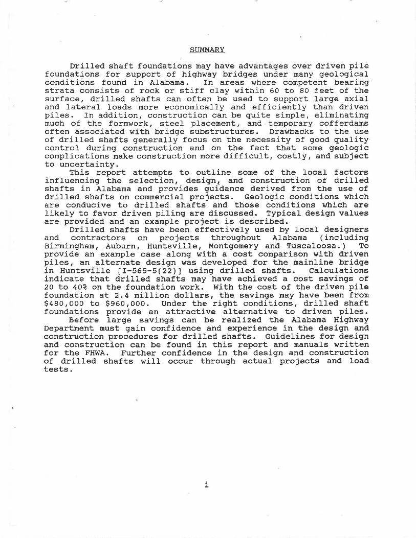
Drilled shaft foundations may have advantages over driven pile foundations for support of highway bridges under many geological conditions found in Alabama. In areas where competent bearing strata consists of rock or stiff clay within 60 to 80 feet of the surface, drilled shafts can often be used to support large axial and lateral loads more economically and efficiently than driven piles. In addition, construction can be quite simple, eliminating much of the formwork, steel placement, and temporary cofferdams often associated with bridge substructures. Drawbacks to the use of drilled shafts generally focus on the necessity of good quality control during construction and on the fact that some geologic complications make construction more difficult, costly, and subject to uncertainty.
This report attempts to outline some of the local factors influencing the selection, design, and construction of drilled shafts in Alabama and provides gufdance derived from the use of drilled shafts on commercial projects. Geologic conditions which are conducive to drilled shafts and those conditions which are likely to favor driven piling are discussed. Typical design values are provided and an example project is described.
Drilled shafts have been effectively used by local designers and contractors on projects throughout Alabama (including Birmingham, Auburn, Huntsville, Montgomery and Tuscaloosa.) To provide an example case along with a cost comparison with driven piles, an alternate design was developed for the mainline bridge in Huntsville ( I-565-5 ( 22)) using drilled shafts. Calculations indicate that drilled shafts may have achieved a cost savings of 20 to 40% on the foundation work. With the cost of the driven pile foundation at 2.4 million dollars, the savings may have been from $480,000 to $960,000. Under the right conditions, drilled shaft foundations provide an attractive alternative to driven piles.
Before large savings can be realized the Alabama Highway Department must gain confidence and experience in the design and construction procedures for drilled shafts. Guidelines for design and construction can be found in this report and manuals written for the FHWA. Further confidence in the design and construction of drilled shafts will occur through actual projects and load tests.
i

.:r·
LIST OF FIGURES AND TABLES
Figure
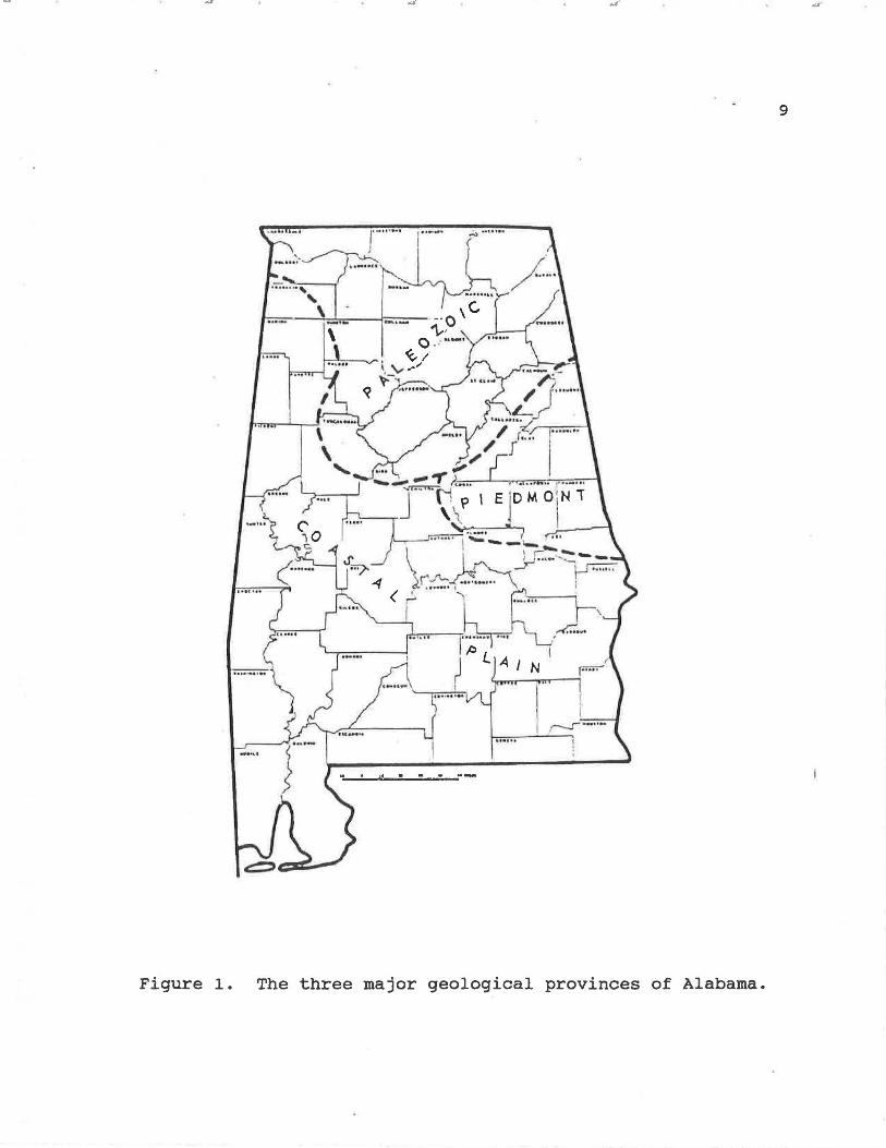
l. Three major geological provinces of Alabama 9
2. Typical drilled shaft with a bell or underream ...... 15
3. Probe holes and or rock anchors ............•....... 17
Table
1. Typical design values for end bearing and side friction ••.•.•. 12
2. Excavation costs for earth and rock .•••.••. . ...•.•. 27
iii
ACKNOWLEDGEMENTS
The information reported in this paper resulted from
interviews with a number of contractors and geotechnical engineers
who shared their experiences in the varied geology of Alabama. The
authors express their gratitude to Mr. Paul Wilson, Mr. Hal McKewen
and Mr. Danny Jennings of Russo Corp. , Mr. Bruce Long of Long
Foundation Drilling Co., Mr. Ed Munn of McKinney Drilling Co., Mr.
Luther Boudra and Mr. Bruce Bodner of Law Engi'neering, Inc., Mr.
Uday Bhate of Bhate Engineering Corp., and Mr. Rick Bourquard and
Mr. James Pegues of Ground Epgineering and Testing Service, Inc.
Financial support of the Alabama Highway Research Center made this
report possible and is gratefully acknowledged.
iv

INTRODUCTION
The Alabama Highway Department (AHD) has traditionally used
driven piles where deep foundations are indicated. However,
drilled shaft foundations may soon be considered as an alternate
to driven piles on future bridge construction projects. This
report has been prepared as an aide in the selection, design and
construction of drilled shaft foundations, by addressing the
following issues:
1
1. The advantages and disadvantages of using drilled shafts
for bridge foundations.
2. The geology of Alabama related to the use of drilled
shafts, and areas in which drilled shafts may or may not
offer advantages over driven piling.
3. The design and construction procedures for the
production of drilled shaft foundations in Alabama.
4. The relative cost of drilled shafts compared to driven
piles.
The information contained in this report has resulted from
interviews with state highway departments, geotechnical
engineering firms, and drilled shaft contractors. Further
information was obtained from literature published by the Federal
Highway Administration (FHWA) and the International Association
of Foundation Drilling (ADSC).

ADVANTAGES AND DISADVANTAGES
The following is a brief discussion of the advantages and
disadvantages of using drilled shaft foundations in Alabama.
2
Many of these .topics will be examined in more detail subsequently
in this report.
Advantages
1. Construction equipment is normally mobile, and
construction can proceed rapidly.
2. The excavated material and the drilled shaft .can easily
be inspected in most of the geological conditions found
in Alabama. Also, a probe hole can normally be drilled
to verify the integrity of the bearing stratum.
3. Changes in the geometry of the drilled shaft can be made
during the progress of a job if the subsurface
conditions so dictate. These changes may include
adjustment in diameter and penetration of the shaft.
4. Experienced contractors, equipment and materials for
construction of drilled shafts are readily available in
Alabama.
5. Drilled shaft foundations are applicable to a wide range
of soil and rock conditions. With proper drilling
equipment and blasting techniques, any formation
found in Alabama can be penetrated.
6. Large axial and lateral loads can be carried by a single
drilled shaft, thus eliminating the need for a cap.

AS" ,a·
7. Extremely large loads can be supported with drilled
shafts bearing on or within rock. Load transfer occurs
in both end bearing and side friction by socketing into
bedrock.
3
B. The use of a single drilled shaft in lieu of a group of
piles or a spread footing offers advantages with respect
to resistance to scour.
9. Load tests can be run with special instrumentation,
high-capacity loading systems, and a willingness of
local contractors to assist. Detailed information on
load transfer and capacities can be developed for the
State's geology.
10. Non-destructive testing techniques are available for
purposes of quality control in the production of drilled
shaft foundations.
Disadvantages
1. Construction procedures are critical to the .quality
of the drilled shaft, and careful inspection will be
requ~red by the AHD.
2. General experience with design and construction of
drilled shafts is lacking in the AHD; however, this
limitation can be overcome with assistance from the
Auburn University Civil Engineering faculty andjor local
consultants. A pilot program using drilled shafts would
also be very instructive.
,.;~·
3. Using a single drilled shaft eliminates the redundancy
present in a large group of driven piles.
4. Construction difficulties may be present in some types
of geology (such as severely eroded limestones and
coastal sands); cost advantages may not be realized
under such conditions.
5. Lack of a clear definition of soil and rock excavation
can result in construction disputes over pay items in
some types of geology (generally Piedmont areas).
4
.. ·
GEOLOGY OF ALABAMA
The design and construction of drilled shafts is greatly
influenced by the geology found at the construction site. The
geology of Alabama varies from the coast to the mountains with
three major geological provinces which include the following:
Coastal Plain, Piedmont, and Paleozoic which includes the Valley
and Ridge, Interior Low Plateaus, and Appalachian Plateaus. The
locations of the three major provinces are shown on Figure 1.
Coastal Plain
The Coastal Plain is the largest of the three provinces and
is composed mainly of gravel, sand, silt, and clay which were
deposited before the ocean receded to its present level. In the
central portion of Alabama these soils are often underlain by
chalk, marl or other hard clay formation, while in southern
Alabama sand and gravel are found to great depths.
In much of central Alabama geological conditions are ideal
for drilled shaft construction. The clay and underlying
formations can be augered and i1nspected with little difficulty.
By "socketing" shafts into the chalk or marl, large loads can be
transferred by side friction and end bearing. Little research
has been conducted to calculate actual load carrying values, but
allowable end bearing pressures can be expected to be the range
of 10 to 30 kips per square foot (ksf). Further details of
design and construction are described later in this report.
5

6
The geological conditions found along the coast of Alabama
present more design and construction problems due to the
noncohesive soils and the high water table. Such conditions
often necessitate the use of slurry during construction; this
technique can be effective, but increases costs significantly.
The Florida DOT has had success with drilled shafts under similar
geological conditions, and experienced contractors exist to do
such w~rk. However, details of design and construction using
slurry techniques will be considered beyond the scope of this
report.
Piedmont
The Piedmont is found in the east central portion of the
state and is underlain by very old metamorphic rocks,
predominantly gneiss and schist, but also greenstone, phyllite,
quartzite, metaconglomerate, marble, metachert, dolomite,
metasandstone, metasiltstone, slate, quartz and granite. These
rocks have been subjected to millions of years of physical and
chemical forces that have transformed the original rocks into
various states of decomposition from relatively loose residual
soils near the surface to hard, massive rocks at depth.
The Piedmont provides excellent conditions for drilled shaft
construction with cohesive soils, hard bearing material and
usually a low water table. The hard rocks such as schist and
gneiss are difficult to penetrate and design is based
predominantly on end bearing with a value up to 100 ksf. Safe
inspection is also possible with the use of temporary casings.
The major construction problem is encountering boulders prior to
reaching sound rock.
Drilled shafts have been used successfully in the Piedmont
on many structures in Auburn including the stadium addition,
Harbert Engineering Center, Library expansion, new parking deck,
and presently the Aerospace building. Further discussion on the
design and construction of drilled shafts in the Piedmont is
described later in this report.
Paleozoic
7
The Paleozoic is found in northern Alabama and contains the
following provinces: Valley and Ridge, Interior Low Plateaus,
and Appalachian Plateaus. The Paleozoic consists of very old,
weathered sedimentary rocks including limestone, dolomite, chert,
shale, sandstone, claystone, coal and conglomerate.
The bedrock is generally overlain by clayey soils which may
contain boulders. Although most of the Paleozoic limestones are
relatively sound, karstic activity is present in some of the
limestone and dolomite rock formations. In particular, the
Conasauga Limestone and Ketona Dolomite in certain parts of
Birmingham are noted as containing significant irregularity in
the rock surface. Other construction problems can result due to
pinnacles found in limestone formations and old mines in coal
bearing formations. References to Brown {3) and the FHWA (5)
provide more information on design and construction under these
conditions. The bedrock of the Paleozoic generally has a high
bearing capacity. Allowable bearing pressures in hard, sound

:...
. .
..... • '
8
limestones are typically in the range of 80 to 100 ksf; due to
the difficulty in drilling, side friction is not usually
considered for design purposes. Design in the more easily
drilled rocks such as shale and sandstone may include rock
sockets designed for both end bearing and side friction. Typical
values for allowable end bearing range from 20 to 60 ksf, and
typical values for side friction range up to 14 ksf. With a
temporary casing in place the integrity of the bearing material
can be inspected, and probing of the bearing stratum may be used
to check for cavities, seams, mines and etc .
Many drilled shaft projects have been constructed in the
Paleozoic province from Tuscaloosa to Huntsville. Drilled shafts
appear to be the type of deep foundation used on most major urban
and industrial projects in these areas. Even in the difficult
pinnacle and karstic limestone found in parts of Birmingham,
drilled shafts have been used with success by local designers and
contractors. The good results are due to experience and special
design and contractual provisions to deal with the highly
irregular limestone. Separate pay items are generally used for
mobilization, soil excavation, rock excavation, and concrete
volume. More discussion on pay items, design and construction
follows in this report.
9
Figure 1. The three major geological provinces of Alabama.

10
PESIGN AND CONSTRUCTION
Load transfer of drilled shafts may occur through end
bearing and/or side friction. The method of construction
influences the assurance of design values through inspection of
the bearing stratum and shaft walls. The designer must
understand construction methods to efficiently utilize drilled
shafts, with the selection of appropriate design values and
assumptions. An excellent design manual is available through the
FHWA for general information on design and construction of
drilled shafts; the information provided in this report is
intended to emphasize the unique features of local (Alabama)
practice rather than repeat information which is available in the
FHWA manual Drilled Shafts: Construction Procedures ~ Design
Methods. The emphasis of this section of the report will be on
construction methods most common to Alabama, and a brief summary
on design. Construction methods influence the design of drilled
shaft foundations and vice versa.
DESIGN
Drilled shafts for highway bridges are typically used as a
single shaft for a single column, and generally must be designed
for both axial and lateral loading.
Design !Qr Axial Loading
The drilled shaft foundation must be designed to carry the
ultimate load and meet specified settlement criteria for working
loads. The following is a summary of the design procedure for
11
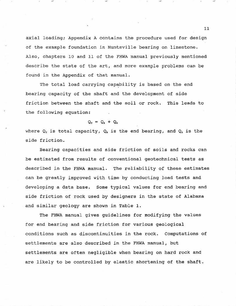
axial loading; Appendix A contains the procedure used for design
of the example foundation in Huntsville bearing on limestone.
Also, chapters 10 and 11 of the FHWA manual previously mentioned
describe the state of the art, and more example problems can be
found in the Appendix of that manual.
The total load carrying cap~bility is based on the end
bearing capacity of the shaft and the development of side
friction between the shaft and the soil or rock. This leads to
the following equation:
QT = Oa + Os
where QT is total capacity, Q8 is the end bearing, and Q5 is the
side friction.
Bearing capacities and side friction of soils and rocks can
be estimated from results of conventional geotechnical tests as
described in the FHWA manual. The reliability of these estimates
can be greatly improved with time by conducting load tests and
developing a data base. Some typical values for end bearing and
side friction of rock used by designers in the state of Alabama
and similar geology are shown in Table 1.
The FHWA manual gives guidelines for modifying the values
for end bearing and side friction for various geological
conditions such as discontinuities in the rock. Computations of
settlements are also described in the FHWA manual, but
settlements are often negligible when bearing on hard rock and
are likely to be controlled by elastic shortening of the shaft.
,w<"
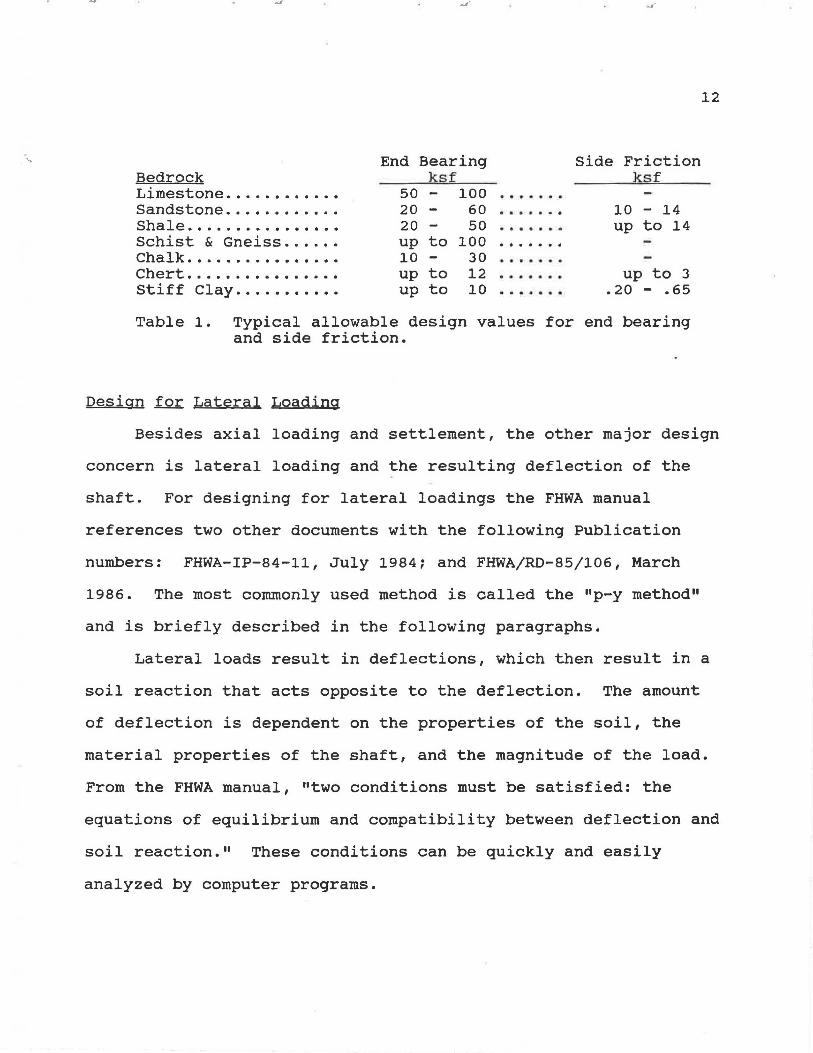
·. ~ End Bearing Side Friction Bedrock ksf ksf Limestone .....•...... 50 - 100 ....... Sandstone ............ 20 - 60 ....... 10 - 14 Shale ................ 20 - 50 ....... up to 14 Schist & Gneiss ...... up to 100 . . . . . . . Chalk . ............... 10 - 30 ....... Chert . ............... up to 12 . . . . . . . up to 3 Stiff Clay . .......... up to 10 • • • a • • • .20 - .65
Table 1. Typical allowable design values for end bearing and side friction.
Design for Lateral Loading
12
Besides axial loading and settlement, the other major design
concern is lateral loading and the resulting deflection of the
shaft. For designing for lateral loadings the FHWA manual
references two other documents with the following Publication
numbers: FHWA-IP-84-11, July 1984; and FHWA/RD-85/106, March
1986. The most commonly used method is called the 11 p-y method"
and is briefly described in the following paragraphs.
Lateral loads result in deflections, which then result in a
soil reaction that acts opposite to the deflection. The amount
of deflection is dependent on the properties of the soil, the
material properties of the shaft, and the magnitude of the load.
From the FHWA manual, "two conditions must be satisfied: the
equations of equilibrium and compatibility between deflection and
soil reaction." These conditions can be quickly and easily
analyzed by computer programs.
The program COM624, (commercially available in a personal
computer version known as LPILEl), uses the "p-y method" to
calculate deflections over the entire length of the drilled
shaft. Factors which are used by LPILEl include: the loading;
the geometry, stiffness, and penetration of the drilled shaft;
the soil properties; and the interaction between the drilled
shaft and the superstructure. A companion code, PMEIX, can be
used to determine the properties of the shaft for input into
COM624. The results of COM624 can be checked against design
tolerances and the shaft can be modified as needed.
It is noted that the drilled shaft is designed for both
axial loading and lateral loading conditions either may control
the size and embedment length of shaft. Where large lateral
loads are present (as in water crossings), it may often be the
case that lateral loads govern design.
CONSTRUCTION
13
There are four major types of construction including the dry
open-hole method, casing method, permanent casing method and wet
(or slurry) method. The construction of a single drilled shaft
in Alabama is most often done using the casing method, but
conditions may require the use of other construction methods in
conjunction andjor with other construction modifications for
completion and performance as designed.
~ Open-hole Construction Method
The dry open-hole construction method is the simplest of the
four construction methods. The procedure consists of drilling
.:~·
the shaft excavation to the bearing depth, removing accumulated
··. . water and loose material, inspecting the shaft and then placing
the shaft concrete and steel in a relatively dry excavation.
14
The dry construction method should only be attempted in
cohesive soils which remain stable without detrimental caving,
sloughing or swelling over a four hour period; clays in central
Alabama exhibit these properties. Inspection of the shaft can
only be made from the top of the excavation, unless a casing is
inserted to allow an inspector to enter the excavation and
observe the bearing stratum. If both the sides and base can be
inspected, the designer has added assurance in designing for side
resistance and end bearing. After inspection is complete, the
reinforcing cage and concrete is placed as shown on the plans.
Where conditions warrant, economies are often achieved by
constructing a "bell bottom" or "underream" to enlarge the base
of the shaft and increase available end bearing. Stiff,
unfissured clays and the marl or chalk formations are conducive
to bell bottom footing construction, as shown in Figure 2.
Casing Construction Method
The casing construction method is used at sites where
sidewall seepage is expected and the dry open-hole construction
method is not appropriate. In this method, the hole is advanced
by the same manner as the dry construction method and a casing is
placed in the excavation before detrimental caving, sloughing or
swelling occurs.
permeable strata.
The casing also seals off seepage from upper
The drilling continues through the casing in a

z~ <LJ uo :r~ 1->D..c::: LJ< 0>
BELL ANGLE TYPICALLY 45°- srf
PAD OR TOE
AXIAL LOAD
~ SHAF"T DIAMETER CAN VARY WIDELY
REINFORCING STEEL (FREQUENTLY REQUIRED BY DESIGN)
SIDE RESISTANCE {SIDE FRICTION)
BASE RESISTANCE {END BEARING)
Figure 2. A typical drilled shaft with a bell or underream.
15

16
telescoping manner until reaching the proper bearing stratum.
The final diameter of the shaft should not be smaller than the
diameter shown on the plans, so the hole must be initiated
slig~tly larger to accommodate the casing. If excessive seepage
prevents proper excavation the shaft should be finished using the
wet construction method.
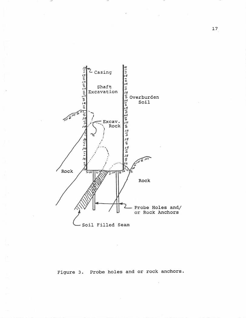
In-hole inspection occurs after the removal of water and
debris. If the integrity of the bearing material is suspect and
the design requires sound rock, a probe hole is drilled by the
contractor. A typical probe hole has a diameter of two inches
and is drilled to a depth of two to three shaft diameters with a
hand operated percussion tool. The probe hole(s), as shown in
Figure 3, is then inspected using a hooked rod to check for
discontinuities such as seams and cavities. While drilling, an
experienced probe hole driller can usually feel discontinuities,
and therefore good communication between the driller and the
inspector is valuable. An excellent reference for inspectors is
the Drilled Shaft Inspector's Manual. Section 3.6 of the manual
describes safety considerations which must be taken, while
section 3.7 describes in-hole checking of the shaft for shafts
bearing in soil and in rock. -rf there are problems with the
bearing stratum, the drilling must continue until reaching
satisfactory material or a design modification must be made.
Design modifications may include a greater value for side
friction if depth and inspection warrant, an increase in shaft
diameter andjor depth, or some other modification.
~ ~ ,,, , ,, -,, -= I If , -Iff -
/If
Rock
Casing
Shaft Excavation
.-' ..
\ . \ .
Ill
= II/ -:: Ill
-Ill
; Overburden Ill ... tj ::. til -::. Ill --Ill ;
Ill -~ ,,, --J/1 --...
Soil
Rock
Probe Holes and/ or Rock Anchors
Filled Seam
Figure 3. Probe holes and or rock anchors.
17
.... ...r· .... ..·
18
After the drilled shaft excavation has passed inspection,
the steel reinforcing cage is placed, and then the concrete is
placed from the surface with a centering device prior to removing
the casing(s). Before , the removal of a casing, the level of
fresh concrete must be enough to overcome hydrostatic pressures
outside the casing. The concrete should have a high slump of 6
to 8 inches to provide good flow characteristics and to fill all
voids left behind the casing. The concrete is placed to the
elevation shown in the plans and the construction of the drilled
shaft foundation is complete. Further details on pulling
temporary casings and placing concrete can be found in section
4.6 of the Drilled Shaft Inspector's Manual.
Wet Construction Method
The wet construction method is used at sites where a dry
excavation cannot be maintained for the placement of the shaft
concrete. This method consists of using water or mineral slurry
to maintain stability of the hole perimeter while advancing the
excavation to the final depth, and placing the reinforcing cage
and shaft concrete. The concrete should have a slump of 7 to 9
inches, and should be placed with a tremie from the bottom of the
excavation upward. The concrete displaces the water/slurry out
of the drilled shaft. While placing the concrete the tremie
remains below the surface of fresh concrete, and any contaminated
. concrete is wasted off the top of the drilled shaft.
Inspection of drilled shafts constructed using the wet
method is difficult. Also contamination of the shaft concrete
19
may occur unnoticed if proper construction procedures are not
followed. The result is that the engineer does not have the same
quality assurance as found in the other construction methods.
This method is typically used in noncohesive soils with a high
water table as in the geology found along the coast. As
mentioned before, details of construction under these conditions
are beyond the scope of this report.
Permanent Casing Construction Method
The permanent casing method works well in caving soils and
over water environments where the casing eliminates the need for
a cofferdam. This method should only be used when required by
the plans. With this method, a casing is driven to a planned
depth before starting the excavation. If full penetration cannot
be attained the engineer may require excavation of material
within the embedded portion of the casing andjor excavation of a
pilot hole ahead of the casing until the casing reaches the
desired penetration.
After excavating to the bottom of the casing, drilling may
stop if the bearing stratum has been reached, or the drilling may
continue using one of the other construction methods to reach the
design bearing stratum. If the shaft is dry, the bearing stratum
and side walls are inspected as previously mentioned. The steel
and concrete is placed as in the casing method, except that the
permanent casing is left in place. Techniques are available
which will allow removal of the casing after the concrete sets,
but this may be more costly than leaving it in place. As
.._..
20
mentioned, this method works well in water crossings where the
casing may work as a form for the bridge column and omit the need
for a cofferdam.
Example: Typical Construction in Alabam~
A typical drilled shaft project in Alabama may consist of
drilling through 30 to 50 ft or more of clay to reach the desired
bearing stratum such as the limestone found in Huntsville. This
section will describe the hypothetical construction of the
foundation to be used in the cost caparison with the actual
driven piles of the I-565-5(22) mainline bridge. Typical rock
excavation for drilled shafts would likely average 5 to 10 ft to
reach sound material. Final shaft diameters of 3.5 feet to 5.0
feet would be specified using a bearing capacity of 100 ksf,
which results in load carrying capacities of 960 kips to 1960
kips in end bearing. Side friction is neglected for purposes of
computing axial capacity.
The contractor begins the excavation using the dry
construction method with an earth auger having a diameter which
is a few inches larger than that of the final bearing as
specified. At the first signs of significant seepage and before
the excavation conditions become unstable, drilling stops and the
auger is removed to allow the placement of a temporary casing.
The casing is then advanced during drilling until the auger meets
refusal, signifying the depth where rock excavation begins. The
auger is then removed and the temporary casing is sealed to the
limestone by a twisting motion to prevent water and debris blow-

.J:"
21
ins. Limestone is difficult and expensive to remove by
mechanical methods, and therefore blasting techniques are
commonly used by local contractors. Using these methods the
excavation can typically proceed at a rate of two to three feet
per drill and shoot. After each blasting, the casing is advanced
and resealed prior to removal of debris. This procedure
continues until reaching "sound" material. A probe hole(s) is
then drilled and inspected as described earlier.
After reaching "sound" rock, the steel reinforcement is
placed and concreting begins. When sufficient concrete is placed
to overcome hydrostatic pressures the casing is slowly pulled
with the bottom of the casing remaining below the top elevation
of the concrete. A drop in the level of concrete may occur as
the concrete fills any voids in the limestone. Concreting
continues as described previously in the casing construction
method. The final volume of the concrete pour may be greater
than the design volume due to the voids in the limestone.
This example shows that an efficient foundation can be
constructed if construction procedures are understood, proper
design methods are used, and proper measures are taken. These
measures include specifications and bid documents which can deal
with the construction and design uncertainties. To ensure
efficient results in construction of drilled shafts and to
eliminate confusion with respect to acceptance criteria, it is
important to develop a good working relationship between the
designer/inspector and the contractor.

•
22
SPECIFICATIONS AND ftiQ DOCUMENTS
Suggested drilled shaft specifications are contained in
Appendix B. The specifications have been developed to mee~ the
geological conditions found in Alabama, and are influenced by
both the experience of local professionals and by the
specifications of the FHWA, ADSC and local designers. Due to the
varied geological conditions of the state, a single specification
covering all conceivable construction situations may be
impossible; special provisions may be required under various
conditions to ensure favorable results. The specifications
include details on all labor, material, equipment and services
necessary to perform all operations in connection with the
drilled shaft installation. Specific details relate to
construction procedures, materials, inspection, testing,
tolerances and payment items. Further details on payment items
and typical bid prices are contained in Appendix c.
A few states use unit costs of unclassified excavation (per
linear foot) and drilled shaft (per linear foot) to include the
following construction costs: earth excavation, rock excavation,
mobilization, concrete and steel reinforcing. When there is
ample subsurface data and the geology is fairly predictable the
two item bid works well. However, this system places an
inordinate risk on the contractor in unpredictable geology where
actual volumes of rock and soil excavations are difficult to
predict. The result is inflated bids by the contractors to cover
the worst possible situation and to ensure a profit. A more
reasonable approach is to include a unit cost for each item as
follows:
·earth excavation (per linear foot), •rock excavation (per linear foot), •mobilization (lump sum), ·concrete (per cubic yard by dray ticket) and ·steel reinforcing (per pound).
23
This method does not burden bidders with the full risk of unknown
subsurface conditions and results in lower overall bids.
Situations such as these exist in karstic and pinnacle formations
(as found in some areas of Birmingham), where it is difficult to
obtain complete subsurface data. Some shortcomings of this
bidding practice include the fact that a final cost for a project
is not known prior to the start of construction. In addition, it
is difficult to provide a clear and precise definition of earth
and rock excavation. One definition, commonly used, is that rock
excavation is any material which can not be removed at the time
rate of 60 minutes per foot with a Hughes LDH or equal drill with
a minimum down-thrust of 30,000 pounds.
The two item bid, items for excavation and shaft length, is
appropriate when substantial geological data is available and the
geology is relatively uniform. Under such circumstances, the
contractor can make a bid with reliable quantity estimates and
the need for a definition of earth and rock excavation is
diminished. These conditions may be present in areas such as the
selma chalk of central Alabama and much of the shale and
sandstone areas of the Paleozoic Region of north Alabama. In

other parts of Alabama it is important to have a bid document
which can be expanded beyond the two item bid. This type bid
document is found in Appendix c. of this report.
24
25
COST COMPARISON
A cost comparison of drilled shaft foundations versus driven
pile foundations was performed on the recently completed (I-565-
5(22)] mainline bridge project in Huntsville. For simplicity,
only the mainline structure was used in calculations and
miscellaneous ramp bridges were ignored in cost computations for
both driven piles and drilled shaft. Calculations were made
using a personal computer with the spread sheet LOTUS 123, and
the results are contained in Appendix D. The cost of the driven
pile foundations was calculated from actual/ construction bids
used to construct the bridge. The cost of the drilled shaft
foundations was calculated using typical costs obtained from
local drilled shaft contractors on actual commercial projects in
similar geology.
Two separate design calculations where made for the drilled
shaft foundations. The firs~ design is based on "sound"
limestone with an end bearing capacity of 100 ksf, and the second
design is based on poor limestone conditions or other bedrock
such as sandstone with an end bearing capacity of 60 ksf. The
actual Huntsville site appears to be more like the sound
limestone, but the less favorable condition was also evaluated as
a comparison. The total cost of the mainline foundations using
driven piles is $2,421,714. The savings by using drilled shaft
foundations is calculated to be 40.35% ($977,76) for drilled
shafts with an end bearing of 100 ksf and 18.21% ($440,954) for

26
an end bearing of 60 ksf.
Note that a true cost comparison will not be ·possible until
drilled shaft foundations are used as a design alternate and the
resulting foundation bids of both driven piles and drilled shafts
can then be compared. Furthermore, costs to the state for
additional design, training and inspection have not been
considered in the cost comparison.
Cost Procedure ~ Driven Piles
The cost comparison begins with calculations of costs of
concrete pile caps needed for load transfer in driven pile
foundations. The plans are used to obtain quantities of concrete
and steel reinforcement. Actual costs for these items come from
the low bid at $160.00 per yard of concrete and $0.38 per pound
of steel. Depending on the size of the pile cap the costs range
from $2,065 to $28,048 as shown in Appendix D.
The cost of driven H-piles is $22.00 per foot according to
the bid documents. This value is multiplied by the depth to
bedrock (Fort Payne Chert and Tuscumbia Limestone) as specified
from the soil borings. The length is then multiplied by the
number of piles used in the foundation. By adding in the cost of
the pile cap and multiplying by the number of pile groups, the
cost of driven pile foundations is calculated at each bent
number. The costs of all bents on the mainline are summed
together, and the total cost of $2,421,714 results.
,,,,
27
Cost Procedure ~ Drilled Shafts
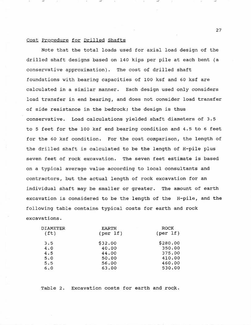
Note that the total loads used for axial load design of the
drilled shaft designs based on 140 kips per pile at each bent (a
conservative approximation). The cost of drilled shaft
foundations with bearing capacities of 100 ksf and 60 ksf are
calculated in a similar manner. Each design used only considers
load transfer in end bearing, and does not consider load transfer
of side resistance in the bedrock; the design is thus
conservative. Load calculations yielded shaft diameters of 3.5
to 5 feet for the 100 ksf end bearing condition and 4.5 to 6 feet
for the 60 ksf condition. For the cost comparison, the length of
the drilled shaft is calculated to be the length of H-pile plus
seven feet of rock excavation. The seven feet estimate is based
on a typical average value according to local consultants and
contractors, but the actual length of rock excavation for an
individual shaft may be smaller or greater. The amount of earth
excavation is considered to be the length of the H-pile, and the
following table contains typical costs for earth and rock
excavations.
DIAMETER EARTH ROCK (ft) (per lf) (per lf)
3.5 $32.00 $280.00 4.0 40.00 350.00 4.5 44.00 375.00 5.0 50.00 410.00 5.5 56.00 460.00 6.0 63.00 530.00
Table 2. Excavation costs for earth and roc~.

28
To arrive at the total cost per drilled shaft the costs of
concrete, steel and probe holes are added to the cost of
excavation. The volume of concrete is calculated as 1.5 times
the volume of excavation, allowing for concrete loss to overbreak
at a cost of $55.00 per cubic yard. The amount of reinforcing
steel is estimated at 0.75% of the cross sectional area of
drilled shaft and is considered continuous for the entire length
at a cost of $0.45 per pound. Each drilled shaft is also
estimated to have an 8 foot probe hole in the base at $18.00 per
foot.
The total cost for the entire drilled shaft foundation
project results by summing the costs at each bent number and
adding $50,000 for mobilization costs. This cost for
mobilization along with the other construction costs used are a
result of typical construction values used by local drilling
contractors for a project of this size; the values used are shown
in Appendix c. The total cost of the drilled shaft foundations
is $1,444,638 with an end bearing of 1000 ksf and $1,980,760 with
an end bearing of 60 ksf.
29
CONCLUSIONS
The cost savings, high load carrying capability and
experience of local contractors make drilled shafts an attractive
alternative to driven piles for bridge foundations in many areas
of the state of Alabama. It is recommended that implementation
of drilled shafts be initiated by providing them as an alternate
to driven piles on several projects where shafts are likely to be
competitive and construction difficulties are not likely to be
sev~re. This will give drilled shafts a chance to compete
directly with driven piles. As the Alabama Highway Department
gains experience in design, construction and inspection, drilled
shafts may then be used under more difficult field and geological
conditions. It is also recommended that, before using drilled
shafts in unfamiliar geological conditions, a field test shaft
should be constructed and load tested if possible to gain added
design and construction experience.

30
REFERENCES
1. American Concrete Institute, "Standard Specification for the Construction of End Bearing Drilled Piers," ACI 336.1-79, 1985.
2. Association of Drilled Shaft Contractors, standards and Specifications for the Foundation Drilling Industry, November 1988.
3. Brown, D. A., "Construction and Design of Drilled Shafts in Hard Pinnacle Limestones," Transportation Research Record, in print.
4. Deep Foundations Institute and the Association of Drilled Shaft Contractors, Drilled Shaft Inspectors Manual, Fourth Revision.
5. Federal Highway Administration, Drilled Shafts; Construction Procedures and Design Methods, Publication No. FHWA-HI-88-042, July 1988.
6. Florida Department of Transportation, Section 455, "Standard Specifications for Road and Bridge Construction," Edition of 1982, State Highway Foundation Speci'fications, Eastern Edition.
7. Geological survey of Alabama, Engineering Geology of Jefferson County, Atlas 14, University of Alabama, 1979.
8. Szabo, M. w., w. E. Osborne, and C. W. Copeland, Geologic Map of Alabama, Special Map 220, 1988.
9. Tolson, J.s., Guide to Alabama Geology, Geological Society of America, March 1972.
APPENDICES
Appendix A.
Appendix B.
Appendix c.
Appendix D.
...:11 "
Design Procedure and Sample Calculations.
Suggested Specifications.
Bid Documents.
Cost Comparison.
31
.... ....
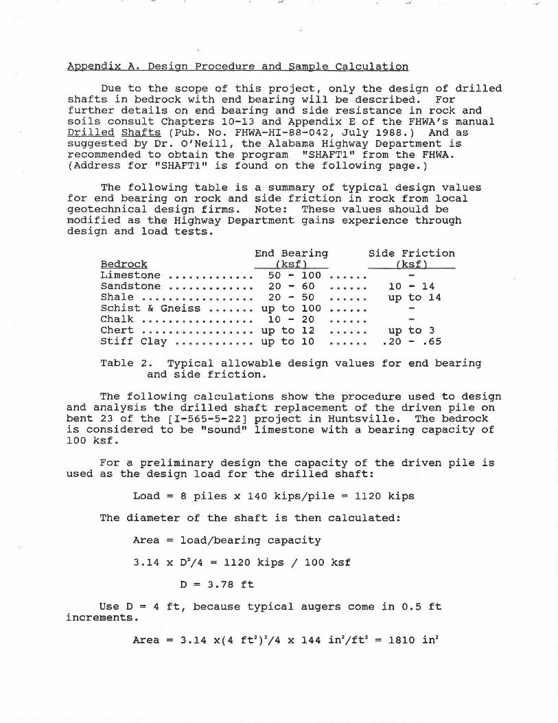
Appendix A. Design Procedure and Sample Calculation
Due to the scope of this project, only the design of drilled shafts in bedrock with end bearing will be described. For further details on end bearing and side resistance in rock and soils consult Chapters 10-13 and Appendix E of the FHWA's manual Drilled Shafts (Pub. No. FHWA-HI-88-042, July 1988.) And as suggested by Dr. O'Neill, the Alabama Highway Department is recommended to obtain the program 11 SHAFT1" from the FHWA. (Address for . "SHAFT1" is found on the following page.)
The following table is a summary of typical design values for end bearing on rock and side friction in rock from local geotechnical design firms. Note: These values should be modified as the Highway Department gains experience through design and load tests.
Begrock Limestone . . . . . . . . . . . . . Sandstone . . . . . . . . . . . . . Shale ................. Schist & Gneiss . . . . . . . Chalk ................. Chert .......... Ill •••••••
Stiff Clay ............
End Bearing (ksf)
50 - 100 20 - 60 20 - 50
up to 100 10 - 20
up to 12 up to 10
......
. . . . . .
. .....
. . . . . .
. .....
. .....
. .....
Side Friction Cksf)
10 - 14 up to 14
up to 3 .20 - .65
Table 2. Typical allowable design values for end bearing and side friction.
The following calculations show the procedure used to design and analysis the drilled shaft replacement of the driven pile on bent 23 of the [I-565-5-22] project in Huntsville. The bedrock is considered to be "sound" limestone with a bearing capacity of 100 ksf.
For a preliminary design the capacity of the driven pile is used as the design load for the drilled shaft:
Load = 8 piles x 140 kips/pile = 1120 kips
The diameter of the shaft is then calculated:
Area = loadjbearing capacity
3.14 x D2/4 = 1120 kips 1 100 ksf
D = 3.78 ft
Use D = 4 ft, because typical augers come in 0.5 ft increments.
.... .... ..
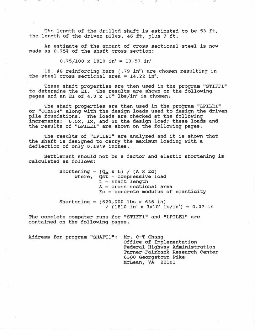
The length of the drilled shaft is estimated to be 53 ft, the length of the driven piles, 46 ft, plus 7 ft.
An estimate of the amount of cross sectional steel is now made as 0.75% of the shaft cross section:
o. 751100 x 1810 in2 = 13.57 in2
18, #8 reinforcing bars (.79 in2) are chosen resulting in
the steel cross sectional area = 14.22 in2•
These shaft properties are then used in the program "STIFFl" to determine the EI. The results are shown on the following pages and an EI of 4. o x 1011 lbslin2 is chosen.
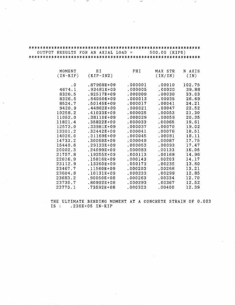
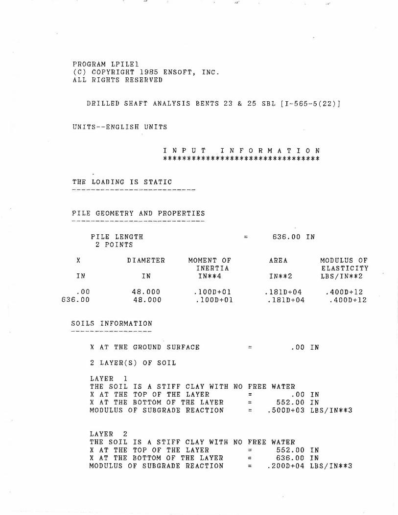
The shaft properties are then used in the program "LPILE1" or "COM624" along with the design loads used to design the driven pile foundations. The loads are checked at the following increments: 0.5x, lx, and 2x the design load; these loads and the results of "LPILE1" are shown on the following pages.
The results of "LPILE1" are analyzed and it is shown that the shaft is designed to carry the maximum loading with a deflection of only 0.1849 inches.
Settlement should not be a factor and elastic shortening is calculated as follows:
Shortening = where,
(Qrt x L) I (A x Ec) Qst = compressive load L = shaft length A = cross sectional area Ec = concrete modulus of elasticity
Shortening = (620,000 lbs x 636 in) 1 ( 1810 in 2 x 3xlO' lblin2
) = o. 07 in
The complete computer runs for "STIFF1" and "LPILE1" are contained on the following pages.
Address for program "SHAFT1": Mr. C-T Chang Office of Implementation Federal Highway Administration Turner-Fairbank Research Center 6300 Georgetown Pike McLean, VA 22101

************************************************************* DRILLED SHAFT ANALYSIS BENTS 23 & 25 SBL (I-565-5-(22)]
*************************************************************
DIANETER = 48.00 IN ..
CONCRETE COMPRESSIVE STRENGTH = 3.50 KSI
REBARS YIELD STRENGTH = 60.00 KSI
MODULUS OF ELASTICITY OF STEEL = 29000.00 KSI
NUMBER OF REINFORCING BARS = 18
NUMBER OF ROWS OF REINFORCING BARS = 9
COVER THICKNESS = 3.50 IN.
SQUASH LOAD CAPACITY = 6194.33 KIPS
ROW AREA OF DISTANCE TO NUMBER REINFORCEMENT CENTROIDAL AXIS
(SQ. IN.) (IN.)
1 1. 58 20.19 2 1. 58 17.75 3 1. 58 13.18 4 1. 58 7.01 5 1. 58 .00 6 1. 58 -7.01 7 1. 58 -13.18 8 1. 58 -17.75 9 1. 58 -20.19
.. ·
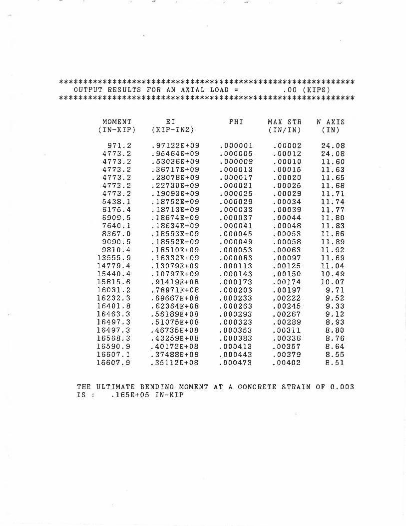
************************************************************* OUTPUT RESULTS FOR AN AXIAL LOAD = .00 (KIPS)
*************************************************************
MOMENT EI PHI MAX STH N AXIS (IN-KIP) (KIP-IN2) (IN/IN) (IN)
971.2 .97122E+09 .000001 .00002 24.08 4773.2 .95464E+09 .000005 .00012 24.08 4773.2 .53036E+09 .000009 .00010 11.60 4773.2 .36717E+09 .000013 .00015 11.63 4773.2 .28078E+09 .000017 .00020 11.65 4773.2 .22730E+09 .000021 .00025 11.68 4773.2 .19093E+09 .000025 .00029 11. 71 5438.1 .18752E+09 .000029 .00034 11.74 6175.4 .18713E+09 .000033 .00039 11.77 6909.5 .18674E+09 .000037 .00044 11.80 7640.1 .18634E+09 .000041 .00048 11.83 8367.0 .18593E+09 .000045 .00053 11.86 9090.5 .18552E+09 .000049 .00058 11.89 9810.4 .18510E+09 .000053 .00063 11.92
13555.9 .16332E+09 .000083 .00097 11.69 14779.4 .13079E+09 .000113 .00125 11.04 15440.4 .10797E+09 .000143 .00150 10.49 15815.6 .91419E+08 .000173 .00174 10.07 16031.2 .78971E+08 .000203 .00197 9.71 16232.3 .69667E+08 .000233 .00222 9.52 16401.8 .62364E+08 .000263 .00245 9.33 16463.3 .56189E+08 .000293 .00267 9.12 16497.3 .51075E+08 .000323 .00289 8.93 16497.3 .46735E+08 .000353 .00311 8.80 16568.3 .43259E+08 .000383 .00336 8.76 16590.9 .40172E+08 .000413 .00357 8.64 16607.1 .37488E+08 .000443 .00379 8.55 16607.9 .35112E+08 .000473 .00402 8.51
THE ULTIMATE BENDING MOMENT AT A CONCRETE STRAIN OF 0.003 IS . .165E+05 IN-KIP .

************************************************************* OUTPUT RESULTS FOR AN AXIAL LOAD = 250.00 (KIPS)
*************************************************************
MOMENT (IN-KIP)
921.0 4747.3 4747.3 5335.2 6142.7 6915.2 7671.2 8416.6 9148.1 9877.9
10596.6 11311.0 12024.7 12728.1 16932.7 18491. 1 19184.6 19731.0 19914.5 20098.6 20232.5 20361.7 20444.3 20452.2 20452.2
EI (KIP-IN2)
.92102E+09
.94947E+09
.52748E+09
.41040E+09
.36133E+09
.32930E+09
.30685E+09
.29023E+09
.27721E+09
.26697E+09
.25845E+09
.25136E+09
.24540E+09
.24015E+09
.20401E+09
.16364E+09
.13416E+09
.11405E+09
.98101E+08
.86260E+08
.76930E+08
.69494E+08
.63295E+08
.57938E+08
.53400E+08
PHI
.000001
.000005
.000009
.000013
.000017
.000021
.000025
.000029
.000033
.000037
.000041
.000045
.000049
.000053
.000083
.000113
.000143
.000173
.000203
.000233
.000263
.000293
.000323
.000353
.000383
MAX S.TR (IN/IN)
.00006
.00016
.00021
.00027
.00032
.00038
.00043
.00048
.00053
.00058
.00064
.00069
.00074
.00079
.00116
.00148
.00177
.00207
.00234
.00261
.00289
.00317
.00346
.00374
.00401
N AXIS (IN)
63.09 31.95 23.40 20.68 19.06 17.96 17.19 16.62 16.15 15.81 15.51 15.27 15.09 14.91 14.01 13.11 12.40 11.97 11.51 11.20 11.00 10.81 10.71 10.58 10.47
THE ULTIMATE BENDING MOMENT AT A CONCRETE STRAIN OF 0.003 IS : .203E+05 IN-KIP
,J"
************************************************************* OUTPUT RESULTS FOR AN AXIAL LOAD = 500.00 (KIPS)
*************************************************************
MOMENT EI PHI MAX STR N AXIS (IN-KIP) (KIP-IN2) (IN/IN) (IN)
. 0 .87968E+09 .000001 .00010 102.75 4674.1 .93481E+09 .000005 .00020 39.88 8326.5 .92517E+09 .000009 .00030 33.03 8326.5 .64050E+09 .000013 .00035 26.69 8524.7 .50145E+09 .000017 .00041 24.21 9420.9 .44862E+09 .000021 .00047 22.52
10258.2 .41033E+09 .000025 .00053 21.30 11052.0 .38110E+09 .000029 .00059 20.35 11821.4 .35822E+09 .000033 .00065 19.61 12573.0 .33981E+09 .000037 .00070 19.02 13301.2 .32442E+09 .000041 .00076 18.51 14026.0 .31169E+09 .000045 .00081 18.11 14733.2 .30068E+09 .000049 .00087 17.75 15440.6 .29133E+09 .000053 .00093 17.47 20002.3 .24099E+09 .000083 .00133 16.05 21757.8 .19255E+09 .000113 .00169 14.96 22616.9 .15816E+09 .000143 .00203 14.17 23112.9 .13360E+09 .000173 .00235 13.60 23467.7 .11560E+09 .000203 .00268 13.21 23604.8 .10131E+09 .000233 .00299 12.85 23683.2 .90050E+08 .000263 .00334 12.70 23730.7 .80992E+08 .000293 .00367 12.52 23770.1 .73592E+08 .000323 .00400 12.39
THE ULTIMATE BENDING MOMENT AT A CONCRETE STRAIN OF 0.003 IS : .236E+05 IN-KIP
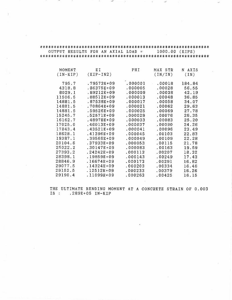
************************************************************* OUTPUT RESULTS FOR AN AXIAL LOAD = 1000.00 (KIPS)
*************************************************************
tv10MENT EI PHI MAX STR N AXIS (IN-KIP) (KIP-IN2) (IN/IN) (IN)
795.7 .79573E+09 .000001 .00018 184.84 4318.8 .86375J?+09 .000005 .00028 56.55 8029.1 .89212E+09 .000009 .00038 42.19
11506.5 .88512E+09 .000013 .00048 36.85 14881.5 .87538E+09 .000017 .00058 34.07 14881.5 .70864E+09 .000021 .00062 29.63 14881.5 .59526E+09 .000025 .00069 27.78 15245.7 .52571E+09 .000029 .00076 26.35 16162.7 .48978E+09 .000033 .00083 25.20 17025.0 .46013E+09 .000037 .00090 24.26 17843.4 .43521E+09 .000041 .00096 23.49 18628.1 .41396E+09 .000045 .00103 22.83 19387.1 .39566E+09 .000049 .00109 22.28 20104.6 .37933E+09 .000053 .00115 21.78 25022.2 .30147E+09 .000083 .00163 19.59 27393.2 .24242E+09 .000113 .00207 18.32 28398.1 .19859E+09 .000143 .00249 17.43 28846.9 .16674E+09 .000173 .00291 16.82 29077.5 .14324E+09 .000203 .00334 16.46 29152.5 .12512E+09 .000233 .00379 16.26 29190.4 .11099E+09 .000263 .00425 16.15
THE ULTIMATE BENDING MOMENT AT A CONCRETE STRAIN OF 0.003 IS .289E+05 IN-KIP
.a· ....
PROGRAM LPILEl (C) COPYRIGHT 1985 ENSOFT, INC. ALL RIGHTS RESERVED
.os· ...
DRILLED SHAFT ANALYSIS BENTS 23 & 25 SBL [I-565-5(22)}
UNITS--ENGLISH UNITS
I N P U T I N F 0 R M A T I 0 N *********************************
THE LOADING IS STATIC
PILE GEOMETRY AND PROPERTIES
PILE LENGTH = 636.00 IN 2 POINTS
X DIAMETER MOMENT OF AREA INERTIA
IN IN IN**4 IN**2
.00 48.000 .lOOD+Ol .181D+04 636.00 48.000 .lOOD+Ol .181D+04
SOILS INFORMATION
X AT THE GROUND SURFACE = .00 IN
2 LAYER(S) OF SOIL
LAYER 1 THE SOIL IS A STIFF CLAY WITH NO FREE WATER X AT THE TOP OF THE LAYER = .00 IN X AT THE BOTTOM OF THE LAYER = 552.00 IN
MODULUS OF ELASTICITY LBS/IN**2
.400D+l2 .400D+l2
MODULUS OF SUBGRADE REACTION = .500D+03 LBS/IN**3
LAYER 2 THE SOIL IS A STIFF CLAY WITH NO FREE WATER X AT THE TOP OF THE LAYER = 552.00 IN X AT THE BOTTOM OF THE LAYER = 636.00 IN MODULUS OF SUBGRADE REACTION = .200D+04 LBS/IN**3

DISTRIBUTION OF EFFECTIVE UNIT WEIGHT WITH DEPTH
X, IN
. 00 552.00 552.00 636.00
4 POINTS
WEIGHT,LBS/IN**3
.70D-01
.70D-01
.87D-01
.87D-01
DISTRIBUTION OF STRENGTH PARAMETERS WITH DEPTH 4 POINTS
X, IN C,LBS/IN**2
.00 .833D+01 552.00 .833D+01 552.00 .556D+02 636.00 .556D+02
BOUNDARY AND LOADING CONDITIONS
LOADING NUMBER 1
BOUNDARY-CONDITION CODE LATERAL LOAD AT THE PILE HEAD MOMENT AT THE PILE HEAD AXIAL LOAD AT THE PILE HEAD
LOADING NUMBER 2
BOUNDARY-CONDITION CODE LATERAL LOAD AT THE PILE HEAD MOMENT AT THE PILE HEAD AXIAL LOAD AT THE PILE HEAD
LOADING NUMBER 3
BOUNDARY-CONDITION CODE LATERAL LOAD AT THE PILE HEAD MOMENT AT THE PILE HEAD AXIAL LOAD AT THE PILE HEAD
PHI,DEGREES E50
.000 .700D-02
.000 .700D-02
.000 .400D-02
.000 .400D-02
= 1 = .260D+05 LBS = .330D+06 IN-LBS = • 620D+06 LBS
= 1 = . 520D+05 LBS = .660D+06 IN-LBS = . 620D+06 LBS
= 1 = .1040+06 LBS = .132D+07 IN-LBS = . 620D+06 LBS
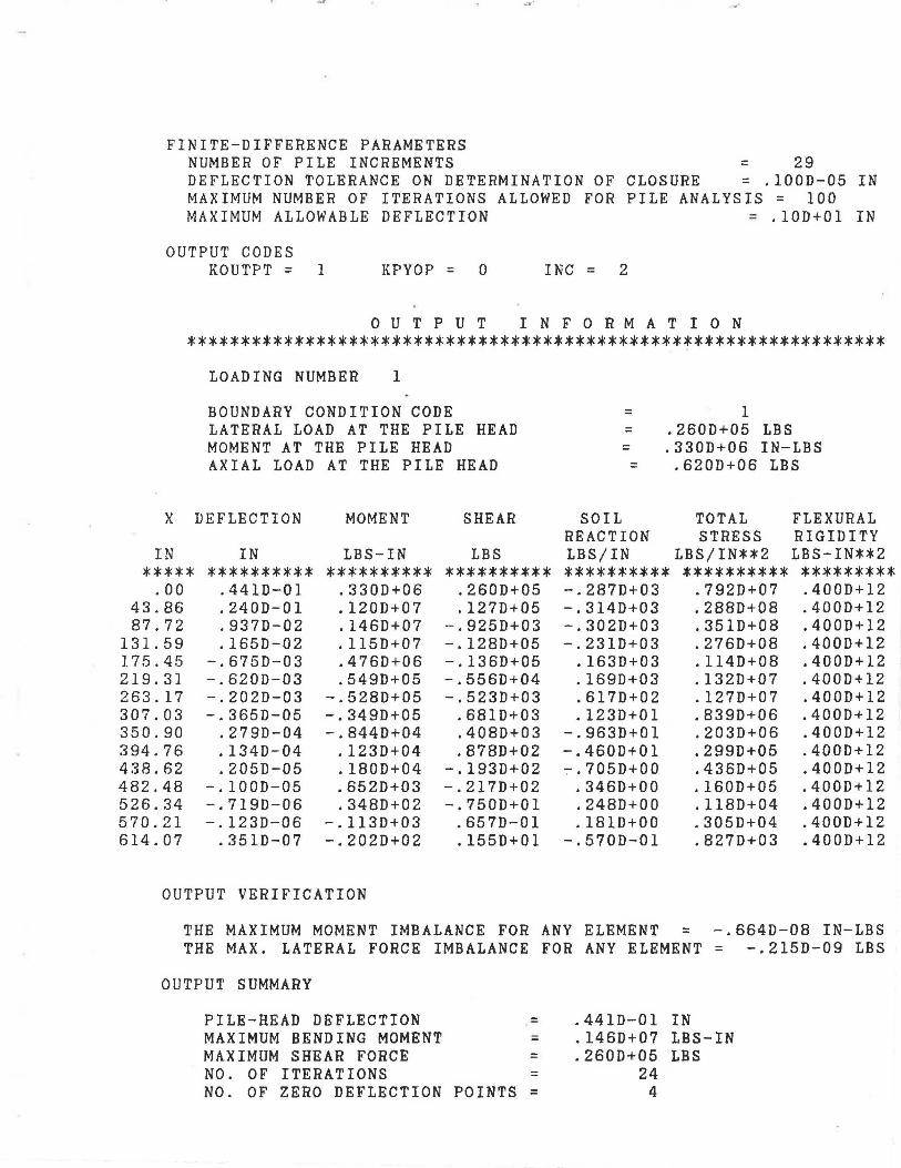
FINITE-DIFFERENCE PARAMETERS NUMBER OF PILE INCREMENTS = 29 DEFLECTION TOLERANCE ON DETERMINATION OF MAXIMUM NUMBER OF ITERATIONS ALLOWED FOR MAXIMUM ALLOWABLE DEFLECTION
CLOSURE = .100D-05 IN PILE ANALYSIS = 100
= .10D+01 IN
OUTPUT CODES KOUTPT = 1 KPYOP = 0 INC = 2
0 U T P U T I N F 0 R M A T I 0 N *****************************************************************
X
IN *****
.00 43.86 87.72
131.59 17.5.45 219.31 263.17 307.03 350.90 394.76 438.62 482.48 526.34 570.21 614.07
LOADING NUMBER 1
BOUNDARY CONDITION CODE LATERAL LOAD AT THE PILE HEAD MOMENT AT THE PILE HEAD AXIAL LOAD AT THE PILE HEAD
DEFLECTION
IN **********
.441D-01
.240D-01
.937D-02
.165D-02 -.675D-03 -.620D-03 -.202D-03 -.365D-05
.279D-04
.1340-04
.205D-05 -.100D-05 -.719D-06 -.123D-06
.351D-07
MOMENT
LBS-IN **********
.330D+06
.120D+07
.1460+07
.115D+07
.476D+06
.549D+05 -.528D+05 -.349D+05 -.8440+04
.123D+04
.1800+04
.652D+03
.348D+02 -.113D+03 -.202D+02
SHEAR
LBS **********
.260D+05
.127D+05 -.9250+03 -.1280+05 -.1360+05 -.556D+04 -.5230+03
.6810+03
.408D+03
.878D+02 -.193D+02 -.2170+02 -.7500+01
.657D-01
.1550+01
OUTPUT VERIFICATION
= 1 = . 260D+05 LBS = .330D+06 IN-LBS = • 620D+06 LBS
SOIL TOTAL FLEXURAL REACTION STRESS RIGIDITY LBS/IN LBS/IN**2 LBS-IN**2 ********** ********** ********* -.287D+03 .7920+07 .400D+12 -.314D+03 .2880+08 .400D+12 -.302D+03 .3510+08 .400D+12 -.2310+03 .276D+08 .4000+12
.163D+03 .114D+08 .4000+12
.169D+03 .132D+07 .400D+12
.617D+02 .127D+07 .400D+12
.1230+01 .839D+06 .400D+12 -.963D+01 .203D+06 .400D+12 -.460D+01 .299D+05 .400D+12 ~.705D+OO .436D+05 .400D+12
.346D+OO .160D+05 .400D+12
.248D+OO .1180+04 .400D+12
.181D+00 .305D+04 .400D+12 -.570D-01 .827D+03 .400D+12
THE MAXIMUM MOMENT IMBALANCE FOR ANY ELEMENT = -.664D-08 IN-LBS THE MAX. LATERAL FORCE IMBALANCE FOR ANY ELEMENT = -.215D-09 LBS
OUTPUT SUMMARY
PILE-HEAD DEFLECTION = MAXIMUM BENDING MOMENT = MAXIMUM SHEAR FORCE = NO. OF ITERATIONS = NO. OF ZERO DEFLECTION POINTS =
.441D-01 IN
.146D+07 LBS-IN
.2600+05 LBS 24
4
X
IN *****
.00 43.86 87.72
131.59 175.45 219.31 263.17 307.03 350.90 394.76 438.62 482.48 526.34 570.21 614.07•
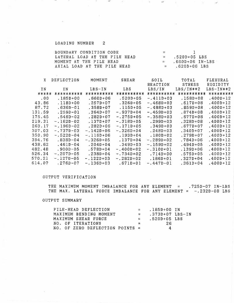
LOADING NUMBER 2
BOUNDARY CONDITION CODE LATERAL LOAD AT THE PILE HEAD MOMENT AT THE PILE HEAD AXIAL LOAD AT THE PILE HEAD
DEFLECTION MOMENT SHEAR
IN LBS-IN LBS ********** ********** **********
.185D+OO .660D+06 .520D+05
.1180+00 .2570+07 .3260+05
.6360-01 .3580+07 .1150+05
.2590-01 .3640+07 -.9370+04
.5460-02 .2820+07 -.2750+05 -.1620-02 .1370+07 -.3180+05 -.1960-02 .2820+06 -.1710+05 -.7370-03 -.142D+06 -.3260+04 -.522D-04 -.116D+06 .1930+04
.838D-04 -.3260+05 .1370+04
.4610-04 .2040+04 .3490+03
.9000-05 .578D+04 -.4000+02 -.2070-05 .238D+04 -.7340+02 -.1270-05 -.1220+03 -.2820+02
.276D-07 -.1360+03 .6710+01
OUTPUT VERIFICATION
.... .~·
= 1 = .520D+05 LBS = .660D+06 IN-LBS
::: .6200+06 LBS
SOIL TOTAL FLEXURAL REACTION STRESS RIGIDITY LBS/IN LBS/IN**2 LBS-IN**2 ********** ********** ********* -.4110+03 .1580+08 .400D+l2 -.4680+03 .6170+08 .4000+12 -.4880+03 .8590+08 .4000+12 -.4590+03 .8740+08 .4000+12 -.3580+03 .6770+08 .4000+12
. 2990+0.3 .3280+08 .4000+12
.3490+03 .6770+07 .4000+12
.2480+03 .3400+07 .4000+12
.1800+02 .2790+07 .400D+12 -.2890+02 .7840+06 .400D+12 -.1590+02 .494D+05 .400D+12 -.310D+01 .1390+06 .4000+12
.7140+00 .5750+05 .4000+12
.186D+01 .3270+04 .4000+12 -.447D-01 .361D+04 .4000+12
THE MAXIMUM MOMENT IMBALANCE FOR ANY ELEMENT = .725D-07 IN-LBS THE MAX. LATERAL FORCE IMBALANCE FOR ANY ELEMENT = -.232D-08 LBS
OUTPUT SUMMARY
PILE-HEAD DEFLECTION = MAXIMUM BENDING MOMENT = MAXIMUM SHEAR FORCE = NO. OF ITERATIONS = NO. OF ZERO DEFLECTION POINTS =
.185D+OO IN
.373D+07 LBS-IN
.5200+05 LBS 26
4

_.,.
LOADING NUMBER 3
BOUNDARY CONDITION CODE :: 1 LATERAL LOAD AT THE PILE HEAD = .104D+06 LBS MOMENT AT THE PILE HEAD = .1320+07 IN-LBS AXIAL LOAD AT THE PILE HEAD = .620D+06 LBS
X DEFLECTION MOMENT SHEAR SOIL TOTAL FLEXURAL REACTION STRESS RIGIDITY
IN IN LBS-IN LBS LBS/IN LBS/IN**2 LBS-IN**2 ***** ********** ********** ********** ********** ********** ********* .oo .782D+OO .132D+07 .1040+06 -.589D+03 .317D+08 .400D+12
43.86 .5610+00 .5430+07 .7580+05 -.6910+03 .130D+09 .400D+12 87.72 .3650+00 .8190+07 .4400+05 -.7550+03 .197D+09 .400D+12
131.59 .209D+00 .948D+07 .103D+05 -.7730+03 .228D+09 .400D+12 175.45 .976D-01 .927D+07 -.229D+05 -.7360+03 .222D+09 .4000+12 219.31 .305D-01 .762D+07 -.5300+05 -.622D+03 .183D+09 .400D+12 263.17 -.415D-03 .477D+07 -.696D+05 .1270+03 .114D+09 .400D+12 307.03 -.829D-02 .202D+07 -.514D+05 .553D+03 .484D+08 .4000+12 350.90 -.615D-02 .297D+06 -.273D+05 .526D+03 .713D+07 .400D+12 394.76 -.227D-02 -.419D+06 -.656D+04 .410D+03 .101D+08 .400D+12 438.62 -.175D-03 -.355D+06 .573D+04 .605D+02 .851D+07 .400D+12 482.48 . 250D-'03 -.102D+06 .419D+04 -.862D+02 .245D+07 .400D+12 526.34 .135D-03 .532D+04 .114D+04 -.465D+02 .128D+06 .400D+12 570.21 .184D-04 .222D+05 -.160D+03 -.271D+02 .533D+06 .400D+12 614.07 -.698D-05 .338D+04 -.278D+03 .113D+02 .815D+05 .400D+12
OUTPUT VERIFICATION
THE MAXIMUM MOMENT IMBALANCE FOR ANY ELEMENT = .552D-06 IN-LBS THE MAX. LATERAL FORCE IMBALANCE FOR ANY ELEMENT= .151D-07 LBS
OUTPUT SUMMARY
PILE-HEAD DEFLECTION = MAXIMUM BENDING MOMENT = MAXIMUM SHEAR FORCE = NO. OF ITERATIONS = NO. OF ZERO DEFLECTION POINTS =
.782D+OO IN
.956D+07 LBS-IN
.104D+06 LBS 28
3

BOUNDARY BOUNDARY CONDITION CONDITION
BC1 BC2
.2600D+05 .3300D+06
.5200D+05 .6600D+06
.1040D+06 .13200+07
S U M M A R Y T A B L E *************************
AXIAL PILE HEAD . LOAD DEFLECTION
LBS IN
.6200D+06 .4411D-01
.62000+06 .18490+00
.6200D+06 .78170+00
MAX . MAX. MOMENT SHEAR IN-LBS LBS
.1463D+07 .2600D+0 -
.37270+07 .52000+C
.95610+07 .10400+0
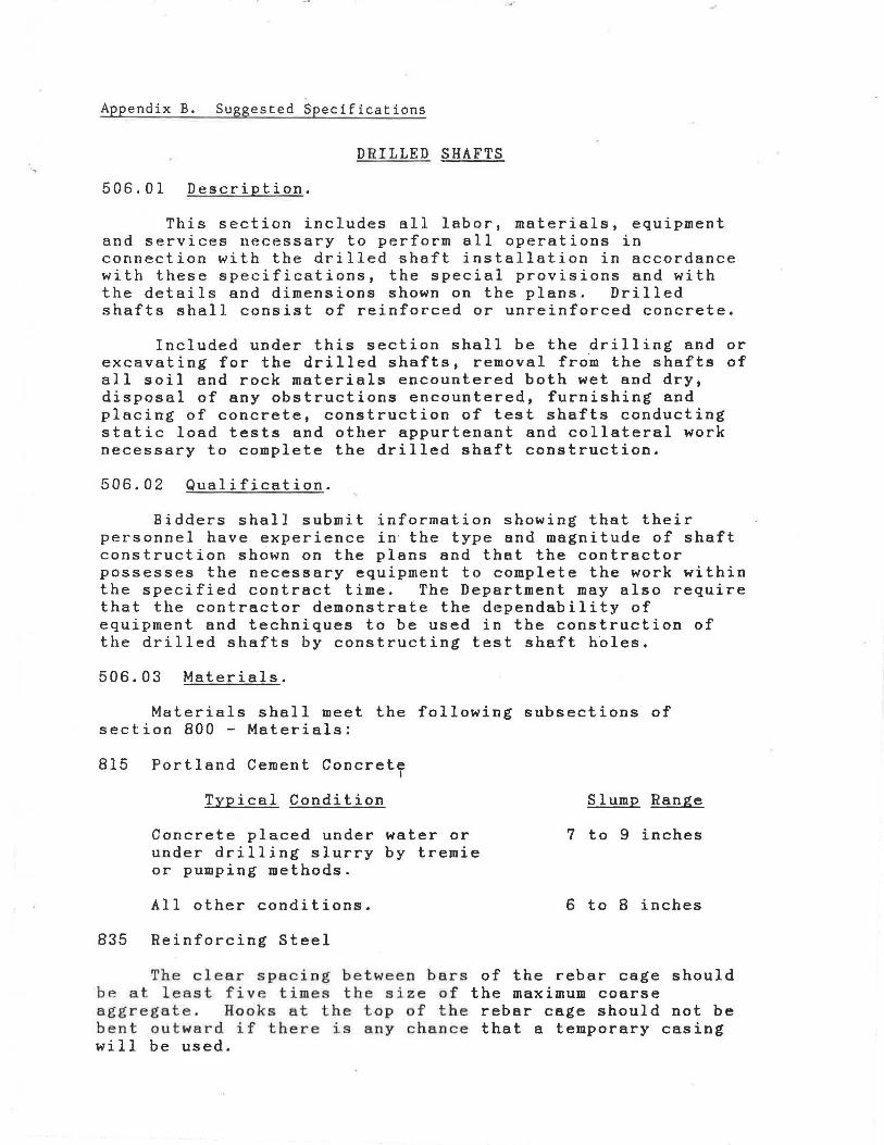
Appendix B. Suggested Specifications
DRILLED SHAFTS
506.01 Description.
This section includes all labor, materials, equipment and services necessary to perform all operations in connection with the drilled shaft installation in accordance with these specifications, the special provisions and with the details and dimensions shown on the plans. Drilled shafts shall consist of reinforced or unreinforced concrete.
Included under this section shall be the drilling and or excavating for the drilled shafts, removal fro~ the shafts of all soil and rock materials encountered both wet and dry, disposal of any obstructions encountered, furnishing and placing of concrete, construction of test shafts conducting static load tests and other appurtenant and collateral work necessary to complete the drilled shaft construction.
506.02 Qualification.
Bidders shall submit information showing that their personnel have experience in· the type and magnitude of shaft construction shown on the plans and that the contractor possesses the necessary equipment to complete the work within the specified contract time. The Department may also require that the contractor demonstrate the dependability of equipment and techniques to be used in the construction of the drilled shafts by constructing test sha£t h~les.
506.03 Materials.
Materials shall meet the following subsections of section 800 - Materials:
815 Portland Cement Concret~
Typical Condition
Concrete placed under water or under drilling slurry by tremie or pumping methods.
All other conditions.
835 Reinforcing Steel
Slump Range
7 to 9 inches
6 to 8 inches
The clear spacing between bars of the rebar cage should be at least five times the size of the maximum coarse aggregate. Hooks at the top of the rebar cage should not be bent outward if there is any chance that a temporary casing will be used.

506.04 Construction Methods and Equipment.
(a) Protection of Existing Structures.
The contractor shall take all reasonable precautions to prevent damage to existing structures and utilities. These measures shall include, but are not limited to, selecting construction methods and procedures that will prevent excessive caving of the shaft excavation, monitoring and controlling t~e vibrations from construction activities such as driving of casing or sheeting, drilling of the shaft, or from blasting.
(b) Construction Sequence.
All excavation of the foundations in which drilled shafts are to be constructed shall be completed before shaft construction begins. After shaft construction is completed all loose or displaced materials shall be removed from around the shafts, leaving a clean solid surface to receive the footing concrete.
(c) Drilled Shaft Installation Plan.
No later than one month prior to constructing drilled shafts, the contractor shall submit a installation plan for approval by the engineer. This plan shall provide information on the following:
1. Name and experience record of the drilled shaft superintendent in charge of drilled shaft operations for this project.
2. List of proposed equipment to be used including cranes, drills, augers, bailing buckets, final cleaning equipment, slurry pumps, probing equipment, tremies or concrete pumps, casing, etc.
3. Details of overall construction operation sequence and the sequence of shaft construction in bents or groups.
4 . Details of shaft excavation methods.
5. When slurry is required, details of the methods to mix, circulate and desand slurry.
6. Details of methods to clean the shaft excavation.
7 . Details of reinforcement placement including support and centralization methods.
8. Details of concrete placement including proposed

.... ,... ~·
operational procedures for free fall, tremie or pumping methods.
9. Details of any required load tests including equipment and procedures, and recent calibrations for any jacks or load cells supplied by the contractor.
10. Other information shown in the plans or requested by the engineer.
The engineer will evaluate the drilled shaft installation plan for conformance with the plans, specifications and special provisions. Within 14 days after receipt of the plan, the engineer will notify the contractor of any additional information required and/or changes necessary to meet the contract requirements. Any parts of the plan that are unacceptable will be rejected and the contractor will resubmit changes for re-evaluation. All procedural approvals given by the engineer shall be subject to trial in the field and shall not relieve the contractor of the responsibility to satisfactorily complete the work in this specification.
The contractor shall demonstrate the adequacy of his methods and equipment by successfully constructing an unreinforced test shaft. This test shaft shall be positioned away from production shafts in the location shown on the plans or as directed by the engineer. The test shaft shall be drilled to the maximum depth of any production shaft shown in the plans. Failure by the contractor to demonstrate to the engineer the adequacy of the methods and equipment shall be reason for the engineer to require alterations in equipment and/or method by the contractor to eliminate unsatisfactory results. Any additional test holes required to demonstrate the adequacy of altered methods of construction or equipment shall be at the contractor's expense. Once approval has been given to construct production shafts, no changes will be permitted in the methods or equipment used to construct the satisfactory test shaft without consent of the engineer.
(d) General Methods and Equipment.
The contractor shall perform the excavations required for shafts through whatever materials are encountered, to the dimensions and elevations shown in the plans or otherwise required by the specifications and special provisions. The contractor's methods and equipment shall be suitable for the intended purpose and materials encountered. Drilled shafts shall be constructed as indicated on the plans or as described herein or in the special provisions. Generally either the dry method, wet method, temporary casing method or
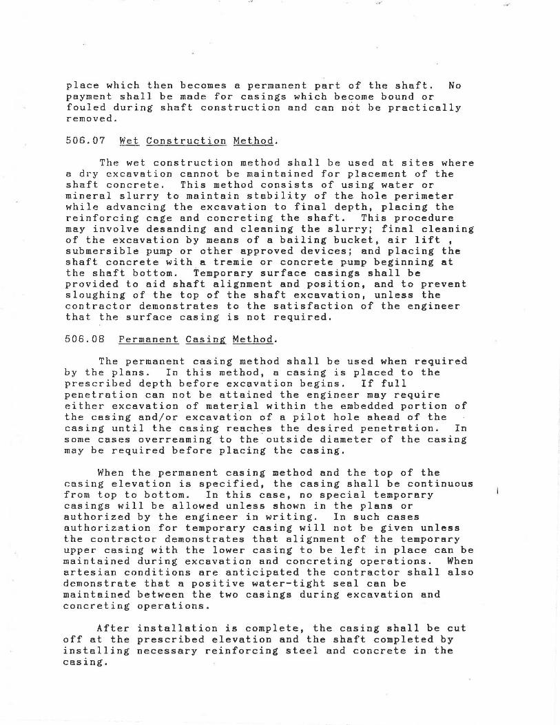
place which then becomes a permanent part of the shaft. No payment shall be made for casings which become bound or fouled during shaft construction and can n~t be practically removed.
506.07 Wet Construction Method.
The wet construction method shall be used at sites where a dry excavation cannot be maintained for placement of the shaft concrete. This method consists of using water or mineral slurry to maintain stability of the hole perimeter while advancing the excavation to final depth, placing the reinforcing cage and concreting the shaft. This procedure may involve desanding and cleaning the slurry; final cleaning of the excavation by means of a bailing bucket, air lift , submersible pump or other approved devices; and placing the shaft concrete with a tremie or concrete pump beginning at the shaft bottom. Temporary surface casings shall be provided to aid shaft alignment and position, and to prevent sloughing of the top of the shaft excavation, unless the contractor demonstrates to the satisfaction of the engineer that the surface casing is not required.
506.08 Permanent Casing Method.
The permanent casing method shall be used when required by the plans. In this method, a casing is placed to the prescribed depth before excavation begins. If full penetration can not be attained the engineer may require either excavation of material within the embedded portion of the casing and/or excavation of a pilot hole ahead of the casing until the casing reaches the desired penetration. In some cases overreaming to the outside diameter of the casing may be required before placing the casing.
When the permanent casing method and the top of the casing elevation is specified, the casing shall be continuous from top to bottom. In this case, no special temporary casings will be allowed unless shown in the plans or authorized by the engineer in writing. In such cases authorization for temporary casing will not be given unless the contractor demonstrates that alignment of the temporary upper casing with the lower casing to be left in place can be maintained during excavation and concreting operations. When artesian conditions are anticipated the contractor shall also demonstrate that a positive water-tight seal can be maintained between the two casings during excavation and concreting operations.
After installation is complete, the casing shall be cut off at the prescribed elevation and the shaft completed by installing necessary reinforcing steel and concrete in the casing.
...
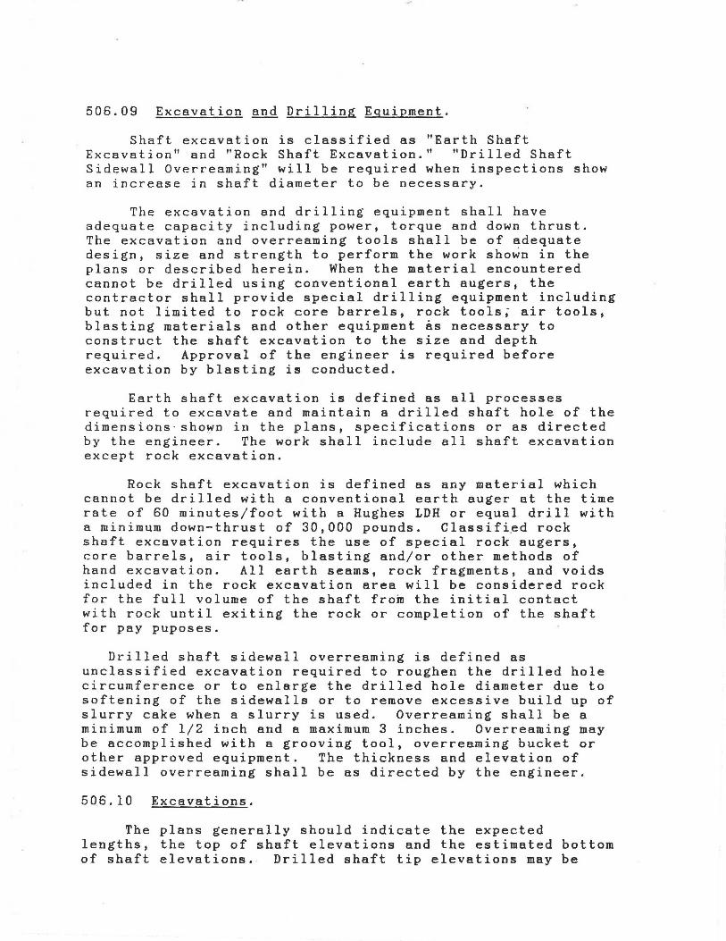
506.09 Excavation and Drilling Equipment.
Shaft excavation is classified as "Earth Shaft Excavation'' and "Rock Shaft Excavation." "Drilled Shaft Sidewall Overreaming" will be required when inspections show an increase in shaft diameter to be necessary.
The excavation and drilling equipment shall have adequate capacity including power, torque and down thrust. The excavation and overreaming tools shall be of adequate design, size and strength to perform the work shown in the plans or described herein. When the material encountered cannot be drilled using conventional earth augers, the contractor shall provide special drilling equipment including but not limited to rock core barrels, rock tools; air tools, blasting materials and other equipment as necessary to construct the shaft excavation to the size and depth required. Approval of the engineer is required before excavation by blasting is conducted.
Earth shaft excavation is defined as all processes required to excavate and maintain a drilled shaft hole of the dimensions · sho~n in the plans, specifications or as directed by the engineer. The work shall include all shaft excavation except rock excavation.
Rock shaft excavation is defined as any material which cannot be drilled with a conventional earth auger at the time rate of 60 minutes/foot with a Hughes LDH or equal drill with a minimum down-thrust of 30,000 pounds. Classifi~d rock shaft excavation requires the use of special rock augers, core barrels, air tools, blasting and/or other methods of hand excavation. All earth seams, rock fragments, and voids included in the rock excavation area will be considered rock for the full volume of the shaft from the initial contact with rock until exiting the rock or completion of the shaft for pay puposes.
Drilled shaft sidewall overreaming is defined as unclassified excavation required to roughen the drilled hole circumference or to enlarge the drilled hole diameter due to softening of the sidewalls or to remove excessive build up of slurry cake when a slurry is used. Overreaming shall be a minimum of 1/2 inch and a maximum 3 inches. Overreaming may be accomplished with a grooving tool, overreaming bucket or other approved equipment. The thickness and elevation of sidewall overreaming shall be as directed by the engineer.
506.10 Excavations.
The plans generally should indicate the expected lengths, the top of shaft elevations and the estimated bottom of shaft elevations. Drilled shaft tip elevations may be
extended during construction when the engineer determines that the material encountered during excavation is unsuitable and/or differs from that anticipated in the design of the · drilled shaft. Drilled shaft elevations may be stopped before the elevation shown on the plans if the engineer determines that the material encountered during construction is suitable to that anticipated in the design of the drilled shaft and will carry the design load.
On projects with cofferdams, the contractor shall provide a qualified diver to inspect the cofferdam conditions when a seal is required for construction. The diver shall inspect the cofferdam periphery including each sheeting indentation and around each drilled shaft to ensure no layers 6f mud or undesirable material were left above the bottom of the seal during the excavation process.
The contractor shall drill probe.holes when shown on the plans or as directed by the engineer to a maximum depth of 10 feet to determine the character of the material directly below the shaft excavation. The engineer will inspect the probe holes and determine the final depth of required excavation based on his evaluation of the materials suitability.
The contractor shall maintain a construction method log during shaft excavation and during exploration operations. The log shall contain information such as the description of and top and bottom elevation of each soil or rock material and remarks. Probe hole depths and remarks shall also be contained in the contractor's log. Two copies of the typed, final contractor's log shall be furnished to the engineer at the time the shaft excavation is completed and accepted.
506.11 Casings.
Casings shall be metal, smooth, watertight, clean and of ample strength to withstand both handling and driving stresses and the pressure of both concrete and the surrounding earth materials .. The inside diameter of casing shall not be less than the specified size of shaft. No extra compensation will be allowed for concrete required to fill an oversized casing or oversized excavation. All casings, except those used for the permanent casing method, shall be removed. When casings which are to be removed become bound in the shaft excavation and can not be practically removed and the design is based on side friction, the shaft excavation shall be drilled deeper as directed by the engineer to compensate for loss of capacity due to the presence of the casing. In this case, no compensation will be paid for casing remaining in place. The additional length of excavation shall be paid under item nos. 506.19 and 506.20.
When the shaft extends above ground or through a body of water, the portion exposed above ground or through a body of water may be formed with removable casing except when the permanent casing method is specified. For permanent casings, the portion of metal casings between an elevation 2 feet below the lowest water elevation and the top of shaft elevation shall be removed in a manner that will not damage the concrete. Special casing systems which are designed to permit removal after the concrete is hardened may be used in open water areas, when approved. Casings can be removed when the concrete has attained sufficient strength provided (a) curing or the concrete is continued for the full 72 hours period in accordance with specifications; (b) the shaft concrete is not exposed to salt water or moving water for 7 days; and (c) the concrete reaches a compressive strength of at least 2500 psi.
Temporary casings shall be removed while the concrete remains workable. Generally the removal of temporary casing shall not be started until concrete placement in the shaft is completed. Movement of the casing by rotating, exerting downward pressure and tapping to facilitate extraction or extraction with a vibratory hammer will be permitted. Casing extraction shall be at a slow, uniform rate with the pull in line with the shaft axis. Application of eccentric forces which induce undesirable moments in the shaft will not be permitted.
A sufficient head of concrete shall be maintained above the bottom of the casing to overcome the hydrostatic pressure of water outside of the casing. At all times the elevation of the concrete in the casing shall be maintained high enough to displace the drilling slurry between the outside of the casing and the wall of the excavation as the casing is removed.
506.12 Slurry.
When slurry is employed in the drilling process as described earlier, a mineral slurry shall be employed. The slurry shall have both a mineral grain size that will remain in suspension and sufficient viscosity and gel characteristics to transport excavated material to a suitable screening system. The percentage and specific gravity of the material used to make the suspension shall be sufficient to maintain the stability of the excavation and to allow proper concrete placement. During construction, the level of the slurry shall be maintained at a height sufficient to prevent caving of the hole. In the event of a sudden significant loss of slurry to the hole, the construction of that foundation shall be delayed until an alternate construction procedure has been approved.
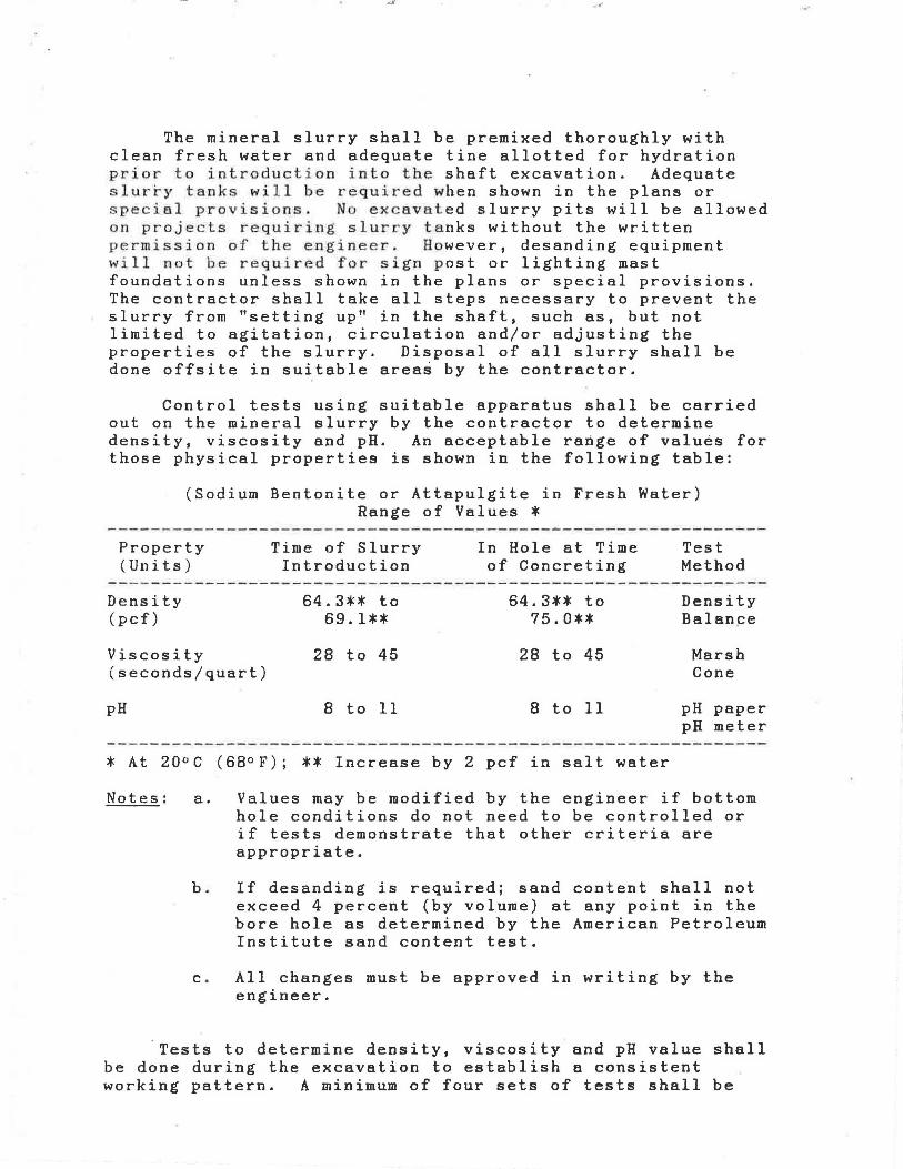
The mineral slurry shall be premixed thoroughly with clean fresh water and adequate tine allotted for hydration prior to in troduction into the shaft excavation. Adequate sl u r~y tan ks will be required when shown in the plans or special provisions. No excavat ed slurry pits will be allowed on projects requiring slurry tanks without the written permi ssion of the engineer. However, desanding equipment will not be required for sign post or lighting mast foundations unless shown in the plans or special provisions. The contractor shall take all steps necessary to prevent the slurry from "setting up'' in the shaft, such as, but not limited to agitation, circulation and/or adjusting the properties of the slurry. Disposal of all slurry shall be done offsite in suitable areas by the contractor.
Control tests using suitable apparatus shall be carried out on the mineral slurry by the contractor to determine density, viscosity and pH. An acceptable range of values for those physical properties is shown in the following table:
(Sodium Bentonite or Attapulgite in Fresh Water) Range of Values *
Property (Units)
Time of Slurry Introduction
In Hole at Time of Concreting
Test Method
Density 64.3** to 64.3** to Density (pcf) 69.1** 75.0** Balan~e
Viscosity 28 to 45 28 to 45 Marsh (seconds/quart) Cone
pH 8 to 11 8 to 11 pH paper pH meter
*At 20°C (68°F); ** Increase by 2 pcf in salt water
Notes: a. Values may be modified by the engineer if bottom hole conditions do not need to be controlled or if tests demonstrate that other criteria are appropriate.
b. If desanding is required; sand content shall not exceed 4 percent (by volume) at any point in the bore hole as determined by the American Petroleum Institute sand content test.
c. All changes must be approved in writing by the engineer.
Tests to determine density, viscosity and pH value shall be done during the excavation to establish a consistent working pattern. A minimum of four sets of tests shall be

.._..
made during the first 8 hours of slurry use. When the results show consistent behavior the testing frequency shall be decreased to one set every four hours of slurry use.
Prior to placing concrete in any shaft excavation, slurry samples shall be taken from the base of the shaft and at intervals not exceeding 10 feet up the shaft, using a sampling tool similar to that shown in figure 1. The contractor shall take whatever action is necessary to bring the mineral slurry within specification requirements.
Reports of all tests required above signed by an authorized representative of the contractor, shall be furnished to the engineer on completion of each drilled shaft.
During construction, the level of mineral slurry in the shaft excavation shall be maintained at a level not less than 4 feet above the highest expected piezometric water pressure along the depth of a shaft.
If at any time the slurry construction method fails 1n the opinion of the engineer to produce the desired final results, then the contractor shall both discontinue this method and propose an alternate method for approval.
506.13 Excavation Inspection.
The contractor shall provide equipment for checking the dimensions and alignment of each permanent shaft excavation. The dimensions and alignment shall be determined by the contractor under the direction of the engineer. Generally, the alignment and dimensions may be checked by any of the following methods as necessary:
(a) Check the dimensions and alignment of dry shaft excavations using reference stakes and a plumb bob.
(b) Check the dimensions and alignment of casing when inserted in the excavation.
(c) Insert a casing in shaft excavations temporarily for alignment and dimension checks.
(d) Insert a rigid rod assembly with several 90 degrees offsets equal to the shaft diameter into the shaft diameter into the shaft excavation for alignment and dimension checks.
The depth of the shaft during drilling shall generally be referenced to appropriate marks on the kelly bar other suitable methods. Final shaft depth shall be measured with a suitable weighted tape or other approved methods after final cleaning.
The contractor's cleaning operation will be adjusted so that a minimum of 50 percent of the base of each shaft will have less than 1/2 inch of sediment at the time of placement of the concrete. The maximum depth of sediment or any debris at any place on the base of the shaft shall not exceed l 1/2 inches. Shaft cleanliness will be determined by the engineer, by visual inspection for dry shafts or other methods deemed appropriate to the engineer for wet shafts.
Any excavation work lasting more than 36 hours (measured from the beginning of excavation for all methods except the permanent casing method where time measurement shall begin when excavation begins below the casing) before placement of the concrete may require overreaming of the sidewall to the depth of softening or to remove exces•ive slurry cake build up. The amount of overreaming shall be determined by the engineer based on samples extracted from the sidewall or other methods employed by the engineer. The contractor shall bear the cost of any overreaming required when the 36 hour limit is exceeded unless the time limit is exceeded solely to accomplish extra depth excavation ordered by the engineer. The Department will pay the contractor for sidewall cleaning during both the initial 36 hour period when sampling indicates softening or filter cake build up is occurring and after the 36 hour limit in order to accomplish extra depth excavation ordered by the engineer.
506.14 Reinforcing Steel Cage Construction and Placement.
The reinforcing steel cage consisting of longitudinal bars, ties, cage stiffener bars, spacers, centralizers and other necessary appurtenance shall be completely assembled and placed as a unit immediately after the shaft excavation is inspected and accepted prior to concrete placement.
If the bottom of the constructed shaft elevation is lower than the bottom of the shaft elevation in the plans, a minimum of one half of the longitudinal bars required in the upper portion of the shaft shall be extended the additional length. Tie bars shall be continued for the extra depth, spaced on 2 foot center, and the stiffener bars shall be extended to the final depth. These bars may be lap spliced, or unspliced bars of the proper length may be used. Welding to the planned reinforcing steel will not be permitted unless specifically shown in either the plans or special provisions.
The reinforcing steel in the shaft shall be tied and supported so that the reinforcing steel will remain within allowable tolerances given in section 506.17 of this specification. Concrete spacers or other approved noncorrosive spacing devices shall be used at sufficient intervals (near the bottom and at intervals not exceeding 5 feet up the shaft) to insure concentric spacing for the entire cage length. Spacers shall be constructed of approved
material equal in quality and durability to the concrete specified for the shaft.
The elevation of the top of the steel cage shall be checked before and after the concrete is placed. If the rebar cage is not maintained within the specified tolerancesJ correction shall be made by the contractor as directed by the engineer. No additional shafts shall be constructed until the 6ontractor has modified his rebar cage support in a manner satisfactory to the engineer.
506.15 Concrete Placement.
The work shall be performed in accordance with the applicable portions of the general specifications on concrete materials in section 506.02 of this specification and with the requirements herein.
Concrete shall be placed as soon as possible immediately after reinforcing steel placement. Concrete placement shall be continuous in the shaft to the top elevation of the shaft. Concrete placement shall continue after the shaft is full until good quality concrete is evident at the top of the shaft. Concrete shall be placed through a tremie, concrete pump or centering hopper using approved methods as described in section 506.16.
The elapsed time from the beginning of concrete placement in the shaft to the completion of the placement shall not exceed 2 hours. Retarding plasticizer in the concrete mix shall be adjusted as approved for the conditions encountered on the job so that concrete remains in a workable plastic state throughout the 2 hour placement limit.
When the top of shaft elevation is above ground, the portion of the shaft above ground shall be formed with a removable form or another approved method to the dimensions shown on the plans. When the shaft extends above the ground through a body of water, the portion through the water may be formed with removable forms except when the driven casing method is specified. When approved the portion through the water may be formed with permanent forms provided the forms from 2 feet below the lowest water elevation to the top of shaft elevation are removed.
Portions of drilled shafts exposed to a body of water shall be protected from the action of water by leaving the forms in place for a minimum of 7 days after casting the concrete. Forms may be removed prior to 7 days provided the concrete strength has reached 2500 psi or greater as evidenced by cylinder breaks.
The excavation shall be dewatered prior to the placement of concrete. Pumping shall be performed in a manner that

will not create ground loss problems that might adversely affect this and existing adjacent structures as determined by the engineer. If during pumping excessive water inflow is noted, use alternative means to reduce inflow such as extending casing, grouting, or other acceptable means. If water seepage is still excessi v e as determined by the geotechnical engineer, then the tremie method should be used. If a water problem exists, the drilling contractor shall be permitted, at his option, to go directly to the underwater concrete placement method.
If the hole is dewatered as described above and permission from the inspector is granted, the concrete may then be placed by free fall using a hopper, or equivalent, to ensure the fall is vertical and the concrete does not hit the sides or reinforcing. Only the top 5 feet of concrete needs to be vibrated after construction is complete.
The underwater concrete placement method is accomplished by using a tremie. Tremies used to place concrete shall consist of a tube of sufficient length to meet the requirements below. The tremie shall not contain aluminum parts which will have contact with the concrete. The contractor may only use concrete pumps in lieu of tremies for concrete placement when approved by the engineer. All pump lines shall have a minimum 4 inch diameter and shall be constructed with watertight joints.
The tremie used for wet excavation concrete placement shall be watertight. The discharge end of the tremie shall be constructed to permit the free flow of concrete during placement operations. The length and weight of tremie shall be sufficient to extend to the bottom of the excavation. The discharge end shall be entirely immersed in concrete at all times after starting the flow of concrete. The flow of the concrete shall be continuous and the concrete in the tremie shall be maintained at a positive pressure differential at all times to prevent water or slurry intrusion into the shaft concrete.
506.16 Test Holes.
When a pay item for test shaft holes is included in the contract, the engineer may ·require one or more test shaft holes to be constructed. The construction test shaft holes will be used to determine if the methods, equipment and procedures used by the contractor are sufficient to produce a shaft excavation which meets the requirements of the plans and specifications. Site specific requirements may include: to control dimensions and alignment of excavations within tolerances; to seal the casing into impervious materials; to control the size of the excavation under ·caving conditions by the use of a mineral slurry or by other means; to properly clean the completed shaft excavation; to construct

.... ...
excavations in open water areas; to determine the elevation of groundwater; and to satisfactorily execute any other necessary construction operation.
The contractor shall revise his methods and equipment as necessary at any time during the construction of the test shaft hole to satisfactorily carry out any necessary operation described "above or to control the dimensions and alignment of the shaft excavation within specified tolerances.
Test shaft holes shall be located at least three shaft diameters from the permanent shaft location, shown on the plans, or as directed by the engineer. The diameter and depth of the test shaft hole or holes shall be the same diameter and depth of the production drilled shafts as shown on the plans or as otherwise directed by the engineer. The test shaft holes will generally be filled with unreinforced concrete in the same manner that production shafts will be constructed. In some cases, when shown on the plans or directed by engineer, the test shaft holes may be backfilled with suitable soil in a manner satisfactory to the engineer. The concreted test shafts shall be cutoff 2 feet below finished grade and left in place. The disturbed areas at the sites of the test shaft holes shall be restored as practical to their original condition. When the contractor fails to satisfactorily demonstrate the adequacy of his methods, procedures, equipment and/or alternatives required, additional test shaft holes shall be provided at no cost to the Department.
506.17 Construction Tolerances.
The following construction tolerances apply to drilled shafts:
1. The drilled shaft shall be within one twelveth of the shaft diameter or 3 inches, whichever is less, of plan position in the horizontal plane at the plan elevation for the top of the shaft.
2. The vertical alignment of the shaft excavation shall not vary from the plan alignment by more than 1/4 inch per foot of depth .
. 3. After all the concrete is placed, the top of the reinforcing steel cage shall be no more than 6 inches above and no more than 3 inches below plan position.
4. All casing diameters shown on the plans refer to O.D. (outside diameter) dimensions. When approved the contractor may elect to provide a casing larger in diameter than shown in the plans to facilitate meeting this requirement. When casing is not used, the minimum
diameter of the drilled shaft shall be 1 inch less than the specified shaft diameter. When conditions are such that a series of telescoping casings are used, the casing shall be sized so that the minimum shaft diameters listed above can be maintained.
5. The top elevation of the shaft shall have a tolerance of plus or minus 1 inch from the plan top of shaft elevation.
6. The dimensions of casings are subject to American Pipe Institute tolerances applicable to regular steel pipe.
7 . Excavation equipment and methods shall be designed so that the completed shaft excavation will have a flat bottom. The cutting edges of excavation equipment shall be normal to the vertical axis of the equipment within a tolerance of ± 3/8 inch per foot of diameter.
Drilled shaft excavations constructed in such a manner that the concrete shaft can not be completed within the required tolerances are unacceptable. When approved, corrections may be made to an unacceptable drilled shaft excavation by any approved combination of the following methods:
1. Overdrill the shaft excavation to a larger diameter to permit accurate placement of the reinforcing steel cage with the required minimum concrete cover.
2. Increase the number and/or size of the steel reinforcement bars.
The approval of correction procedures is dependent on analysis of the effect of the degree of misalignment and improper positioning. Correction methods may be approved as design analysis indicate. Redesign drawings and computations prepared by the contractor's engineer shall be signed by a licensed professional engineer. Materials and work necessary, including engineering analysis and redesign, to effect corrections for out of tolerance drilled shaft excavations shall be furnished at no cost to the Department.
506.18 Drilled Shaft Load Tests.
When contract documents include load testing, all tests shall be completed before construction of any production drilled shafts. The contractor shall allow 4 weeks after the last load test for the analysis of the load test data by the engineer before estimated drilled shaft tip elevations will be provided for production shafts.
.·
The contractor shall obtain the services of a licensed professional engineer, with satisfactory load test experience, to conduct the test in compliance with these specifications, record all data and furnish reports of the test results to the engineer, The use of load tests, the number of load tests and locations shall be as shown on the plans or as designated by the engineer. Loads for the tests shall be the maximum shown on the plarls or a lesser load that the shaft will support. ·
Static load testing shall not begin until the concrete has attained a compressive strength of 3400 psi. Drilled shafts shall be load tested in the order directed by the engineer. Static load tests shall be completed as described in ASTM Dll43 (compression test) and ASTM D3966 (lateral test) or as modified herein. The contractor shall supply all equipment necessary to conduct the static test. The loading frame apparatus shall be designed to accommodate the maximum load plus an adequate safety factor.
The contractor shall notify the engineer within 10 days of contract award of the load testing schedule.
Load cells will be required for drilled shaft load tests. Load cells shall be of adequate size to measure the maximum load to the applied shaft and shall be equipped with an adequate readout device. Before load testing begins, the contractor shall furnish a certificate from an approved testing laboratory, of calibration for the load cell within the preceeding 6 months for all stages of loading and unloading. The accuracy of the load cell shall be within 1 percent of the true load.
After testing is completed, the test shafts (and any reaction shafts) shall be cut off at an elevation 2 feet below the finished ground surface, The portion of the shafts cut off and removed shall remain the property of the contractor.
506.19 Method of Measurement.
(a) Overhead: The quantity to be paid includes move-in, move-out and supervision.
(b) Earth Shaft Excavation: The quantities to be paid shall be the length. in feet from the top elevation of each shaft sho~n on the plans, to completion or to the point from which the auger is withdrawn due to encountering material too hard to be removed by the earth auger. If the hard material is removed and the auger can be placed back into the hole, earth augering will resume.
~c) Rock Shaft Excavation: The quantities to be paid shall be the length in feet of material that cannot be removed

at the time rate of 60 minutes/foot with a Hughes LDH or equal drill with a minimum down-thrust of 30,000 pounds.
(d) Concrete: The quantity to be paid is measured as the number of cubic yards of concrete poured in shaft excavations as shown by delivery ticket numbers and quantities placed in each shaft.
(e) Reinforcing: Reinforcing is measured in pounds placed in the shaft excavatioris.
(f) Drilled Shaft Sidewall Overreaming: The quantities to be paid shall be the length in feet of drilled shaft sidewall overreaming authorized, completed and accepted, measured between the elevation limits shown on the plans or authorized by the engineer.
(g) Test Shaft: The quantity of test shaft holes shall be the authorized linear feet of test shaft holes drilled of the diameter shown on the plans, completed (including backfill when required) and accepted. The linear feet of test shaft holes shall be determined as the difference between the existing ground surface elevation at the center of the test shaft hole prior to drilling and the authorized bottom elevation of the hole.
(h) Exploration (Shaft Excavation): The quantity to be paid for under this item shall be the length in linear feet, measured from the bottom of shaft elevation to the bottom of the exploration hole, for each authorized
_probe hole drilled below the shaft .excavation.
(i) Load Tests: The quantity to be paid for under this item shall be the number of load tests conducted according to the loading procedures described and of the designated load shown in the plans or authorized, applied and accepted.
(j) Permanent Casings: The quantity to be paid for under this item shall be the linear feet of each size casing as directed and authorized to be used. The length to be paid for shall be measured along the casing from the top of the shaft elevation or the top of casing whichever is lower to the bottom of the casing at each shaft location where casing is authorized and used.
When a top of casing is shown in the plans, payment shall be from the plan elevation or to the actual top of casing elevation, whichever is lower, to the bottom of the casing. When the contra ctor elects to use an approved special temporary casing system in open water locations, the length to be paid shall be measured as a single casing as provided above.
(k) Instrumentation and Data Collection: The quantity to be paid for shall be lump sum for payment of all specified instrumentation, all cost associated with collection of data, all required analyses and any required reports.
(1) Protection of Existing Structures: The quantity to be paid for of this item, when included in the plans, shall be lump sum. When the plans do not include an item for protection of existing structured and the engineer orders work to be performed for protection of existing structures, this work shall be paid for as extra work.
506.20 Basis of Payment.
(a) Overhead: Overhead including move-in, move-out and supervision shall be paid as a lump sum.
(b) Earth Shaft Excavation: Earth shaft excavation shall be paid for at the contract unit price per linear foot for drilled shafts of the diameter specified. Such price and payment shall be full compensation for the shaft excavation (except for the additional costs included under the associated pay items for rock shaft excavation and permanent casing), removal from the site and disposal of excavated materials, using slurry as necessary, using special tools and drilling equipment to excavate the shaft to the depth indicated on the plans, and furnishing all other labor, materials and equipment necessary to complete the work in an acceptable manner.
(c) Rock Shaft Excavation: Rock shaft excavation shall be paid for at the contract unit price per linear foot for drilled shafts of the diameter specified. Such price and payment shall be full compensation for the rock shaft excavation (except for the additional costs included under the associated pay items for permanent casing), removal from the site and disposal of excavated materials, using drilling equipment, blasting procedures and special tools to excavate the shaft to the depth indicated on the plans, and furnishing all other labor, materials and equipment necessary to complete the work in an acceptable manner.
(d) Concrete: Concrete shall be paid for at the contract price per cubic yard.
( e ) Reinforcing: Reinforcing including dowels shall be paid for at the contract price per pound.
(f) Drilled Shaft Sidewall Overreaming: Drilled shaft sidewall overreaming shall be paid for at the contract unit price per number of feet of sidewall overreaming authorized, completed and accepted. Such price and payment shall be full compensation for all labor,
..
equipment and incidentals necessary to accomplish acceptable construction.
(g) Test Shaft Holes: Test shaft holes of the specified diameter will be paid for at the contract unit price per linear foot for test shaft holes. Such price and payment shall be full compensation for excavating the test shaft hole through whatever materials are encountered to the bottom of shaft elevation shown on the plans or as authorized by the engineer, providing inspection facilities, backfilling the hole, restoring the site as required and all other expenses to complete the work.
(h) Exploration (Shaft Excavation): Probe holes of the length required and authorized by the engineer will be paid for at the contract unit price per linear foot of probe hole. Such price and payment shall be full compensation for drilling , furnishing Class III or Class IV Concrete to fill the probe hole and other expenses necessary to complete the work.
(i) Load Tests: Load tests shall be paid for at the contract unit each, for load tests, completed and accepted. Such price and payment shall include all cost related to the performance of the load test.
(j) Permanent Casing: Permanent casings shall be paid for at the contract price per linear foot. Such price and payment shall be full compensation for additional costs necessary for furnishing, and placing the casing in the shaft excavation above the costs attributable to the work paid for under associated pay items for earth shaft excavation and rock shaft excavation.
(k) Instrumentation and Data Collection: The contractor shall include in his bid the cost to pay for the instrumentation and data collection and when required the load test report.
(1) Protection of Existing Structures: The quantity of this item, shall be paid for at the contract unit price, lump sum, for protection of existing structures.
(m) Items of Payment: Payment shall be made under:
Overhead - lump sum. Earth Shaft Excavation - per linear foot. Rock Shaft Excavation - per linear foot. Concrete - per cubic yard. Reinforcing - per pound. Drilled Shaft Sidewall Overreaming - per linear foot. Test shaft - per linear foot. Exploration (Probe Hole) - per linear foot.
Load Test - each. Permanent Casing - per linear foot. Instrumentation and Data Collection - lump sum. Protection of Existing Structures - lump sum.

Appendix c. Bid Documents
Typical pay items and costs for drilled shaft foundations:
A. Overhead (including move-in, move-out and etc.): Lump Sum $ 50.000.00
B. Installation of Rock Bearing Shafts:
1. Earth Excavation (including excavation, casing, shoring and pumping):
Linear Unit Diameter Feet Price
30 in. @ $ 20.00/l.f. = $ 36 in. @ $ 26.00/l.f. = $ 42 in. @ $ 35.00/l.f. = $ 48 in. @ $ 40.00/l.f. = $ 54 in. @ $ 44.00/l.f. = $ 60 in. . @ $ 50.00/l.f • = $ 66 in. @ $ 56.00/l.f. = $ 72 in. @ $ 63.00/l.f. = $
2. Rock Excavation (including excavation, casing shoring and pumping) :
Linear Unit Diameter Feet Price
30 in. @ $ 200.00/l.f. = $ 36 in. @ $ 235.00/l.f. = $ 42 in. @ $ 280.00/l.f. = $ 48 in. @ $ 350.00/l.f~ = $ 54 in. @ $ 375.00/l.f. = $ 60 in. @ $ 410.00/l.f. = $ 66 in. @ $ 460.00/l.f. = $ 72 in. @ $ 530.00/l.f. = $
3. Shaft Concrete (per dray ticket) :
c.y. @ $ 55.00/c.y. = $ ___ _ _
4. Reinforcing Steel:
lbs. @ $ 0.45/lbs. = $ ____ _
5. Test Holes:
ft. @ $ 18.00/ft. = $ ___ _
TOTAL DRILLED SHAFT FOUNDATION COST •......••.•....... $ ________ _

Appendix D. Cost Comparison [I-565-5(22)]
COST OF CONCRETE PILE CAPS [I-565-5(22)]
TYPE * YARDS POUNDS COST FOOTING PILES CONCRETE REBAR ( $ )
$160 yd $.38 1b
F-IV 4 10.69 934 $2,065 F-V 5 10.69 934 $2,065 F-VI 6 14.97 1397 $2,926 F-VIA 6 17.42 1555 $3,378 F-VIII 8 17.42 1693 $3,431 F-VIIIA 8 22.44 2531 $4,552 F-IX 9 17.42 1693 $3,431 F-IXA 9 47.36 3580 $8,938 F-X 10 21.08 2210 $4,213 F-XA 10 27.08 2425 $5,254 F-XII 12 27.08 2529 $5,294 F-XIV 14 36.11 3469 $7,096 F-SIX 9 41.41 3500 $7,956 F-SX 10 64.70 6837 $12,950 F-SXI 11 64.70 6837 $12,950 F-SXII 12 80.23 6496 $15,305 F-SXIII 13 82.75 8923 $16,631 F-SXV 15 102.62 10276 $20,324 F-SXVA 15 64.70 6837 $12,950 F-SXVI 16 95.75 9467 $18,917 F-SXVIII 18 78.24 7915 $15,526 F-SXX 20 142.34 13878 $28,048
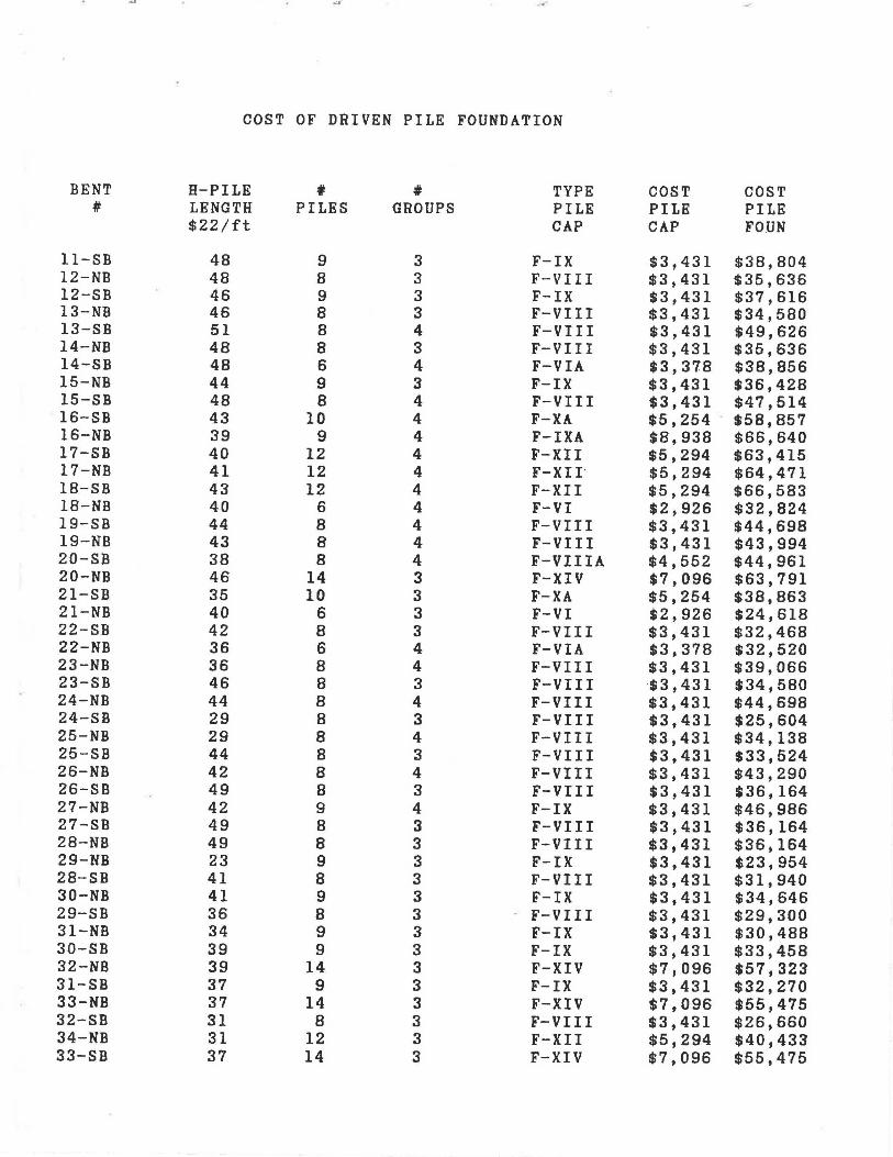
COST OF DRIVEN PILE FOUNDATION
BENT H-PILE ' ' TYPE COST COST # LENGTH PILES GROUPS PILE PILE PILE
$22/ft CAP CAP FOUN
11-SB 48 9 3 F-IX $3,431 $38,804 12-NB 48 8 3 F-VIII $3,431 $35,636 12-SB 46 9 3 F-IX $3,431 $37,616 13-NB 46 8 3 F-VIII $3,431 $34,580 13-SB 51 8 4 F-VIII $3,431 $49,626 14-NB 48 8 3 F-VIII $3,431 $35,636 14-SB 48 6 4 F-VIA $3,378 $38,856 15-NB 44 9 3 F-IX $3,431 $36,428 15-SB 48 8 4 F-VIII $3,431 $47,514 16-SB 43 10 4 F-XA $5,254 . $58,857 16-NB 39 9 4 F-IXA $8,938 $66,640 17-SB 40 12 4 F-XII $5,294 $63,415 17-NB 41 12 4 F-XII· $5,294 $64,471 18-SB 43 12 4 F-XII $5,294 $66,583 18-NB 40 6 4 F-VI $2,926 $32,824 19-SB 44 8 4 F-VIII $3,431 $44,698 19-NB 43 8 4 F-VIII $3,431 $43,994 20-SB 38 8 4 F-VIIIA $4,552 $44,961 20-NB 46 14 3 F-XIV $7,096 $63,791 21-SB 35 10 3 F-XA $5,254 $38,863 21-NB 40 6 3 F-VI $2,926 $24,618 22-SB 42 8 3 F-VIII $3,431 $32,468 22-NB 36 6 4 F-VIA $3,378 $32,520 23-NB 36 8 4 F-VIII $3,431 $39,066 23-SB 46 8 3 F-VIII $3,431 $34,580 24-NB 44 8 4 F-VIII $3,431 $44,698 24-SB 29 8 3 F-VIII $3,431 $25,604 25-NB 29 8 4 F-VIII $3,431 $34,138 25-SB 44 8 3 F-VIII $3,431 $33,524 26-NB 42 8 4 F-VIII $3,431 $43,290 26-SB 49 8 3 F-VIII $3,431 $36,164 27-NB 42 9 4 F-IX $3,431 $46,986 27-SB 49 8 3 F-VIII $3,431 $36,164 28-NB 49 8 3 F-VIII $3,431 $36,164 29-NB 23 9 3 F-IX $3,431 $23,954 28-SB 41 8 3 F-VIII $3,431 $31,940 30-NB 41 9 3 F-IX $3,431 $34,646 29-SB 36 8 3 F-VIII $3,431 $29,300 31-NB 34 9 3 F-IX $3,431 $30,488 30-SB 39 9 3 F-IX $3,431 $33,458 32-NB 39 14 3 F-XIV $7,096 $57,323 31-SB 37 9 3 F-IX $3,431 $32,270 33-NB 37 14 3 F-XIV $7,096 $55,475 32-SB 31 8 3 F-VIII $3,431 $26,660 34-NB 31 12 3 F-XII $5,294 $40,433 33-SB 37 14 3 F-XIV $7,096 $55,475

35-NB' 34 14 3 F-XIV $7,096 $52,703 34-SB 19 12 3 F-XII $5,294 $30,929 36-NB 19 14 3 F-XIV $7,096 $38,843 35-SB 11 14 3 F-XIV $7,096 $31,451 37-NB 11 14 3 F-XIV $7,096 $31,451 36-SB 24 8 3 F-VI II $3,431 $22,964 38-NB 24 12 3 F-XII $5,294 $34,889 37-SB 24 8 3 F-VIII $3,431 $22,964 39-NB 24 14 3 F-XIV $7,096 $43,463 38-SB 23 9 3 F-IX $3,431 $23,954 40-NB 23 14 3 F-XIV $7,096 $42,539 39-SB 25 9 3 F-IX $3,431 $25,142 41-NB 24 14 3 F-XIV $7,096 $43,463 40-SB 30 8 3 F-VIII $3,431 $26,132 42-NB 30 8 3 F-VIIIA $4,552 $29,497 41-SB 30 8 3 F-VIII $3,431 $26,132
TOTAL COST .... $2,421,714

COST DRILLED SHAFT FOUNDATION (LIMESTONE - END BEARING = lOOks f)
DRILLED BENT SHAFT PILE VOLUME # *COST
# LENGTH DIAM EXCAVATION SHAFTS SHAFT PILE+ 7ft (ft) (cyd) FOUN
11-SB 55 4.0 25.60 3 $22,469 12-NB 55 4.0 25.60 3 $22,469 12-SB 53 4.0 24.67 3 $21,905 13-NB 53 4.0 24.67 3 $21,905 13-SB 58 4.0 26.99 4 $31,088 14-NB 55 4.0 25.60 3 $22,469 14-SB 55 3.5 19.60 4 $23,673 15-NB 51 4.0 23.74 3 $21,340 15-SB 55 4.0 25.60 4 $29,959 16-SB 50 4.5 29.45 4 $27,757 16-NB 46 4.0 21.41 4 $26,571 17-SB 47 5.0 34.18 4 $35,949 17-NB 48 5.0 34.91 4 $36,488 18-SB 50 5.0 36.36 4 $37,564 18-NB 47 3.5 16.75 4 $21,324 19-SB 51 4.0 23.74 4 $28,453 19-NB 50 4.0 23.27 4 $28,077 20-SB 45 4.0 20.94 4 $26,195 20-NB 53 5.0 38.54 3 $29,384 21-SB 42 4.5 24.74 3 $21,043 21-NB 47 3.5 16.75 3 $15,993 22-SB 49 4.0 22.81 3 $20,775 22-NB 43 3.5 15.32 4 $20,149 23-NB 43 4.0 20.01 4 $25,442 23-SB 53 4.0 24.67 3 $21,905 24-NB 51 4.0 23.74 4 $28,453 24-SB 36 4.0 16.76 3 $17,105 25-NB 36 4.0 16.76 4 $22,807 25-SB 51 4.0 23.74 3 $21,340 26-NB 49 4.0 22.81 4 $27,701 26-SB 56 4.0 26.06 3 $22,752 27-NB 49 4.0 22.81 4 $27,701 27-SB 56 4.0 26.06 3 $22,752 28-NB 56 4.0 26.06 3 $22,752 29-NB 30 4.0 13.96 3 $15,411 28-SB 48 4.0 22.34 3 $20,493 30-NB 48 4.0 22.34 3 $20,493 29-SB 43 4.0 20.01 3 $19,082 31-NB 41 4.0 19.08 3 $18,517 30-SB 46 4.0 21.41 3 $19,929 32-NB 46 5.0 33.45 3 $26,558 31-SB 44 4.0 20.48 3 $19,364 33-NB 44 5.0 32.00 3 $25,751 32-SB 38 4.0 17.69 3 $17,670 34-NB 38 5.0 27.63 3 $23,330 33-SB 44 5.0 32.00 3 $25,751
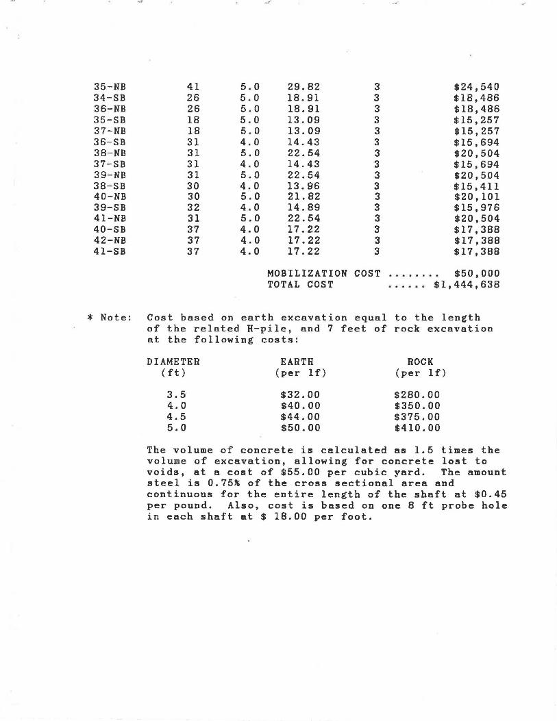
,..,. .....
35-NB 41 5.0 29.82 3 $24,540 34-SB 26 5.0 18.91 3 $18,486 36-NB 26 5 . 0 18.91 3 $18,486 35-SB 18 5.0 13.09 3 $15,257 37-NB 18 5.0 13.09 3 $15,257 36-SB 31 4.0 14.43 3 $15,694 38-NB 31 5.0 22.54 3 $20,504 37-SB 31 4 . 0 14.43 3 $15,694 39-NB 31 5.0 22.54 3 $20,504 38-SB 30 4.0 13.96 3 $15,411 40-NB 30 5.0 21.82 3 $20,101 39-SB 32 4.0 14.89 3 $15,976 41-NB 31 5.0 22.54 3 $20,504 40-SB 37 4.0 17.22 3 $17,388 42-NB 37 4.0 17.22 3 $17,388 41-SB 37 4.0 17.22 3 $17,388
MOBILIZATION COST ........ $50,000 TOTAL COST ..... . $1,444,638
* Note: Cost based on earth excavation equal to the length of the related H-pile, and 7 feet of rock excavation at the following costs:
DIAMETER (ft)
3.5 4.0 4.5 5.0
EARTH (per lf)
$32.00 $40.00 $44.00 $50.00
ROCK (per lf)
$280.00 $350.00 $375.00 $410.00
The volume of concrete is calculated as 1.5 times the volume of excavation, allowing for concrete lost to voids, at a cost of $55.00 per cubic yard. The amount steel is 0.75% of the cross sectional area and continuous for the entire length of the shaft at $0.45 per pound. Also, cost is based on one 8 ft probe hole in each shaft at $ 18.00 per foot.
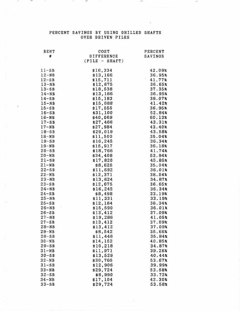
"'. •.
PERCENT SAVINGS BY USING DRILLED SHAFTS OVER DRIVEN PILES
BENT COST PERCENT , DIFFERENCE SAVINGS (PILE - SHAFT)
11-SB $16,334 42.09% 12-NB $13,166 36.95% 12-SB $15,711 41. 77% 13-NB $12,675 36.65% 13-SB $18,538 37.35% 14-NB ·$13' 166 36.95% 14-SB $15,183 39.07% 15-NB $15,088 41.42% 15-SB $17,555 36.95% 16-SB $31,100 52.84% 16-NB $40,069 60.13% 17-SB $27,466 43.31% 17-NB $27,984 43.40% 18-SB $29,019 43.58% 18-NB $11,500 35.04% 19-SB $16,245 36.34% 19-NB $15,917 36.18% 20-SB $18,766 41.74% 20-NB $34,408 53.94% 21-SB $17,820 45.85% 21-NB $8,625 35.04% 22-SB $11,692 36.01% 22-NB $12,371 38.04% 23-NB $13,624 34.87% 23-SB $12,675 36.65% 24-NB $16,245 36.34% 24-SB $8,498 33.19% 25-NB $11,331 33.19% 25-SB $12,184 36.34% 26-NB $15,590 36.01% 26-SB $13.,412 37.09% 27-NB $19,286 41.05% 27-SB $13,412 37.09% 28-NB $13,412 37.09% 29-NB $8,542 35.66% 28-SB $11,446 35.84% 30-NB $14,152 40.85% 29-SB $10,218 34.87% 31-NB $11,971 39.26% 30-SB $13,529 40.44% 32-NB $30,765 53.67% 31-SB $12,906 39.99% 33-NB $29,724 53.58% 32-SB $8,990 33.72% 34-NB $17,104 42.30% 33-SB $29,724 53.58%
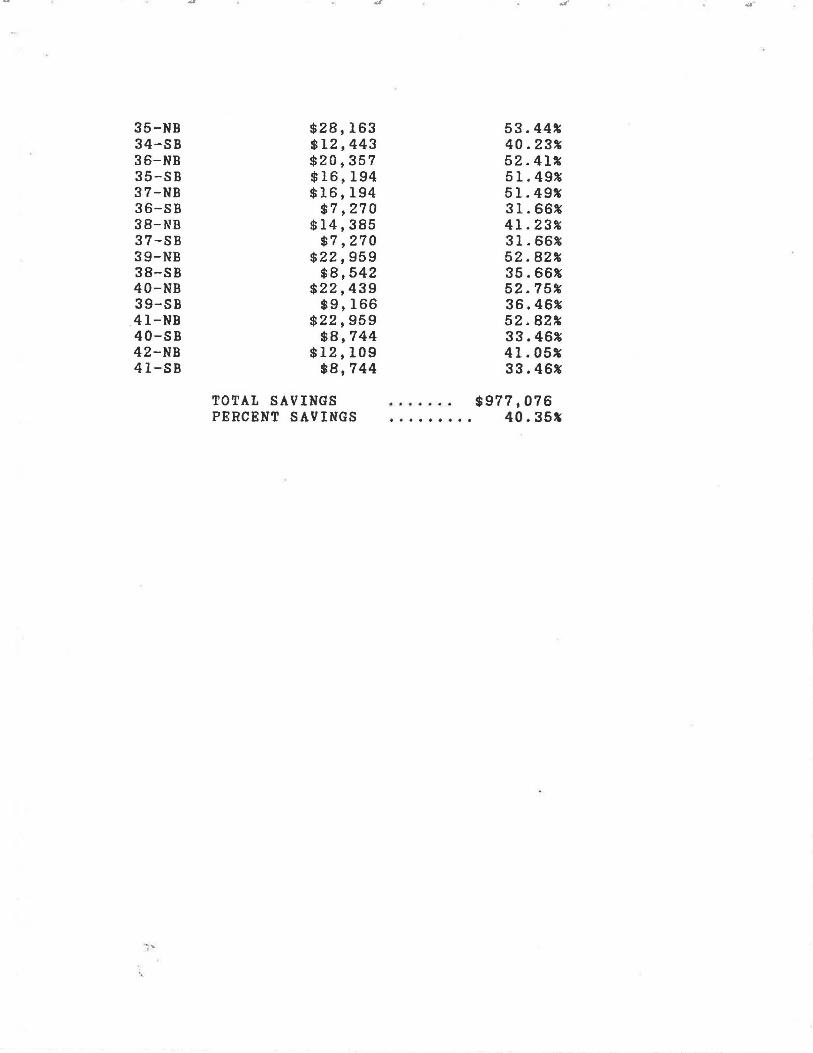
35-NB 34-SB 36-NB 35-SB 37-NB 36-SB 38-NB 37-SB 39-NB 38-SB 40-NB 39-SB 41-NB 40-SB 42-NB 41-SB
·-
$28,163 $12,443 $20,357 $16,194 $16,194
$7,270 $14,385
$7,270 $22,959
$8,542 $22,439
$9,166 $22,959
$8,744 $12,109
$8,744
TOTAL SAVINGS PERCENT SAVINGS
53.44% 40.23% 52.41% 51.49% 51.49% 31.66% 41.23% 31.66% 52.82% 35.66% 52.75% 36.46% 52.82% 33.46% 41.05% 33.46%
$977,076 40.35~
.:1"

,.,. ..
COST DRILLED SHAFT FOUNDATION (LIMESTONE - END BEARING = 60 ksf)
DRILLED BENT SHAFT PILE VOLUME # *COST
# LENGTH DIAM EXCAVATION SHAFTS SHAFT PILE+ 7ft (ft) (cyd) FOUN
11-SB 55 5.5 48.40 3 $35,034 12-NB 55 5.0 40.00 3 $30,191 12-SB 53 5.5 46.64 3 $34,085 13-NB 53 5.0 38.54 3 $29,384 13-SB 58 5.0 42.18 4 $41,869 14-NB 55 5.0 40.00 3 $30,191 14-SB 55 4.5 32.40 4 $34,589 15-NB 51 . 5. 5 44.88 3 $33,135 15-SB 55 5.0 40.00 4 · $40,255 16-SB 50 5.5 44.00 4 $43,547 16-NB 46 5.5 40.48 4 $41,014 17-SB 47 6.0 49.22 4 $48,383 17-NB 48 6.0 50.27 4 $49,122 18-SB 50 6.0 52.36 4 $50,599 18-NB 47 4.5 27.69 4 $30,990 19-SB 51 5.0 37.09 4 $38,102 19-NB 50 5.0 36.36 4 $37,564 20-SB 45 5.0 32.73 4 $34,873 20-NB 53 6.0 55.50 3 $39,612 21-SB 42 5.5 36.96 3 $28,861 21-NB 47 4.5 27.69 3 $23,242 22-SB 49 5.0 35.63 3 $27,769 22-NB 43 4.5 25.33 4 $29,190 23-NB 43 5.0 31.27 4 $33,797 23-SB 53 5.0 38.54 3 $29,384 24-NB 51 5.0 37.09 4 $38,102 24-SB 36 5.0 26.18 3 $22,522 25-NB 36 5.0 26.18 4 $30,030 25-SB 51 5.0 37.09 3 $28,577 26-NB 49 5.0 35.63 4 $37,026 26-SB 56 5.0 40.72 3 $30,595 27-NB 49 5.5 43.12 4 $42,913 27-SB 56 5.0 40.72 3 $30,595 28-NB 56 5.0 40.72 3 $30,595 29-NB 30 5.5 26.40 3 $23,162 28-SB 48 5.0 34.91 3 $27,366 30-NB 48 5.5 42.24 3 $31,710 29-SB 43 5.0 31.27 3 $25,348 31-NB 41 5.5 36.08 3 $28,386 30-SB 46 5.5 40.48 3 $30,760 32-NB 46 6.0 48.17 3 $35,733 31-SB 44 5.5 38.72 3 $29,811 33-NB 44 6.0 46.08 3 $34,624 32-SB 38 5.0 27.63 3 $23,330 34-NB 38 6.0 39.79 3 $31,299 33-SB 44 6.0 46.08 3 $34,624

35-NB 41 6.0 42.94 3 $32,962 34-SB 26 6.0 27.23 3 $24,648 36-NB 26 6.0 27.23 3 $24,648 35-SB 18 6.0 18.85 3 $20,215 37-NB 18 6.0 18.85 3 $20,215 36-SB 31 5.0 22.54 3 $20,504 38-NB 31 6.0 32.46 3 $27,420 37-SB 31 5.0 22.54 3 $20,504 39-NB 31 6.0 32.46 3 $27,420 38-SB 30 5.5 26.40 3 $23,162 40-NB 30 6.0 31.42 3 $26,865 39-SB 32 5.5 28.16 3 $24,112 41-NB 31 6.0 32.46 3 $27,420 40-SB 37 5.0 26.91 3 $22,926 42-NB 37 5.0 26.91 3 $22,926 41-SB 37 5.0 26.91 3 $22,926
MOBILIZATION COST ........ $50,000 TOTAL COST ...... $1,980,760
* Note: Cost based on earth excavation equal to the length of the related H-pile, and 7 feet of rock excavation at the following costs:
DIAMETER ( ft)
3.5 4.0 4.5 5.0 5.5 6.0
EARTH (per lf)
$32.00 $40.00 $44.00 $50.00 $56.00 $63.00
ROCK (per lf)
$280.00 $350.00 $375.00 $410.00 $460.00 $530.00
The volume of concrete is calculated as 1.5 times the volume of excavation, allowing for concrete lost to voids, at a cost of $55.00 per cubic yard. The amount steel is 0.75% of the cross sectional area and continuous for the entire length of the shaft at $0.45 per pound. Assume an 8 ft probe hole in each shaft at $18.00 per ft.
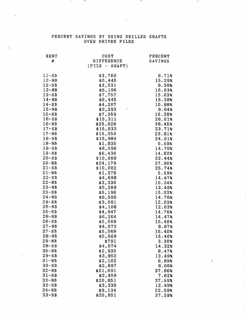
.... . ..
PERCENT SAVINGS BY USING DRILLED SHAFTS OVER DRIVEN PILES
BENT COST PERCENT # DIFFERENCE SAVINGS
(PILE - SHAFT)
11-SB $3,769 9.71% 12-NB $5,445 15.28% 12-SB $3,531 ·g. 39% 13-NB $5,196 15.03% 13-SB $7,757 15.63% 14-NB $5,445 15.28% 14-SB $4,267 10.98% 15-NB $3,293 9.04% 15-SB $7,259 15.28% 16-SB $15,311 26.01% 16-NB $25,626 38.45% 17-SB $15,033 23.71% 17-NB $15,350 23.81% · 18-SB $15,984 24.01% 18-NB $1,835 5.59% 19-SB $6,596 14.76% 19-NB $6,430 14.62% 20-SB $10,088 22.44% 20-NB $24,179 37.90% 21-SB $10,002 25.74% 21-NB $1,376 5.59% 22-SB $4,698 14.47% 22-NB $3,330 10.24% 23-NB $5,269 13.49% 23-SB $5,196 15.03% 24-NB $6,596 14.76% 24-SB $3,081 12.03% 25-NB $4,108 12.03% 25-SB $4,947 14.76% 26-NB $6,264 14.47% 26-SB $5,569 15.40% 27-NB $4,073 8.67% 27-SB $5,569 15.40% 28-NB $5,569 15.40% 29-NB $791 3.30% 28-SB $4,574 14.32% 30-NB $2,935 8.47% 29-SB $3,952 13.49% 31-NB $2,102 6.89% 30-SB $2,697 8.06% 32-NB $21,591 37.66% 31-SB $2,459 7.62% 33-NB $20,851 37.59% 32-SB $3,330 12.49% 34-NB $9,134 22.59% 33-SB $20,851 37.59%
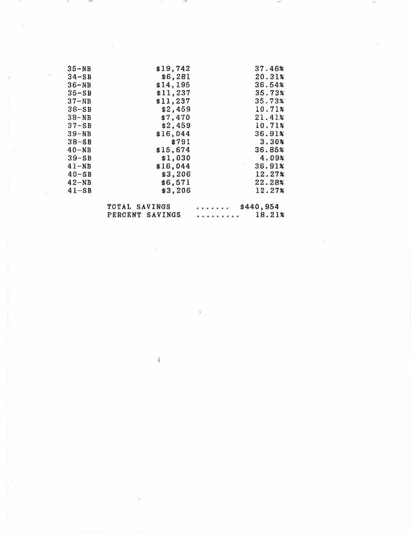
35-NB 34-SB 36-NB 35-SB 37-NB 36-SB 38-NB 37-SB 39-NB 38-SB 40-NB 39-SB 41-NB 40-SB 42-NB 41-SB
$19,742 $6,281
$14,195 $11,237 $11,237
$2,459 $7,470 $2,459
$16,044 $791
$15,674 $1,030
$16,044 $3,206 $6,571 $3,206
TOTAL SAVINGS PERCENT SAVINGS
37.46% 20.31% 36.54% 35.73% 35.73% 10.71% 21.41% 10.71% 36.91%
3.30% 36.85%
4.09% 36.91% 12.27% 22.28% 12.27%
$440,954 18.21%

I ....