g.v. naidis institute for high temperatures russian academy of sciences moscow, russia lorentz...
TRANSCRIPT

G.V. Naidis
Institute for High Temperatures Russian Academy of Sciences
Moscow, Russia
Lorentz Center workshop, Leiden, October 2007
Simulation of the controlled streamer-to-spark transition
Simulation of the controlled streamer-to-spark transition
Introduction
Two types of streamer-induced discharges in
atmospheric-pressure air are considered:
- controlled streamer-to-spark transition
(prevented spark);
- repetitively pulsed nanosecond discharge

Positive streamers in point-plate gaps in air
R.S. Sigmond and M. Goldman, Electrical Breakdown and Discharges in Gases, pt. B. Plenum, N.Y., 1983, p.1
(a) Propagation of primary streamer,
(b) primary streamer followed by development of the post-streamer channel,
(c) streamer-to-spark transition
1) Thermal mechanism: a lowering of the gas density inside
the channel due to expansion of the heated plasma (Marode
e.a.1979,1985; Bayle e.a.1985).
This factor is ineffective at τbreakdown « τexpansion = rch/csound
~ 6x10² ns (for channel radius rch ~ 0.02 cm).
2) Kinetic mechanism: accumulation of active particles
changing the ionization balance (Rodriguez e.a.1991;
Eletskiy e.a.1991; Lowke 1992; Aleksandrov e.a.1998;
Naidis 1999).
Mechanisms resulting in streamer-to-spark transition

Simulation of channel evolution after bridging the gap
Telegraph equations for the electric field E and current I :
the capacitance C and electrical conductivity Σ per unit length are
,),(
),(),(
tz
tzItzE
z
,
),(
t
tzC
z
I
Czzt
),(
/~ 2field d
Time required for re-distribution of the electric field is
(d is the gap length)
eener 2chπ,
)/ln(2
1
chrdC

The electric field distributions after streamer bridges the gap
Air, 1 bar, 300 K
d = 1 cm
U = 19 kV
The distribution of electric field becomes nearly uniform along the channel at t ~ 102 ns
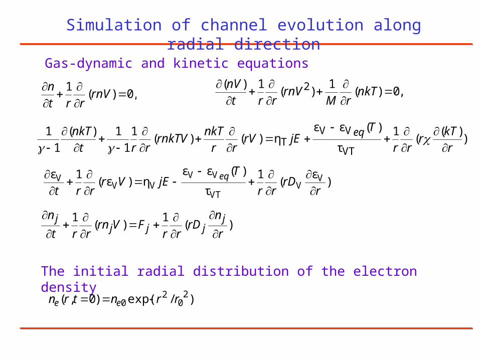
Simulation of channel evolution along radial direction
Gas-dynamic and kinetic equations
,0)(1
)(1)( 2
nkTrM
rnVrrt
nV,0)(
1
rnVrrt
n
The initial radial distribution of the electron density
),ε
(1
τ
)(εεη)ε(
1ε VV
VT
VVVV
V
rrD
rr
TjEVr
rrteq
)(1
)(1
r
nrD
rrFVrn
rrt
n jjjj
j
)/exp()0,( 20
20 rrntrn ee
),)(
(1
τ
)(εεη)()(
1
1
1)(
1
1
VT
VVT r
kTr
rr
TjErV
rr
nkTrnkTV
rrt
nkT eq
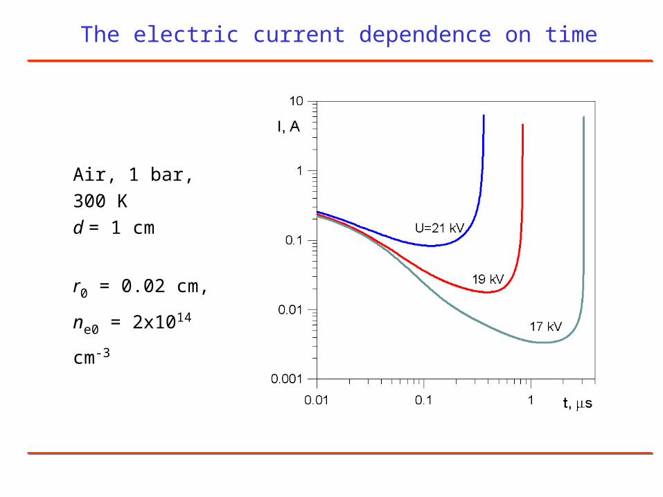
Air, 1 bar, 300 K
d = 1 cm
r0 = 0.02 cm,
ne0 = 2x1014 cm-3
The electric current dependence on time
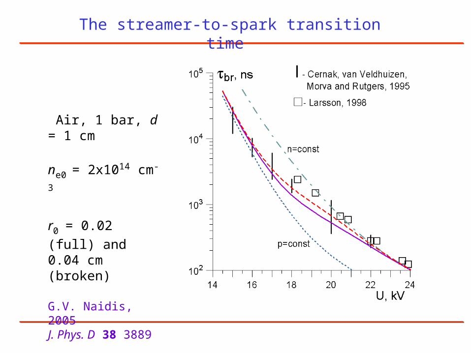
Air, 1 bar, d = 1 cm
ne0 = 2x1014 cm-3
r0 = 0.02 (full) and
0.04 cm (broken)
G.V. Naidis, 2005 J. Phys. D 38 3889
The streamer-to-spark transition time
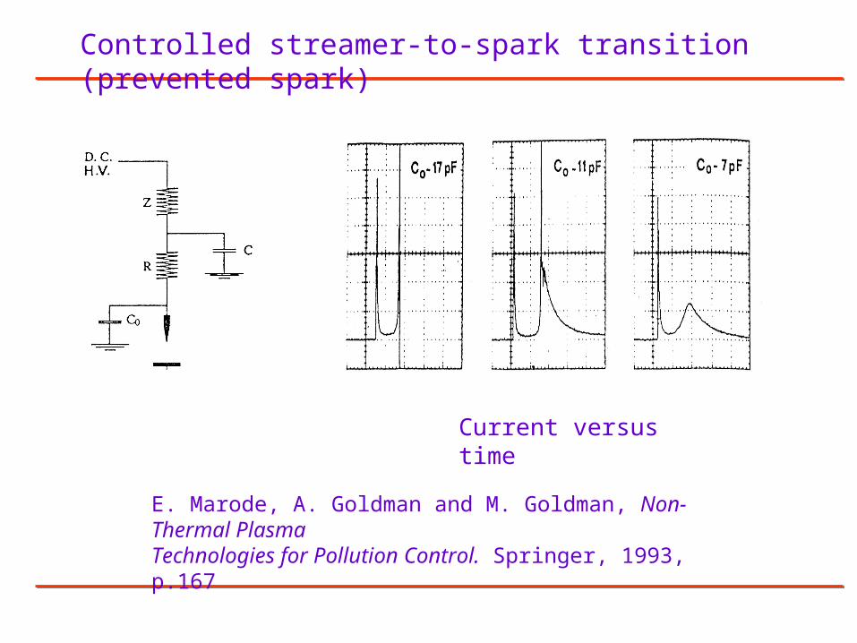
E. Marode, A. Goldman and M. Goldman, Non-Thermal Plasma Technologies for Pollution Control. Springer, 1993, p.167
Controlled streamer-to-spark transition (prevented spark)
Current versus time
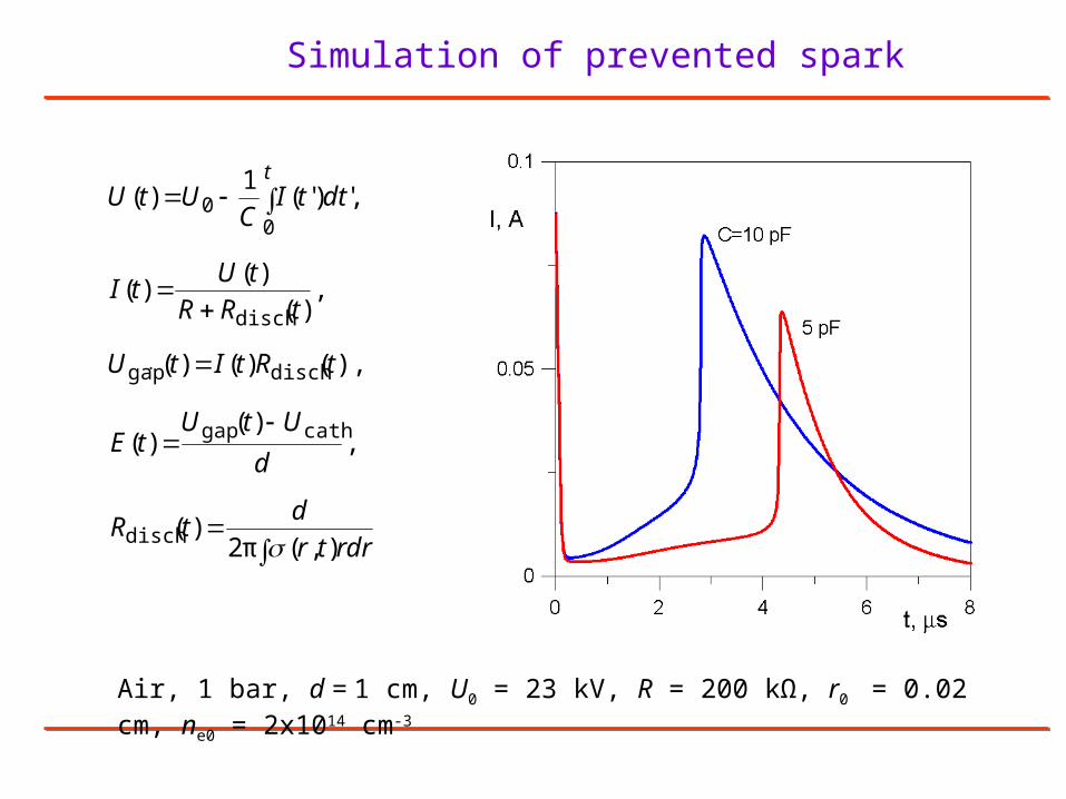
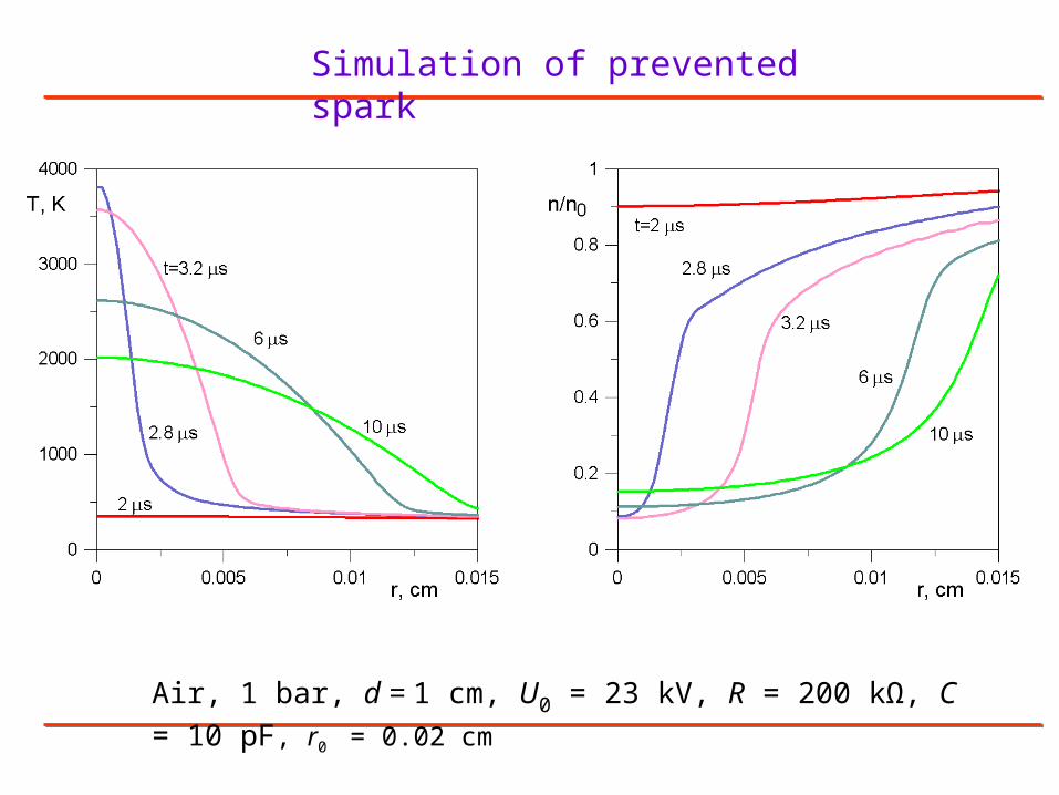
Simulation of prevented spark
Air, 1 bar, d = 1 cm, U0 = 23 kV, R = 200 kΩ, r0 = 0.02 cm, ne0 = 2x1014 cm-3
rdrtr
dtR
d
UtUtE
tRtItU
tRR
tUtI
dttIC
UtUt
),(π2)(
,)(
)(
),()()(
,)(
)()(
,')'(1
)(
disch
cathgap
dischgap
disch
00
.
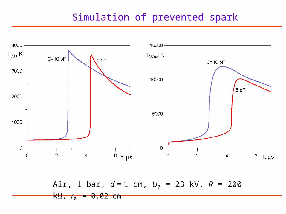
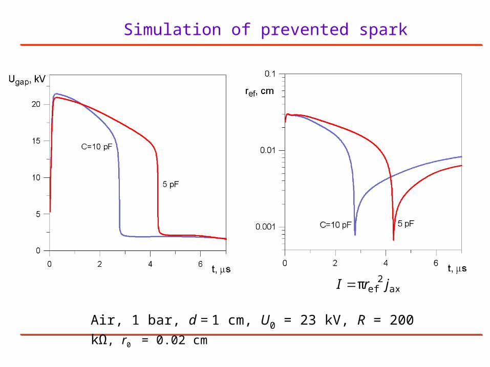
Simulation of prevented spark
Air, 1 bar, d = 1 cm, U0 = 23 kV, R = 200 kΩ, r0 = 0.02 cm
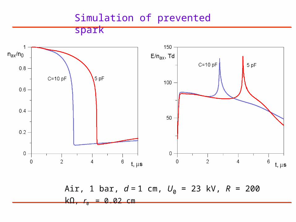
Simulation of prevented spark
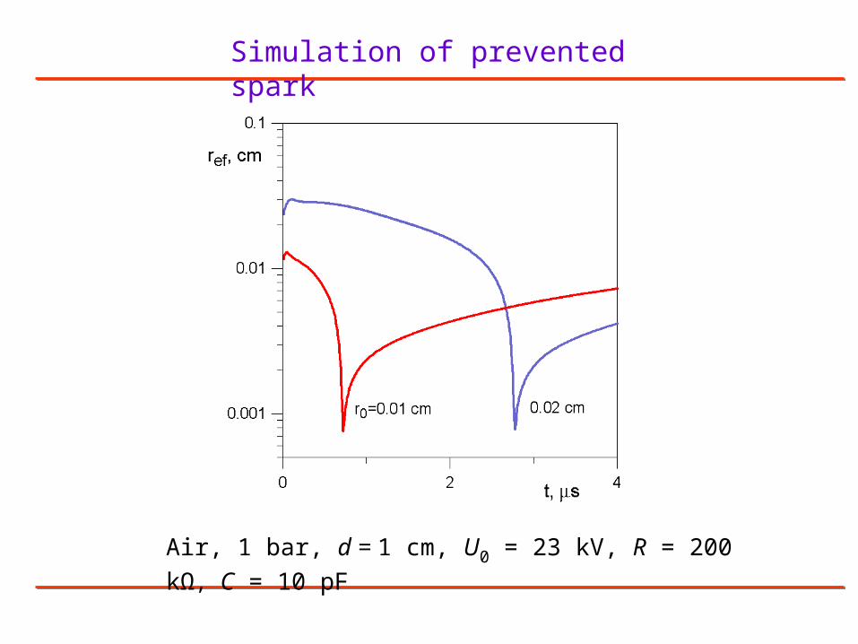
Air, 1 bar, d = 1 cm, U0 = 23 kV, R = 200 kΩ, C = 10 pF, r0 = 0.02 cm
Simulation of prevented spark
Air, 1 bar, d = 1 cm, U0 = 23 kV, R = 200 kΩ, r0 = 0.02 cm
ax2
efπ jrI
Simulation of prevented spark
Air, 1 bar, d = 1 cm, U0 = 23 kV, R = 200 kΩ, r0 = 0.02 cm
Simulation of prevented spark
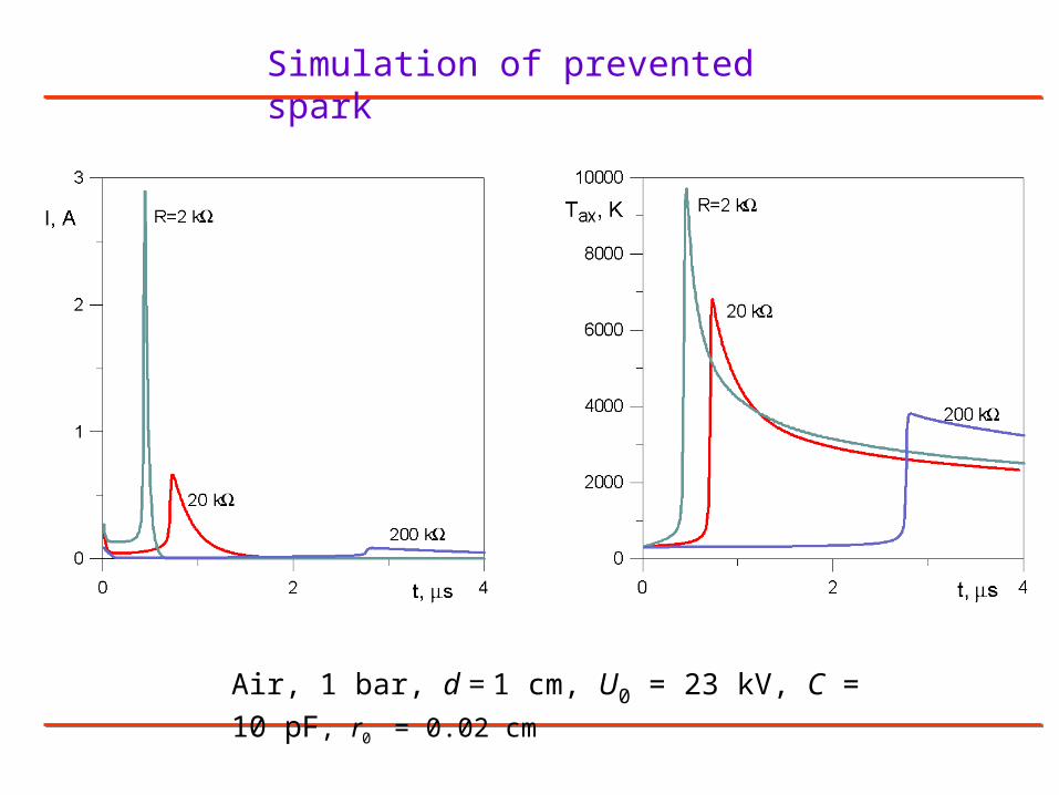
Air, 1 bar, d = 1 cm, U0 = 23 kV, R = 200 kΩ, C = 10 pF
Simulation of prevented spark
Air, 1 bar, d = 1 cm, U0 = 23 kV, R = 200 kΩ, C = 10 pF
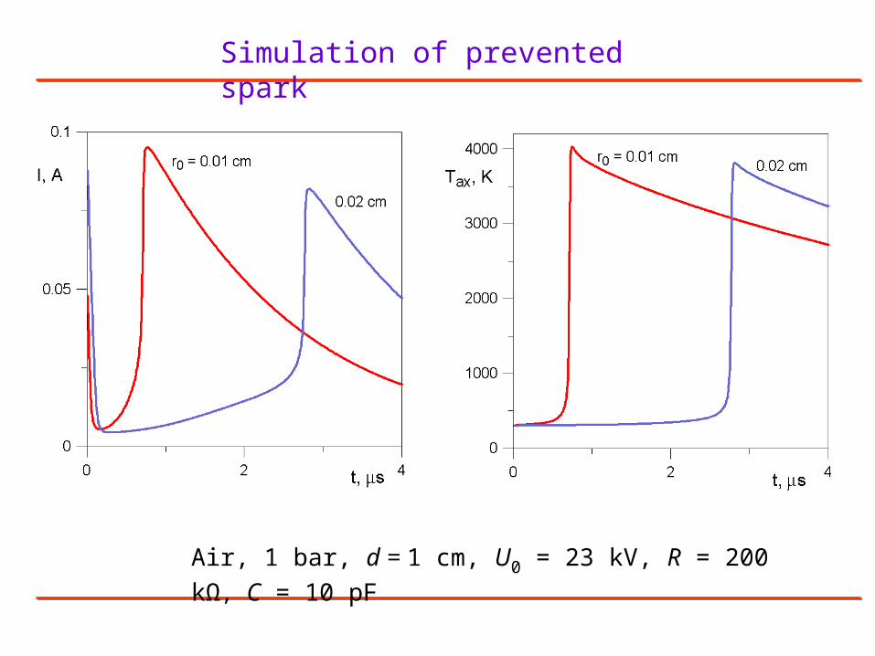
Simulation of prevented spark
Air, 1 bar, d = 1 cm, U0 = 23 kV, C = 10 pF, r0 = 0.02 cm
Air, 1 bar
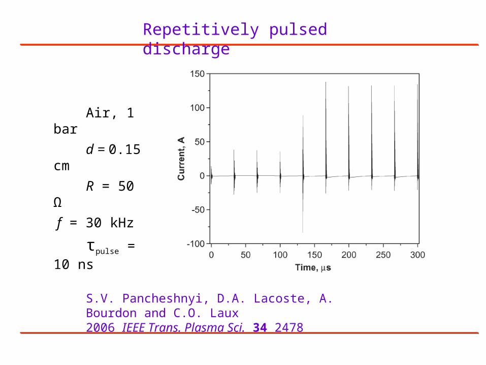
d = 0.15 cm
R = 50 Ω
f = 30 kHz
τpulse = 10 ns
Repetitively pulsed discharge
S.V. Pancheshnyi, D.A. Lacoste, A. Bourdon and C.O. Laux 2006 IEEE Trans. Plasma Sci. 34 2478
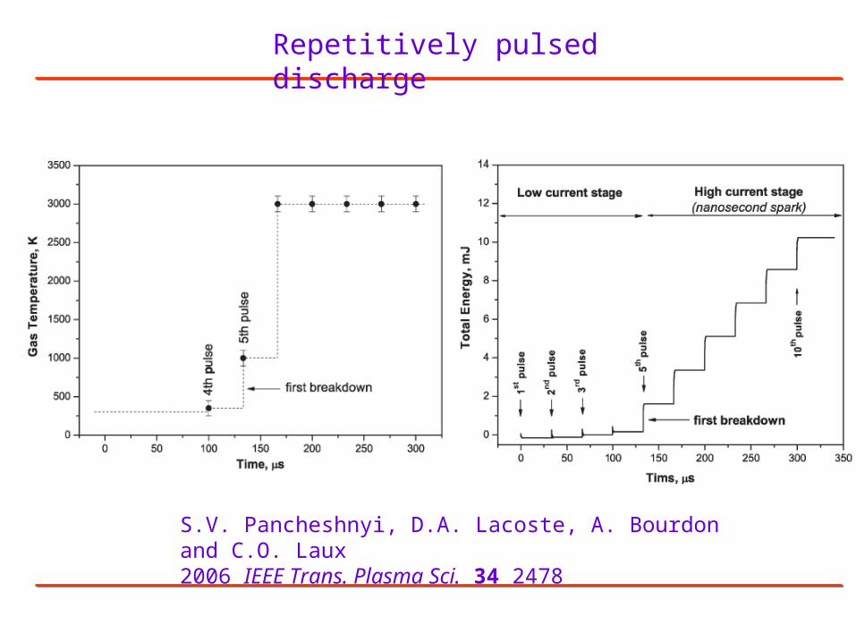
Repetitively pulsed discharge
S.V. Pancheshnyi, D.A. Lacoste, A. Bourdon and C.O. Laux 2006 IEEE Trans. Plasma Sci. 34 2478
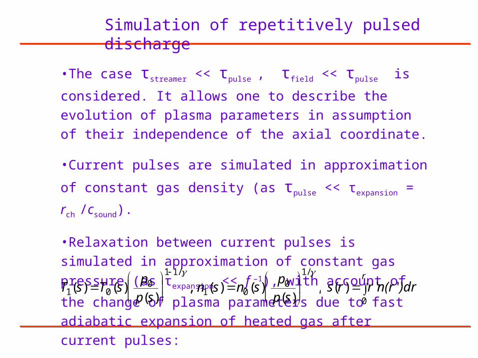
Simulation of repetitively pulsed discharge
•The case τstreamer << τpulse , τfield << τpulse is considered. It allows one
to describe the evolution of plasma parameters in assumption of their
independence of the axial coordinate.
•Current pulses are simulated in approximation of constant gas
density (as τpulse << τexpansion = rch /csound).
•Relaxation between current pulses is simulated in approximation of
constant gas pressure (as τexpansion << f –1), with account of the change
of plasma parameters due to fast adiabatic expansion of heated gas
after current pulses:
,)(
)()( ,)(
)()(/1
001
/110
01
sp
psnsn
sp
psTsT
r)drn(rrrs
0''')(
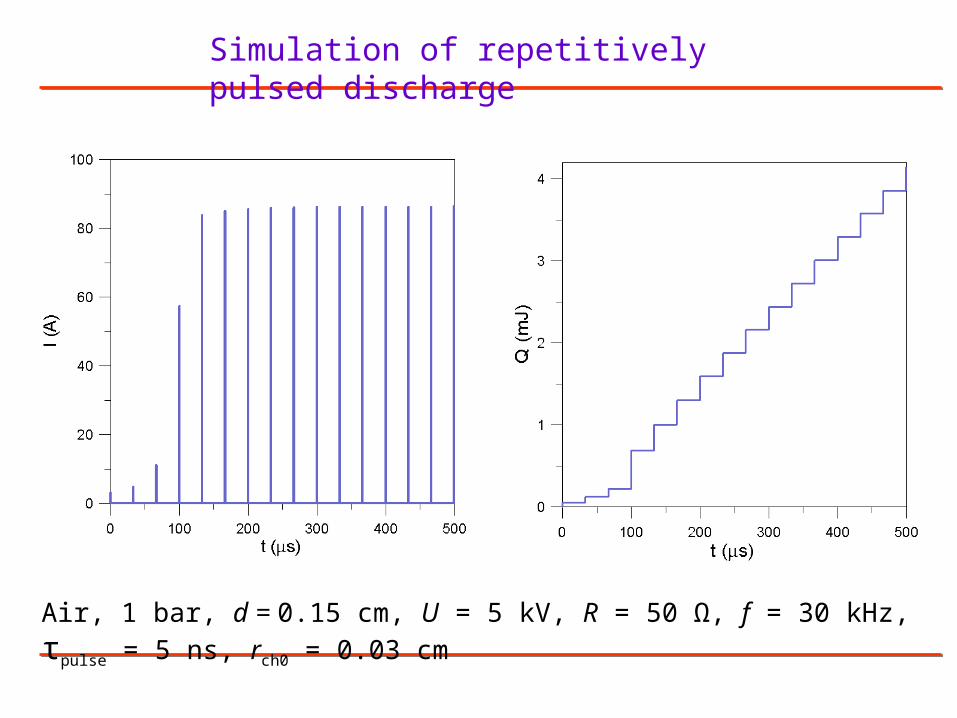
Simulation of repetitively pulsed discharge
Air, 1 bar, d = 0.15 cm, U = 5 kV, R = 50 Ω, f = 30 kHz, τpulse = 5 ns, rch0 = 0.03 cm

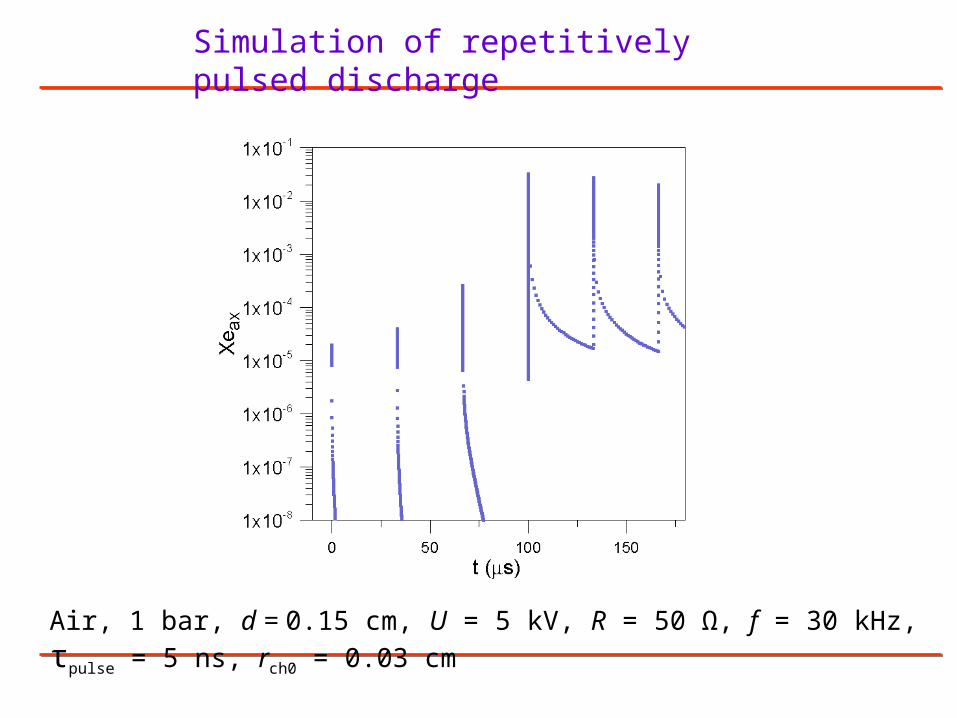
Simulation of repetitively pulsed discharge
Air, 1 bar, d = 0.15 cm, U = 5 kV, R = 50 Ω, f = 30 kHz, τpulse = 5 ns, rch0 = 0.03 cm
Simulation of repetitively pulsed discharge
Air, 1 bar, d = 0.15 cm, U = 5 kV, R = 50 Ω, f = 30 kHz, τpulse = 5 ns, rch0 = 0.03 cm

Simulation of repetitively pulsed discharge
Eighth current pulse
Air, 1 bar, d = 0.15 cm, U = 5 kV, R = 50 Ω, f = 30 kHz, τpulse = 5 ns, rch0 = 0.03 cm

Simulation of repetitively pulsed discharge
Air, 1 bar, d = 0.15 cm, U = 5 kV, R = 50 Ω, f = 30 kHz, τpulse = 5 ns, rch0 = 0.03 cm
Simulation of repetitively pulsed discharge
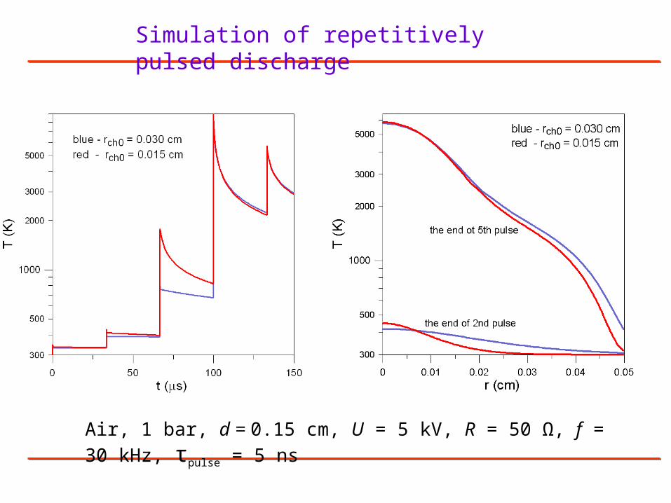
Air, 1 bar, d = 0.15 cm, U = 5 kV, R = 50 Ω, f = 30 kHz, τpulse = 5 ns
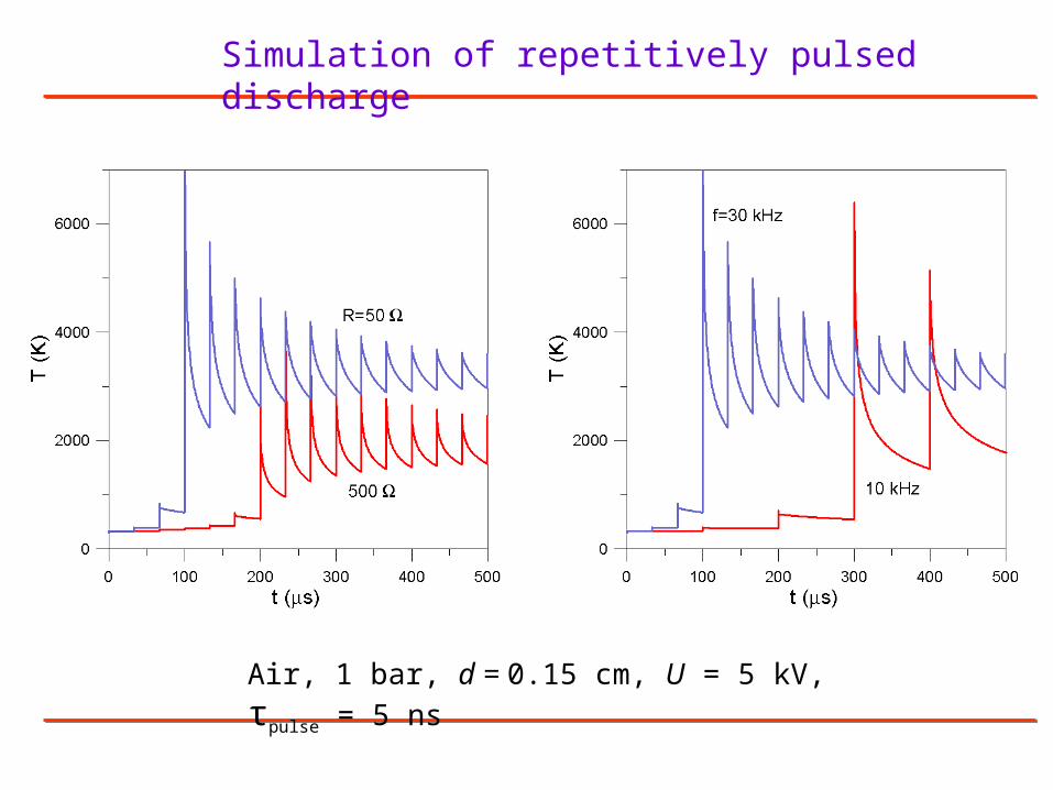
Simulation of repetitively pulsed discharge
Air, 1 bar, d = 0.15 cm, U = 5 kV, τpulse = 5 ns
Conclusion
Results of simulation show that by changing the
applied voltage with time (in a single pulse, or a
number of repetitive pulses) it is possible to control
evolution of plasma inside the channels after
streamer bridging the gap, and to produce non-
thermal plasma with variable parameters.