gyroscope technology, status and trends - unibw.de · gyroscope technology, status and trends...
TRANSCRIPT

GYROSCOPE TECHNOLOGY, STATUS AND TRENDS
Wilhelm F. Caspary
I n s t i t u t fu r Geod~sie, Un ivers i t~ t der Bundeswehr MUnchen
ABSTRACT
Af te r a sketch of h i s to ry of gyroscope technology, the dynamic law
of a gyroscope and i t s spec ia l i za t ion to the suspended gyrocompass
are ou t l ined . The equations of motion of a north-seeking gyro are
reviewed forming the base for observat ion techniques. Fol lowing a
s t a t e - o f - t h e - a r t repor t , the re la t i ons between the observables and
the f i na l azimuth are f u l l y discussed and act ions and precautions
required fo r precise resu l ts are proposed. With modern ins t ru -
ments and observat ion methods i t is present ly possible to deter -
mine an azimuth wi th a standard dev ia t ion of 3" to 6" w i th in less
than one hour. The pr inc ip les of non-ro ta t ing op t ica l gyroscopes
are presented and t h e i r po tent ia l as a l t e rna t i ves to conventional
instruments is discussed.
1. INTRODUCTION
Gyroscopes as instruments for measuring azimuths have always had t h e i r place on the
f r inge of geodesy. In the ea r l y days of th i s technology i t r e a l l y was a venture to carry
out observat ions, since the equipment was voluminous and heavy, the procedure time consum-
ing and the accuracy of the resu l ts unsa t is fac to ry . In add i t ion to t h a t , the average sur-
veyor did not understand the way the gyroscope works. Not that the theory is d i f f i c u l t ,
but i t is beyond every day experience. By reason of th is s i t ua t i on gyro technology ac-
quired the reputat ion of being an exo t ic subject hard ly of use fo r surveying app l i ca t ions .
This s t i l l ex is ts although the scene has changed completely.
Modern mechanical gyros are handy and provide the azimuth with an accuracy of a few
seconds of arc in less than one hour. The dynamics of gyroscopes has been t reated at
length in numerous papers, admi t ted ly sometimes more confusing than en l igh ten ing , but the
in terested surveyor can eas i l y f ind su i tab le presentat ions of the theory. In sp i te of
these s i gn i f i can t advances the acceptance has remained on a low l eve l .
Present ly op t ica l gyroscopes have a t t rac ted widespread a t t en t i on as an a l t e r n a t i v e to
mechanical gyros in nav igat ion plat forms. Their performance has a l ready reached a leve l
which makes them rate as po ten t ia l candidates fo r a completely new generat ion of nor th-
seeking instruments.

164
2. HISTORICAL BACKGROUND
The dynamic behaviour of a spinning wheel had been known fo r a long t ime, when the
French phys ic is t L. FOUCAULT made his famous experiment in 1852. He suspended a gimballed
ro tor from an ear th- f ixed support using a thread, such that the axis of the ro tor was
forced to remain in a horizontal plane. The object ive was to prove that the earth rotates
and that therefore, caused by the torque due to the precession in the ear th 's g rav i ta t i on -
al f i e l d , the spin axis would turn towards true north. Unfortunately the experiment
fa i l ed because i t was impossible at that time to maintain the required angular ve loc i ty
(LAUF 19631)). Nevertheless, th is was the b i r t h of a north-seeking instrument fo r which
FOUCAULT coined the name gyroscope and which has become increasingly important fo r naviga-
t ion and geodesy.
FOUCAULT's experiment turned the at tent ion of many famous sc ien t is ts of the las t cen-
tury to the theory of the gyroscope. Authors l i ke CAYLEY, EULER, KELVIN, KLEIN, SOMMER-
FELD and GRAY made valuable contr ibut ions to the dynamics of th is instrument. But i t
took unt i l 1908 before working gyrocompasses were constructed by ANSCHUTZ-K~MPFE in Ger-
many and SPERRY in the USA. These single-gyro compasses were designed fo r the navigation
of vessels, but i t turned out that they were too sensi t ive to the ship 's r o l l i n g . Further
research and experiments led to two- and three-gyro compasses showing much bet ter per-
formance. The f ina l breakthrough was achieved by ANSCHDTZ in 1922 wi th a f loated spher i-
cal gyroscope meeting a l l needs for use at sea.
Para l le l ing th is development f i r s t studies and experiments were conducted aiming at
the use of gyroscopes for bore-hole and tunnel measurements. These e f fo r t s were supported
and advocated by the mining surveying author i t ies in Germany. The f i r s t experimental ins t ru- ment was constructed by SCHULER in 1921 and tested in coal mines. Already in 1926 an im-
proved gyroscope was b u i l t con jo in t l y by ANSCHUTZ and BREITHAUPT and in 1936/37 ANSCHUTZ
presented the th i rd generation. A l l these instruments remained on the prototype level
and were not adopted by the surveying community, because the accuracy was unsat is factory,
the weight was too heavy and the observational procedures were too complicated.
In 1948 a new s ta r t was made at the Mining Universi ty Clausthal by RELLENSMANN. The
fo l lowing period is noted by a steady progress and by noteworthy contr ibut ions of d i f f e ren t
companies, having led to the current arsenal of gyroscopic instruments fo r azimuth deter-
mination. There are bas ica l ly two types of instruments: the gyroscope attachments and
the gyrotheodol i tes. In Western Europe mainly three companies o f fe r gyrocompasses fo r
precis ion observations on the c i v i l market which are sui tab le fo r geodetic app l ica t ions:
I ns t i t u te of Mining Surveying (WBK), Bochum, FRG
Hungarian Optical Company (MOM), Budapest
Wild, Heerbrugg, Switzerland
The instruments which are best documented and probably of most widesPread usage are the attachment GAK i of Wild, the gyrotheodol i tes Gi-BI and Gi-B11 of MOM and the MW 50
(MW 50 a) and Gyromat of WBK.

165
THE FREE GYROSCOPE
The f ree gyroscope consists of a fas t spinning ro to r which is mounted in a set of
mbals such that i t is decoupled from a l l ro ta t ions of the support. Under the assump-
on that the gimbal bearings are f ree from f r i c t i o n and tha t the instrument is balanced
d s t r i c t l y symmetrical so tha t the three axes coincide with the p r i nc i p l e axes of iner -
a and in te rsec t in the cent repoint of the r o t o r , the spin axis w i l l i n d e f i n i t e l y main-
in i t s o r i en ta t i on in i n e r t i a l space. To an observer on the earth the spin axis appar-
t l y moves on a cone with an axis pa ra l l e l to the ro ta t i on axis of the earth. Figure I
~ows a gimbal mounted elementary ( f ree) gyro.
1
3
1 Outer Gimbal Axis
2 Inner Gimbal Axis
3 Spin Axis
a Rotor
b Inner Gimbal (F loat )
c Outer Gimbal
d Frame (Base)
Figure 1 Schematic of a gimbal mounted f ree gyroscope (FABECK 1980)
I f a torque is appl ied in the d i rec t i on of the 2-axis then the angular momentum of
the ro to r changes i t s d i rec t i on and the 3-axis begins a motion about the 1-axis which is
known as precession of the gyro. The f ree gyro t r i e s to a l ign the spin axis wi th the d i -
rec t ion of the appl ied torque.
In the English l i t e r a t u r e th is type of gyroscope is usua l ly denoted asa two degrees of
freedom (TDF) gyro. I t represents the basic concept of the gyros used to control the a t -
t i t ude of i n e r t i a l plat forms.
The suppression of one degree of freedom of the ro to r r e l a t i v e to the frame y ie lds
the single degree of freedom (SDF) gyro. A special version of th i s type is the nor th-
seeking gyroscope or gyrocompass. The gyroscope of Figure i could be converted in to a

166
gyrocompass i f the 1-axis is kept in the d i rec t i on of the local ve r t i ca l and the 3-ax is in
the hor izonta l plane, i . e . the ro ta t i ona l degree of freedom about the 2-ax~s is suppressed.
4. THE SUSPENDED GYROCOMPASS
I f a gyroscope is suspended from an earth
f i xed support such tha t the spin axis is con-
st ra ined to remain in a hor izonta l plane (F i -
gure 2), then a torque caused by the force of
g r a v i t y acts upon the instrument. The force
changes i t s d i rec t i on r e l a t i v e to an i n e r t i a l
coordinate system wi th the angular v e l o c i t y of
the ro ta t i ng earth. The ro to r reacts with an
angular motion (precession) towards the d i rec -
t i on of the earth rate vector . The i n e r t i a o f
the system w i l l prevent the spin axis from
stopping when i t reaches the meridian. In-
stead i t w i l l move fu r ther un t i l the d i rec-
t i ona l force exceeds the i n e r t i a and causes
the system to swing back. Thus an o s c i l l a t i o n
t l
Figure 2 Suspended meridian- seeking gyroscope
Figure 3 Decomposition of the earth rate vector in a local ve r t i ca l and hor izonta l component as funct ions of the l a t i t u d e
/
/ /
/ 3
i e
2
Figure 4 The hor izonta l component of Figure 3 resolved in d i rec- t ions of the 3- and 2-axis of the gyro

167
is b u i l t up, which would las t i n d e f i n i t e l y i f the system was free of f r i c t i o n . Since the
motion is constrained to the horizontal plane, only the component m cos m of Figure 3 is
e f fec t i ve , where ~ is the earth rate and ~ the la t i t ude . Figure 4 shows the view from
space at the horizontal plane. The horizontal component of the earth rate is decomposed
in two components, the one point ing in the d i rec t ion of the 3-axis (spin axis) is
cos~ cos~ and the other one point ing opposite to the d i rec t ion of the 2-axis is
cos~ sins wi th ~ being the momentary angle between spin axis and local meridian. The
exact equation of the precession of the gyroscope is rather involved. I t expresses the re-
su l tant e f fec t of the i ne r t i a of the ro to r , the ro ta t ing grav i ty vector and the tors ion of
the suspension band. Since i t is well documented in several t ex t books e.g. DEIMEL (1950) 2)
Figure 5
1 Suspension Tape (band)
2 Mast
3 Gyro Motor ( ro to r )
4 l l luminated Moving Mark
5 Col l imator
6 Reading Scale
7 Forced Centering to the Theodoli te
8 Clamping Ring
9 Upper Tape Clamp
Observation window showing two posi t ions of the moving mark
Cross-section of a gyro attachment (Wild GAK 1)
The moving mark (4) osc i l l a tes wi th the ro tor (3) about the ver t i ca l axis. The centre l i ne of the o s c i l l a t i o n is the d i rec t ion of the mer id ianexcept for some correct ions explained l a te r . The observa- t ion aims at the determination of th is centre l i ne , which is achieved by taking time and/or posi t ion information of the moving mark wi th respect to reading scale.
168
and FABECK (1980) 3) in th is paper no der ivat ion is given. The discussion of the equation
in the next section fol lows bas ica l ly the approach selected by VANICK (1972) 4) .
For a bet ter understanding at f i r s t , an actual gyroscope attachment is presented in
Figure 5, showing some construct ive de ta i l s and introducing the relevant terms.
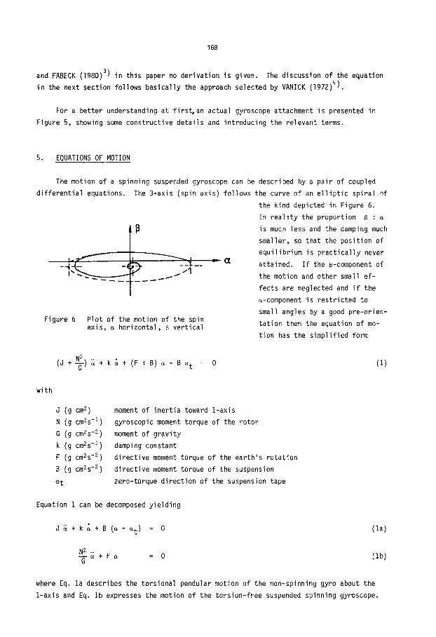
5. EQUATIONS OF MOTION
The motion of a spinning suspended gyroscope can be described by a pa i r of coupled
d i f f e r e n t i a l equations. The 3-axis (spin axis) fo l lows the curve of an e l l i p t i c sp i ra l ~f
Figure 6
..111
Plot of the motion of the spin axis, m hor izonta l , B ver t i ca l
the kind depicted in Figure 6.
In r e a l i t y the proport ion B : a
is much less and the damping much
smaller, so that the posi t ion of
equ i l ib r ium is p r a c t i c a l l y never
at ta ined. I f the B-component of
the motion and other small e f -
fects are neglected and i f the
a-component is res t r i c ted to
small angles by a good pre-or ien-
ta t ion then the equation of mo-
t ion has the s impl i f ied form
(J + ~ ) ~ + k ~ + (F + B) a - B a t 0 ( i )
wi th
J (g cm z)
N (g cm2s - I )
G (g cm2s "2)
k (g cm2s " I )
F (g cm2s "2)
B (g cm2s "2)
s t
moment of i ne r t i a toward 1-axis
gyroscopic moment torque of the ro tor
moment of g rav i ty
damping constant
d i rec t i ve moment torque of the ear th 's ro ta t ion
d i rec t i ve moment torque of the suspension
zero-torque d i rec t ion of the suspension tape
Equation 1 can be decomposed y ie ld ing
J ~ + k ~ + B (~ - ~t) = 0
N 2 .. - - ~ + F ~ = 0 G
( la )
( Ib)
where Eq. la describes the tors ional pendular motion of the non-spinning gyro about the
i - ax i s and Eq. Ib expresses the motion of the to rs ion- f ree suspended spinning gyroscope.

169
The so lu t ion of Eq. 1 resu l ts in the expression fo r the hor izonta l pendular motion of
the real spinning gyroscope
s = so + C e - k t cos(~pt + c) (2)
where C and c are i n teg ra t i on constants depending on the i n i t i a l condi t ions. The equi-
l i b r i um pos i t ion deviates from t rue north due to the t w i s t o f the suspension tape by
= B st (3) ~o B + F
The damping fac to r ~ is given by
= k/2 (J + -~-) (4)
and the frequency m of the swing is
2 _ B + F X2 (5) ~P N 2
J + ~ G
These equations describe the hor izonta l component of the o s c i l l a t i o n of the suspended
gyroscope with an accuracy bet te r than required fo r the determinat ion of azimuths, but they
have to be modif ied fo r p rac t ica l use, since s , s 0 and s t re fe r to t rue nor th, whi le
the observat ions are car r ied out wi th respect to zero of the reading scale of the gyro or
of the theodo l i t e .
6. OBSERVATION METHODS
There are six methods of f ind ing north using a suspended gyroscope (THOMAS 1982)s). The
o s c i l l a t i o n curve of the moving mark as observed through the co l l ima to r is depicted in
Figure 7 as a funct ion of t ime.
The equation of th i s damped simple harmonic motion is given by
: AN' + A e -~ ( t - tO) s i n ( ( t - t o ) -~) (6)
where aN' is the required angle between the zero l i ne N' of the observat ion scale and
the centre l i ne M of the o s c i l l a t i o n . A is the amplitude and T the per iod of the mo-
t i on . Since the damping fac to r ~ is usua l ly neg lectab ly smal l , three independent obser-
vat ions su f f i ce to uniquely determine AN' , A and T . The c lass ica l method is the ob-
servat ion of three consecutive reversal po ints , az, a2, and a 3 fo r example. The we l l -
known SCHULER Mean is then employed to ca lcu la te the required scale value of the centre
l i ne of o s c i l l a t i o n

170
(I
_ _ t" 1
a3 a 5
Figure 7 Osci l la t ion of the moving mark plotted against time
AN' al + 2a2 + a3 : ( 7 )
4
The observation o f t rans i t times was f i r s t proposed by SCHWENDENER (1964) 6) • I f three
consecutive t rans i ts through a selected graduation l ine ~ are timed using a stop watch
with lap timing f a c i l i t i e s , then the di f ference A~ between th is l ine and the centre l ine
o f osc i l l a t i on is computed from
tz z = t 2 - t I , t23 + t12 = T
t23 = t 3 - t 2 , t23 - t12 = At
A~ A At T (8)
where again l inear damping is assumed. The amplitude A is read at the turning point.
A combination of two t rans i t times and one reversal point reading can be used to de- termine AN' as has been shown by THOMAS (1982) s). Let t l b e t h e f i r s t t rans i t time, next
the turning point al has to be read and f i n a l l y the second t rans i t time t 2 at the same
selected graduation l ine ~ is taken. I f the period T is known then
t12 = t z - t I , p = 2 sin 2 2T t12
A~ = (~ + a l [p -1 ] ) / p
(9)
can be used to local ize the centre l ine of osc i l l a t i on on the reading scale, where l inear
damping has been assumed.

171
Al l three basic methods can be used in the clamped and in the t racking mode.
The t racking mode requires a special theodol i te wi th a double tangent screw, so that
the observer can rotate the theodol i te continuously such that the gyro mark remains in co-
incidence with the zero l ine of the reading scale. The reversing point readings and/or the
t r a n s i t times are taken at the horizontal c i r c l e of the theodol i te . This observation meth-
od has the advantage that no tors ion is applied to the suspension tape, so that the motion
is governed by Eq. lb. On the other hand the t racking requires much sk i l l and patience and
leads to systematic errors i f not performed per fec t l y . The f i rm MOM has developed an auto-
matic t racking system which is incorporated in the gyroscope series Gi-B2. In spi te of the
repor tedly good resul ts the manufacturing of these instruments has been given up.
I t seems that general ly the observations in the clamped mode are favoured. The d is-
advantage of having to consider the tors ional o s c i l l a t i o n of the system is outweighed by
the absence of any interference of the observer wi th the o s c i l l a t i n g system. To improve
the accuracy of the resul ts the basic methods as out l ined above have been fur ther devel-
oped. The reversal point method is usual ly employed taking more than the minimum of three
turning point readings. The accuracy of the readings can be upgraded by using special op-
t i ca l micrometers and the redundant observations are evaluated in a s t r i c t least squares
adjustment.
The same trend can be observed for the t r a n s i t method. Precise recording watches are
used which make i t possible to take the times of t r a n s i t at a l l graduation l ines , so that
as many as 60 observations become avai lab le for each swing. The times are taken to one
hundredth of a second. A rigorous adjustment on the basis of Eq. 6 y ie lds the required
resul ts (CASPARY/SCHWINTZER 1981)7).
7. AUTOMATED OBSERVATION
Since the observation of t r ans i t times and turning points is wearisome, time-consuming
and requir ing experienced observers, e f fo r t s were soon made to automate the measuring pro-
cedure. F i rs t experiments were made in Canada with a MOM Gi-BI and a WILD GAK 1 and simi-
l a r l y at CERN with the WILD attachment. The resul ts were very encouraging as a consider-
able gain in accuracy and a reduction of observation time could be achieved. Today two
automated gyroscopes of high precision are on the market.
MOM of fers the Gi-B11 gyrotheodol i te , which is equipped with two photodiodes. The
t r a n s i t of the moving mark through these diodes is automat ical ly timed by a quarz-stabi -
l i zed impulse counter. The resul ts appear on a d isp lay and can be recorded or d i r ec t l y
t ransferred to the computer (HP 41 C) i f connected. The posi t ion of the centre l i ne of
the o s c i l l a t i o n is computed from Eq. 10 arequir ing the observation of one complete period.

172
The observation has to be repeated at least once. Figure 8 explains the terms of Eq. 10.
COS T I - COS T3 t i ~ AN' = ~0 , T i - i = 1 ,3
cos T l + cos T3 T ' ( i0)
~'"' D I
I
II
,I /
• , i T
p
AML N,
Figure 8 Automated time reading, MOM Gi-B l l
WBK has automated the gyrotheodol i te MW 77 and se l ls i t under the name Gyromat. For
the determination of the centre l ine of o s c i l l a t i o n a novel in tegrat ion method is used.
The swing is continuously sensed by a photo-diode equipped with an opto-e lect ron ic pick-
o f f . The signal of one period only is used. I t is f i l t e r e d and integrated, the resu l t is
(Z
N
M
N'
T
tow th-
Figure 9 Integrat ion method of signal sens- ing in the Gyromat (EICHHOLZ 1978)
torquer which d i rec ts a reference mark towards true
l i t e .
a measure fo r the required angle AN'
as can be seen from Figure 9. The ob-
servation process is automat ical ly tem-
perature corrected and contro l led by
cer ta in funct ions.
On a lower level o f accuracy, fur -
nishing m i l i t a r y requirements mainly,
BODENSEEWERK GERAETETECHNIK (BGT) has
developed an automatic gyro attachment.
The d i rec t i ve moment of the spinning
gyro is sensed and converted into a
proport ional current which generates
a counter moment suppressing the pre-
cession. The same current dr ives a
north to be picked o f f by the theodo-

173
8. CALCULATION OF THE AZIMUTH
The astronomic azimuth A' r e l a t i v e to the t rue meridian is computed from Eq. 11.
Figure I0 shows the meaning of the terms which are discussed in due d e t a i l l a t e r .
A' = s 0 + AN' + E + Bp + ~r (11)
rY 0 Z
M
ZHC
E F E R E N C E ~
M Centre Line of O s c i l l a t i o n
TZP Tape Zero Pos i t ion
N' Zero o f the Reading Scale
PO Pre -o r ien ta t i on Reading
ZHC Zero of the Hor izonta l C i rc le
w Angle on the Horizontal C i rc le
: Angle on the Reading Scale
Computed Angle
Figure 10 Graph of the quan t i t i e s requi red to compute the azimuth
The zero- torque d i r e c t i o n o f the tape according to Eq. i i s given by
s t : s o + AN' -
subs t i t u t i ng s o of Eq. 3 y i e l ds
B s t AN' - s t - B + F
B + F (AN' - c) s t : F
which f i n a l l y resu l t s in
B (AN' - ~) S 0 =
(12)
(13)
Hence the computation requires the knowledge of E and of the r a t i o c = B/F .
174
is the zero-torque d i rec t i on of the tape on the reading scale. I t can be deter -
mined by any of the methods out l ined in sect ions 5 and 6 observing the o s c i l l a t i o n of the
non-spinning gyro. Since the tape zero pos i t ion is not very stable i t is usua l ly measured
before and a f t e r the observat ion of the spinning gyro. I f the d i f fe rence is smal l , then
the mean is used for the correct ion of Eq. 13 otherwise the l as t value should be preferred.
The r a t i o c is a constant which var ies wi th l a t i t ude . The manufacturers provide a tab le
of c as the resu l t of a ca l i b ra t i on fo r each ind iv idua l instrument. As SCHWENDENER
(1964) ~) has shown, the fac to r c is a d i r ec t funct ion of the periods of the o s c i l l a t i o n s
of the gyro in the t rack ing mode T t and in the clamped mode T c .
2 2 B T t - Tc - = c - ( 1 4 ) F 2
T c
Other methods of determinat ion are discussed in VANICEK (1972) 4),
The angle E in Eq. 11 is an instrument constant which re la tes the zero l i ne of the
reading scale to the hor izonta l c i r c l e of the theodo l i t e . This constant is usua l ly deter-
mined on an astronomical reference l i ne . The determinat ion has to be repeated at regular
i n t e r va l s i f accurate resu l ts are required. Modern instruments e.g. the MOM Gi-BII and the
Gyromat, possess an instrument f i xed reference mi r ro r enabl ing the measurement of changes
of E together with each azimuth observat ion.
The las t two terms of Eq. 11 are theodo l i tes readings, ~r a f t e r s ight ing the re fe r -
ence object, and Bp a f t e r the p re -o r i en ta t i on of the gyroscope.
Since A' refers to the momentary d i rec t i on of the ear th 's ro ta t i on a x i ~ a l l stand-
ard reduct ions known from astronomic azimuth determinat ion have to be appl ied to convert
A' in to a bearing defined in a selected coordinate system.
9. ACCURACY CONSIDERATIONS
On assessing the performance of gyroscopes i t is p a r t i c u l a r l y important to d is t ingu ish
prec is ion and accuracy and to consider the environmental circumstances at the observat ion
s i t e . Measurements in a labora to ry or a tunnel y i e l d more consistent resu l ts than those in
the f i e l d . Most of the standard dev iat ions being reported on in the l i t e r a t u r e are com-
puted from repeat measurement and hence measures of prec is ion. Figure 10 shows the number
o f elements, a l l a f fected by random and systematic e r ro rs , which are put together to make
up the azimuth. I t is obvious that the resu l t cannot have an accuracy of one second of arc
or be t te r . But i t is possible to create favourable cond i t ions , to apply well designed pro-
cedures and to exercise care in order to get optimal resu l t s .
Two theodo l i te readings (Bp, B r) belong to each azimuth, they should be taken twice
at the beginning and twice at the end of each azimuth determinat ion. Dif ferences indicate

175
i n s t a b i l i t i e s of the set-up. Optimal resu l ts requi re observat ion p i l l a r s , t r ipods enable
only second best resu l ts .
No azimuth can be more accurate than the instrument constant E . The methods of de-
terminat ion and of checking E have been out l ined a l ready in section 8. Experiments have
shown tha t E changes wi th temperature, there fore a c a l i b r a t i o n in a temperature con-
t r o l l e d labora to ry should be carr ied out i f f i e l d measurements are considered.
The determinat ion of the centre l i ne in the non-spin mode (~) should be car r ied out
before and a f t e r the observat ion of the equ i l i b r ium pos i t ion of the spinning gyro (AN'). I f
a t r a n s i t method is employed, then three f u l l swings fo r E and two fo r AN' are adequate.
The constant c = B/F of Eq. 13 should be determined fo r each observat ion s i t e . I f a
chronometric method is appl ied, then the period T c of Eq. 14 is ava i l ab le wi thout ex t ra
measurements, on ly T t has to be measured, which can be done by t iming four to f i ve re-
versal points.
Some fu r the r ru les to be exercised in order to get good resu l ts are:
Swinging of the gyro wi thout spinning fo r ha l f an hour e l iminates tors ions and defor -
mations of the tape being imposed by clamping fo r t ranspor t .
A f ter spin-up of the gyro a cer ta in time is needed fo r the instrument to a t t a i n tem-
perature equ i l ib r ium. Dependent on the a i r temperature th is can require up to one hour fo r
MOM and WILD instruments. The Gyromat needs less time since i t only s l i g h t l Y warms up due
to the low spinning ra te .
The tape zero pos i t ion (E) should be regulated near to zero to minimize systematic e f -
fects on the o s c i l l a t i o n . For the same reason the p re -o r i en ta t i on should be performed as
wel l as possible to get a small value of AN' .
Some authors recommend measuring wi th two d i f f e r e n t p re -o r ien ta t i ons symmetrical to
the zero l i ne .
Af ter these act ions the actual observat ions can s t a r t . Regular checks and cor rec t ions
of the ve r t i ca l ax is o f the instrument cont r ibu te to the q u a l i t y o f the resu l t s .
A pro tec t ion from cer ta in environmental fac tors l i k e magnetism, movement of a i r by
v e n t i l a t i o n o~ wind, and v ib ra t ions caused by heavy machinery or t r a f f i c is des i reable.
This can be achieved by c a r e f u l l y select ing the s i te and the time of measurements and by
sh ie ld ing the instrument.
I f these rules are obeyed and the best observat ion procedures are employed then the
observed azimuths have t y p i c a l l y the fo l low ing standard dev ia t ions . The WILD GAK 1 mounted
on a s ing le second theodo l i t e using extended chronometric methods or special devices fo r
reading the scale provides the azimuth wi th 5" to 6" standard dev ia t ion . The automated
gyrotheodol i tes Gyromat and Gi -B l l perform s l i g h t l y be t te r , namely wi th an accuracy of 3"
to 4".

176
The precision of resul ts for measurements in a lab are usual ly bet ter by a factor of
two.
10. NON-CONVENTIONAL GYROSCOPES
Since the ear ly 1960s opt ica l gyroscopes have been under development. These ins t ru-
ments do not have moving par ts , are of apparently somple design and seem to have the
potent ia l of be t te r performance in respect to resolut ion and dynamic range, as compared
with the conventional mechanical gyroscopes. But the f i r s t prognoses that these new
instruments would soon completely replace the ro ta t ing machines had to be revised, since
numerous problems were encountered in the development of prototypes. Today the laser
gyro is on an operational leve l . I t is used in strap-down platforms for a i r c r a f t navi-
gat ion (Boeing 757, 767 and Airbus 310), where a wide measuring range is more important
than a high precis ion.
The basic idea of opt ica l gyroscopes is due to the French physic is t SAGNAC, who b u i l t
in 1913 the f i r s t r ing inter ferometer to study the nature of l i g h t . I f a r ing in te r fe ro -
meter is mounted on a turntable and rotated then a l i g h t beam t r ave l l i ng wi th the ro ta t ion
w i l l need more time to ar r ive back to the source than a beam t r a v e l l i n g against the rota-
t ion . This is the so-cal led SAGNAC e f fec t , which can easi ly be computed i f minor correc-
t ions due to the general r e l a t i v i t y theory are neglected. The di f ference AL of the op t i -
cal path length of the two beams is
4F AL = - - m (15) C
where F is the area enclosed by the path, c the ve loc i ty of l i g h t and ~ the angular
ve loc i t y of the r ing wi th respect to i n e r t i a l space. The path d i f ference can be measured
i n d i r e c t l y by observing the f r inge pattern produced by the i n t e r f e r i ng beams, see
Figure 11.
2
<J
1 Light Source (LASER)
2 Mirror
3 Beam S p l i t t e r
4 Fringe Pattern
Figure 11 Schematic of a r ing in te r fe ro - meter according to SAGNAC (RODLOFF 1982)8).

177
Since c is constant, the path d i f ference AL is d i r e c t l y proport ional to the area
F and the angular ve loc i t y m of the set-up. The technical problem is to generate a
measureable e f fec t , which is achieved by two d i f f e ren t approaches.
The f i be r -op t i c gyroscope at ta ins the required s e n s i t i v i t y by use of a large area F .
Optical f i be r wi th a length up to I000 m is wrapped into a co i l of very low volume. The
f i r s t ro ta t ion rate sensors of th is type are now being readied fo r app l i ca t ion . Figure 12
shows the concept of a f i be r -op t i c gyro as developed by SEL. I t has a dynamic range of
400°/s, a repea tab i l i t y of 50 ppm and a d r i f t of less than 3°/h.
The laser gyro consists of a cav i ty as depicted in Figure 13.
F--I,
Figure 12
F = 100 cm 2
I t converts the path
Fringe pattern
Polarizet~n. ng monornode " ~ r
length d i f ference in a frequen-
cy s ignal , which can be observed
Schematic of a f i b e r - o p t i c gyroscope (SEE)
and ~ = 0.633 ~m , being eas i ly measureable.
more eas i ly . The mir rors create
a closed path ca l ib ra ted to be
an integral mul t ip le of the wave
length thus forming an opt ica l
resonator. Rotation of the r ing
laser induces a change of the
eigenfrequencies of the two
beams t r ave l l i ng in opposite d i -
rect ions. Their beat frequency
is proport ional to the rate of
the resonator. I t is measured
by observing the f r inge pattern
produced by superimposing the
beams. The ear th 's rate of
15°/h generates a beat frequency
of I Hz in a laser gyro of
i Mir ror
2 D ie lec t r i c Mir ror
3 Anode
4 Cathode
5 Length Control
6 Cervi t Block
7 Corner Prism
8 ReadouC Detector
Figure 13 Schematic of a gyro block assembly (RODLOFF 1982) 8}

178
The main problem with the laser gyro is the so-cal led lock- in e f fec t , which prevents
the measurement of small angular ve loc i t i es . The reason fo r th is e f fec t is the tendency of
coupled osc i l l a t o r s to swing on a common frequency i f the eigenfrequencies d i f f e r only a
l i t t l e . Thus input rates below a certa in threshold produce a zero output. A remedy is to
mechanically d i ther the laser block with a frequency above the lock- in rate.
As already mentioned, laser gyros are operational as a t t i t ude sensors fo r i ne r t i a l
plat forms. They have an e f fec t ive range of 10 -2 °/h to lO00°/so Prognoses of today are
that the s e n s i t i v i t y to smaller rates w i l l improve and w i l l become comparable to the best
mechanical gyroscopes. Since the i r production is less expensive, they may possibly one day
compete with conventional suspended gyroscopes. Suitably mounted, so that rotat ions about
a horizontal and a ver t i ca l axis are possib le, opt ica l gyros are capable of sensing the
t rue north d i rec t ion and the geographic l a t i t ude .
11. CONCLUSION
Over the las t two decades s ign i f i can t advances have occured in the technology of con-
ventional suspended gyroscopes. The accuracy of determining north has improved consider-
ably due to the advent of new instruments, the in t roduct ion of more e f fec t i ve chronometric
observation methods and to automating the observation of the centre l ine of osc i l l a t i on .
The same actions have s imp l i f i ed the measurements and reduced the time required, so that i t
has become possible to measure an azimuth wi th in 15 to 60 minutes wi th a standard deviat ion
of 3" to 6".
In future~opt ical gyroscopes may replace the conventional instruments. Within 25
years laser gyros have reached a level of performance rendering them sui table for appl ica-
t ion in strap-down platforms. F iber-opt ic gyros have been under development for 10 years,
seemingly meeting now the performance requirements of i n e r t i a l navigat ion. Both rea l i za -
t ions of the SAGNAC e f fec t hold the promise of g iv ing higher performance at lower cost.

179
REFERENCES
I ) LAUF, G.B.: The gyrotheodolite and i ts application in the mining industry of South Africa. Journal of the South African Inst i tute of Mining and Metallurgy, pp. 349-386, 1963.
2) DEIMEL, R.F.: Mechanics of the Gyroscope. Dover, New York 1950.
3) von FABECK, W.: Kreiselger~te. Vogel-Verlag, WUrzburg 1980.
4) VANICEK, P.: Dynamical Aspects of the Suspended Gyrocompass. The Canadian Surveyor (26), pp. 77-83, 1972.
5) THOMAS, T.L.: The Six Methods of Finding North Using a Suspended Gyroscope. Survey Review (26), pp. 225-235, 1982.
6) SCHWENDENER, schr i f t 1964.
H.R.: Beobachtungsmethoden fur Aufsatzkreisel. Schweizerische Zeit- fur Vermessung, Kulturtechnik und Photogrammetrie (62), pp. 365-375,
7) CASPARY, Wo, P. SCHWINTZER: An Extension of Chronometric Gyroscope Observation Methods. The Canadian Surveyor (35), pp. 364-372, 1981.
8) RODLOFF, R.: Vom Pendel zum Laserkreisel. Ortung und Navitation, pp. 398-411, 1982.
BIBLIOGRAPHY
CASPARY, W.: Moderne Vermessungskreisel - Leistungsf~higkeit und Einsatzm~glichkeit. In Proc. of IX. Internationaler Kurs fur Ingenieurvermessungen, Graz 1984.
CASPARY, W., H. HEISTER: Problems in Precise Azimuth Determinations with Gyrotheodolites. In Proc. of XVII. Kongress FIG, 609.2, Sofia 1983.
EICHHOLZ, K.: Moderne Vermessungskreisel ger~tetechnische Konzeption und Entwicklungs- stand. In Proc. of IX. Internationaler Kurs fur Ingenieurvermessung 1984
EICHHOLZ, K., R. SCHAFLER: "Gyromat" an Automatic Gyro-Theodolite of High Precision, In- fluences of Interference Parameters on Northing Accuracy and Counter-Measures. In Proc. of 2nd ISS, pp. 613-625, Banff 1981
HALMOS, F.: High, Precision Measurement and Evaluation Method for Azimuth Determination with Gyrotheodolites. In Manuscripta Geodaetica (2), pp. 213-231, 1977
HALMOS, Fo: Evaluation of Automatized Gyrotheodolite Measurements with Special Respect to MOM Gyrotheodolites. In Acta Geodeat., Geophys. et Montanist., Acad. Sci. Hungary (16), pp. 27-39, 1981
RUEGER, J.M.: Inert ia l Sensors, Part I: Gyroscopes. Edited by K.P. Schwarz, Division of Surveying Engineering, The University of Calgary, Publ. 30002, Calgary 1982.