halion sonic se (3.1.0) 3.1.0 - operation manual sonic se offers two types of presets: ... for more...
TRANSCRIPT

Operation Manual
Matthias Klag, Michael Ruf
Cristina Bachmann, Heiko Bischoff, Christina Kaboth, Insa Mingers, Matthias Obrecht, Sabine Pfeifer, BenjaminSchütte, Marita Sladek
This PDF provides improved access for vision-impaired users. Please note that due to the complexity and numberof images in this document, it is not possible to include text descriptions of images.
The information in this document is subject to change without notice and does not represent a commitment onthe part of Steinberg Media Technologies GmbH. The software described by this document is subject to a LicenseAgreement and may not be copied to other media except as specifically allowed in the License Agreement. Nopart of this publication may be copied, reproduced, or otherwise transmitted or recorded, for any purpose,without prior written permission by Steinberg Media Technologies GmbH. Registered licensees of the productdescribed herein may print one copy of this document for their personal use.
All product and company names are ™ or ® trademarks of their respective owners. For more information, pleasevisit www.steinberg.net/trademarks.© Steinberg Media Technologies GmbH, 2018.
All rights reserved.
HALion Sonic SE_3.1.0_en-US_2017-12-07
Table of Contents
4 Introduction4 Conventions5 About the Program Versions5 How You Can Reach Us5 About the Documentation5 Setting Up7 Window Overview
9 Common Editing Methods9 Buttons9 Value Fields10 Using Key Commands10 Presets
12 Global Functions and Settings12 Plug-in Functions Section14 Plug-in Name and Steinberg Logo14 Toolbar14 Performance Controls15 Quick Controls15 Trigger Pads17 Options Page
22 Managing Your Sounds22 About Programs, Layers, and Multis22 Loading Programs23 Slot Rack24 Managing and Loading Files
29 Editing Programs29 Editing the Factory Content
32 Included Instruments32 Trip41 Flux
61 Automation61 Automation Page61 Setting Up Automation
63 MIDI Editing and Controllers63 MIDI Page64 MIDI Controllers
67 Mixing and Effect Handling67 Mix Page68 Effect Handling
69 Library Manager69 Library Manager Editor
73 Effects Reference73 Reverb Effects76 Delay Effects77 EQ Effects79 Filter Effects
86 Distortion Effects90 Pitch Shift Effects90 Modulation Effects100 Dynamics Effects108 Spatial and Panner Effects109 Legacy Effects
119 Using the Standalone Version of the Plug-In119 Making Preferences Settings119 Preferences Dialog120 Selecting the MIDI Input and the Audio Output121 Scratch Pad123 Loading a MIDI File123 Saving a MIDI File123 Master Volume
124 Index
3
Introduction
ConventionsIn our documentation, we use typographical and markup elements to structure information.
Typographical ElementsThe following typographical elements mark the following purposes.
PREREQUISITERequires you to complete an action or to fulfill a condition before starting aprocedure.
PROCEDURELists the steps that you must take to achieve a specific result.
IMPORTANTInforms you about issues that might affect the system, the connected hardware, orthat might bring a risk of data loss.
NOTEInforms you about issues that you should consider.
EXAMPLEProvides you with an example.
RESULTShows the result of the procedure.
AFTER COMPLETING THIS TASKInforms you about actions or tasks that you can perform after completing theprocedure.
RELATED LINKSLists related topics that you can find in this documentation.
MarkupBold text indicates the name of a menu, option, function, dialog, window, etc.
EXAMPLEIn the header of the plug-in panel, click the Preset Management button next to the preset namefield and select Load Preset.
If bold text is separated by a greater-than symbol, this indicates a sequence of different menusto open.
4

IntroductionAbout the Program Versions
Key CommandsMany of the default key commands, also known as keyboard shortcuts, use modifier keys, someof which are different depending on the operating system.
For example, the default key command for Undo is Ctrl-Z on Windows and Cmd-Z on macOS.When key commands with modifier keys are described in this manual, they are shown with theWindows modifier key first, in the following way:
● Windows modifier key/macOS modifier key-key
EXAMPLECtrl/Cmd-Z means: press Ctrl on Windows or Cmd on macOS, then press Z.
About the Program VersionsHALion Sonic SE comes in two versions: one is installed together with a Steinberg DAW, the othercan be downloaded for free from the Steinberg web site.
The version that comes with the DAW contains content, that is, programs, layers, presets, etc.and can be used out of the box.
The free version does not contain any content. This version can be used to load Steinbergcontent, user-generated content and 3rd party libraries without a Steinberg DAW. Furthermore,it can be used as a plug-in in any VST 3, VST 2, AU, and AAX compatible host and as a stand-aloneapplication.
How You Can Reach UsClick the Steinberg logo in the top right corner of the control panel to open a pop-up menucontaining items for getting additional information and help.
● This menu contains links to various Steinberg web pages. Select a link to open thecorresponding page. On the web pages, you can find support and compatibilityinformation, answers to frequently asked questions, links for downloading new drivers,etc.
About the DocumentationThe documentation is available online and can be downloaded in PDF format from steinberg.help
● To visit steinberg.help, enter steinberg.help in the address bar of your web browseror open HALion Sonic SE, click the Steinberg logo in the top right corner and select Help >HALion Sonic SE Help.
Setting UpThe following sections describe how to use the free version of HALion Sonic SE as a plug-in indifferent host applications.
NOTE
HALion Sonic SE can also be used as a standalone application.
5
IntroductionSetting Up
Using the Instrument in an AU-Compatible ApplicationThe AU version of HALion Sonic SE is installed in your AU plug-ins folder and lets HALion Sonic SEwork in an AU environment without any performance loss or incompatibilities.
For example, to load HALion Sonic SE as an AU instrument for Logic Pro, proceed as follows:
PROCEDURE
1. Open the Track Mixer and select the instrument channel that you want to use.
2. Click in the I/O field and select AU Instruments > Steinberg > HALion Sonic SE.
3. Select one of the available channel configurations.
Using the Instrument in an AAX-Compatible ApplicationThe AAX version of HALion Sonic SE is installed in your AAX plug-ins folder and makes HALionSonic SE available as AAX instrument in ProTools.
PROCEDURE
1. To use HALion Sonic SE as stereo multichannel plug-in, open the Track menu, and selectNew > Stereo > Instrument Track.
2. On the instrument track, click Inserts and select HALion Sonic SE from the multichannelplug-in > Instrument submenus.
Using the Instrument as Standalone ApplicationThe free version of HALion Sonic SE can be used as a standalone application, independentlyof any host application. In this case, you can connect the instrument directly to your audiohardware.
RELATED LINKSUsing the Standalone Version of the Plug-In on page 119
6
IntroductionWindow Overview
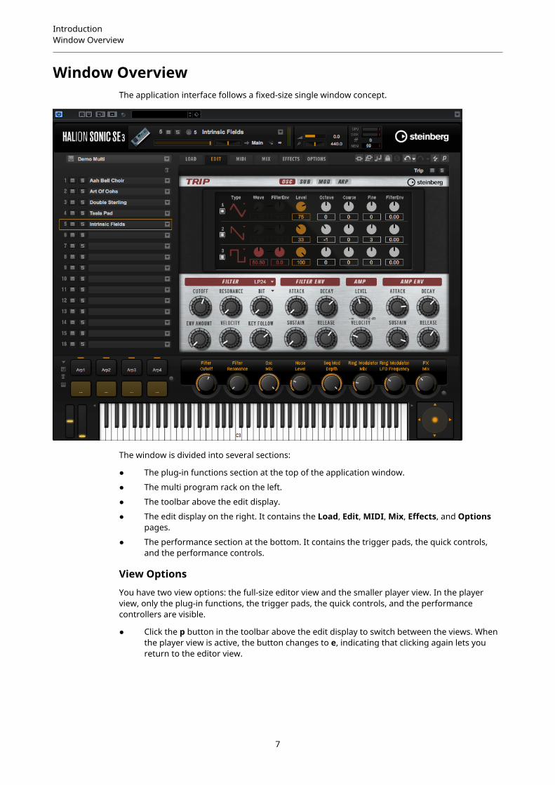
Window OverviewThe application interface follows a fixed-size single window concept.
The window is divided into several sections:
● The plug-in functions section at the top of the application window.
● The multi program rack on the left.
● The toolbar above the edit display.
● The edit display on the right. It contains the Load, Edit, MIDI, Mix, Effects, and Optionspages.
● The performance section at the bottom. It contains the trigger pads, the quick controls,and the performance controls.
View Options
You have two view options: the full-size editor view and the smaller player view. In the playerview, only the plug-in functions, the trigger pads, the quick controls, and the performancecontrollers are visible.
● Click the p button in the toolbar above the edit display to switch between the views. Whenthe player view is active, the button changes to e, indicating that clicking again lets youreturn to the editor view.
7

IntroductionWindow Overview
8

Common Editing Methods
ButtonsOn/Off Buttons
These buttons have two states: on and off. If you move the mouse over an On/Off button, itchanges its appearance to show that you can click it.
Push Buttons
Push buttons trigger an action and then go back to their inactive state. These buttons openmenus or file dialogs.
Value FieldsTo set a value, you have the following possibilities:
● Double-click in a value field, enter a new value, and press Enter.If the entered value exceeds the parameter range, it is automatically set to the maximumor the minimum value, respectively.
● Click in the value field and drag up or down.
● Position the mouse over a value field and use the mouse wheel.
● Click the up/down triangles next to the field.
● To set the parameter to its default value, Ctrl/Cmd-click the value field.
● To use a fader to adjust the value, Alt-click a value field.
● To enter musical values, such as key ranges or the root key, with your MIDI keyboard,double-click the value field, press a key on your MIDI keyboard, and press Return.
● To navigate to the next parameter, press Tab. To jump backwards to the previousparameter, press Shift-Tab.If no parameter is selected inside the focused view, pressing Tab always jumps to the firstparameter.
9

Common Editing MethodsUsing Key Commands
Using Key Commands
● To open the Key Commands dialog, open the Options page and click the Key Commandsbutton in the Global section.
The commands are arranged in a hierarchical folder structure on the left. When you opena category folder, the items and functions are displayed with any currently assigned keycommands.
● To set up a key command, select the function in the list, enter the key command in
the Type in Key field and click the Assign button to the right of the field. If this keycommand is already used for another function, this is displayed in the field below.
● To delete a key command, select the function in the list, select the key command in the
Keys list and click the Delete button.
● To search for a specific function, enter its name in the search field at the top of the dialog
and click the Start/Continue Search button.
NOTE
You can set up several key commands for the same function.
PresetsHALion Sonic SE offers two types of presets: section/module presets and VST presets. Section andmodule presets store and recall the setup of a specific component on the HALion Sonic SE panel.VST presets contain all information necessary to restore the complete state of the plug-in.
During setup, the factory presets are installed in a dedicated folder and a user folder is createdfor your own presets. The handling of presets is the same throughout the program.
NOTE
Factory presets are write-protected, but may be overwritten when a software update is executed.Presets in your user folder are never changed by the software update.
For more information on VST presets, see the Operation Manual of your Steinberg DAW.
10

Common Editing MethodsPresets
Handling Section and Module PresetsThe preset controls can be found throughout the program. The handling is always the same.
● To save a preset, click Save .
NOTE
You cannot overwrite factory presets. If you want to save changes made to a factorypreset, save the preset under a new name or in a new location.
● To load a preset, click the arrow icon and select a preset from the list.
● To delete a preset, click Delete .
NOTE
Factory presets cannot be deleted.
Handling VST Presets
Loading VST Presets
PROCEDURE
1. In the header of the plug-in panel, click the Preset Management button next to the presetname field and select Load Preset.
2. Do one of the following:
● Select a preset to load it.
● Double-click a preset to load it and close the preset loader.
Saving VST Presets
PROCEDURE
● In the header of the plug-in panel, click the Preset Management button next to the presetname field and select Save Preset.
11
Global Functions and Settings
Plug-in Functions SectionThe plug-in functions section at the top of the window gives you access to global functions thataffect both the currently loaded programs, and the general working of the plug-in.
The plug-in functions section contains the multi slot section, the program slot section, the mastersection, and the performance displays.
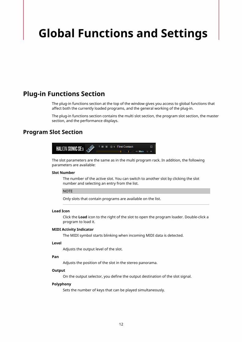
Program Slot Section
The slot parameters are the same as in the multi program rack. In addition, the followingparameters are available:
Slot NumberThe number of the active slot. You can switch to another slot by clicking the slotnumber and selecting an entry from the list.
NOTE
Only slots that contain programs are available on the list.
Load IconClick the Load icon to the right of the slot to open the program loader. Double-click aprogram to load it.
MIDI Activity IndicatorThe MIDI symbol starts blinking when incoming MIDI data is detected.
LevelAdjusts the output level of the slot.
PanAdjusts the position of the slot in the stereo panorama.
OutputOn the output selector, you define the output destination of the slot signal.
PolyphonySets the number of keys that can be played simultaneously.
12

Global Functions and SettingsPlug-in Functions Section
NOTE
One key can trigger several layers. On the performance meter, you can see howmany voices are triggered by your playing.
Program IconThe program icon indicates the sound category to which the program belongs. Itdepends on the category and subcategory tags that are specified for a program inthe MediaBay.
Master SectionThe master section can be used to set volume and tuning of the plug-in.
Master VolumeAdjusts the overall volume of the plug-in.
Master TuneYou can set the Master Tune slider from 415.3 Hz to 466.2 Hz, which equals -100cents to +100 cents.
Performance DisplaysThe meters and text displays indicate the system load of the plug-in.
CPUThis meter shows the processor load during playback. The more voices you play, thehigher the processor load. If the overload indicator lights up, reduce the Max Voicessetting on the Options page.
DiskThis meter shows the hard disk transfer load during the streaming of samplesor when loading presets. If the overload indicator lights up, the hard disk is notsupplying data fast enough. In such a case, open the Options page and adjust theDisk vs. RAM slider towards RAM or decrease the Max Voices setting.
PolyphonyThis display indicates the number of samples that are currently played back, to helpyou trace performance problems. For example, if you have to reduce the Max Voicessetting on the Options page, you can verify your settings by monitoring the numberof samples that are currently playing.
MemoryThis display indicates the overall amount of RAM that is currently used by the plug-in and the loaded programs. The number refers to the streaming buffer and thepreloaded samples. The MEM display helps you trace performance problems. Forexample, if you need to free up memory for other applications, you can adjust theDisk vs. RAM slider on the Options page toward Disk. You can verify your settingsby monitoring the MEM display.
13

Global Functions and SettingsPlug-in Name and Steinberg Logo
Plug-in Name and Steinberg LogoTo get information regarding the version and build number of the plug-in, click the plug-inlogo. This opens the About box. To close the About box, click it or press Esc on your computerkeyboard.
If you click the Steinberg logo in the top right corner of the plug-in interface, a pop-up menuopens. Select one of the options to navigate to Steinberg web pages containing information onsoftware updates, troubleshooting, etc.
ToolbarThe toolbar below the plug-in functions section contains controls for loading multi-programs onthe left, the buttons to switch between the different pages, and various useful global functions.
Global insert, AUX, and FlexPhraser buttonsUse these buttons to switch off all insert effects, AUX effects, and FlexPhrasers forthe whole plug-in at once. You can use this to compare sounds with and withouteffects or to use a preset without the FlexPhrasers, for example. FlexPhrasers are afeature of the full version of HALion. They add arpeggios and even complex musicalphrases to some programs of the factory content.
Lock buttonIf this button is activated, loading another program or layer does not overwrite thecurrent FlexPhraser and trigger pad settings.
MIDI ResetClick this button to stop playback and reset all MIDI controllers to their defaultvalues.
Undo/RedoTo undo or redo a single operation, click the Undo or Redo buttons. To undo or redomultiple operations, click the arrow next to the button to open the history and selectthe step to which you want to return.
Editor/PlayerThis button toggles between the two views: the full-size editor view (e) and thesmaller player view (p).
Performance ControlsThe performance controls are located in the lower part of the window.
Wheel Controls
To the left of the internal keyboard, the pitchbend wheel and the modulation wheel are located.
The modulation wheel is hardwired to MIDI controller #1, which is normally used as a source inthe modulation matrix, but can be used as a quick control as well.
14

Global Functions and SettingsQuick Controls
Keyboard
The virtual 88-note keyboard can be used to trigger MIDI notes. By clicking the keys at differentvertical positions you can control the note-on velocity. Furthermore, the keyboard displays keysthat are not used to trigger notes but act as key switches. The Shift Keyboard buttons to theleft and right of the keyboard shift the keyboard range by octaves. This allows you to display keyswitches that are located on lower keys, for example.
The following color scheme is used for the keys:
● Keys to which a key switch is assigned are shown in yellow.
● Keys to which a remapped key switch is assigned are shown in beige.
● Keys that are assigned to a trigger pad are shown in blue.
● Keys to which a loop trigger note is assigned are shown in green.
Sphere Control
The sphere is a two-dimensional control. It allows you to adjust two parameters simultaneously,by dragging the mouse horizontally (Sphere H) and vertically (Sphere V). Typically, twoparameters that belong together are assigned to the sphere, such as cutoff and resonance.
If parameters are assigned to Sphere H and Sphere V, triangles for indicating the horizontal andvertical axis are available.
You can reset the sphere to the center position using the corresponding options on the contextmenu.
● If Center Horizontal and/or Center Vertical are activated, the sphere returns to thecorresponding center position as soon as you release the mouse button.
Quick ControlsQuick controls allow you to remote-control any parameter inside the program.
For each program, eight quick controls are available. Furthermore, Sphere H, Sphere V, and themodulation wheel can also serve as quick controls.
To hear a sound without quick control assignments, you can bypass them temporarily by usingthe Bypass button to the right of the quick controls. This turns off the quick control assignmentsof the program.
Trigger PadsYou can use the trigger pads to trigger single notes or whole chords and to switch betweenFlexPhraser or arpeggiator variations.
Many of the programs that come with HALion Sonic SE make use of the trigger pads.
If a note or a chord is assigned to a pad, this pad turns orange. If a pad switches betweenvariations, the line above the pad turns orange.
15
Global Functions and SettingsTrigger Pads
● To trigger a pad, click on it.
PresetsPad presets save trigger notes and chord snapshots, but not the FlexPhraservariations. This means that you can exchange trigger notes and chords by loadingpresets without loosing your FlexPhraser variation settings.
BypassWith the Bypass Pads button to the right of the trigger pads, you can bypass theentire pads section. This deactivates any functionality you assigned to the triggerpads.
Assigning Trigger Notes to PadsYou can assign a MIDI note to a pad and trigger the pad by playing this note.
To define the trigger note, do one of the following:
● Right-click a pad, open the Assign Trigger Note submenu, and from the furthersubmenus, select the octave and note that you want to assign.
● Open the context menu for a pad, select Learn Trigger Note, and play the note on yourMIDI keyboard or click a key on the internal keyboard.The name of the assigned trigger note is displayed in the top left corner of the pad.
On the internal keyboard, keys that serve as trigger notes are shown in blue. These keys do notplay sounds, but trigger the corresponding pads instead.
● To remove a trigger note from a pad, right-click the pad and select Forget Trigger Note.
Assigning Chords or Notes to Trigger Pads
PROCEDURE
1. Right-click a pad and select Snapshot Chord.The pad starts blinking.
2. Do one of the following:
● Play a chord or a single note and then click the pad that is blinking to assign thechord or note to the pad.
● Drag a chord event from the chord track of your Steinberg DAW onto a trigger pad.This transfers the corresponding MIDI notes to the pad.If you drag a chord event onto the internal keyboard first, the corresponding chordis played back. This is useful to verify whether you selected the correct chord.
If you define a chord that contains a key switch, you can trigger the chord with a specificinstrument expression.If you add keys to a chord that also work as trigger notes, they trigger the underlying MIDInote instead of the trigger note.
RESULTTriggering the pad now plays the chord or note.
Removing Chords or Notes from Trigger Pads
PROCEDURE
● Right-click the trigger pad and select Clear Chord.
16
Global Functions and SettingsOptions Page
Default Trigger Note SettingsAssigned trigger notes are saved with each program to allow for maximum flexibility. However,you can save a fixed set of default trigger notes to reflect an existing hardware setup, forexample.
● To specify a default set of trigger notes, set up the trigger notes for all pads, right-click apad, and select Save Trigger Notes as Default.
● To activate the default trigger note settings, right-click a pad and select Use DefaultTrigger Notes.Now, changing programs or multi-programs does not change the trigger notes anymore.
If you deactivate Use Default Trigger Notes, the last set of trigger notes remains active. Toreturn to the trigger notes that were saved with the program, reload the program.
Assigning Key Switches to Trigger PadsTo use the pads for switching between expressions, assign them to the corresponding keyswitches.
PROCEDURE
● Right-click a pad, select Snapshot Chord, and play the key switch.
Naming PadsEntering names for pads allows you to get a better overview of their functionality, for example.
PROCEDURE
1. Right-click the pad to open the context menu and select Rename Pad.
2. Enter the new name and press Enter.
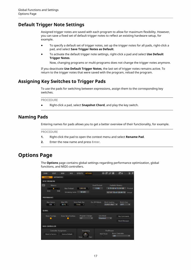
Options PageThe Options page contains global settings regarding performance optimization, globalfunctions, and MIDI controllers.
17
Global Functions and SettingsOptions Page
Disk Streaming Section
Some of the programs come with up to 1 GB of samples. That is a large amount of data and yourcomputer cannot load all samples completely into the RAM, especially if you are using all slots.Therefore, HALion Sonic SE loads only the initial milliseconds of each sample into RAM. You canspecify how much RAM should be used and how much HALion Sonic SE should rely on accessingthe hard-disk.
Balancing Disk vs. RAMUse the Balance slider to balance the hard disk versus the RAM usage.
● If you need more RAM for other applications, drag the slider to the lefttowards the Disk setting.
● If your hard disk is not supplying data fast enough, drag the slider to the righttowards the RAM setting.
NOTE
The Disk vs. RAM setting always applies to all plug-in instances. It is not saved withthe project. You set it up only once for your computer system.
Used Preload and Available MemoryThese displays provide information of the memory load in MB according to thecurrent balance slider setting.
Max PreloadDetermines the maximum amount of RAM that HALion Sonic SE uses for preloadingsamples. In most cases, the default values are sufficient. However, it may becomenecessary to reduce this value, for example, when working with other applications orplug-ins that require a lot of memory.
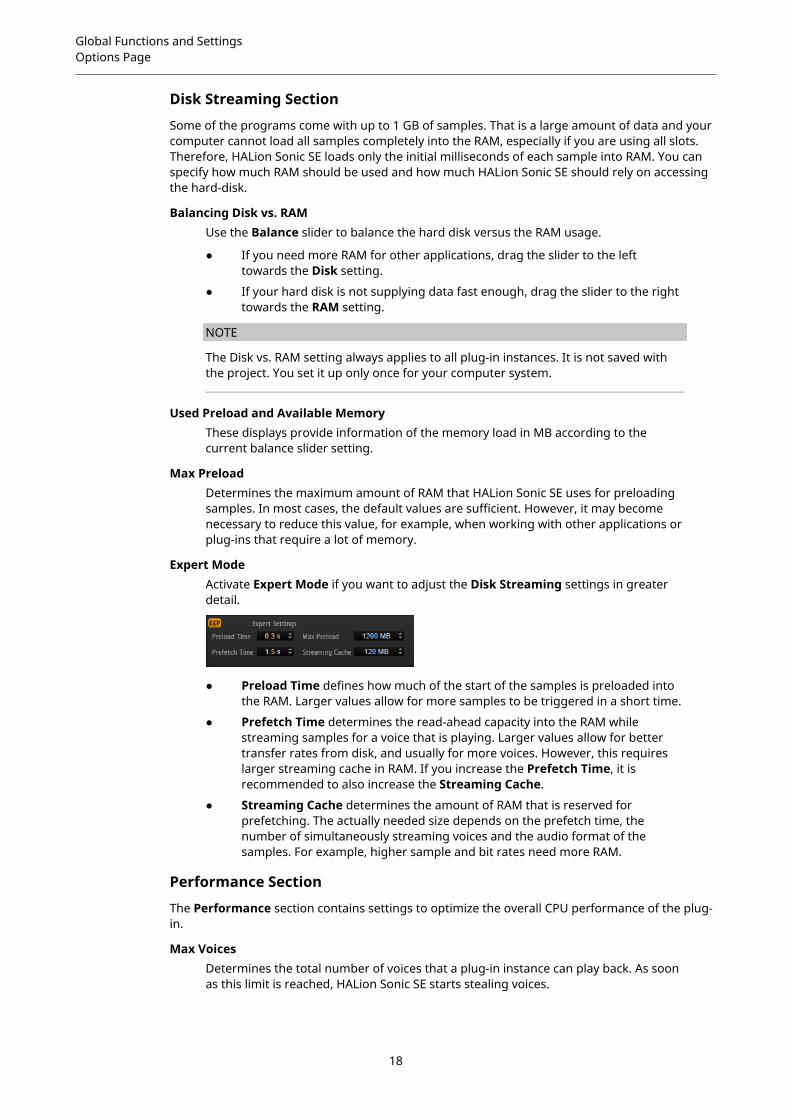
Expert ModeActivate Expert Mode if you want to adjust the Disk Streaming settings in greaterdetail.
● Preload Time defines how much of the start of the samples is preloaded intothe RAM. Larger values allow for more samples to be triggered in a short time.
● Prefetch Time determines the read-ahead capacity into the RAM whilestreaming samples for a voice that is playing. Larger values allow for bettertransfer rates from disk, and usually for more voices. However, this requireslarger streaming cache in RAM. If you increase the Prefetch Time, it isrecommended to also increase the Streaming Cache.
● Streaming Cache determines the amount of RAM that is reserved forprefetching. The actually needed size depends on the prefetch time, thenumber of simultaneously streaming voices and the audio format of thesamples. For example, higher sample and bit rates need more RAM.
Performance Section
The Performance section contains settings to optimize the overall CPU performance of the plug-in.
Max VoicesDetermines the total number of voices that a plug-in instance can play back. As soonas this limit is reached, HALion Sonic SE starts stealing voices.
18

Global Functions and SettingsOptions Page
Max CPUTo avoid clicks from CPU overloads, you can specify a maximum limit for the CPUload of the plug-in instance. HALion Sonic SE steals voices automatically when thislimit is exceeded. At a setting of 100 %, this parameter is deactivated.
NOTE
Because of the reaction time of the plug-in, it is possible that you get CPU peaks thatexceed the set limit. This can lead to artifacts, such as audio drop-outs. Therefore,it is good practice to set the Max CPU setting at a value a bit lower than actuallyneeded.
Voice Fade OutSets the time to fade out voices that need to be stolen because the Max Voicessetting or the Max CPU setting have been reached.
Osc ECO ModeActivate this option to run the oscillators of synth layers in ECO mode. In ECO mode,the oscillators use less CPU at the cost of producing more aliasing at higher pitches.If this option is activated, you can play more voices with synth layers.
Multi LoadingNormally, when loading multi-programs, the previous multi is kept in the RAM untilthe new multi has been completely loaded. Therefore, replacing a large multi byanother can lead to RAM overload on 32-bit systems.
● To clear a multi before loading a new one, select Clear before on the pop-upmenu.
Multi-CoreOn this pop-up menu, you can specify how many of the available CPU cores of yoursystem can be used by the plug-in. This allows HALion Sonic SE to compute eachprogram on a different core, for example. The best setting here depends on multiplefactors, and varies from system to system, and project to project. A good startingpoint is to set this value to one core less than the available number of cores.
NOTE
If problems occur, reduce the number of cores, or set the pop-up menu to Off andload multiple instances of HALion Sonic SE instead. This way, the host applicationdistributes the work load across the available cores.
Global Section
Here, you find common settings of HALion Sonic SE and the General MIDI mode parameter.
NOTE
The settings in this section are not saved with a project, but affect the plug-in as a whole.
Show TooltipsIf this option is activated, a tooltip is shown when you move the mouse over acontrol.
Show Value TooltipsIf this option is activated, parameters without a value field display their value in atooltip when you use the corresponding control.
19
Global Functions and SettingsOptions Page
Solo Mode
● In Standard mode, you can solo multiple programs or layers to hear themcombined.
● In Exclusive mode, only one program or layer can be soloed at a time.
Program ChangesDetermines how HALion Sonic SE handles incoming MIDI program changemessages.
● In GM Mode, program change messages are used to switch programs in theslots of the multi program rack.
● Select Off to ignore incoming controller change messages.
General MIDI ModeSelect General MIDI Mode to play back MIDI files that have been arranged forGeneral MIDI sound sets. General MIDI mode supports MIDI program changemessages and preloads a global chorus and reverb effect on AUX FX 1 and 3 forimmediate use.If General MIDI mode is activated, all loaded programs are removed and the 16slots are assigned to the 16 MIDI channels. As long as General MIDI mode is active,the 16 MIDI channels on the MIDI page cannot be changed.The MediaBay sets an instrument set filter and displays only the General MIDIsounds. The MIDI program changes 0–127 refer to the corresponding GM Soundattributes of the MediaBay. This means that you can make any of your soundspart of the General MIDI sound set by setting the GM Sound attribute on thecorresponding sound.
NOTE
The General MIDI sounds that come with HALion Sonic SE are optimized for fastloading times. However, larger programs take longer to load.
Key CommandsOpens the Key Commands dialog, where you can view and assign key commands.
Reset MessagesIf you click this button, all message dialogs that have been suppressed with theDon't Show Again option are displayed again.
MIDI Controller Section
Controller AssignmentWith the two buttons in this section, you can save your customized MIDI controllerassignments as default or restore the factory MIDI controller assignments.
NOTE
Save as Default does not include any of the MIDI controller assignments of the AUXFX.
The current MIDI controller mapping is also saved with each project. This way, youcan transfer your settings to other systems. The project includes the MIDI controllerassignments of the AUX FX as well.
MIDI Controller SmoothingMIDI controllers have a maximum resolution of 128 steps. This is rather low.Therefore, if you use a MIDI controller as a modulation source in the modulationmatrix or to remote-control a quick control, the parameter change may occur in
20

Global Functions and SettingsOptions Page
audible steps, causing an effect often referred to as “zipper noise”. To avoid this,HALion Sonic SE provides MIDI controller smoothing, so that parameter changesoccur more gradually.
● If MIDI controller changes cause audible artifacts, turn the control towardsslower settings. This way, MIDI controller changes do not occur immediately,but are spaced over a period of time (in milliseconds).
● If you want more immediate MIDI controller changes, turn the control towardsfaster settings. Note, however, that this may introduce audible artifacts.
FlexPhraser (Arpeggiator)Hold Reset sends a global hold reset message to all FlexPhrasers or arpeggiatorsthat are used.
● FlexPhrasers are a feature of the full version of HALion. They add arpeggiosand even complex musical phrases to some programs of the factory content.
● The arpeggiators that you can set up yourself can be found on the Arp page ofthe included instruments, such as Trip, for example.
The Reset Controller pop-up menu allows you to assign a dedicated MIDI controllerto the Hold Reset button for remote-controlling it.
21
Managing Your Sounds
If you are using the version of HALion Sonic SE that is part of a Steinberg DAW, the sounds thatcome with the program are available in the form of programs, layers, and multis.
About Programs, Layers, and MultisPrograms
A program is a complex instrument or sound that can consist of up to 4 layers.
Layers
Programs are combinations of up to 4 layers. Often, a layer contains all components of aparticular instrument sound, such as the synthesis part or insert effects. You can make settingsfor each layer on the corresponding macro page.
Multis
HALion Sonic SE is a multitimbral plug-in that can load up to 16 sounds (or programs) andcombine them. This combination is called a multi-program, or multi for short. You can use multisto layer several programs or to create split sounds by setting several programs to the sameMIDI input channel, for example. However, the most common usage is to create sound sets withdifferent instruments set to individual MIDI channels.
RELATED LINKSIncluded Instruments on page 32Editing the Factory Content on page 29
Loading ProgramsHALion Sonic SE can load the program content that comes with Steinberg’s DAWs and VST SoundInstrument Sets, as well as any compatible user content created with HALion 6.
There are several ways to load programs:
● Via drag and drop from the File Explorer/macOS Finder
● By double-clicking them in the results list on the Load page.
● Via the slot context menu
● By clicking the Load Program button at the right of the slot
NOTE
Programs containing lots of sample data may take some time to load.
RELATED LINKSSlot Context Menu on page 23
22
Managing Your SoundsSlot Rack
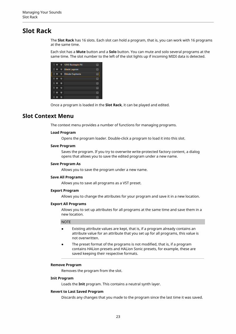
Slot RackThe Slot Rack has 16 slots. Each slot can hold a program, that is, you can work with 16 programsat the same time.
Each slot has a Mute button and a Solo button. You can mute and solo several programs at thesame time. The slot number to the left of the slot lights up if incoming MIDI data is detected.
Once a program is loaded in the Slot Rack, it can be played and edited.
Slot Context MenuThe context menu provides a number of functions for managing programs.
Load ProgramOpens the program loader. Double-click a program to load it into this slot.
Save ProgramSaves the program. If you try to overwrite write-protected factory content, a dialogopens that allows you to save the edited program under a new name.
Save Program AsAllows you to save the program under a new name.
Save All ProgramsAllows you to save all programs as a VST preset.
Export ProgramAllows you to change the attributes for your program and save it in a new location.
Export All ProgramsAllows you to set up attributes for all programs at the same time and save them in anew location.
NOTE
● Existing attribute values are kept, that is, if a program already contains anattribute value for an attribute that you set up for all programs, this value isnot overwritten.
● The preset format of the programs is not modified, that is, if a programcontains HALion presets and HALion Sonic presets, for example, these aresaved keeping their respective formats.
Remove ProgramRemoves the program from the slot.
Init ProgramLoads the Init program. This contains a neutral synth layer.
Revert to Last Saved ProgramDiscards any changes that you made to the program since the last time it was saved.
23
Managing Your SoundsManaging and Loading Files
Cut ProgramCopies the program and removes it from the slot.
Copy ProgramCopies the program.
Paste ProgramPastes the copied program into the slot. If the slot already contains a program, it isreplaced.
Rename ProgramAllows you to rename the program.
Reset SlotResets the slot to the default values.
Reset All SlotsResets all slots to the default values.
NOTE
You can also cut, copy, and paste programs from one plug-in instance to another.
Managing and Loading FilesYou can use the MediaBay to manage, navigate to, and load different file types.
Managing MultisMultis can load multiple sounds or programs and combine them.
You can use multis to layer several programs or to create split sounds by setting severalprograms to the same MIDI input channel, for example. However, the most common usage is tocreate sound sets with different instruments set to individual MIDI channels.
A multi-program contains all plug-in parameters. If you use HALion Sonic SE as a plug-in in aSteinberg DAW, these multis are listed in the Preset Management pop-up menu of the hostapplication. You can drag multis and programs from the MediaBay to a slot in HALion Sonic SE.
If you use HALion Sonic SE as a plug-in in a different host application, you can use the presetfunctionality from the host application or the multi management features provided by HALionSonic SE.
Loading MultisYou can load multis in the following ways:
● Open the MediaBay and double-click a multi or drag a multi onto the multi slot.
● Click the Load Multi-Program button in the multi slot to open the Load Multi-Programdialog, select a multi, and click OK.
Renaming Multis
PROCEDURE
● To rename a multi, click in the name field, enter a new name, and press Return.
24
Managing Your SoundsManaging and Loading Files
Removing Multis● To remove all programs of the current multi, click the Remove All Programs button on the
toolbar of the multi program rack.
Clearing the Plug-In Instance● To reset the entire plug-in instance to an empty state, right-click the multi loader and
select Clear Plug-in Instance from the context menu.
Saving Multis
PROCEDURE
1. Click the Save Multi-Program button.
2. Enter the name of the multi.
3. Assign any attributes that you want to use and click OK.If the entered name already exists, a message opens. Click Make Unique Name to add anumber suffix to the name of the new multi.
Saving a Multi as Default● To specify a default multi to be loaded with HALion Sonic SE, use the Save as Default
command on the context menu for the multi loader.
Creating Subfolders for User-Defined MultisYou can create subfolders inside the user preset folder to organize presets.
● To create a new folder, click the Create New Folder icon at the top left of the Save Multi-Program dialog.
Navigating Through the Folder HierarchyYou can move through the folder hierarchy using the three navigation buttons at the top left ofthe dialog.
These buttons allow you to navigate to the previous or next browse location, or browse thecontaining folder.
Editing AttributesYou can edit the attribute values that are assigned to the preset.
PROCEDURE
1. Open the Save Multi-Program dialog and navigate to the New Preset Tags section.
2. To edit an attribute, click on a value field and enter the new name or value.
3. Click OK to save the preset.
Managing Files via the MediaBayThe MediaBay functionality can be found on the Load page.
● To adjust the size of the two sections, drag the divider at the top of the results list.
25

Managing Your SoundsManaging and Loading Files
Browsing for FilesThe Load page allows you to browse for and load files. You can restrict the amount of files thatare searched by filtering the results list or entering a search text.
PROCEDURE
1. On the Select Content Set menu, select the content set from which you want to load aprogram or layer. To browse the entire content, select All.
2. On the toolbar of the results list, specify whether you want to browse through theavailable programs or layers .
3. Optional: In the upper section of the page, click on an attribute to display only those filescontaining the attribute, for example, percussion, or a specific musical style, etc.You can activate several attribute filters simultaneously.
4. If you are looking for a specific file, enter its name in the text search field on the toolbar.You can also enter text that is part of the file name or the file attributes in the search field.
5. In the results list, double-click a file to load it in the selected slot.
6. Play a note on your keyboard or use the internal keyboard to listen to the selected file.If the file is not what you were looking for, step through the files in the results list andlisten to them until you found the file that you want to use.
Filtering the Results
Category Filter
You can filter the results list based on up to four filter criteria using the configurable attributecolumns. The standard attributes are Category, Sub Category, Style, and Character.
Only the files that match the set filter are displayed in the results list.
● To set up the filter, click on specific values in the columns.
● To select different filter criteria, click the column header and select a different attributefrom the submenu.
Content Set Filter
Use the Select Content Set pop-up menu to search a specific content set. By default, the searchis performed in all installed content sets.
Results ListThe results list shows all files that have been found according to the category filter.
Text SearchIn the text search field on the results list toolbar, you can enter text contained in thename or any of the attributes of a preset that you are looking for. The results list isupdated immediately and the category search section above shows all categoriesthat contain presets matching the text search.To reset the text-based result filter, click Clear Search Text next to the search field.
View FiltersThe toolbar has three filter buttons that allow you to define which preset types to
display: multis , programs , or layers . In the results list, the correspondingicon is shown to the left of the preset name.
26

Managing Your SoundsManaging and Loading Files
Rating FilterYou can limit the results list according to the rating of the presets. Use the ratingslider to define the minimum rating.
Content Filters
The content filter buttons allow you to define whether to show the entire content ,
only the factory content , or only your user content .
Rescan DiskRescans the disk for files that match the search criteria. Click this button if you addedor removed files on your hard disk, for example.
Set Up Result ColumnsAllows you to select which attribute columns to display on the toolbar.
Results CounterDisplays the number of files that match the filter criteria. To stop an active scanningprocess, click in the value field.
RELATED LINKSConfiguring the Results List on page 27
Configuring the Results List
● To configure which attributes are shown in the results list, click Set up Result Columnsin the upper right corner of the results list and activate the corresponding entries. Newattributes are added at the right of the list.
● To reorder the columns in the results list, drag the column headers to another position.
● To change the sorting of the list entries, click the column header. The triangle in thecolumn header shows the sorting direction.
Assigning General MIDI Program Change Numbers to Sounds
PROCEDURE
1. In the MediaBay, click Set up Result Columns on the title bar of the lower section.
2. Select Musical > GM Sound.
3. Select the sound to which you want to apply the GM program change number.
4. In the GM Sound column for the sound, select the General MIDI program change numberthat you want to use.
27
Managing Your SoundsManaging and Loading Files
You can assign the same GM Sound program number several times. If a program numberis used more than once, the Rating attribute can be used to decide which program to load.
RESULTNow, you can use MIDI program change messages to load the assigned sounds into the slot ofthe corresponding MIDI channel.
NOTE
Slot 10 ignores any program change messages and keeps the loaded drum set.
Loading Programs into SlotsTo load a program into one of the slots of the Slot Rack, you have the following possibilities:
● Select the slot into which you want to load the program, and double-click the program inthe results list.
● Drag a program from the results list to an empty space in the Slot Rack to create a newslot.If you drag it to an existing slot, the current program is replaced.
● Right-click the program and select Load Program into selected Slot from the contextmenu.
28

Editing Programs
You can make settings for the programs and their layers on the Edit page.
The factory content that comes with the Steinberg DAW features a macro page for each layer in aprogram. This page allows you to adjust the most important parameters. If a program consists ofmultiple layers, you can access the different layer pages by clicking the layer buttons (L1, L2, L3,L4) in the title bar of the macro page.
NOTE
Content that uses one of the included instruments features an instrument-specific macro page.
RELATED LINKSIncluded Instruments on page 32
Editing the Factory ContentWhich content is available for HALion Sonic SE depends on which Steinberg DAW you are using.However, even though the available programs and layers may differ between versions, they usethe same macro page.
The macro page is divided into the following sections: Voice/Pitch, Filter and Amplifier.
In the top right section of the macro page, information on the content is shown.
Voice/Pitch Section
This section gives you access to the tuning parameters.
OctaveAdjusts the pitch in octave steps.
CoarseAdjusts the pitch in semitone steps.
FineAllows you to fine-tune the pitch in cent steps.
29
Editing ProgramsEditing the Factory Content
Pitchbend Up/Pitchbend DownDetermines the range for the modulation that is applied when you move thepitchbend wheel.
PolyphonyIf Mono mode is deactivated, you can use this parameter to specify how many notescan be played simultaneously.
MonoActivates monophonic playback.
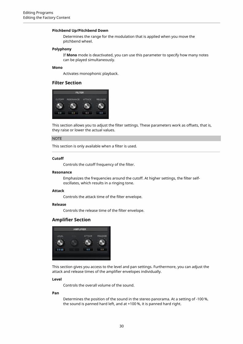
Filter Section
This section allows you to adjust the filter settings. These parameters work as offsets, that is,they raise or lower the actual values.
NOTE
This section is only available when a filter is used.
CutoffControls the cutoff frequency of the filter.
ResonanceEmphasizes the frequencies around the cutoff. At higher settings, the filter self-oscillates, which results in a ringing tone.
AttackControls the attack time of the filter envelope.
ReleaseControls the release time of the filter envelope.
Amplifier Section
This section gives you access to the level and pan settings. Furthermore, you can adjust theattack and release times of the amplifier envelopes individually.
LevelControls the overall volume of the sound.
PanDetermines the position of the sound in the stereo panorama. At a setting of -100 %,the sound is panned hard left, and at +100 %, it is panned hard right.
30

Editing ProgramsEditing the Factory Content
AttackControls the attack time of the amplifier envelope.
DecayControls the decay time of the amplifier envelope.
31
Included Instruments
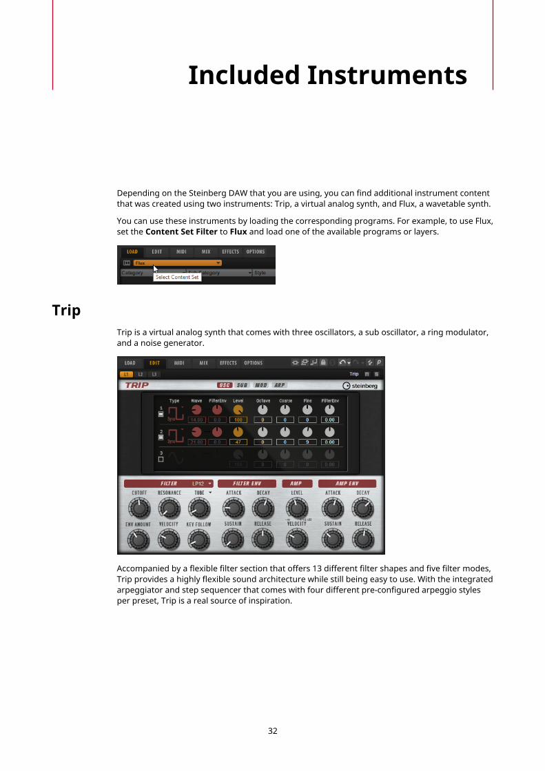
Depending on the Steinberg DAW that you are using, you can find additional instrument contentthat was created using two instruments: Trip, a virtual analog synth, and Flux, a wavetable synth.
You can use these instruments by loading the corresponding programs. For example, to use Flux,set the Content Set Filter to Flux and load one of the available programs or layers.
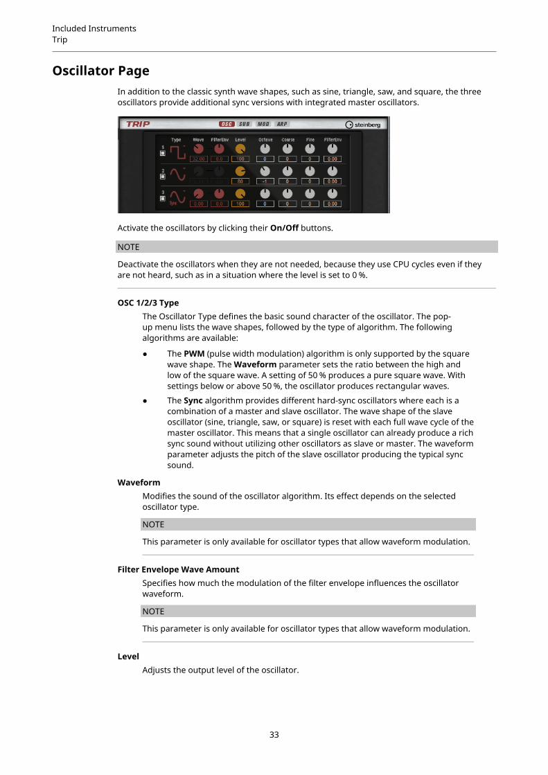
TripTrip is a virtual analog synth that comes with three oscillators, a sub oscillator, a ring modulator,and a noise generator.
Accompanied by a flexible filter section that offers 13 different filter shapes and five filter modes,Trip provides a highly flexible sound architecture while still being easy to use. With the integratedarpeggiator and step sequencer that comes with four different pre-configured arpeggio stylesper preset, Trip is a real source of inspiration.
32
Included InstrumentsTrip
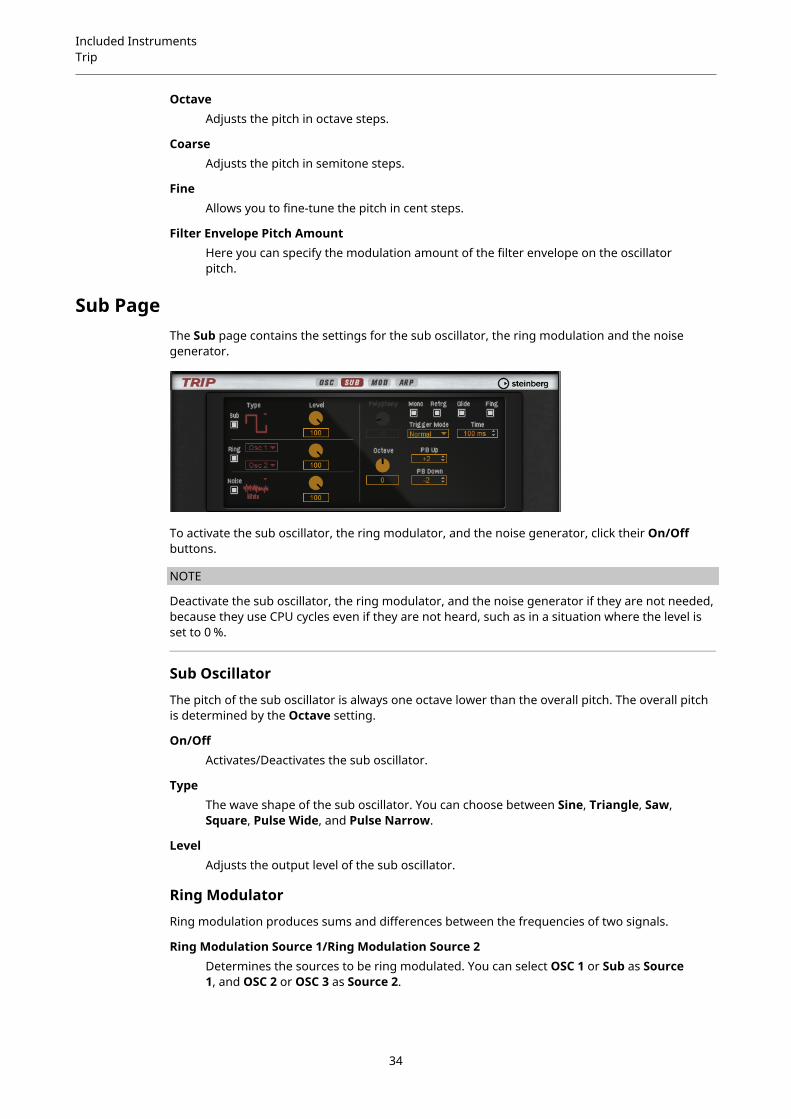
Oscillator PageIn addition to the classic synth wave shapes, such as sine, triangle, saw, and square, the threeoscillators provide additional sync versions with integrated master oscillators.
Activate the oscillators by clicking their On/Off buttons.
NOTE
Deactivate the oscillators when they are not needed, because they use CPU cycles even if theyare not heard, such as in a situation where the level is set to 0 %.
OSC 1/2/3 TypeThe Oscillator Type defines the basic sound character of the oscillator. The pop-up menu lists the wave shapes, followed by the type of algorithm. The followingalgorithms are available:
● The PWM (pulse width modulation) algorithm is only supported by the squarewave shape. The Waveform parameter sets the ratio between the high andlow of the square wave. A setting of 50 % produces a pure square wave. Withsettings below or above 50 %, the oscillator produces rectangular waves.
● The Sync algorithm provides different hard-sync oscillators where each is acombination of a master and slave oscillator. The wave shape of the slaveoscillator (sine, triangle, saw, or square) is reset with each full wave cycle of themaster oscillator. This means that a single oscillator can already produce a richsync sound without utilizing other oscillators as slave or master. The waveformparameter adjusts the pitch of the slave oscillator producing the typical syncsound.
WaveformModifies the sound of the oscillator algorithm. Its effect depends on the selectedoscillator type.
NOTE
This parameter is only available for oscillator types that allow waveform modulation.
Filter Envelope Wave AmountSpecifies how much the modulation of the filter envelope influences the oscillatorwaveform.
NOTE
This parameter is only available for oscillator types that allow waveform modulation.
LevelAdjusts the output level of the oscillator.
33
Included InstrumentsTrip
OctaveAdjusts the pitch in octave steps.
CoarseAdjusts the pitch in semitone steps.
FineAllows you to fine-tune the pitch in cent steps.
Filter Envelope Pitch AmountHere you can specify the modulation amount of the filter envelope on the oscillatorpitch.
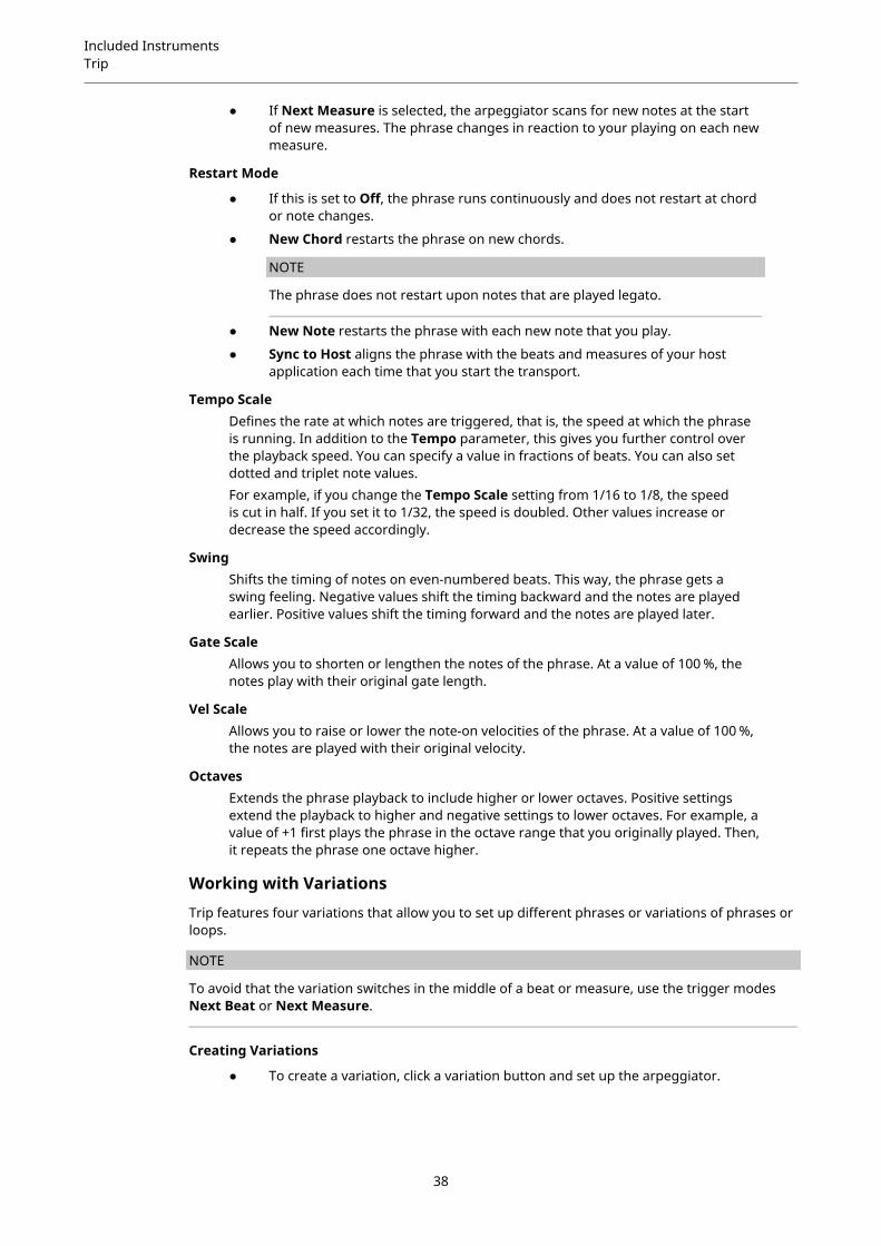
Sub PageThe Sub page contains the settings for the sub oscillator, the ring modulation and the noisegenerator.
To activate the sub oscillator, the ring modulator, and the noise generator, click their On/Offbuttons.
NOTE
Deactivate the sub oscillator, the ring modulator, and the noise generator if they are not needed,because they use CPU cycles even if they are not heard, such as in a situation where the level isset to 0 %.
Sub Oscillator
The pitch of the sub oscillator is always one octave lower than the overall pitch. The overall pitchis determined by the Octave setting.
On/OffActivates/Deactivates the sub oscillator.
TypeThe wave shape of the sub oscillator. You can choose between Sine, Triangle, Saw,Square, Pulse Wide, and Pulse Narrow.
LevelAdjusts the output level of the sub oscillator.
Ring Modulator
Ring modulation produces sums and differences between the frequencies of two signals.
Ring Modulation Source 1/Ring Modulation Source 2Determines the sources to be ring modulated. You can select OSC 1 or Sub as Source1, and OSC 2 or OSC 3 as Source 2.
34

Included InstrumentsTrip
NOTE
Make sure that the corresponding oscillators are activated when you select them.Otherwise, no sound is heard.
Ring Modulation LevelAdjusts the output level of the ring modulation.
Noise Generator
Noise TypeThe sound color of the noise. You can choose between standard and band-passfiltered (BPF) versions of white and pink noise.
Noise LevelAdjusts the output level of the noise generator.
Trigger and Pitch Section
PolyphonyIf Mono mode is deactivated, you can use this parameter to specify how many notescan be played simultaneously.
MonoActivates monophonic playback.
RetriggerThis option is only available in Mono mode. If Retrigger is activated, a note thatwas stolen by another note is retriggered if you still hold the stolen note when yourelease the new one.This way, you can play trills by holding one note and quickly and repeatedly pressingand releasing another note, for example.
Trigger ModeDefines the trigger behavior for new notes. The following settings are available:
● In Normal mode, a new note is triggered when the previous note is stolen.
● In Resume mode, the envelope is retriggered, but resumes at the level of thestolen note. The pitch is set to the new note.
● In Legato mode, the envelopes keep playing and the pitch is set to the newnote.
GlideAllows you to bend the pitch between notes that follow each other. You achieve thebest results in Mono mode.
Glide TimeSets the glide time, that is, the time it takes to bend the pitch from one note to thenext.
35

Included InstrumentsTrip
FingeredActivate this parameter to glide the pitch only between notes that are played legato.
OctaveAdjusts the pitch in octave steps.
Pitchbend Up/Pitchbend DownDetermines the range for the modulation that is applied when you move thepitchbend wheel.
Mod PageThe Mod page contains the LFO settings in the upper section and the mod wheel, or vibrato,settings in the lower section.
LFO Settings
FreqControls the frequency of the modulation, that is, the speed of the LFO.
SyncIf Sync is activated, the frequency is set in fractions of beats.
PitchControls the modulation depth of the pitch modulation.
CutoffControls the modulation depth of the filter cutoff modulation.
PitchControls the modulation depth of the pitch modulation.
CutoffControls the modulation depth of the filter cutoff modulation.
Osc1/2/3 WaveThese parameters control the modulation depth of the waveform modulation of thethree main oscillators.
NOTE
These controls are only available if the selected oscillator type supports waveformmodulation.
Vibrato Parameters
Vib FreqControls the frequency of the second LFO that is used for pitch modulation (vibrato).
36

Included InstrumentsTrip
Vib DepthControls the depth of the pitch modulation (vibrato).
CutoffControls the influence of the mod wheel on the filter cutoff.
Osc1/2/3 WaveThese parameters control the influence of the mod wheel on the waveform of thethree main oscillators.
NOTE
These controls are only available if the selected oscillator type supports waveformmodulation.
Arp PageThis page contains the integrated arpeggiator.
VariationsClick the variation buttons to switch between the available variations.
LoopIf this option is activated, the phrase plays in a loop.
HoldAllows you to prevent the phrase from stopping or changing when the keys arereleased.
● If Off is selected, the phrase changes as soon as you release a key. The phrasestops immediately when you release all keys.
● If On is selected, the phrase plays to the end, even if the keys are released. IfLoop is activated, the phrase repeats continuously.
● If Gated is selected, the phrase starts to play when the first key is played. Itplays silently in the background, even if the keys are released, and resumesplayback at the current position when you press any of the keys again. Thisway, you can gate the playback of the phrase.
Trigger ModeDetermines at which moment the arpeggiator scans for new notes that you play onthe keyboard.
● If Immediately is selected, the arpeggiator scans for new notes all the time.The phrase changes immediately in reaction to your playing.
● If Next Beat is selected, the arpeggiator scans for new notes at every newbeat. The phrase changes in reaction to your playing on each new beat.
37
Included InstrumentsTrip
● If Next Measure is selected, the arpeggiator scans for new notes at the startof new measures. The phrase changes in reaction to your playing on each newmeasure.
Restart Mode
● If this is set to Off, the phrase runs continuously and does not restart at chordor note changes.
● New Chord restarts the phrase on new chords.
NOTE
The phrase does not restart upon notes that are played legato.
● New Note restarts the phrase with each new note that you play.
● Sync to Host aligns the phrase with the beats and measures of your hostapplication each time that you start the transport.
Tempo ScaleDefines the rate at which notes are triggered, that is, the speed at which the phraseis running. In addition to the Tempo parameter, this gives you further control overthe playback speed. You can specify a value in fractions of beats. You can also setdotted and triplet note values.For example, if you change the Tempo Scale setting from 1/16 to 1/8, the speedis cut in half. If you set it to 1/32, the speed is doubled. Other values increase ordecrease the speed accordingly.
SwingShifts the timing of notes on even-numbered beats. This way, the phrase gets aswing feeling. Negative values shift the timing backward and the notes are playedearlier. Positive values shift the timing forward and the notes are played later.
Gate ScaleAllows you to shorten or lengthen the notes of the phrase. At a value of 100 %, thenotes play with their original gate length.
Vel ScaleAllows you to raise or lower the note-on velocities of the phrase. At a value of 100 %,the notes are played with their original velocity.
OctavesExtends the phrase playback to include higher or lower octaves. Positive settingsextend the playback to higher and negative settings to lower octaves. For example, avalue of +1 first plays the phrase in the octave range that you originally played. Then,it repeats the phrase one octave higher.
Working with Variations
Trip features four variations that allow you to set up different phrases or variations of phrases orloops.
NOTE
To avoid that the variation switches in the middle of a beat or measure, use the trigger modesNext Beat or Next Measure.
Creating Variations
● To create a variation, click a variation button and set up the arpeggiator.
38
Included InstrumentsTrip
The variation is instantly modified and can be recalled by clicking the Variationbutton.
Copying VariationsYou can copy variation settings between the variation buttons using thecorresponding commands on the context menu.
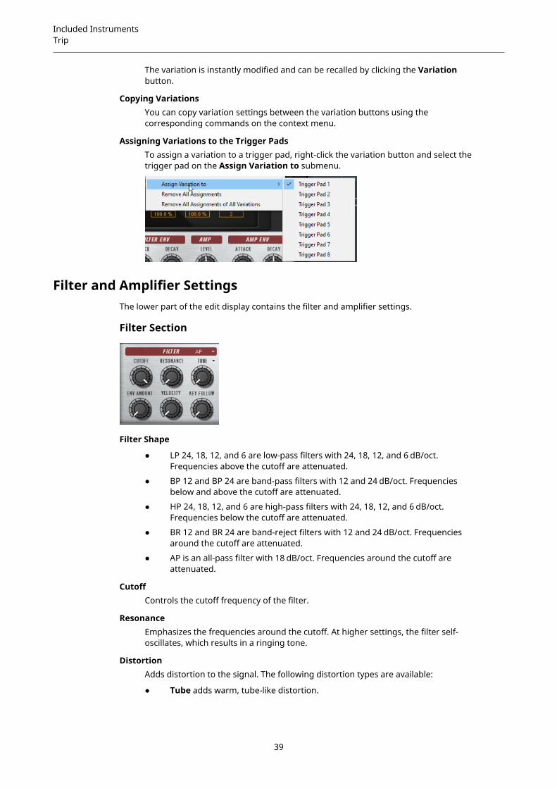
Assigning Variations to the Trigger PadsTo assign a variation to a trigger pad, right-click the variation button and select thetrigger pad on the Assign Variation to submenu.
Filter and Amplifier SettingsThe lower part of the edit display contains the filter and amplifier settings.
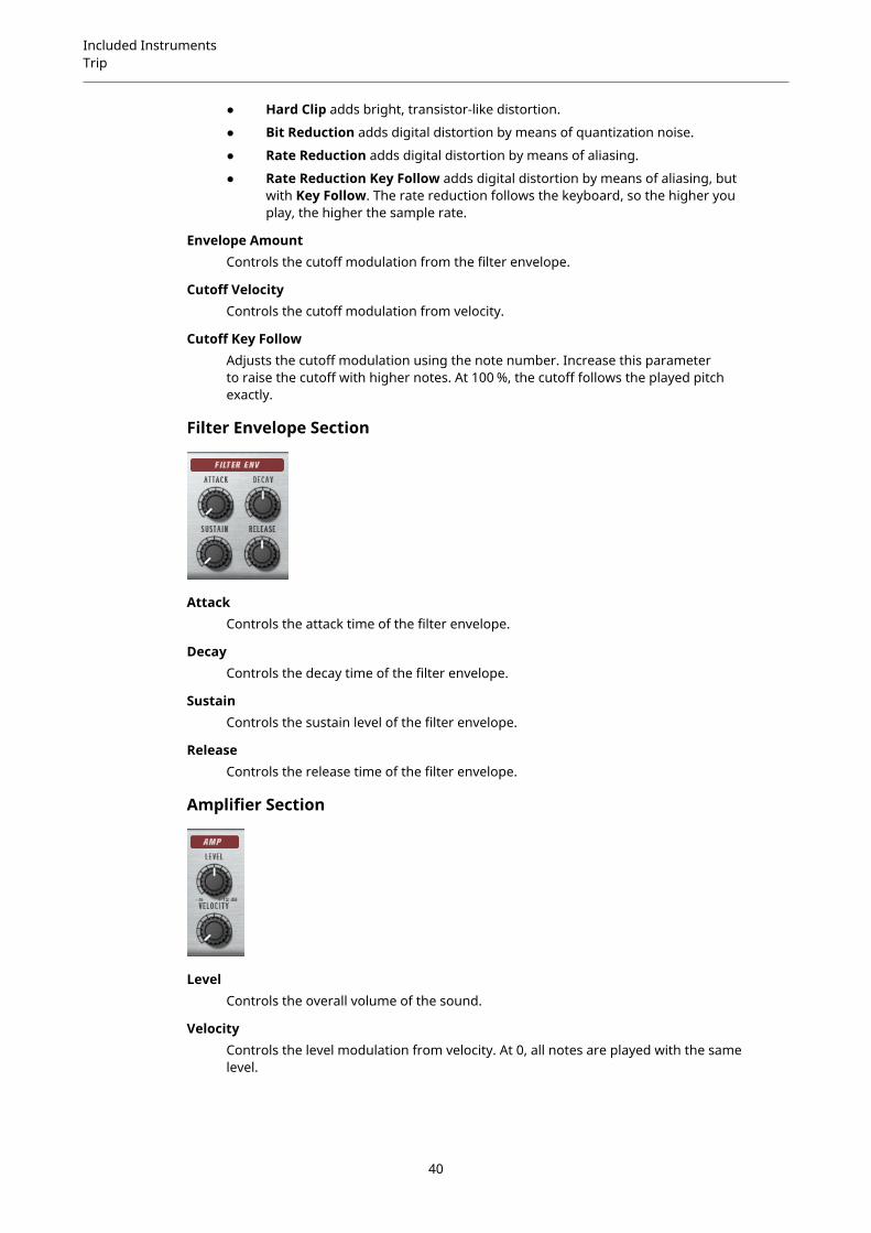
Filter Section
Filter Shape
● LP 24, 18, 12, and 6 are low-pass filters with 24, 18, 12, and 6 dB/oct.Frequencies above the cutoff are attenuated.
● BP 12 and BP 24 are band-pass filters with 12 and 24 dB/oct. Frequenciesbelow and above the cutoff are attenuated.
● HP 24, 18, 12, and 6 are high-pass filters with 24, 18, 12, and 6 dB/oct.Frequencies below the cutoff are attenuated.
● BR 12 and BR 24 are band-reject filters with 12 and 24 dB/oct. Frequenciesaround the cutoff are attenuated.
● AP is an all-pass filter with 18 dB/oct. Frequencies around the cutoff areattenuated.
CutoffControls the cutoff frequency of the filter.
ResonanceEmphasizes the frequencies around the cutoff. At higher settings, the filter self-oscillates, which results in a ringing tone.
DistortionAdds distortion to the signal. The following distortion types are available:
● Tube adds warm, tube-like distortion.
39
Included InstrumentsTrip
● Hard Clip adds bright, transistor-like distortion.
● Bit Reduction adds digital distortion by means of quantization noise.
● Rate Reduction adds digital distortion by means of aliasing.
● Rate Reduction Key Follow adds digital distortion by means of aliasing, butwith Key Follow. The rate reduction follows the keyboard, so the higher youplay, the higher the sample rate.
Envelope AmountControls the cutoff modulation from the filter envelope.
Cutoff VelocityControls the cutoff modulation from velocity.
Cutoff Key FollowAdjusts the cutoff modulation using the note number. Increase this parameterto raise the cutoff with higher notes. At 100 %, the cutoff follows the played pitchexactly.
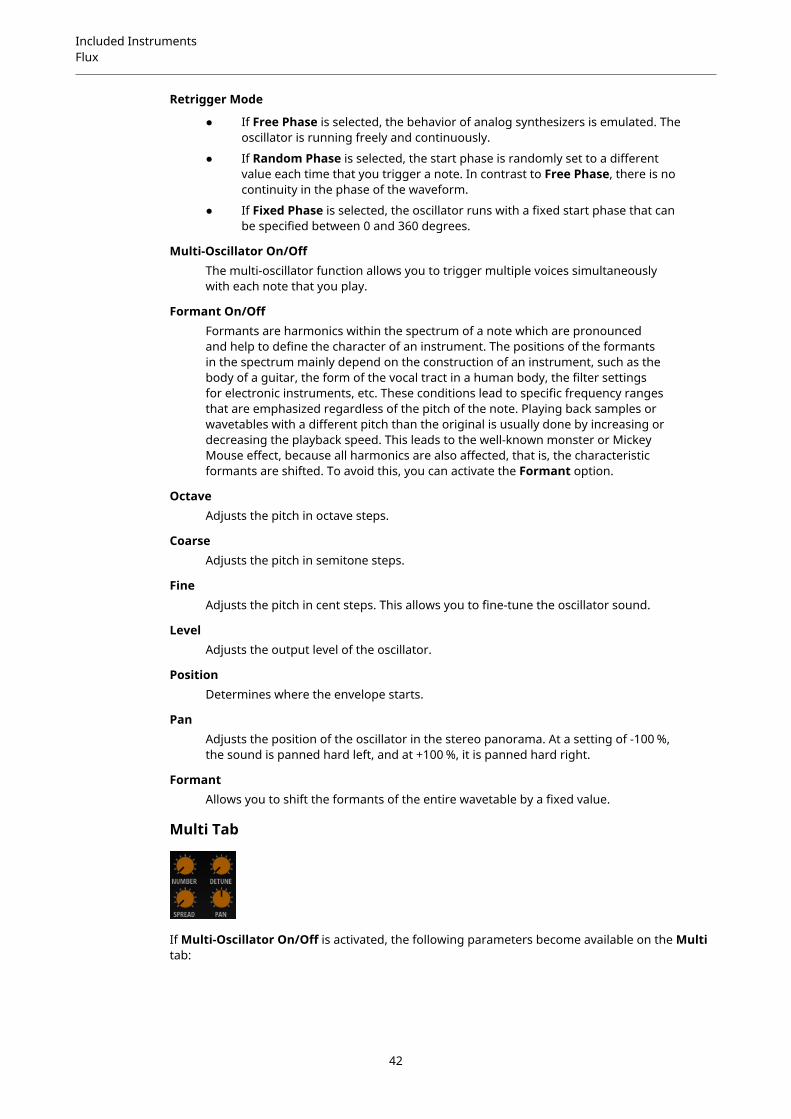
Filter Envelope Section
AttackControls the attack time of the filter envelope.
DecayControls the decay time of the filter envelope.
SustainControls the sustain level of the filter envelope.
ReleaseControls the release time of the filter envelope.
Amplifier Section
LevelControls the overall volume of the sound.
VelocityControls the level modulation from velocity. At 0, all notes are played with the samelevel.
40

Included InstrumentsFlux
Amplifier Envelope Section
AttackControls the attack time of the amplifier envelope.
DecayControls the decay time of the amplifier envelope.
SustainControls the sustain level of the amplifier envelope.
ReleaseControls the release time of the amplifier envelope.
FluxFlux is a wavetable synth that uses HALion’s wavetable synthesis. It provides two main wavetableoscillators, a classical sub oscillator, and a flexible noise generator.
You can change the waveform of the included wavetables during playback, either with thePosition control or by modulating the wavetable position with a variety of modulation sources,such as LFOs and envelopes, to create your own sweeping sounds quickly and easily.
In addition to the wavetable oscillators, Flux also provides a filter section with 24 different filtershapes which enables you to shape the sound even further.
Oscillator PageThe Osc page contains the settings for the two main oscillators.
● To activate/deactivate an oscillator, click the corresponding On/Off button on the right ofthe Osc button.
Select WavetableThis pop-up menu allows you to select one of the included wavetables for thewavetable oscillator.
41
Included InstrumentsFlux
Retrigger Mode
● If Free Phase is selected, the behavior of analog synthesizers is emulated. Theoscillator is running freely and continuously.
● If Random Phase is selected, the start phase is randomly set to a differentvalue each time that you trigger a note. In contrast to Free Phase, there is nocontinuity in the phase of the waveform.
● If Fixed Phase is selected, the oscillator runs with a fixed start phase that canbe specified between 0 and 360 degrees.
Multi-Oscillator On/OffThe multi-oscillator function allows you to trigger multiple voices simultaneouslywith each note that you play.
Formant On/OffFormants are harmonics within the spectrum of a note which are pronouncedand help to define the character of an instrument. The positions of the formantsin the spectrum mainly depend on the construction of an instrument, such as thebody of a guitar, the form of the vocal tract in a human body, the filter settingsfor electronic instruments, etc. These conditions lead to specific frequency rangesthat are emphasized regardless of the pitch of the note. Playing back samples orwavetables with a different pitch than the original is usually done by increasing ordecreasing the playback speed. This leads to the well-known monster or MickeyMouse effect, because all harmonics are also affected, that is, the characteristicformants are shifted. To avoid this, you can activate the Formant option.
OctaveAdjusts the pitch in octave steps.
CoarseAdjusts the pitch in semitone steps.
FineAdjusts the pitch in cent steps. This allows you to fine-tune the oscillator sound.
LevelAdjusts the output level of the oscillator.
PositionDetermines where the envelope starts.
PanAdjusts the position of the oscillator in the stereo panorama. At a setting of -100 %,the sound is panned hard left, and at +100 %, it is panned hard right.
FormantAllows you to shift the formants of the entire wavetable by a fixed value.
Multi Tab
If Multi-Oscillator On/Off is activated, the following parameters become available on the Multitab:
42
Included InstrumentsFlux
● Number determines the number of oscillators that play back simultaneously. You can alsoset fractions of numbers. For example, with a setting of 2.5, you hear two oscillators at fulllevel and a third one at half level.
● Detune detunes the oscillators.
● Pan narrows or widens the stereo panorama. With a setting of 0 %, you create a monosignal and with 100 %, you create a stereo signal.
● Spread distributes the oscillators so that each oscillator plays from a different position inthe wavetable.
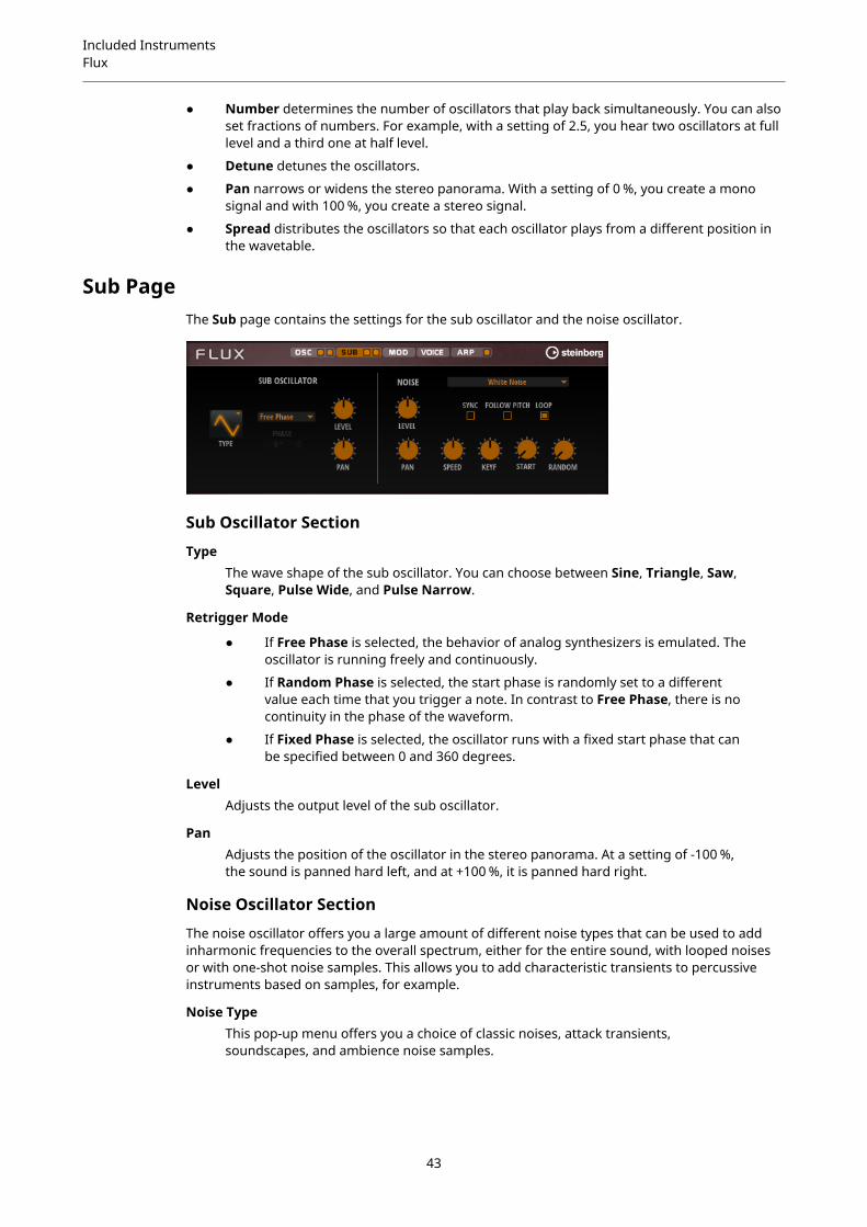
Sub PageThe Sub page contains the settings for the sub oscillator and the noise oscillator.
Sub Oscillator Section
TypeThe wave shape of the sub oscillator. You can choose between Sine, Triangle, Saw,Square, Pulse Wide, and Pulse Narrow.
Retrigger Mode
● If Free Phase is selected, the behavior of analog synthesizers is emulated. Theoscillator is running freely and continuously.
● If Random Phase is selected, the start phase is randomly set to a differentvalue each time that you trigger a note. In contrast to Free Phase, there is nocontinuity in the phase of the waveform.
● If Fixed Phase is selected, the oscillator runs with a fixed start phase that canbe specified between 0 and 360 degrees.
LevelAdjusts the output level of the sub oscillator.
PanAdjusts the position of the oscillator in the stereo panorama. At a setting of -100 %,the sound is panned hard left, and at +100 %, it is panned hard right.
Noise Oscillator Section
The noise oscillator offers you a large amount of different noise types that can be used to addinharmonic frequencies to the overall spectrum, either for the entire sound, with looped noisesor with one-shot noise samples. This allows you to add characteristic transients to percussiveinstruments based on samples, for example.
Noise TypeThis pop-up menu offers you a choice of classic noises, attack transients,soundscapes, and ambience noise samples.
43

Included InstrumentsFlux
LevelAdjusts the output level of the Noise section.
SyncActivate Sync to synchronize the speed of the noise oscillator to the host tempo. Thisis particularly useful for rhythmic noises that are based on a tempo of 120 BPM.
PanDetermines the position of the noise in the stereo panorama. At a setting of -100 %,the sound is panned hard left, and at +100 %, it is panned hard right.
Follow PitchIf Follow Pitch is activated, zone pitch settings like Octave, Coarse, and Fine, as wellas modulations like Glide, Pitchbend, or other pitch modulations, affect the durationlength. A higher sample pitch leads to a shorter duration.If Follow Pitch is deactivated, the duration is independent of the zone pitch anddetermined by the Duration settings.
LoopActivate this button to play the noise sample in a loop.If this button is not activated, the sample is played once.
SpeedAdjusts the playback speed of the noise sample. A setting of 800.0 % equals anincrease of three octaves in pitch.
Speed Key FollowAllows you to adjust the speed modulation by MIDI note number. At a setting of+100 %, the speed doubles per octave.
StartAdjusts the start of the noise sample. With a value of 50 %, playback starts in themiddle of the sample.
Random StartSelects a random playback start within a specific range around the current position.At a setting of 100 %, the playback position jumps to a random position between thespecified Start value and the end of the noise sample.
Mod PageThe Mod page contains the modulation matrix.
The modulation matrix offers you up to 16 freely assignable modulations, each with a source, amodifier, and a destination with adjustable depth. The polarity of each source and each modifiercan be switched between unipolar and bipolar.
44
Included InstrumentsFlux
Creating ModulationsYou create modulations by selecting a source, a modifier, and a destination from the pop-upmenus in the modulation matrix.
PROCEDURE
1. Click the modulation Source field and select the modulation source.
2. Optional: Click in the modulation Modifier field and select the parameter that you want touse to modify the modulation.This modifier is used to scale the output of the modulation source.
3. Optional: Specify whether you want the Source and Modifier parameters to be unipolar orbipolar.
4. Set the modulation intensity with the Depth parameter.
5. Click in the modulation Destination field and select the parameter that you want tomodulate.
Modulation Matrix Parameters
Modulation Sources and Modulation Modifiers
The following options are available as modulation sources and as modulation modifiers.
LFO A/BThe LFOs A and B produce cyclic modulation signals.
Amp EnvelopeThe amplifier envelope. The shape of the envelope determines the modulationsignal.
Filter EnvelopeThe filter envelope. The shape of the envelope determines the modulation signal.
Env 3A freely assignable envelope. It is suitable for pan or pitch modulation, for example.
Key FollowThis produces an exponential modulation signal derived from the MIDI note number.Exponential means this source works with destinations such as Pitch or Cutoff.
Note-on VelocityNote-on velocity can be used as modulation signal.
Note-on Vel SquaredThe squared version of Note-on Velocity. The harder you press the key, the higherthe modulation values.
PitchbendThe position of the pitchbend wheel can be used as modulation signal.
Modulation WheelThe position of the modulation wheel can be used as modulation signal.
AftertouchAftertouch can be used as modulation signal. Some MIDI keyboards cannot sendaftertouch messages. However, most sequencer software is able to produce suchmessages.
45
Included InstrumentsFlux
Arp Controller 1–3The 3 controllers available on this submenu correspond to the three controller laneson the Arp page.
Bus 1–8Modulations that are sent to one of the eight busses can be reused as sources. Thisway, you can combine several modulations to produce more complex signals.
Unipolar vs. Bipolar Sources
The polarity of a modulation source specifies the value range that it produces. Unipolar sourcesmodulate between 0 and +1. Bipolar sources modulate between -1 and +1.
● To change the polarity of a modulation source or modifier from unipolar to bipolar,activate its Bipolar button.
Modulation Destinations
PitchModulates the pitch. For example, assign one of the LFOs to create a vibrato effect. IfPitch is selected, the modulation depth is set in semitones.
CutoffModulates the filter cutoff.
ResonanceModulates the filter resonance. Resonance changes the character of the filter.For example, to accent the filter the harder you hit a key, assign Velocity toResonance.
DistortionModulates the filter distortion.
LevelThis modulation adds to the level setting. It can be used to create level offsets usingthe mod wheel, for example.
VolumeModulates the gain. The volume modulation multiplies with the level.
PanModulates the position of the sound in the panorama.
WT 1/2 PitchModulates the Pitch parameter of the corresponding wavetable oscillator.
WT 1/2 LevelModulates the Level parameter of the corresponding wavetable oscillator.
WT 1/2 PanModulates the Pan parameter of the corresponding wavetable oscillator.
WT 1/2 Multi DetuneModulates the multi-oscillator Detune parameter of the corresponding wavetableoscillator.
WT 1/2 Multi PanModulates the multi-oscillator Pan parameter of the corresponding wavetableoscillator.
46

Included InstrumentsFlux
WT 1/2 Multi SpreadModulates the multi-oscillator Spread parameter of the corresponding wavetableoscillator.
WT 1/2 Multi VoicesModulates the multi-oscillator Voices parameter of the corresponding oscillator.
WT 1/2 PositionModulates the Position parameter of the corresponding wavetable oscillator.
WT 1/2 Formant ShiftModulates the Formant Shift parameter of the corresponding wavetable oscillator.
WT Sub PitchModulates the Pitch parameter of the wavetable sub oscillator.
WT Sub LevelModulates the Level parameter of the wavetable sub oscillator.
WT Sub PanModulates the Pan parameter of the wavetable sub oscillator.
WT Noise SpeedModulates the Speed parameter of the wavetable noise oscillator.
WT Noise LevelModulates the Level parameter of the wavetable noise oscillator.
WT Noise PanModulates the Pan parameter of the wavetable noise oscillator.
Amp Env AttackModulates the attack time of the amplitude envelope. This modulation destinationcannot be modulated continuously. The time is updated only when the segmentstarts.
Amp Env DecayModulates the decay time of the amplitude envelope. This modulation destinationcannot be modulated continuously. The time is updated only when the segmentstarts.
Amp Env SustainModulates the sustain level of the amplitude envelope. This modulation destinationcannot be modulated continuously. The level is updated only when the segmentstarts.
Amp Env ReleaseModulates the release time of the amplitude envelope. This modulation destinationcannot be modulated continuously. The time is updated only when the segmentstarts.
Filter Env AttackModulates the attack time of the filter envelope. This modulation destination cannotbe modulated continuously. The time is updated only when the segment starts.
Filter Env DecayModulates the decay time of the filter envelope. This modulation destination cannotbe modulated continuously. The time is updated only when the segment starts.
47
Included InstrumentsFlux
Filter Env SustainModulates the sustain level of the filter envelope. This modulation destination cannotbe modulated continuously. The level is updated only when the segment starts.
Filter Env ReleaseModulates the release time of the filter envelope. This modulation destination cannotbe modulated continuously. The time is updated only when the segment starts.
Env 3 Start LevelModulates the start level of the user-definable envelope 3, that is, the level of thefirst envelope node. This modulation destination cannot be modulated continuously.The level is updated only when the segment starts.
Env 3 AttackModulates the attack time of the user-definable envelope 3. This modulationdestination cannot be modulated continuously. The time is updated only when thesegment starts.
Env 3 Attack LevelModulates the attack level of the user-definable envelope 3, that is, the level ofthe second envelope node. This modulation destination cannot be modulatedcontinuously. The level is updated only when the segment starts.
Env 3 DecayModulates the decay time of the user-definable envelope 3. This modulationdestination cannot be modulated continuously. The time is updated only when thesegment starts.
Env 3 SustainModulates the sustain level of the user-definable envelope 3. This modulationdestination cannot be modulated continuously. The level is updated only when thesegment starts.
Env 3 ReleaseModulates the release time of the user-definable envelope 3. This modulationdestination cannot be modulated continuously. The time is updated only when thesegment starts.
Env 3 Release LevelModulates the release level of the user-definable envelope 3, that is, the last userenvelope node. This modulation destination cannot be modulated continuously. Thelevel is updated only when the segment starts.
Bus 1-8You can send any modulation to one of the 8 busses, for example, to produce morecomplex modulation signals. Select the bus that you want to send the signals to as adestination. To use the modulation that was sent to a bus, assign the correspondingbus as a modulation source.
48

Included InstrumentsFlux
Voice Page
PolyphonyIf Mono mode is deactivated, you can use this parameter to specify how many notescan be played simultaneously.
MonoActivates monophonic playback.
RetriggerThis option is only available in Mono mode. If Retrigger is activated, a note thatwas stolen by another note is retriggered if you still hold the stolen note when yourelease the new one.This way, you can play trills by holding one note and quickly and repeatedly pressingand releasing another note, for example.
Trigger ModeDefines the trigger behavior for new notes.
● Normal triggers a new note when the previous note gets stolen. The sampleand the envelope of the new note are triggered from the start.To minimize discontinuities, use the Fade Out parameter of the zone.
● Resume does not always trigger a new note.If the new note stays within the same zone, the envelope is retriggered, butresumes at the level of the stolen note. The pitch of the zone is set to the newnote.If the new note plays in a different zone, the sample and the envelope of thenew note are triggered from the start.
● Legato does not always trigger a new note.If the new note stays within the same zone, the envelope keeps running. Thepitch of the zone is set to the new note.If the new note plays in a different zone, the sample and the envelope of thenew note are triggered from the start.
● Resume Keeps Zone does not trigger a new note upon note stealing. Theenvelope resumes at the level of the stolen note and the pitch of the zone isset to the new note, even if the new note plays in a different zone.
● Legato Keeps Zone does not trigger a new note upon note stealing. Theenvelope keeps running and the pitch of the zone is set to the new note, evenif the new note plays in a different zone.
GlideAllows you to bend the pitch between notes that follow each other. You achieve thebest results in Mono mode.
FingeredActivate this parameter to glide the pitch only between notes that are played legato.
49
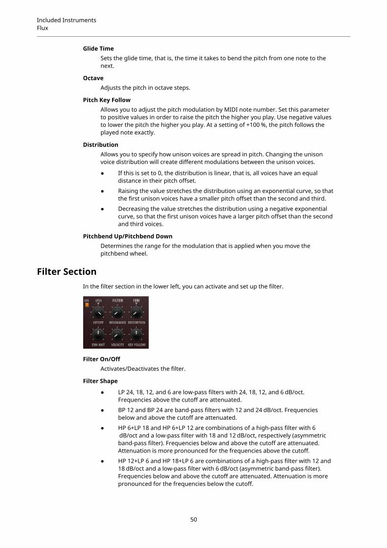
Included InstrumentsFlux
Glide TimeSets the glide time, that is, the time it takes to bend the pitch from one note to thenext.
OctaveAdjusts the pitch in octave steps.
Pitch Key FollowAllows you to adjust the pitch modulation by MIDI note number. Set this parameterto positive values in order to raise the pitch the higher you play. Use negative valuesto lower the pitch the higher you play. At a setting of +100 %, the pitch follows theplayed note exactly.
DistributionAllows you to specify how unison voices are spread in pitch. Changing the unisonvoice distribution will create different modulations between the unison voices.
● If this is set to 0, the distribution is linear, that is, all voices have an equaldistance in their pitch offset.
● Raising the value stretches the distribution using an exponential curve, so thatthe first unison voices have a smaller pitch offset than the second and third.
● Decreasing the value stretches the distribution using a negative exponentialcurve, so that the first unison voices have a larger pitch offset than the secondand third voices.
Pitchbend Up/Pitchbend DownDetermines the range for the modulation that is applied when you move thepitchbend wheel.
Filter SectionIn the filter section in the lower left, you can activate and set up the filter.
Filter On/OffActivates/Deactivates the filter.
Filter Shape
● LP 24, 18, 12, and 6 are low-pass filters with 24, 18, 12, and 6 dB/oct.Frequencies above the cutoff are attenuated.
● BP 12 and BP 24 are band-pass filters with 12 and 24 dB/oct. Frequenciesbelow and above the cutoff are attenuated.
● HP 6+LP 18 and HP 6+LP 12 are combinations of a high-pass filter with 6 dB/oct and a low-pass filter with 18 and 12 dB/oct, respectively (asymmetricband-pass filter). Frequencies below and above the cutoff are attenuated.Attenuation is more pronounced for the frequencies above the cutoff.
● HP 12+LP 6 and HP 18+LP 6 are combinations of a high-pass filter with 12 and18 dB/oct and a low-pass filter with 6 dB/oct (asymmetric band-pass filter).Frequencies below and above the cutoff are attenuated. Attenuation is morepronounced for the frequencies below the cutoff.
50

Included InstrumentsFlux
● HP 24, 18, 12, and 6 are high-pass filters with 24, 18, 12, and 6 dB/oct.Frequencies below the cutoff are attenuated.
● BR 12 and BR 24 are band-reject filters with 12 and 24 dB/oct. Frequenciesaround the cutoff are attenuated.
● BR 12+LP 6 and BR 12+LP 12 are combinations of a band-reject filter with 12 dB/oct and a low-pass filter with 6 and 12 dB/oct, respectively. Frequenciesaround and above the cutoff are attenuated.
● BP 12+BR 12 is a band-pass filter with 12 dB/oct plus a band-reject filter with12 dB/oct. Frequencies below, above, and around the cutoff are attenuated.
● HP 6+BR 12 and HP 12+BR 12 are combinations of a high-pass filter with 6and 12 dB/oct and a band-reject filter with 12 dB/oct. Frequencies below andaround the cutoff are attenuated.
● AP is an all-pass filter with 18 dB/oct. Frequencies around the cutoff areattenuated.
● AP+LP 6 is an all-pass filter with 18 dB/oct plus a low-pass filter with 6 dB/oct.Frequencies around and above the cutoff are attenuated.
● HP 6+AP is a high-pass filter with 6 dB/oct plus an all-pass filter with 18 dB/oct.Frequencies around and below the cutoff are attenuated.
CutoffControls the cutoff frequency of the filter.
ResonanceEmphasizes the frequencies around the cutoff. At higher settings, the filter self-oscillates, which results in a ringing tone.
DistortionAdds distortion to the signal. The following distortion types are available:
● Tube adds warm, tube-like distortion.
● Hard Clip adds bright, transistor-like distortion.
● Bit Reduction adds digital distortion by means of quantization noise.
● Rate Reduction adds digital distortion by means of aliasing.
● Rate Reduction Key Follow adds digital distortion by means of aliasing, butwith Key Follow. The rate reduction follows the keyboard, so the higher youplay, the higher the sample rate.
Envelope AmountControls the cutoff modulation from the filter envelope.
Cutoff VelocityControls the cutoff modulation from velocity.
Cutoff Key FollowAdjusts the cutoff modulation using the note number. Increase this parameterto raise the cutoff with higher notes. At 100 %, the cutoff follows the played pitchexactly.
51

Included InstrumentsFlux
Filter EnvelopeOn the left on the Env F/A tab, you can set up the filter envelope.
AttackControls the attack time of the filter envelope.
DecayControls the decay time of the filter envelope.
SustainControls the sustain level of the filter envelope.
ReleaseControls the release time of the filter envelope.
Amplifier and Amplifier EnvelopeOn the right of the Env F/A tab, you can make settings for the amplifier and the amplifierenvelope.
Amplifier Parameters
LevelControls the overall volume of the sound.
VelocityControls the level modulation from velocity. At 0, all notes are played with the samelevel.
Amplifier Envelope Parameters
AttackControls the attack time of the amplifier envelope.
DecayControls the decay time of the amplifier envelope.
SustainControls the sustain level of the amplifier envelope.
52
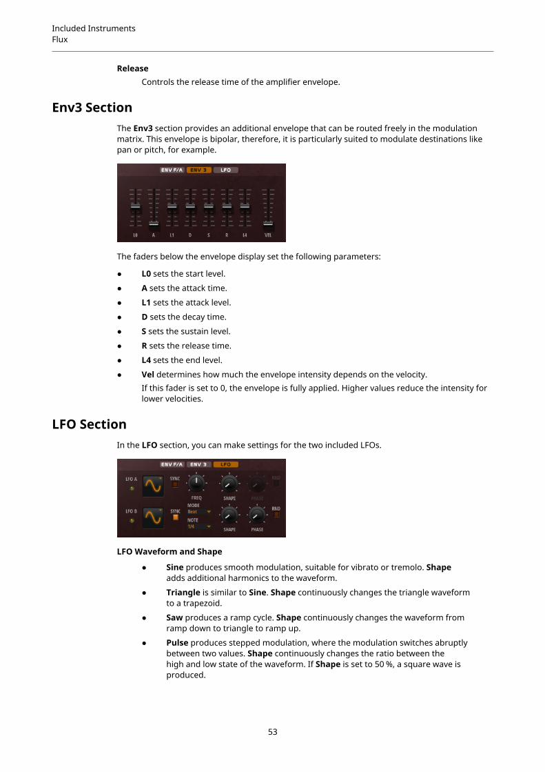
Included InstrumentsFlux
ReleaseControls the release time of the amplifier envelope.
Env3 SectionThe Env3 section provides an additional envelope that can be routed freely in the modulationmatrix. This envelope is bipolar, therefore, it is particularly suited to modulate destinations likepan or pitch, for example.
The faders below the envelope display set the following parameters:
● L0 sets the start level.
● A sets the attack time.
● L1 sets the attack level.
● D sets the decay time.
● S sets the sustain level.
● R sets the release time.
● L4 sets the end level.
● Vel determines how much the envelope intensity depends on the velocity.If this fader is set to 0, the envelope is fully applied. Higher values reduce the intensity forlower velocities.
LFO SectionIn the LFO section, you can make settings for the two included LFOs.
LFO Waveform and Shape
● Sine produces smooth modulation, suitable for vibrato or tremolo. Shapeadds additional harmonics to the waveform.
● Triangle is similar to Sine. Shape continuously changes the triangle waveformto a trapezoid.
● Saw produces a ramp cycle. Shape continuously changes the waveform fromramp down to triangle to ramp up.
● Pulse produces stepped modulation, where the modulation switches abruptlybetween two values. Shape continuously changes the ratio between thehigh and low state of the waveform. If Shape is set to 50 %, a square wave isproduced.
53
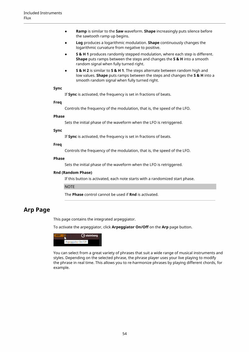
Included InstrumentsFlux
● Ramp is similar to the Saw waveform. Shape increasingly puts silence beforethe sawtooth ramp up begins.
● Log produces a logarithmic modulation. Shape continuously changes thelogarithmic curvature from negative to positive.
● S & H 1 produces randomly stepped modulation, where each step is different.Shape puts ramps between the steps and changes the S & H into a smoothrandom signal when fully turned right.
● S & H 2 is similar to S & H 1. The steps alternate between random high andlow values. Shape puts ramps between the steps and changes the S & H into asmooth random signal when fully turned right.
SyncIf Sync is activated, the frequency is set in fractions of beats.
FreqControls the frequency of the modulation, that is, the speed of the LFO.
PhaseSets the initial phase of the waveform when the LFO is retriggered.
SyncIf Sync is activated, the frequency is set in fractions of beats.
FreqControls the frequency of the modulation, that is, the speed of the LFO.
PhaseSets the initial phase of the waveform when the LFO is retriggered.
Rnd (Random Phase)If this button is activated, each note starts with a randomized start phase.
NOTE
The Phase control cannot be used if Rnd is activated.
Arp PageThis page contains the integrated arpeggiator.
To activate the arpeggiator, click Arpeggiator On/Off on the Arp page button.
You can select from a great variety of phrases that suit a wide range of musical instruments andstyles. Depending on the selected phrase, the phrase player uses your live playing to modifythe phrase in real time. This allows you to re-harmonize phrases by playing different chords, forexample.
54
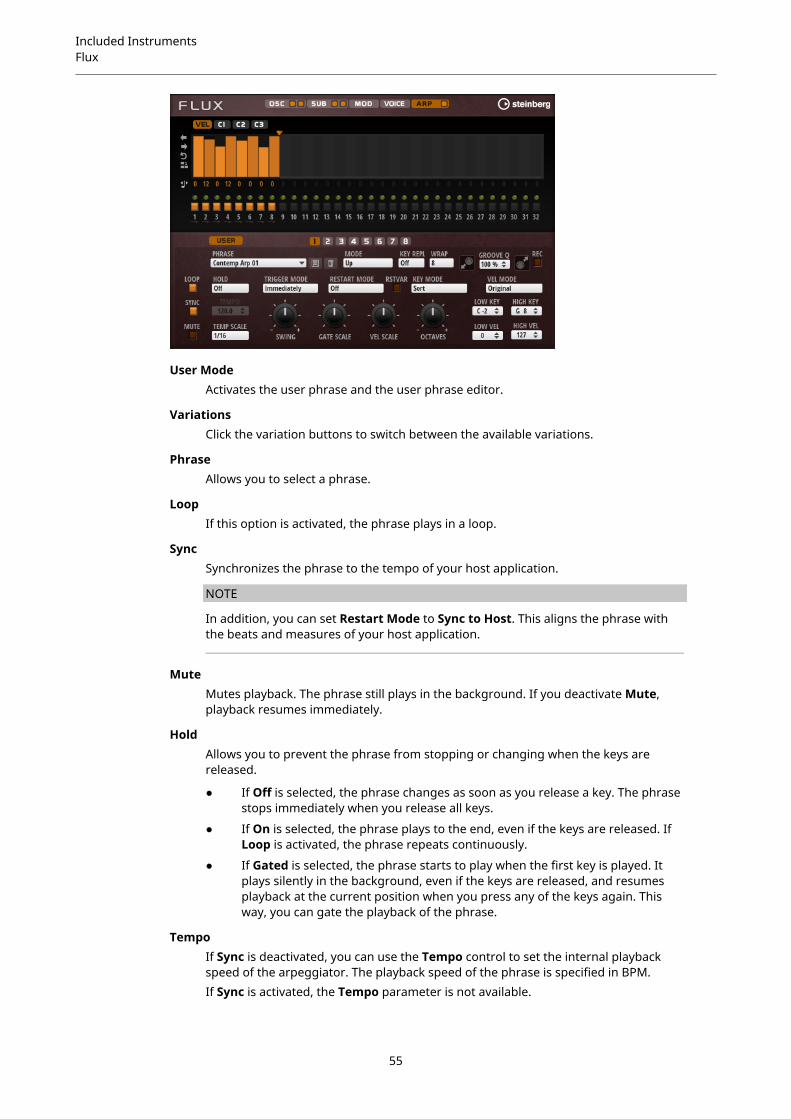
Included InstrumentsFlux
User ModeActivates the user phrase and the user phrase editor.
VariationsClick the variation buttons to switch between the available variations.
PhraseAllows you to select a phrase.
LoopIf this option is activated, the phrase plays in a loop.
SyncSynchronizes the phrase to the tempo of your host application.
NOTE
In addition, you can set Restart Mode to Sync to Host. This aligns the phrase withthe beats and measures of your host application.
MuteMutes playback. The phrase still plays in the background. If you deactivate Mute,playback resumes immediately.
HoldAllows you to prevent the phrase from stopping or changing when the keys arereleased.
● If Off is selected, the phrase changes as soon as you release a key. The phrasestops immediately when you release all keys.
● If On is selected, the phrase plays to the end, even if the keys are released. IfLoop is activated, the phrase repeats continuously.
● If Gated is selected, the phrase starts to play when the first key is played. Itplays silently in the background, even if the keys are released, and resumesplayback at the current position when you press any of the keys again. Thisway, you can gate the playback of the phrase.
TempoIf Sync is deactivated, you can use the Tempo control to set the internal playbackspeed of the arpeggiator. The playback speed of the phrase is specified in BPM.If Sync is activated, the Tempo parameter is not available.
55
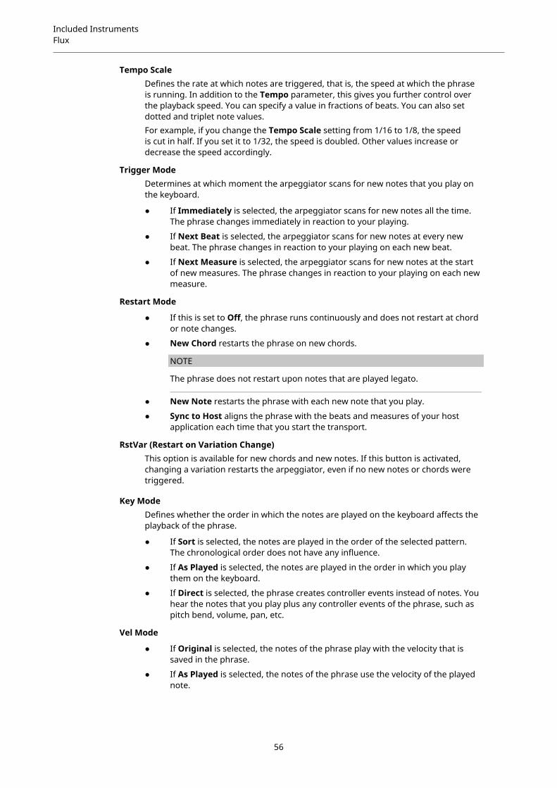
Included InstrumentsFlux
Tempo ScaleDefines the rate at which notes are triggered, that is, the speed at which the phraseis running. In addition to the Tempo parameter, this gives you further control overthe playback speed. You can specify a value in fractions of beats. You can also setdotted and triplet note values.For example, if you change the Tempo Scale setting from 1/16 to 1/8, the speedis cut in half. If you set it to 1/32, the speed is doubled. Other values increase ordecrease the speed accordingly.
Trigger ModeDetermines at which moment the arpeggiator scans for new notes that you play onthe keyboard.
● If Immediately is selected, the arpeggiator scans for new notes all the time.The phrase changes immediately in reaction to your playing.
● If Next Beat is selected, the arpeggiator scans for new notes at every newbeat. The phrase changes in reaction to your playing on each new beat.
● If Next Measure is selected, the arpeggiator scans for new notes at the startof new measures. The phrase changes in reaction to your playing on each newmeasure.
Restart Mode
● If this is set to Off, the phrase runs continuously and does not restart at chordor note changes.
● New Chord restarts the phrase on new chords.
NOTE
The phrase does not restart upon notes that are played legato.
● New Note restarts the phrase with each new note that you play.
● Sync to Host aligns the phrase with the beats and measures of your hostapplication each time that you start the transport.
RstVar (Restart on Variation Change)This option is available for new chords and new notes. If this button is activated,changing a variation restarts the arpeggiator, even if no new notes or chords weretriggered.
Key ModeDefines whether the order in which the notes are played on the keyboard affects theplayback of the phrase.
● If Sort is selected, the notes are played in the order of the selected pattern.The chronological order does not have any influence.
● If As Played is selected, the notes are played in the order in which you playthem on the keyboard.
● If Direct is selected, the phrase creates controller events instead of notes. Youhear the notes that you play plus any controller events of the phrase, such aspitch bend, volume, pan, etc.
Vel Mode
● If Original is selected, the notes of the phrase play with the velocity that issaved in the phrase.
● If As Played is selected, the notes of the phrase use the velocity of the playednote.
56

Included InstrumentsFlux
● If Original + As Played is selected, the phrase velocity is determined by thecombination of the velocity saved in the phrase and the velocity of the playednote.
SwingShifts the timing of notes on even-numbered beats. This way, the phrase gets aswing feeling. Negative values shift the timing backward and the notes are playedearlier. Positive values shift the timing forward and the notes are played later.
Gate ScaleAllows you to shorten or lengthen the notes of the phrase. At a value of 100 %, thenotes play with their original gate length.
Vel ScaleAllows you to raise or lower the note-on velocities of the phrase. At a value of 100 %,the notes are played with their original velocity.
OctavesExtends the phrase playback to include higher or lower octaves. Positive settingsextend the playback to higher and negative settings to lower octaves. For example, avalue of +1 first plays the phrase in the octave range that you originally played. Then,it repeats the phrase one octave higher.
User Mode Parameters
Save Phrase/Delete PhraseThe two buttons on the right of the phrase field allow you to save/delete yourphrases.
ModeDetermines how the notes are played back.
● If Step is selected, the last note that is received triggers a monophonicsequence.
● If Chord is selected, the notes are triggered as chords.
● If Up is selected, the notes are arpeggiated in ascending order.
● If Down is selected, the notes are arpeggiated in descending order.
● If Up/Down 1 is selected, the notes are arpeggiated first in ascending, then indescending order.
● If Up/Down 2 is selected, the notes are arpeggiated first in ascending, then indescending order. This mode depends on the set Key Mode.If Key Mode is set to Sort, the highest and the lowest note are repeated.If Key Mode is set to As Played, the first and the last note are repeated.
● If Down/Up 1 is selected, the notes are arpeggiated first in descending, thenin ascending order.
● If Down/Up 2 is selected, the notes are arpeggiated first in descending, thenin ascending order. This mode depends on the set Key Mode.If Key Mode is set to Sort, the highest and the lowest note are repeated.If Key Mode is set to As Played, the first and the last note are repeated.
● If Random is selected, the notes are arpeggiated in random order.
57

Included InstrumentsFlux
Key ReplaceWith this parameter, you can deactivate the Key Select function or specify howmissing keys are replaced.For example, if Key Select is set to 1 - 2 - 3 - 4 and you play a chord with 3 notes, key4 is considered missing.
● Off deactivates Key Replace and Key Select. The selected arpeggio plays backnormally.
● Arp replaces the missing keys with the note that the arpeggio would normallyplay.
● Rest does not replace any missing keys. The arpeggio plays a rest instead.
● 1st replaces the missing keys with the first note in the note buffer.
● Last replaces the missing keys with the last note in the note buffer.
● All replaces the missing keys with all notes in the note buffer. The notes areplayed as a chord.
WrapFor all modes except Step and Chord, you can use this parameter to restart thearpeggio after a specified number of steps.
NOTE
Deactivated steps are taken into account.
In Step and Chord mode, this parameter only affects the Octaves setting.If the Octaves parameter is active, the arpeggio traverses the octaves and restartsfrom the original octave after the specified number of steps.
Groove QuantizeTo adapt the timing of a pattern to an external MIDI file, you can drop this MIDI fileon the Groove Quantize drop field.The Groove Quantize Depth parameter to the right of the drop field determineshow accurately the pattern follows the timing of the MIDI file.
Drag Recorded MIDI to SequencerAllows you to drag the recorded MIDI phrase to your host sequencer.
Record OutputAllows you to record the MIDI output of the arpeggiator.
Recording the MIDI Output of the ArpeggiatorThe phrases that are played by the instrument depend on the played notes and can thereforenot be exported directly. However, it is possible to generate exportable phrases by recording theMIDI output of the arpeggiator.
PROCEDURE
1. Click Record MIDI Output.The arrow in the Drag MIDI field starts blinking to indicate record mode.
2. Play some notes.
3. When you are done, click Record MIDI Output again.Recording stops. In the Drag MIDI field, the arrow remains lit to indicate that a MIDIphrase can be exported.
58
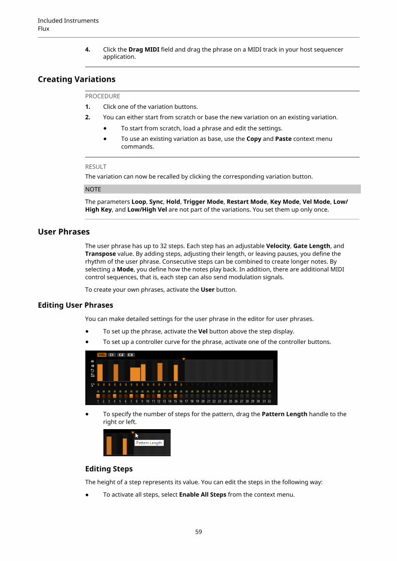
Included InstrumentsFlux
4. Click the Drag MIDI field and drag the phrase on a MIDI track in your host sequencerapplication.
Creating Variations
PROCEDURE
1. Click one of the variation buttons.
2. You can either start from scratch or base the new variation on an existing variation.
● To start from scratch, load a phrase and edit the settings.
● To use an existing variation as base, use the Copy and Paste context menucommands.
RESULTThe variation can now be recalled by clicking the corresponding variation button.
NOTE
The parameters Loop, Sync, Hold, Trigger Mode, Restart Mode, Key Mode, Vel Mode, Low/High Key, and Low/High Vel are not part of the variations. You set them up only once.
User PhrasesThe user phrase has up to 32 steps. Each step has an adjustable Velocity, Gate Length, andTranspose value. By adding steps, adjusting their length, or leaving pauses, you define therhythm of the user phrase. Consecutive steps can be combined to create longer notes. Byselecting a Mode, you define how the notes play back. In addition, there are additional MIDIcontrol sequences, that is, each step can also send modulation signals.
To create your own phrases, activate the User button.
Editing User Phrases
You can make detailed settings for the user phrase in the editor for user phrases.
● To set up the phrase, activate the Vel button above the step display.
● To set up a controller curve for the phrase, activate one of the controller buttons.
● To specify the number of steps for the pattern, drag the Pattern Length handle to theright or left.
Editing Steps
The height of a step represents its value. You can edit the steps in the following way:
● To activate all steps, select Enable All Steps from the context menu.
59

Included InstrumentsFlux
● To adjust a value, click a step and drag up or down.
● To adjust multiple steps, click and draw a curve.
● To adjust the velocity of all steps relatively, Shift-click and drag.
● To draw a ramp with steps, hold down Alt and draw a line.
● To draw symmetric ramps at the beginning and the end of the sequence, hold downShift-Alt and draw a line.
● To transpose a step, click in the field below it and enter the number of semitones for thetransposition.
NOTE
You can only transpose steps if Show Transpose Values is activated.
● To reset the velocity of a step to 127, Ctrl/Cmd-click the step.
● To reset the velocity of all steps to 127, hold Shift-Ctrl/Cmd and click a step.
● To introduce a legato between 2 steps, click the number below the first of these steps, sothat a small arrow is shown.If Legato is activated, the Gate Scale parameter is not taken into account.
For velocity steps, the width of a step represents its gate length.
● To adjust the gate length of a step, drag its right border.
● To adjust the gate length of all steps, hold down Shift and drag the right border of a step.You can only adjust the length this way until a step reaches the next step. If you increasethe gate length of a step so that it overlaps the following step, this following step isdeactivated.
● To reset the length of a step to 1, Ctrl/Cmd-click its highlighted right border.
● To reset the length of all steps, hold down Shift-Ctrl/Cmd and click on a highlighted rightborder.
● To fill the gaps between consecutive steps, select Fill Gap or Fill All Gaps from the contextmenu.
Each MIDI controller lane can send a MIDI controller.
Adjusting the Phrase
● To shift the rhythm of the phrase, click Shift Phrase Right or Shift Phrase Left .If you shift the rhythm of the phrase to the left, the first step is moved to the end. If youshift the phrase to the right, the last step is moved to the beginning.
● To reverse the phrase, click Reverse Phrase .
● To duplicate short phrases, click Duplicate Phrase .
NOTE
The maximum number of steps is 32. Therefore, phrases that contain more than 16 stepscannot be duplicated entirely.
60
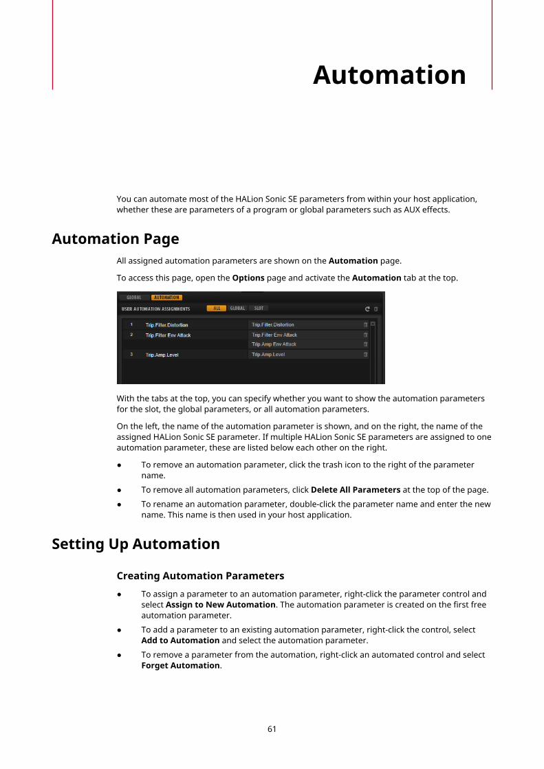
Automation
You can automate most of the HALion Sonic SE parameters from within your host application,whether these are parameters of a program or global parameters such as AUX effects.
Automation PageAll assigned automation parameters are shown on the Automation page.
To access this page, open the Options page and activate the Automation tab at the top.
With the tabs at the top, you can specify whether you want to show the automation parametersfor the slot, the global parameters, or all automation parameters.
On the left, the name of the automation parameter is shown, and on the right, the name of theassigned HALion Sonic SE parameter. If multiple HALion Sonic SE parameters are assigned to oneautomation parameter, these are listed below each other on the right.
● To remove an automation parameter, click the trash icon to the right of the parametername.
● To remove all automation parameters, click Delete All Parameters at the top of the page.
● To rename an automation parameter, double-click the parameter name and enter the newname. This name is then used in your host application.
Setting Up Automation
Creating Automation Parameters
● To assign a parameter to an automation parameter, right-click the parameter control andselect Assign to New Automation. The automation parameter is created on the first freeautomation parameter.
● To add a parameter to an existing automation parameter, right-click the control, selectAdd to Automation and select the automation parameter.
● To remove a parameter from the automation, right-click an automated control and selectForget Automation.
61

AutomationSetting Up Automation
● To assign a parameter to an automation parameter automatically while working in yourhost application, activate Automation Read/Write, start playback, and use the controls onthe HALion Sonic SE interface.
62

MIDI Editing and Controllers
MIDI PageThe MIDI page gives you access to the MIDI slot parameters of HALion Sonic SE.
Parameters
ChannelThe slot receives MIDI signals on the MIDI port and channel that are specified here.You can set multiple slots to the same MIDI channel and trigger them simultaneouslywith the same note events.
PolyphonySpecifies how many notes can be played at the same time.
NOTE
Programs can contain various layers, therefore, the resulting number of voices canbe much higher than the value that is specified here.
TransposeAllows you to shift the incoming MIDI notes by ±64 semitones before they are sent tothe loaded program.
Key Range (Low Key, High Key)Allows you to limit the key range for a slot.
63

MIDI Editing and ControllersMIDI Controllers
Velocity Range (Low Vel, High Vel)Allows you to limit the velocity range for a slot.
Controller FilterAllows you to filter out the most commonly used MIDI controllers.
Editing the Key RangeEach slot can be limited to a specific key range.
To show the key range, activate the Key button above the range controls.
You can set the key range in the following ways:
● Set the range with the Low Key and High Key value fields or by dragging the ends of thekeyboard range control.
● To move the key range, click in the middle of the range control and drag.
● To set the range via MIDI input, double-click in a value field and play the note.
Editing the Velocity RangeEach slot can be limited to a specific velocity range.
To show the velocity range, activate the Vel button above the range controls.
● Set the velocity range with the Low Vel and High Vel value fields or by dragging the endsof the velocity range control.To move the velocity range, click in the middle of the range control and drag.
MIDI ControllersYou can assign the parameters volume, pan, mute, solo, send FX 1–4, and the quick controlsof each slot to a MIDI controller. In addition to the slot parameters, you can also assign theparameters of the AUX FX and most of the edit parameters.
By default, volume, pan, send FX 1–4, and the program quick controls are already assigned. Youcan customize this factory MIDI controller mapping by assigning your own MIDI controllers. Thisway, you can adapt the mapping to your MIDI keyboard or controller.
To provide more control, you can set the minimum and maximum range for each assignmentseparately.
Assigning MIDI ControllersTo assign a MIDI controller to a parameter, proceed as follows:
PROCEDURE
1. Right-click the control that you want to control remotely and select Learn CC.
2. On your MIDI keyboard or controller, use the potentiometer, fader, or button.The next time you right-click the control, the menu shows the assigned MIDI controller.
NOTE
You can assign the same MIDI controller several times to different parameters. However,you cannot assign different MIDI controllers to the same parameter.
64
MIDI Editing and ControllersMIDI Controllers
Unassigning MIDI Controllers
PROCEDURE
● To remove a MIDI controller assignment, right-click the control and select Forget CC.
Restoring the Factory MIDI Controller AssignmentTo restore the factory MIDI controller assignments, open the Options page and click Reset toFactory in the MIDI Controller section.
Setting the Parameter RangeYou can set the minimum and maximum values for the parameter for each assignmentseparately. This gives you more control over the parameter, for example, when you areperforming live on stage.
PROCEDURE
1. Set the parameter to the minimum value.
2. Right-click the control and select Set Minimum from the context menu.
3. Set the parameter to the maximum value.
4. Right-click the control and select Set Maximum.
MIDI Controllers and AUX FXYou can assign the parameters of the AUX FX to MIDI controllers.
Unlike the slots, the AUX FX do not have a MIDI port and channel of their own. Instead, theylisten to any incoming MIDI controller message, regardless of the MIDI channel. Therefore, if youassign a parameter to a MIDI controller, you should use a controller number that is not alreadyin use by any of the assignments that you made for the slots.
NOTE
If you unload or replace the effect, the MIDI controller assignment of this effect is lost.
Saving a MIDI Controller Mapping as DefaultAfter customizing the factory MIDI controller assignments, you can save them as default.
PROCEDURE
● Open the Options Editor and, in the MIDI Controller section, click Save as Default.
RESULTNow, each time that you load a new instance of the plug-in, your customized MIDI controllermapping is available as default.
NOTE
● Saving the controller mapping as default does not include the MIDI controller assignmentsof the AUX FX.
● The MIDI controller mapping is saved with each project. This way, you can transfer yoursettings to other systems. The project also includes the MIDI controller assignments of theAUX FX.
65

MIDI Editing and ControllersMIDI Controllers
Automation and Factory MIDI Controller AssignmentSeveral parameters on the plug-in interface are available for automation from your host softwareand can be assigned to an external MIDI controller.
The table shows the controller numbers and names of the default factory MIDI controllerassignment. The assigned MIDI controller numbers are the same for all slots. However, the MIDIcontrollers listen only to the MIDI channels of the corresponding slot.
Parameter Controller Number Name
Volume #7 Volume
Pan #10 Pan
Send FX 1 #91 Effect 1 Depth
Send FX 2 #92 Effect 2 Depth
Send FX 3 #93 Effect 3 Depth
Send FX 4 #94 Effect 4 Depth
Program QC 1 #74 Brightness
Program QC 2 #71 Harmonic Content
Program QC 3 #73 Attack Time
Program QC 4 #72 Release Time
Program QC 5 #75 Sound Controller #6
Program QC 6 #76 Sound Controller #7
Program QC 7 #77 Sound Controller #8
Program QC 8 #78 Sound Controller #9
NOTE
● Send FX 1-4 are only available if the corresponding AUX send effects are loaded.
● You can remotely control any other parameter by assigning the parameter first to a quickcontrol and then to a MIDI controller.
● You can use MIDI controllers inside the modulation matrix of a synth or sample layer tocontrol the cutoff, for example.
66
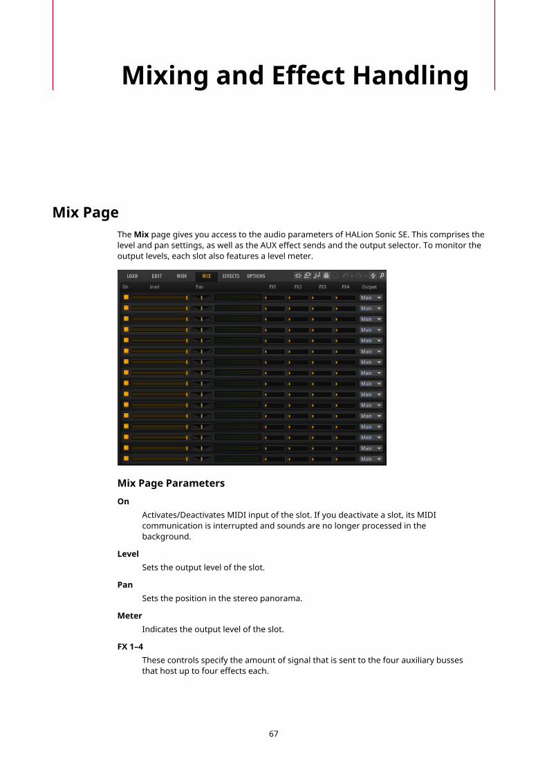
Mixing and Effect Handling
Mix PageThe Mix page gives you access to the audio parameters of HALion Sonic SE. This comprises thelevel and pan settings, as well as the AUX effect sends and the output selector. To monitor theoutput levels, each slot also features a level meter.
Mix Page Parameters
OnActivates/Deactivates MIDI input of the slot. If you deactivate a slot, its MIDIcommunication is interrupted and sounds are no longer processed in thebackground.
LevelSets the output level of the slot.
PanSets the position in the stereo panorama.
MeterIndicates the output level of the slot.
FX 1–4These controls specify the amount of signal that is sent to the four auxiliary bussesthat host up to four effects each.
67
Mixing and Effect HandlingEffect Handling
OutputSpecifies to which of the 16 plug-in outputs the slot is routed.
Effect HandlingThe busses can be routed to the main plug-in output or to one of the individual outputs.
The Effects page also provides access to the main output bus which also features four inserts.These can be used to add a global EQ or compressor to the signal chain, for example.
Default Effect Settings
Each effect comes with factory default settings. However, you can save your own default settingsfor each effect as a preset.
● Set up the effect.
● Click the Save Preset button in the title bar of the effect section and save the preset underthe name “--Default--”.
The preset is saved in the presets folder of the effect and is loaded each time you load the effect.
● To return to the factory default settings, delete your default preset.
Using the Insert Effect SlotsOn the Effects page, you can set up insert effects for AUX busses.
Each bus provides four slots for insert effects.
● To assign an insert effect, click the effect slot and select the effect from the menu.
● To remove an insert effect including its current settings, click the effect slot and selectNone from the menu.
● To deactivate an effect without removing it, click its On/Off button above the slot. Thisway, you can switch off the effect without losing its settings.
● To bypass an effect, activate the Bypass button of the slot. Bypass is active when thebutton lights up.
● To edit an insert effect, click the e button of the corresponding slot. You can edit only oneeffect at a time. The parameters of the insert effect are displayed in the bottom section.
● To move an effect to another slot, click its drag icon and drag it to another slot. Thisreplaces any effect loaded in this slot.
● To change the order of the effects, drag them by their drag icon to a new position betweentwo slots.
● To copy an effect into another slot, Alt-click the drag icon and drag it onto the new slot.This replaces any effect loaded in this slot.
NOTE
You can also copy effects between the different mixers. First drag an effect to thecorresponding mixer tab. Then drag it to the position where you want to insert it.
● To copy an effect and insert it between two effect slots, Alt-click its drag icon and drag itbetween two slots.
NOTE
You can also copy effects between the different mixers. First drag an effect to thecorresponding mixer tab. Then drag it to the position where you want to insert it.
68

Library Manager
HALion Sonic SE’s Library Manager allows you to register and manage VST Sound libraries.Libraries created with HALion 6 and newer are handled differently and allow for more actionsthan libraries that were installed with a classic installer.
The Library Manager is installed on your computer as a standalone application and can be runindependently from other Steinberg products.
For actions such as registering, moving, or deleting libraries, the Library Manager requires fullaccess to all VST Sound libraries. Therefore, you must close your Steinberg plug-ins and DAWfirst, so that they release these files.
Library Manager EditorAll HALion-family libraries available on your system are displayed in the Library Manager.
The libraries on the Managed tab were created with HALion 6 or newer. They can be removedfrom your system or moved to another location using the Library Manager functions.
The libraries on the Installed tab were installed with an installation program, for example withSteinberg’s Cubase. These libraries cannot be moved or deleted using the Library Manager. Forthis, you must use the Uninstall function of the original installation program or the operatingsystem.
69
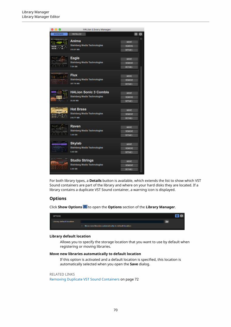
Library ManagerLibrary Manager Editor
For both library types, a Details button is available, which extends the list to show which VSTSound containers are part of the library and where on your hard disks they are located. If alibrary contains a duplicate VST Sound container, a warning icon is displayed.
Options
Click Show Options to open the Options section of the Library Manager.
Library default locationAllows you to specify the storage location that you want to use by default whenregistering or moving libraries.
Move new libraries automatically to default locationIf this option is activated and a default location is specified, this location isautomatically selected when you open the Save dialog.
RELATED LINKSRemoving Duplicate VST Sound Containers on page 72
70
Library ManagerLibrary Manager Editor
Installing VST Sound LibrariesTo install a new library, you must register the corresponding VST Sound container files.
PROCEDURE
1. Navigate to the folder where the new VST Sound container files are located and double-click one of them.
2. If a default location is specified in the Options section of the Library Manager, thislocation is automatically entered in the dialog. If no default location is set, you mustspecify the location manually.To keep your system clean and uncluttered, you might want to create a dedicated folderfor all your libraries and then create subfolders for each new library. You can also createmultiple library folders on different hard disks.
3. Click OK.
RESULTThe libraries in the selected folder are registered to the MediaBay of HALion, HALion Sonic, andHALion Sonic SE, as well as your Steinberg DAW, and can be used the next time that you openHALion Sonic SE.
RELATED LINKSLibrary Manager Editor on page 69
Moving LibrariesYou can move the file location of a library, for example, to a faster SSD hard disk or because youhave accidentally registered it from the wrong folder and you do not want it to remain in thislocation.
PROCEDURE
1. Navigate to the library in the list and click Move.
2. In the dialog, navigate to the new location and click OK.
Removing LibrariesYou can remove a library if you do not want to use its contents any longer.
PROCEDURE
● Navigate to the library in the list and click its Remove button.
NOTE
● Libraries can have dependencies to other libraries, for example, if a preset libraryis based on samples that were delivered exclusively with another library. If you tryto delete this second library, the Library Manager will warn you that this library isrequired by another library.
71

Library ManagerLibrary Manager Editor
Removing Duplicate VST Sound ContainersIf duplicate VST Sound containers are found on your system, a warning icon lights up on theLibrary Manager toolbar.
● To remove the duplicate or duplicates, click the warning icon and select RemoveDuplicates.This removes the container with the older internal version number. If both files areidentical, the container that is located in the default library location is kept.
72

Effects Reference
Reverb Effects
REVerenceREVerence is a convolution tool that allows you to apply room characteristics (reverb) to theaudio.
By recording an impulse in a room, you capture the characteristics of this room. Convolutionsuperimposes these characteristics to the sound. The result is a very natural sounding reverb.Included with this effect is a collection of high-quality reverb impulse responses.
Impulse ResponseAllows you to select an impulse response. This determines the basic sound characterof the reverb.
ReverseReverses the impulse response.
PredelayDetermines the amount of time between the dry signal and the onset of the reverb.With higher predelay values, you can simulate larger rooms.
TimeControls the reverb time. At a setting of 100 %, the impulse response is applied withits original length.
SizeScales the size of the simulated room. At a setting of 100 %, the impulse response isapplied as recorded in the original room.
LevelAdjusts the level of the impulse response.
EqualizerActivates the built-in three-band equalizer.
73

Effects ReferenceReverb Effects
ER/Tail SplitSets the split point between the early reflections and the reverb tail.
ER/Tail MixSets the balance between the early reflections and the reverb tail. At a setting of50 % the early reflections and the tail have the same volume level. Settings below50 % raise the early reflections and lower the tail, as a result the sound source movestowards the front of the room. Settings above 50 % raise the tail and lower the earlyreflections, as a result the sound source moves towards the back of the room.
ReverbThis effect produces a high-quality algorithmic reverb with early reflections and reverb tail.
The early reflections are responsible for the spatial impression in the first milliseconds ofthe reverb. For emulating different rooms, you can choose between different early reflectionpatterns and adjust their size. The reverb tail, or late reverberation, offers parameters forcontrolling the room size and the reverb time. You can adjust the reverb time individually in threefrequency bands.
PredelayDetermines how much time passes before the reverb is applied. This allows you tosimulate larger rooms by increasing the time it takes for the first reflections to reachthe listener.
Early ReflectionsHere, you select an early reflections pattern. The early reflections pattern containsthe most important delays that deliver the key information for the spatial impressionof the room.
Show Early Reflections Page/Show Chorusing PageWith these two buttons below the Early Reflections pop-up menu, you can choosewhether to display the early reflections settings or the chorusing settings in thelower left part of the effect panel.
ER/TailSets the level balance between the early reflections and the reverb tail. At a setting of50 %, early reflections and tail have the same volume. Settings below 50 % raise theearly reflections and lower the tail, as a result the sound source moves towards thefront of the room. Settings above 50 % raise the tail and lower the early reflections,as a result the sound source moves toward the back of the room.
DelayDelays the onset of the reverb tail.
Room SizeControls the dimensions of the simulated room. At a setting of 100 %, the dimensionscorrespond to a cathedral or a large concert hall. At a setting of 50 %, the dimensionscorrespond to a medium-sized room or studio. Settings below 50 % simulate thedimensions of small rooms or a booth.
74
Effects ReferenceReverb Effects
Main TimeControls the overall reverb time of the tail. The higher this value, the longer thereverb tail will decay. At a setting of 100 %, the reverb time is infinitely long. TheMain Time parameter also represents the mid band of the reverb tail.
High TimeControls the reverb time for the high frequencies of the reverb tail. With positivevalues, the decay time of the high frequencies is longer. With negative values, it isshorter. Frequencies are affected depending on the High Freq parameter.
Low TimeControls the reverb time for the low frequencies of the reverb tail. With positivevalues, low frequencies decay longer and vice versa. Frequencies will be affecteddepending on the Low Freq parameter.
High FreqSets the cross-over frequency between the mid and the high band of the reverb tail.You can offset the reverb time for frequencies above this value from the main reverbtime with the High Time parameter.
Low FreqSets the cross-over frequency between the low and the mid band of the reverb tail.The reverb time for frequencies below this value can be offset from the main reverbtime with the Low Time parameter.
SizeAdjusts the length of the early reflections pattern. At a setting of 100 %, the patternis applied with its original length and the room sounds the most natural. At settingsbelow 100 %, the early reflections pattern is compressed and the room is perceivedsmaller.
ER Low CutAttenuates the low frequencies of the early reflections. The higher this value, thefewer low frequencies are present in the early reflections.
ER High CutAttenuates the high frequencies of the early reflections. The lower this value, thefewer high frequencies the early reflections will have.
ShapeControls the attack of the reverb tail. At a setting of 0 %, the attack is moreimmediate, which is a good setting for drums. The higher this value, the lessimmediate the attack.
DensityAdjusts the echo density of the reverb tail. At a setting of 100 %, single reflectionsfrom walls cannot be heard. The lower this value, the more single reflections can beheard.
Tail High CutAttenuates the high frequencies of the reverb tail. The lower this value, the fewerhigh frequencies the reverb tail will have.
WidthAdjusts the output of the reverb signal between mono and stereo. At a setting of 0 %,the output of the reverb is mono, at 100 % it is stereo.
MixSets the ratio between the dry and the wet signal.
75

Effects ReferenceDelay Effects
Chorusing
Chorusing allows you to enrich the reverb tail through subtle pitch modulations. To access thechorusing parameters, click the Show Chorusing Page button.
Chorusing On/OffActivates/Deactivates the chorusing effect.
Chorusing RateSpecifies the frequency of the pitch modulation.
Chorusing DepthSets the intensity of the pitch modulation.
Delay Effects
Multi DelayThis effect produces delays, with adjustable time, feedback, and filters.
Mode
● Stereo has two independent delay lines, one for the left and one for the rightaudio channel, each with a feedback path of its own.
● Cross has two delay lines with cross feedback, where the delay of the leftchannel is fed back into the delay of the right channel, and vice versa.
● Ping-Pong mixes the left and right input channels and sends the mixed signalto hard-panned left and right delays. This way, the echoes bounce like a ping-pong ball between left and right in the stereo panorama.
TimeSets the overall time for the left and right delay. Use the Delay L/R parameter toshorten the time for the left or right delay.
SyncActivate Sync to synchronize the delay time to the host tempo. If Sync is activated,the time is set as a note value.
NOTE
The maximum delay time is 5000 ms. If the note length exceeds this value, it isautomatically shortened.
Delay L/ROffsets the time of the left or right delay from the overall delay time. At a factor of 1,the right or left delay time has the same length as the overall delay time. At a factorof 0.5, the time is half as long as the overall delay time.
● To offset the left delay time, turn the control to the left.
76
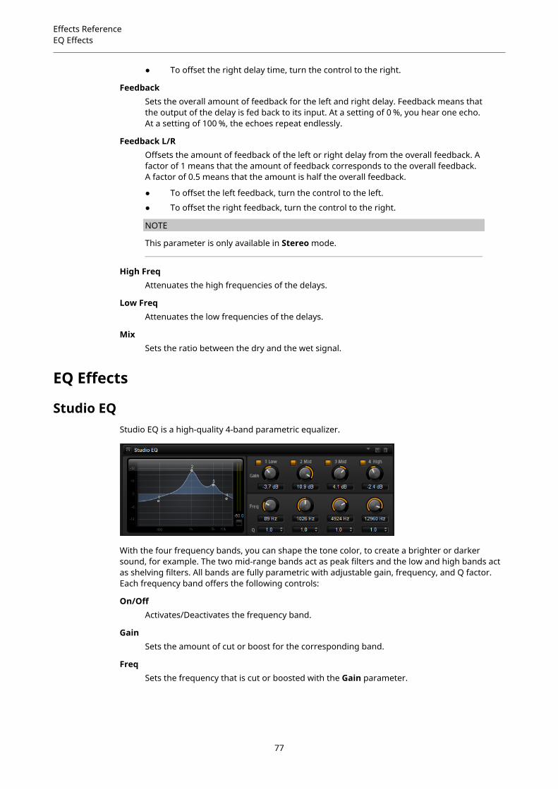
Effects ReferenceEQ Effects
● To offset the right delay time, turn the control to the right.
FeedbackSets the overall amount of feedback for the left and right delay. Feedback means thatthe output of the delay is fed back to its input. At a setting of 0 %, you hear one echo.At a setting of 100 %, the echoes repeat endlessly.
Feedback L/ROffsets the amount of feedback of the left or right delay from the overall feedback. Afactor of 1 means that the amount of feedback corresponds to the overall feedback.A factor of 0.5 means that the amount is half the overall feedback.
● To offset the left feedback, turn the control to the left.
● To offset the right feedback, turn the control to the right.
NOTE
This parameter is only available in Stereo mode.
High FreqAttenuates the high frequencies of the delays.
Low FreqAttenuates the low frequencies of the delays.
MixSets the ratio between the dry and the wet signal.
EQ Effects
Studio EQStudio EQ is a high-quality 4-band parametric equalizer.
With the four frequency bands, you can shape the tone color, to create a brighter or darkersound, for example. The two mid-range bands act as peak filters and the low and high bands actas shelving filters. All bands are fully parametric with adjustable gain, frequency, and Q factor.Each frequency band offers the following controls:
On/OffActivates/Deactivates the frequency band.
GainSets the amount of cut or boost for the corresponding band.
FreqSets the frequency that is cut or boosted with the Gain parameter.
77

Effects ReferenceEQ Effects
Q (Quality)Adjusts the bandwidth of the mid-range peak filters from wide to narrow. Byincreasing the Q value on the low and high shelving filters, you can add a dip to theirshape.
Graphic EQGraphic EQ is an equalizer with ten frequency bands that can be cut or boosted by up to 12 dB. Inaddition, you can specify the overall range and output of the equalizer.
OutputControls the overall output level of the equalizer.
ModeAllows you to add color or character to the equalized output. The following optionsare available:
● True Response mode uses serial filters with accurate frequency response.
● Classic mode uses parallel filters where the resonance depends on theamount of gain.
● Constant Q mode uses parallel filters where the resonance is raised whenboosting the gain.
RangeAdjusts the maximum cut or boost for all frequency bands together.
InvertActivate this to invert the EQ curve.
FlattenResets all frequency bands to 0 dB.
DJ-EQThis plug-in is an easy-to-use 3-band parametric equalizer that resembles the EQs found ontypical DJ mixers. This plug-in is designed for quick sound fixes.
Low Freq/Mid Freq/High FreqSet the amount of boost or attenuation for the low, mid, and high bands.
78

Effects ReferenceFilter Effects
You can also click and drag in the display to change these values.
Low Cut/Mid Cut/ High CutCut the low, mid, and high bands.
Reset Output Peak LevelResets the peak level that is displayed in the output meter.
Filter Effects
Auto FilterAuto Filter provides two morphable filter shapes with distortion.
The morphing between the two shapes, as well as the cutoff, can be controlled with a manualpedal control, an LFO, or an envelope shaper.
Filter Parameters
Filter Shape
● LP 24, 18, 12, and 6 are low-pass filters with 24, 18, 12, and 6 dB/oct.Frequencies above the cutoff are attenuated.
● BP 12 and BP 24 are band-pass filters with 12 and 24 dB/oct. Frequenciesbelow and above the cutoff are attenuated.
● HP 6+LP 18 and HP 6+LP 12 are combinations of a high-pass filter with 6 dB/oct and a low-pass filter with 18 and 12 dB/oct, respectively (asymmetricband-pass filter). Frequencies below and above the cutoff are attenuated.Attenuation is more pronounced for the frequencies above the cutoff.
● HP 12+LP 6 and HP 18+LP 6 are combinations of a high-pass filter with 12 and18 dB/oct and a low-pass filter with 6 dB/oct (asymmetric band-pass filter).Frequencies below and above the cutoff are attenuated. Attenuation is morepronounced for the frequencies below the cutoff.
● HP 24, 18, 12, and 6 are high-pass filters with 24, 18, 12, and 6 dB/oct.Frequencies below the cutoff are attenuated.
● BR 12 and BR 24 are band-reject filters with 12 and 24 dB/oct. Frequenciesaround the cutoff are attenuated.
● BR 12+LP 6 and BR 12+LP 12 are combinations of a band-reject filter with 12 dB/oct and a low-pass filter with 6 and 12 dB/oct, respectively. Frequenciesaround and above the cutoff are attenuated.
● BP 12+BR 12 is a band-pass filter with 12 dB/oct plus a band-reject filter with12 dB/oct. Frequencies below, above, and around the cutoff are attenuated.
● HP 6+BR 12 and HP 12+BR 12 are combinations of a high-pass filter with 6and 12 dB/oct and a band-reject filter with 12 dB/oct. Frequencies below andaround the cutoff are attenuated.
79

Effects ReferenceFilter Effects
● AP is an all-pass filter with 18 dB/oct. Frequencies around the cutoff areattenuated.
● AP+LP 6 is an all-pass filter with 18 dB/oct plus a low-pass filter with 6 dB/oct.Frequencies around and above the cutoff are attenuated.
● HP 6+AP is a high-pass filter with 6 dB/oct plus an all-pass filter with 18 dB/oct.Frequencies around and below the cutoff are attenuated.
InputAdjusts the gain before the filter and distortion. This parameter only affects the wetsignal.
CutoffSpecifies the cutoff frequency of the filter.
ResonanceEmphasizes the frequencies around the cutoff. At higher resonance settings, thefilter self-oscillates, which results in a ringing tone.
Distortion TypeThe following options are available:
● When this parameter is set to Off, the filter offers no distortion.
● Tube Drive offers a lot of character by adding warm, tube-like distortion.
● Hard Clip adds bright, transistor-like distortion.
● Bit Red adds digital distortion by means of quantization noise.
● Rate Red adds digital distortion by means of aliasing.
DistortionAdds distortion to the signal. The effect depends on the selected distortion type. Athigher settings, it creates a very intense distortion effect.
NOTE
This parameter is not available if Distortion Type is set to Off.
OutputAdjusts the gain after the filter and distortion. This parameter only affects the wetsignal.
MixSets the ratio between the dry and the wet signal.
LFO Section
LFO Waveform and ShapeWaveform selects the basic type of waveform. Shape changes the characteristic ofthe waveform.
● Sine produces smooth modulation. Shape adds additional harmonics to thewaveform.
● Triangle is similar in character to Sine. The waveform periodically ramps upand down. Shape continuously changes the triangle waveform to a trapezoid.
80
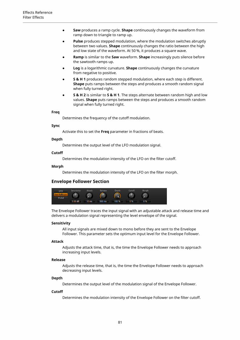
Effects ReferenceFilter Effects
● Saw produces a ramp cycle. Shape continuously changes the waveform fromramp down to triangle to ramp up.
● Pulse produces stepped modulation, where the modulation switches abruptlybetween two values. Shape continuously changes the ratio between the highand low state of the waveform. At 50 %, it produces a square wave.
● Ramp is similar to the Saw waveform. Shape increasingly puts silence beforethe sawtooth ramps up.
● Log is a logarithmic curvature. Shape continuously changes the curvaturefrom negative to positive.
● S & H 1 produces random stepped modulation, where each step is different.Shape puts ramps between the steps and produces a smooth random signalwhen fully turned right.
● S & H 2 is similar to S & H 1. The steps alternate between random high and lowvalues. Shape puts ramps between the steps and produces a smooth randomsignal when fully turned right.
FreqDetermines the frequency of the cutoff modulation.
SyncActivate this to set the Freq parameter in fractions of beats.
DepthDetermines the output level of the LFO modulation signal.
CutoffDetermines the modulation intensity of the LFO on the filter cutoff.
MorphDetermines the modulation intensity of the LFO on the filter morph.
Envelope Follower Section
The Envelope Follower traces the input signal with an adjustable attack and release time anddelivers a modulation signal representing the level envelope of the signal.
SensitivityAll input signals are mixed down to mono before they are sent to the EnvelopeFollower. This parameter sets the optimum input level for the Envelope Follower.
AttackAdjusts the attack time, that is, the time the Envelope Follower needs to approachincreasing input levels.
ReleaseAdjusts the release time, that is, the time the Envelope Follower needs to approachdecreasing input levels.
DepthDetermines the output level of the modulation signal of the Envelope Follower.
CutoffDetermines the modulation intensity of the Envelope Follower on the filter cutoff.
81

Effects ReferenceFilter Effects
MorphDetermines the modulation intensity of the Envelope Follower on the filter morph.
Pedal Section
PedalSets the position of the pedal.
DepthDetermines the output level of the pedal modulation signal.
CutoffDetermines the modulation intensity of the pedal on the filter cutoff.
MorphDetermines the modulation intensity of the pedal on the filter morph.
Morph FilterMorph Filter allows you to mix low-pass and high-pass filter effects, allowing for creativemorphings between two filters. You can specify the filter shapes independently for filter shape Aand B.
Filter Shape BHere, you can choose between several high-pass and band-rejection filter shapes.
Filter Shape AHere, you can select a low-pass or a band-pass filter shape.
MorphAllows you to mix the output between the two selected filters.
CutoffAdjusts the cutoff frequency of the filters.
NOTE
You can also set the Cutoff and Morph parameters simultaneously by clicking in thedisplay and dragging.
ResonanceEmphasizes the frequencies around the cutoff frequency. For an electronic sound,increase the resonance. At higher resonance settings, the filter self-oscillates, whichresults in a ringing tone.
82

Effects ReferenceFilter Effects
ResonatorThe sound of the human voice or of acoustic instruments can be characterized by their distinctiveformant regions, that is, by resonances in the frequency spectrum that are typical for a particularsound.
For example, the vowel “ah” (as in father) sung by a male singer has three characteristicformants: F1 = 570 Hz, F2 = 840 Hz, and F3 = 2410 Hz. The Resonator effect allows you to inducesuch formant regions to a sound by using three filters that are connected in parallel. You canspecify the positions and levels of the formant regions by adjusting the Cutoff, Resonance, andGain parameters of the filters.
The Resonator effect comes with 14 predefined filter shapes that determine the basic soundcharacter. In addition, three LFOs can be used to modulate each filter separately, which allowsfor adding extra motion to the sound.
Resonator ShapeDefines the basic sound character of the effect. Each shape is a unique combinationof different filter types for the low, mid, and high frequency bands.
Option Filter Low/Mid/High
Low-Pass 1 LP6/LP6/LP6
Low-Pass 2 LP12/LP12/LP12
Band-Pass 1 BP12/(-1)BP12/BP12*
Band-Pass 2 BP12/BP12/BP12
High-Pass 1 HP6/HP6/HP6
High-Pass 2 HP12/HP12/HP12
Peak 1 LP6/(-1)BP12/HP6*
Peak 2 LP6/BP12/HP6
Bat 1 HP12/BP12/LP12
Bat 2 HP6/BP12/LP6
Wings 1 LP6/BR12/HP6
Wings 2 HP12/BR12/LP12
Wings 3 LP6/(-1)BR12/HP6*
Wings 4 HP12/(-1)BR12/LP12*
*(-1) means that the phase is inverted
MixSets the ratio between the dry and the wet signal.
Cutoff SpreadSpreads the cutoff frequencies between the channels of the effect.For example, if the effect is used in stereo, positive Cutoff Spread values shift thecutoff down on the left channel and up on the right channel.
83
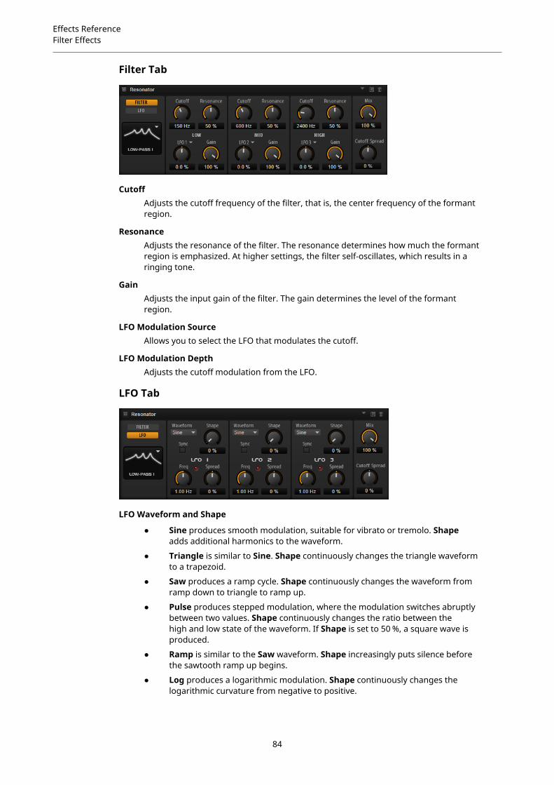
Effects ReferenceFilter Effects
Filter Tab
CutoffAdjusts the cutoff frequency of the filter, that is, the center frequency of the formantregion.
ResonanceAdjusts the resonance of the filter. The resonance determines how much the formantregion is emphasized. At higher settings, the filter self-oscillates, which results in aringing tone.
GainAdjusts the input gain of the filter. The gain determines the level of the formantregion.
LFO Modulation SourceAllows you to select the LFO that modulates the cutoff.
LFO Modulation DepthAdjusts the cutoff modulation from the LFO.
LFO Tab
LFO Waveform and Shape
● Sine produces smooth modulation, suitable for vibrato or tremolo. Shapeadds additional harmonics to the waveform.
● Triangle is similar to Sine. Shape continuously changes the triangle waveformto a trapezoid.
● Saw produces a ramp cycle. Shape continuously changes the waveform fromramp down to triangle to ramp up.
● Pulse produces stepped modulation, where the modulation switches abruptlybetween two values. Shape continuously changes the ratio between thehigh and low state of the waveform. If Shape is set to 50 %, a square wave isproduced.
● Ramp is similar to the Saw waveform. Shape increasingly puts silence beforethe sawtooth ramp up begins.
● Log produces a logarithmic modulation. Shape continuously changes thelogarithmic curvature from negative to positive.
84

Effects ReferenceFilter Effects
● S & H 1 produces randomly stepped modulation, where each step is different.Shape puts ramps between the steps and changes the S & H into a smoothrandom signal when fully turned right.
● S & H 2 is similar to S & H 1. The steps alternate between random high andlow values. Shape puts ramps between the steps and changes the S & H into asmooth random signal when fully turned right.
SpreadFor each channel of the effect, there is a separate LFO signal. This parameter spreadsthe phase of the LFO signals across the different channels.For example, if the effect is used in stereo, positive values shift the LFO phaseforward on the left channel and backward on the right channel.
SyncActivate this to set the Freq parameter in fractions of beats.
FreqDetermines the frequency of the cutoff modulation.
WahWahWahWah is a variable slope band-pass filter modeling the well-known analog pedal effect.
You can independently specify the frequency, width, and the gain for the low and high pedalpositions. The crossover point between the low and high pedal positions lies at 50.
PedalControls the filter frequency sweep.
Freq Low/Freq HighThese parameters determine the frequency of the filter for the low and high pedalpositions.
Width Low/Width HighThese parameters determine the width (resonance) of the filter for the low and highpedal positions.
Gain Low/Gain HighThese parameters determine the gain of the filter for the low and high pedalpositions.
SlopeHere, you can choose between two filter slope values: 6 dB or 12 dB.
85

Effects ReferenceDistortion Effects
Distortion Effects
AmplifierThis effect emulates the sound of an amplifier with speakers.
There are different amplifiers and speaker models you can combine.
Amp ModelDetermines the type of amplifier. The sound character of the overdrive changes withthe amplifier. To bypass the amplifier, select No Amp.
Speaker ModelDetermines the speaker model type. Each model colors the sound uniquely. Tobypass the model, select No Speaker.
DriveAdjusts the amount of overdrive.
BassAdjusts the tone color of the low frequencies.
MiddleAdjusts the tone color of the mid frequencies.
TrebleAdjusts the tone color of the high frequencies.
PresenceAdds brightness to the sound.
Low DampAttenuates the low frequencies of the speakers.
High DampAttenuates the high frequencies of the speakers.
Channel ModeDefines which output channels of the amplifier deliver a distorted signal. You can setit to L (Left), R (Right) or L/R (Both). When set to L or R, the other channel provides aclean signal.
OutputControls the output level of the amplifier.
86

Effects ReferenceDistortion Effects
DistortionThis effect offers the whole range of distortion, from low fidelity, digital distortion to high fidelity,analog sounding distortion. The available distortion types (Rate Red, Tube Drive, Hard Clip, andBit Red) can be freely combined.
In GainAdjusts the input level of the sound.
Rate Red (Rate Reduction)Rate reduction distorts the sound by means of aliasing. Enable the Rate Red optionto activate the control that adjusts the amount of aliasing. The lower the setting, themore aliasing is added.
Tube DriveAdds warm, tube-like distortion to the sound. Enable the Tube Drive option toactivate the control that adjusts the amount of distortion. The higher the setting, themore distortion is added.
Hard ClipAdds bright, transistor-like distortion to the sound. Enable the Hard Clip option toactivate the control that adjusts the amount of distortion. The higher the setting, themore distortion is added.
Bit Red (Bit Reduction)Bit reduction distorts the sound by means of quantization noise. Enable the Bit Redoption to activate the control that adjusts the amount of quantization noise. Thelower the setting, the more quantization noise is added.
Out GainAdjusts the output level of the sound.
MixSets the ratio between the dry and the wet signal.
VST AmpThis effect emulates the sound of an amplifier with speakers. There are different amplifiers andspeaker models you can combine.
Amp ModelSpecifies the amplifier type. The sound character of the overdrive changes with theamplifier. To bypass the amp modeling, select No Amplifier.
87
Effects ReferenceDistortion Effects
Speaker ModelSpecifies the speaker model type. Each model colors the sound uniquely. To bypassthe speaker modeling, select No Cabinet.
DriveAdjusts the amount of overdrive.
BassAdjusts the tone color of the low frequencies.
MiddleAdjusts the tone color of the mid frequencies.
TrebleAdjusts the tone color of the high frequencies.
PresenceAdjusts the brightness of the sound.
Mic TypeYou can choose between two microphone types. If this control is set to 0 %, a large-diaphragm condenser microphone is used. At 100 %, you get a dynamic microphone.Settings in between allow you to fade between the characteristics of these twomicrophones.
Microphone PositionHere, you can choose between seven positions to place the microphone. Thesepositions result from two different angles (center and edge) and three differentdistances from the speaker, as well as an additional center position at an evengreater distance from the speaker.
Channel ModeDetermines in which way the two input channels are distorted.
● L (Left) only distorts the left input channel. The right channel remains cleanand unprocessed.
● R (Right) only distorts the right input channel. The left channel remains cleanand unprocessed.
● L+R (Left + Right) sums the two input channels into a mono signal which isthen distorted.
● Stereo distorts the two input channels independently.
NOTE
The L and R modes allow you to cascade two VST Amp effects, that is, to use the firstone to processes the left channel and the second one to process the right channel atdifferent settings.
OutputControls the output level of the amplifier.
88
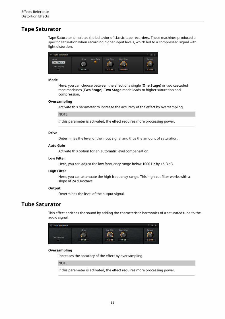
Effects ReferenceDistortion Effects
Tape SaturatorTape Saturator simulates the behavior of classic tape recorders. These machines produced aspecific saturation when recording higher input levels, which led to a compressed signal withlight distortion.
ModeHere, you can choose between the effect of a single (One Stage) or two cascadedtape machines (Two Stage). Two Stage mode leads to higher saturation andcompression.
OversamplingActivate this parameter to increase the accuracy of the effect by oversampling.
NOTE
If this parameter is activated, the effect requires more processing power.
DriveDetermines the level of the input signal and thus the amount of saturation.
Auto GainActivate this option for an automatic level compensation.
Low FilterHere, you can adjust the low frequency range below 1000 Hz by +/- 3 dB.
High FilterHere, you can attenuate the high frequency range. This high-cut filter works with aslope of 24 dB/octave.
OutputDetermines the level of the output signal.
Tube SaturatorThis effect enriches the sound by adding the characteristic harmonics of a saturated tube to theaudio signal.
OversamplingIncreases the accuracy of the effect by oversampling.
NOTE
If this parameter is activated, the effect requires more processing power.
89
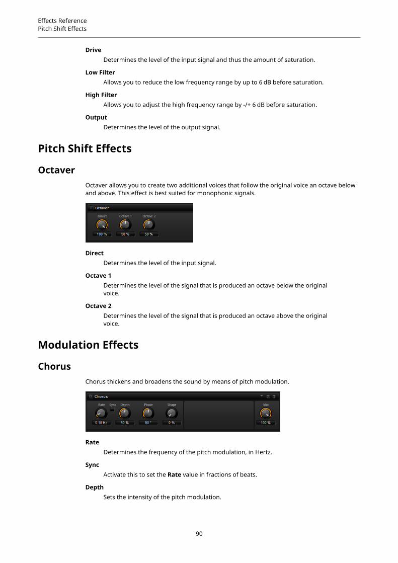
Effects ReferencePitch Shift Effects
DriveDetermines the level of the input signal and thus the amount of saturation.
Low FilterAllows you to reduce the low frequency range by up to 6 dB before saturation.
High FilterAllows you to adjust the high frequency range by -/+ 6 dB before saturation.
OutputDetermines the level of the output signal.
Pitch Shift Effects
OctaverOctaver allows you to create two additional voices that follow the original voice an octave belowand above. This effect is best suited for monophonic signals.
DirectDetermines the level of the input signal.
Octave 1Determines the level of the signal that is produced an octave below the originalvoice.
Octave 2Determines the level of the signal that is produced an octave above the originalvoice.
Modulation Effects
ChorusChorus thickens and broadens the sound by means of pitch modulation.
RateDetermines the frequency of the pitch modulation, in Hertz.
SyncActivate this to set the Rate value in fractions of beats.
DepthSets the intensity of the pitch modulation.
90

Effects ReferenceModulation Effects
PhaseWidens the sound image of the effect from mono to stereo.
ShapeAdjusts the characteristics of the modulation. At a setting of 0 %, the pitch changescontinuously, producing a steady modulation. At a setting of 100 %, the pitch doesnot change all the time, producing a less steady modulation.
MixSets the ratio between the dry and the wet signal.
FlangerThis effect thickens and broadens the sound by means of pitch modulation.
RateAllows you to specify the frequency of the pitch modulation in Hertz.
SyncActivate this to set the Rate value in fractions of beats.
DepthSets the intensity of the pitch modulation.
PhaseWidens the sound image of the effect from mono to stereo. This parameter alsochanges the characteristic of the Cross FB parameter.
ShapeAdjusts the characteristics of the modulation. You hear this best when Feedback isactivated. At a setting of 0 %, the sound sweeps linearly up and down. At a setting of100 %, the sound sweeps exponentially up and down.
MixSets the ratio between the dry and the wet signal.
FeedbackAdds resonances to the effect. This allows for jet-like sweeps of the sound.
Cross FBMixes the feedback of the left channel with the right channel, and vice versa. Theeffect of this parameter is influenced by the Phase parameter.
NOTE
This parameter only takes effect if the Feedback parameter is set to a value above0 %.
ToneAdjusts the tone color of the feedback. At lower values, the feedback is less bright.
91
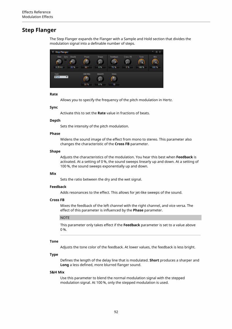
Effects ReferenceModulation Effects
Step FlangerThe Step Flanger expands the Flanger with a Sample and Hold section that divides themodulation signal into a definable number of steps.
RateAllows you to specify the frequency of the pitch modulation in Hertz.
SyncActivate this to set the Rate value in fractions of beats.
DepthSets the intensity of the pitch modulation.
PhaseWidens the sound image of the effect from mono to stereo. This parameter alsochanges the characteristic of the Cross FB parameter.
ShapeAdjusts the characteristics of the modulation. You hear this best when Feedback isactivated. At a setting of 0 %, the sound sweeps linearly up and down. At a setting of100 %, the sound sweeps exponentially up and down.
MixSets the ratio between the dry and the wet signal.
FeedbackAdds resonances to the effect. This allows for jet-like sweeps of the sound.
Cross FBMixes the feedback of the left channel with the right channel, and vice versa. Theeffect of this parameter is influenced by the Phase parameter.
NOTE
This parameter only takes effect if the Feedback parameter is set to a value above0 %.
ToneAdjusts the tone color of the feedback. At lower values, the feedback is less bright.
TypeDefines the length of the delay line that is modulated. Short produces a sharper andLong a less defined, more blurred flanger sound.
S&H MixUse this parameter to blend the normal modulation signal with the steppedmodulation signal. At 100 %, only the stepped modulation is used.
92

Effects ReferenceModulation Effects
SmoothUse this parameter to create ramps between the steps. This way, the steppedmodulation signal sounds smoother.
StepsDetermines into how many steps the modulation signal is divided. You can use up to32 steps.
PhaserThe Phaser effect thickens and broadens the sound by means of phase modulation.
RateSpecifies the frequency of the phase modulation.
SyncActivate this to set the Rate value in fractions of beats.
DepthSets the intensity of the phase modulation.
ShiftShifts the phase modulation upwards to higher frequencies of the spectrum.
PhaseWidens the sound image of the effect from mono to stereo.
FeedbackAdds resonances to the effect. Higher settings produce a more pronounced effect.
Low CutAttenuates the low frequencies.
High CutAttenuates the high frequencies.
MixSets the ratio between the dry and the wet signal.
TremoloThis effect produces amplitude modulation, that is, cyclic modulation of the level of the sound.
RateDetermines the frequency of the amplitude modulation.
SyncActivate this to set the Rate value in fractions of beats.
93
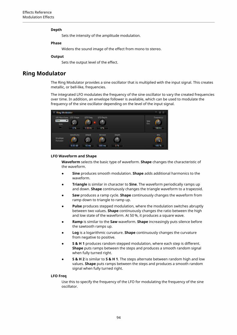
Effects ReferenceModulation Effects
DepthSets the intensity of the amplitude modulation.
PhaseWidens the sound image of the effect from mono to stereo.
OutputSets the output level of the effect.
Ring ModulatorThe Ring Modulator provides a sine oscillator that is multiplied with the input signal. This createsmetallic, or bell-like, frequencies.
The integrated LFO modulates the frequency of the sine oscillator to vary the created frequenciesover time. In addition, an envelope follower is available, which can be used to modulate thefrequency of the sine oscillator depending on the level of the input signal.
LFO Waveform and ShapeWaveform selects the basic type of waveform. Shape changes the characteristic ofthe waveform.
● Sine produces smooth modulation. Shape adds additional harmonics to thewaveform.
● Triangle is similar in character to Sine. The waveform periodically ramps upand down. Shape continuously changes the triangle waveform to a trapezoid.
● Saw produces a ramp cycle. Shape continuously changes the waveform fromramp down to triangle to ramp up.
● Pulse produces stepped modulation, where the modulation switches abruptlybetween two values. Shape continuously changes the ratio between the highand low state of the waveform. At 50 %, it produces a square wave.
● Ramp is similar to the Saw waveform. Shape increasingly puts silence beforethe sawtooth ramps up.
● Log is a logarithmic curvature. Shape continuously changes the curvaturefrom negative to positive.
● S & H 1 produces random stepped modulation, where each step is different.Shape puts ramps between the steps and produces a smooth random signalwhen fully turned right.
● S & H 2 is similar to S & H 1. The steps alternate between random high and lowvalues. Shape puts ramps between the steps and produces a smooth randomsignal when fully turned right.
LFO FreqUse this to specify the frequency of the LFO for modulating the frequency of the sineoscillator.
94

Effects ReferenceModulation Effects
SyncActivate this to set the LFO Freq value in fractions of beats.
LFO DepthSets the intensity of the LFO modulation of the sine oscillator frequency.
FrequencyDetermines the frequency of the sine oscillator.
MixSets the ratio between the dry and the wet signal.
Envelope FollowerThe Envelope Follower traces the input signal with an adjustable attack and releasetime and delivers a modulation signal representing the level envelope of the signal.
SensitivityAll input signals are mixed down to mono before they are sent to the EnvelopeFollower. The Sensitivity parameter sets the optimum input level for the EnvelopeFollower.
AttackThis adjusts the attack time, that is, the time the Envelope Follower needs toapproach increasing input levels.
ReleaseThis adjusts the release time, that is, the time the Envelope Follower needs toapproach decreasing input levels.
DepthDetermines the output level of the modulation signal of the Envelope Follower.
Frequency ShifterA frequency shifter shifts each frequency of the input signal by a fixed amount.
Unlike pitch shifters, where the frequencies are shifted by a factor, and where the harmonicrelations are kept, a frequency shifter alters the harmonic relations. Therefore, a largerfrequency shift usually results in a disharmonic sound.
Furthermore, a frequency shifter alters the frequencies by adding an offset, while a pitch shiftermultiplies the frequencies by a factor. The frequency shifter alters lower frequencies more thanhigher frequencies.
For example, if the input signal has the frequencies 100 Hz, 1000 Hz, and 10000 Hz, and you shiftthe frequency by +100 Hz, the resulting frequencies are 200 Hz, 1100 Hz, and 10100 Hz.
Freq CoarseHere you set the amount of frequency shift.
95

Effects ReferenceModulation Effects
Freq FineHere you can fine adjust the amount of frequency shift.
L/R Offset CoarseSets an offset for the left and right channels. Positive values shift the right channelupwards and the left channel downwards, and vice versa.
L/R Offset FineAllows for fine-adjustments of the offset between the left and right channels. Positivevalues shift the right channel upwards and the left channel downwards, and viceversa.
Mod CoarseSets the maximum amount of frequency shift via modulation from LFO and EnvelopeFollower.
Mod FineAllows for fine-adjustments to the amount of frequency shift via modulation fromLFO and Envelope Follower.
FeedbackSets the amount of feedback, that is, the amount of signal that is sent from theoutput of the effect back to its input. The sound is similar to that of a phaser. You cancontrol the direction and speed of this effect with the Frequency Fine parameter.
NotchesHere you set the number of notches the phaser effect produces when you use largeramounts of Feedback.
LFO Section
LFO Waveform and ShapeWaveform selects the basic type of waveform. Shape changes the characteristic ofthe waveform.
● Sine produces smooth modulation. Shape adds additional harmonics to thewaveform.
● Triangle is similar in character to Sine. The waveform periodically ramps upand down. Shape continuously changes the triangle waveform to a trapezoid.
● Saw produces a ramp cycle. Shape continuously changes the waveform fromramp down to triangle to ramp up.
● Pulse produces stepped modulation, where the modulation switches abruptlybetween two values. Shape continuously changes the ratio between the highand low state of the waveform. At 50 %, it produces a square wave.
● Ramp is similar to the Saw waveform. Shape increasingly puts silence beforethe sawtooth ramps up.
● Log is a logarithmic curvature. Shape continuously changes the curvaturefrom negative to positive.
● S & H 1 produces random stepped modulation, where each step is different.Shape puts ramps between the steps and produces a smooth random signalwhen fully turned right.
● S & H 2 is similar to S & H 1. The steps alternate between random high and lowvalues. Shape puts ramps between the steps and produces a smooth randomsignal when fully turned right.
FreqSpecifies the frequency of the LFO in Hertz.
96
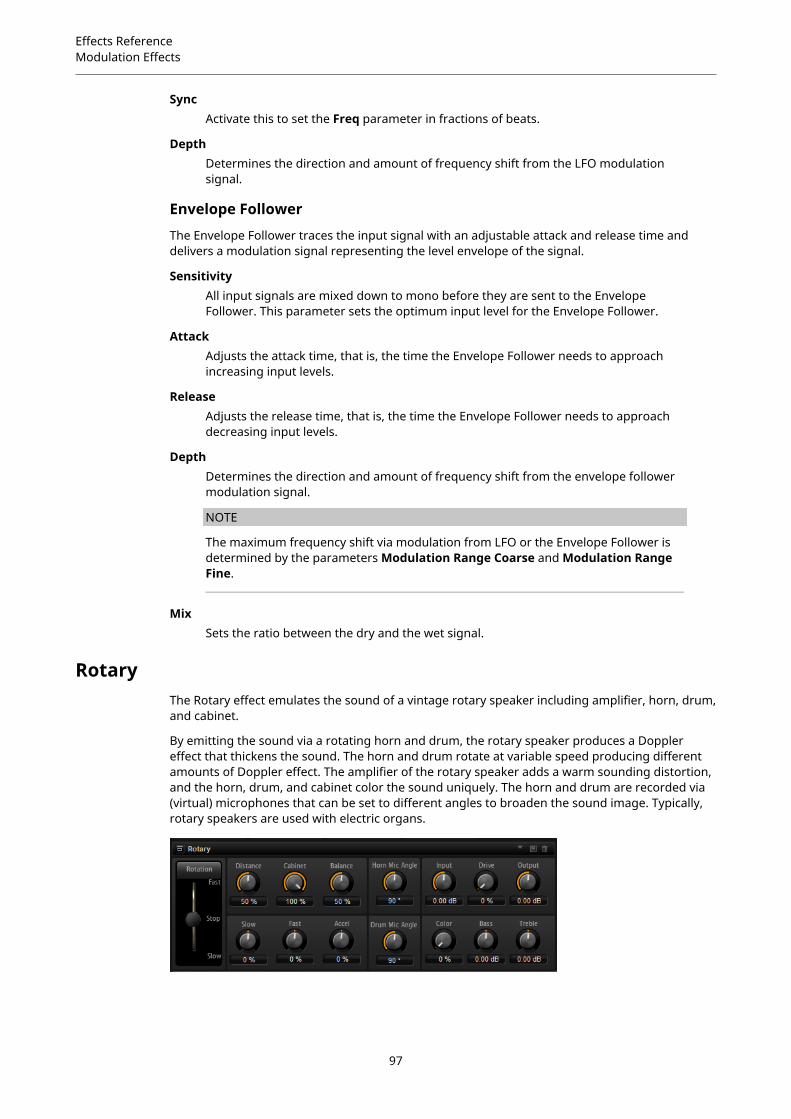
Effects ReferenceModulation Effects
SyncActivate this to set the Freq parameter in fractions of beats.
DepthDetermines the direction and amount of frequency shift from the LFO modulationsignal.
Envelope Follower
The Envelope Follower traces the input signal with an adjustable attack and release time anddelivers a modulation signal representing the level envelope of the signal.
SensitivityAll input signals are mixed down to mono before they are sent to the EnvelopeFollower. This parameter sets the optimum input level for the Envelope Follower.
AttackAdjusts the attack time, that is, the time the Envelope Follower needs to approachincreasing input levels.
ReleaseAdjusts the release time, that is, the time the Envelope Follower needs to approachdecreasing input levels.
DepthDetermines the direction and amount of frequency shift from the envelope followermodulation signal.
NOTE
The maximum frequency shift via modulation from LFO or the Envelope Follower isdetermined by the parameters Modulation Range Coarse and Modulation RangeFine.
MixSets the ratio between the dry and the wet signal.
RotaryThe Rotary effect emulates the sound of a vintage rotary speaker including amplifier, horn, drum,and cabinet.
By emitting the sound via a rotating horn and drum, the rotary speaker produces a Dopplereffect that thickens the sound. The horn and drum rotate at variable speed producing differentamounts of Doppler effect. The amplifier of the rotary speaker adds a warm sounding distortion,and the horn, drum, and cabinet color the sound uniquely. The horn and drum are recorded via(virtual) microphones that can be set to different angles to broaden the sound image. Typically,rotary speakers are used with electric organs.
97
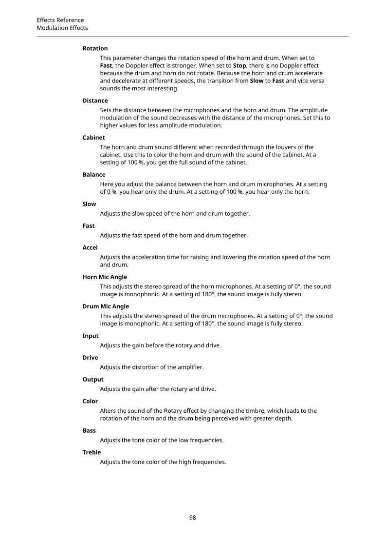
Effects ReferenceModulation Effects
RotationThis parameter changes the rotation speed of the horn and drum. When set toFast, the Doppler effect is stronger. When set to Stop, there is no Doppler effectbecause the drum and horn do not rotate. Because the horn and drum accelerateand decelerate at different speeds, the transition from Slow to Fast and vice versasounds the most interesting.
DistanceSets the distance between the microphones and the horn and drum. The amplitudemodulation of the sound decreases with the distance of the microphones. Set this tohigher values for less amplitude modulation.
CabinetThe horn and drum sound different when recorded through the louvers of thecabinet. Use this to color the horn and drum with the sound of the cabinet. At asetting of 100 %, you get the full sound of the cabinet.
BalanceHere you adjust the balance between the horn and drum microphones. At a settingof 0 %, you hear only the drum. At a setting of 100 %, you hear only the horn.
SlowAdjusts the slow speed of the horn and drum together.
FastAdjusts the fast speed of the horn and drum together.
AccelAdjusts the acceleration time for raising and lowering the rotation speed of the hornand drum.
Horn Mic AngleThis adjusts the stereo spread of the horn microphones. At a setting of 0°, the soundimage is monophonic. At a setting of 180°, the sound image is fully stereo.
Drum Mic AngleThis adjusts the stereo spread of the drum microphones. At a setting of 0°, the soundimage is monophonic. At a setting of 180°, the sound image is fully stereo.
InputAdjusts the gain before the rotary and drive.
DriveAdjusts the distortion of the amplifier.
OutputAdjusts the gain after the rotary and drive.
ColorAlters the sound of the Rotary effect by changing the timbre, which leads to therotation of the horn and the drum being perceived with greater depth.
BassAdjusts the tone color of the low frequencies.
TrebleAdjusts the tone color of the high frequencies.
98
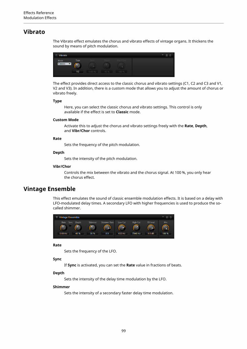
Effects ReferenceModulation Effects
VibratoThe Vibrato effect emulates the chorus and vibrato effects of vintage organs. It thickens thesound by means of pitch modulation.
The effect provides direct access to the classic chorus and vibrato settings (C1, C2 and C3 and V1,V2 and V3). In addition, there is a custom mode that allows you to adjust the amount of chorus orvibrato freely.
TypeHere, you can select the classic chorus and vibrato settings. This control is onlyavailable if the effect is set to Classic mode.
Custom ModeActivate this to adjust the chorus and vibrato settings freely with the Rate, Depth,and Vibr/Chor controls.
RateSets the frequency of the pitch modulation.
DepthSets the intensity of the pitch modulation.
Vibr/ChorControls the mix between the vibrato and the chorus signal. At 100 %, you only hearthe chorus effect.
Vintage EnsembleThis effect emulates the sound of classic ensemble modulation effects. It is based on a delay withLFO-modulated delay times. A secondary LFO with higher frequencies is used to produce the so-called shimmer.
RateSets the frequency of the LFO.
SyncIf Sync is activated, you can set the Rate value in fractions of beats.
DepthSets the intensity of the delay time modulation by the LFO.
ShimmerSets the intensity of a secondary faster delay time modulation.
99
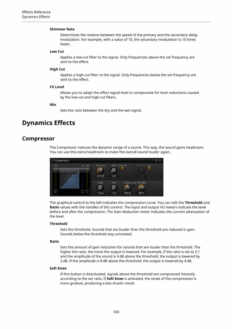
Effects ReferenceDynamics Effects
Shimmer RateDetermines the relation between the speed of the primary and the secondary delaymodulation. For example, with a value of 10, the secondary modulation is 10 timesfaster.
Low CutApplies a low-cut filter to the signal. Only frequencies above the set frequency aresent to the effect.
High CutApplies a high-cut filter to the signal. Only frequencies below the set frequency aresent to the effect.
FX LevelAllows you to adapt the effect signal level to compensate for level reductions causedby the low-cut and high-cut filters.
MixSets the ratio between the dry and the wet signal.
Dynamics Effects
CompressorThe Compressor reduces the dynamic range of a sound. This way, the sound gains headroom.You can use this extra headroom to make the overall sound louder again.
The graphical control to the left indicates the compression curve. You can edit the Threshold andRatio values with the handles of this control. The input and output VU meters indicate the levelbefore and after the compression. The Gain Reduction meter indicates the current attenuation ofthe level.
ThresholdSets the threshold. Sounds that are louder than the threshold are reduced in gain.Sounds below the threshold stay untreated.
RatioSets the amount of gain reduction for sounds that are louder than the threshold. Thehigher the ratio, the more the output is lowered. For example, if the ratio is set to 2:1and the amplitude of the sound is 4 dB above the threshold, the output is lowered by2 dB. If the amplitude is 8 dB above the threshold, the output is lowered by 4 dB.
Soft KneeIf this button is deactivated, signals above the threshold are compressed instantlyaccording to the set ratio. If Soft Knee is activated, the onset of the compression ismore gradual, producing a less drastic result.
100

Effects ReferenceDynamics Effects
Make-UpRaises the overall sound. This can become necessary if too much gain reduction isintroduced by the Threshold and Ratio parameters. You can see the amount of gainreduction in the Gain Reduction meter.
NOTE
This parameter is not available if the Auto button is activated.
Auto Make-Up GainSets the Make-Up value automatically, depending on the current Threshold andRatio settings.
AttackDetermines how fast the Compressor reacts to sounds that exceed the threshold.The longer the attack time, the longer the time it takes to reduce the gain. Withlonger attack times, the onset of sounds exceeding the threshold pass throughunprocessed.
HoldSets the time period during which the compression is applied after the soundexceeds the set threshold.
ReleaseDetermines how fast the Compressor effect reacts to sounds that fall below the setthreshold. The longer the release time, the longer it takes to return to the originallevel.
NOTE
This parameter is not available if the Auto Release button is activated.
Auto ReleaseActivate this to set the release time automatically. The Compressor analyzes theinput sound continuously to find the optimal setting.
Peak/RMSDetermines whether the input signal is analyzed according to peak or RMS values ora mixture of both. At a setting of 0 %, the Compressor uses Peak sensing only and at100 %, RMS sensing only. Peak means that the Compressor directly senses the peaklevel of the sound. RMS means that the Compressor senses the average power of thesound. Peak sensing responds faster than RMS sensing. Typically, Peak sensing isused for transient and RMS sensing for sustained sounds.
LiveIf this button is activated, the look-ahead feature of the effect is disengaged. Look-ahead produces more accurate processing, but adds a certain amount of latencyas a trade-off. If Live mode is activated, there is no latency, which is better for liveprocessing.
Vintage CompressorVintage Compressor is modeled after vintage type compressors.
This compressor features separate controls for Input and Output gain, Attack, and Release. Inaddition, there is a Punch mode which preserves the attack phase of the signal and a program-dependent Auto feature for the Release parameter.
101
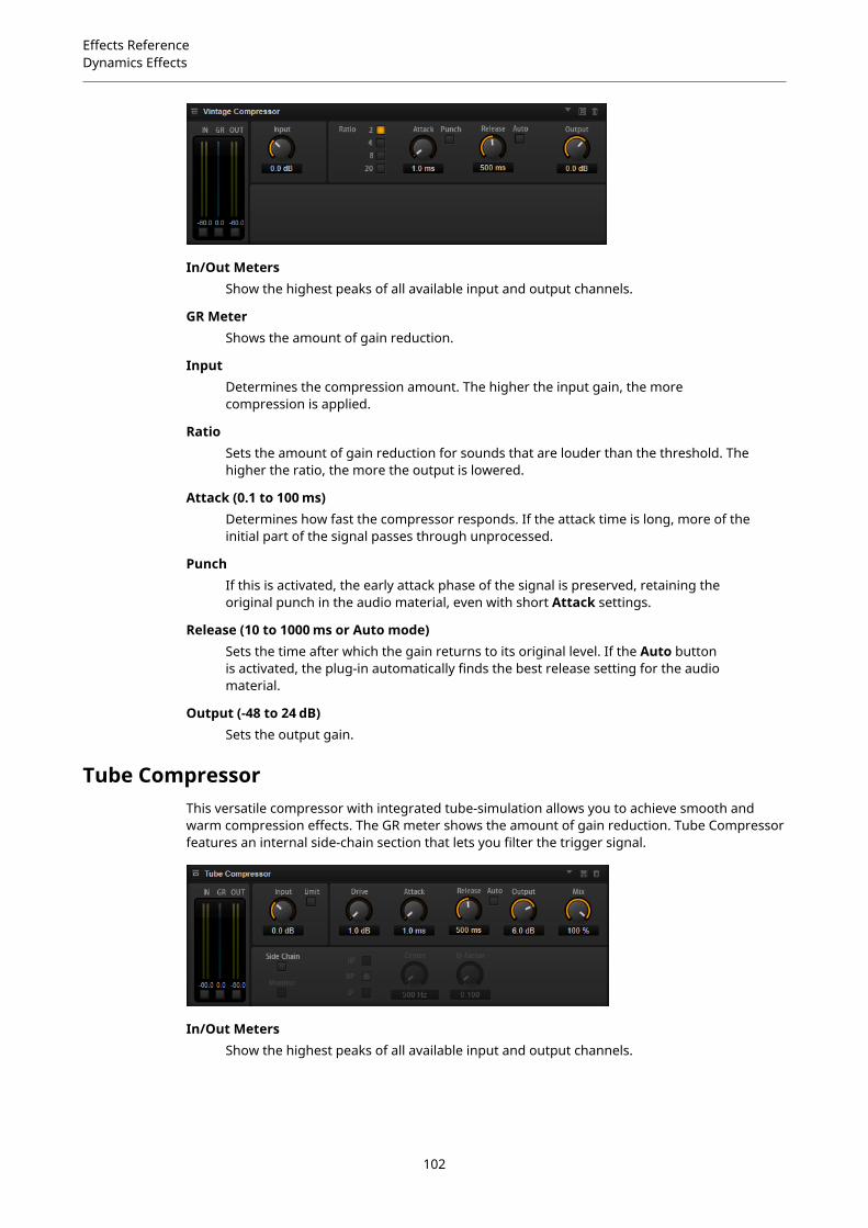
Effects ReferenceDynamics Effects
In/Out MetersShow the highest peaks of all available input and output channels.
GR MeterShows the amount of gain reduction.
InputDetermines the compression amount. The higher the input gain, the morecompression is applied.
RatioSets the amount of gain reduction for sounds that are louder than the threshold. Thehigher the ratio, the more the output is lowered.
Attack (0.1 to 100 ms)Determines how fast the compressor responds. If the attack time is long, more of theinitial part of the signal passes through unprocessed.
PunchIf this is activated, the early attack phase of the signal is preserved, retaining theoriginal punch in the audio material, even with short Attack settings.
Release (10 to 1000 ms or Auto mode)Sets the time after which the gain returns to its original level. If the Auto buttonis activated, the plug-in automatically finds the best release setting for the audiomaterial.
Output (-48 to 24 dB)Sets the output gain.
Tube CompressorThis versatile compressor with integrated tube-simulation allows you to achieve smooth andwarm compression effects. The GR meter shows the amount of gain reduction. Tube Compressorfeatures an internal side-chain section that lets you filter the trigger signal.
In/Out MetersShow the highest peaks of all available input and output channels.
102
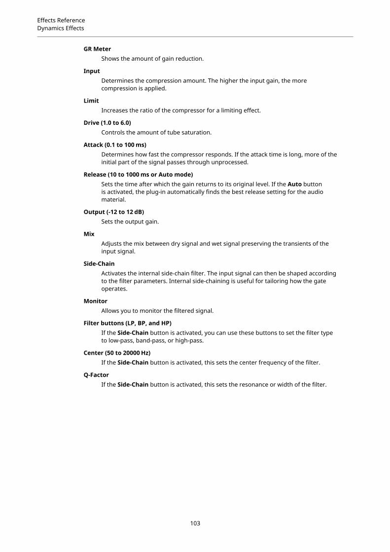
Effects ReferenceDynamics Effects
GR MeterShows the amount of gain reduction.
InputDetermines the compression amount. The higher the input gain, the morecompression is applied.
LimitIncreases the ratio of the compressor for a limiting effect.
Drive (1.0 to 6.0)Controls the amount of tube saturation.
Attack (0.1 to 100 ms)Determines how fast the compressor responds. If the attack time is long, more of theinitial part of the signal passes through unprocessed.
Release (10 to 1000 ms or Auto mode)Sets the time after which the gain returns to its original level. If the Auto buttonis activated, the plug-in automatically finds the best release setting for the audiomaterial.
Output (-12 to 12 dB)Sets the output gain.
MixAdjusts the mix between dry signal and wet signal preserving the transients of theinput signal.
Side-ChainActivates the internal side-chain filter. The input signal can then be shaped accordingto the filter parameters. Internal side-chaining is useful for tailoring how the gateoperates.
MonitorAllows you to monitor the filtered signal.
Filter buttons (LP, BP, and HP)If the Side-Chain button is activated, you can use these buttons to set the filter typeto low-pass, band-pass, or high-pass.
Center (50 to 20000 Hz)If the Side-Chain button is activated, this sets the center frequency of the filter.
Q-FactorIf the Side-Chain button is activated, this sets the resonance or width of the filter.
103

Effects ReferenceDynamics Effects
LimiterThe Limiter effect prevents the sound from exceeding the set output level. This can be used toavoid clipping in following effects, for example.
The input and output meters indicate the level before and after the Limiter. The Gain Reductionmeter in the middle indicates the current attenuation of the level.
InputAdjusts the input level of the sound. By increasing the input level, you can drive thesound more and more into limiting.
OutputSets the maximum output level of the sound.
ReleaseSets the time that the gain needs to return to its original level. The longer the releasetime, the longer it takes to return to the original level.
NOTE
This parameter is not available if the Auto button is activated.
AutoActivate this to set the release time automatically. The Limiter analyzes the inputsound continuously to find the optimal setting.
Brickwall LimiterBrickwall Limiter ensures that the output level never exceeds a set limit.
Due to its fast attack time, Brickwall Limiter can reduce even short audio level peaks withoutcreating audible artifacts. However, this plug-in creates a latency of 1 ms. Brickwall Limiterfeatures separate meters for input, output, and the amount of limiting.
Threshold (-20 to 0 dB)Determines the level where the limiter kicks in. Only signal levels above the setthreshold are processed.
104

Effects ReferenceDynamics Effects
Release (ms or Auto mode)Sets the time after which the gain returns to the original level when the signal dropsbelow the threshold. If the Auto button is activated, the plug-in automatically findsthe best release setting for the audio material.
LinkIf this button is activated, Brickwall Limiter uses the channel with the highest levelto analyze the input signal. If the button is deactivated, each channel is analyzedseparately.
Detect Intersample ClippingIf this option is activated, Brickwall Limiter uses oversampling to detect and limitsignal levels between two samples to prevent distortion when converting digitalsignals into analog signals.
NOTE
Brickwall Limiter is designed for the reduction of occasional peaks in the signal. If the GainReduction meter indicates constant limiting, try raising the threshold or lowering the overall levelof the input signal.
MaximizerThis plug-in raises the loudness of audio material without the risk of clipping.
OptimizeDetermines the loudness of the signal.
OutputSets the maximum output level.
Soft ClipIf this button is activated, Maximizer starts limiting or clipping the signal softly. At thesame time, harmonics are generated, adding a warm, tube-like characteristic to theaudio material.
ExpanderThe Expander reduces the output level in relation to the input level for signals below the setthreshold. This is useful to enhance the dynamic range or reduce the noise in quiet passages.
105

Effects ReferenceDynamics Effects
The graphical control to the left shows the expansion curve. You can edit the Threshold andRatio values with the handles of this control. The input and output meters indicate the levelbefore and after the expansion. The Gain Reduction meter indicates the current attenuation ofthe level.
ThresholdSets the threshold. Sounds that are softer than the threshold are reduced in gain.Sounds above the threshold stay untreated.
RatioSets the amount of gain reduction for sounds that are softer than the threshold. Thehigher the ratio, the more the output is lowered. For example, if the ratio is set to 2:1and the amplitude of the sound is 4 dB below the threshold, the output is lowered by2 dB. If the amplitude is 8 dB below the threshold, the output is lowered by 4 dB.
Soft KneeIf this button is deactivated, signals above the threshold are compressed instantlyaccording to the set ratio. When Soft Knee is activated, the onset of the expansion ismore gradual, producing a less drastic result.
AttackDetermines how fast the Expander reduces the gain when the sound falls below theset threshold. The longer the attack time, the longer it takes to reduce the gain.
HoldSets the time period during which the expansion is applied after the sound fallsbelow the set threshold.
ReleaseDetermines how fast the Expander effect raises the gain after the sound exceeds theset threshold. The longer the release time, the longer it takes to raise the gain.
NOTE
This parameter is not available when the Auto Release button is activated.
AutoActivate this to set the release time automatically. The Expander analyzes the inputsound continuously to find the optimal setting.
Peak/RMSDetermines whether the input signal is analyzed according to peak or RMS valuesor a mixture of both. At a setting of 0 %, the Expander uses Peak sensing only andat 100 %, RMS sensing only. Peak means that the Expander directly senses the peaklevel of the sound. RMS means that the Expander senses the average power of thesound. Peak sensing responds faster than RMS sensing. Typically, Peak sensing isused for transient and RMS sensing for sustained sounds.
LiveIf this button is activated, the look-ahead feature of the effect is disengaged. Look-ahead produces more accurate processing, but adds a certain amount of latencyas a trade-off. If Live mode is activated, there is no latency, which is better for liveprocessing.
106

Effects ReferenceDynamics Effects
GateThe Gate effect passes sound only to its output if the input sound exceeds the set threshold.Sounds below the threshold are silenced.
An internal side-chain filter allows you to analyze a filtered version of the input sound instead.This way, the gate detects only certain frequencies of the input sound.
ThresholdDetermines the level that activates the gate. Signal levels above the set thresholdtrigger the gate to open, and signal levels below the set threshold close the gate.
FilterActivates the internal side-chain filter. If this button is activated, the input soundis filtered before it is analyzed. The gate opens only if the filtered sound exceedsthe set threshold. When the Filter button is deactivated, the filter controls are notavailable.
Filter TypeSets the filter type for the side-chain filter. Select high-pass (HP) to detect highfrequencies, band-pass (BP) to detect mid frequencies, and low-pass (LP) to detectlow frequencies only.
MonitorActivate this button to listen to the sound of the side-chain filter. The gate is inactivewhen the Monitor button is activated.
CenterSets the center frequency of the side-chain filter.
Q-FactorAdjusts the bandwidth of the filter from wide to narrow.
AttackDetermines how fast the gate opens when the sound exceeds the set threshold. Thelonger the attack time, the longer it takes for the sound to fade in.
HoldSets the time period during which the gate is applied after the sound falls below theset threshold.
ReleaseDetermines how fast the gate closes after the sound falls below the set threshold.The longer the release time, the longer it takes for the sound to fade out.
NOTE
This parameter is not available when the Auto button is activated.
107
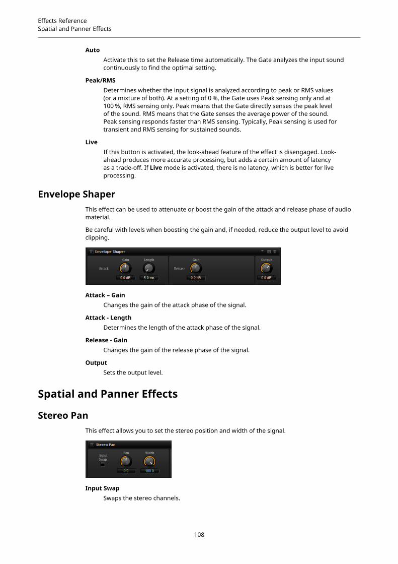
Effects ReferenceSpatial and Panner Effects
AutoActivate this to set the Release time automatically. The Gate analyzes the input soundcontinuously to find the optimal setting.
Peak/RMSDetermines whether the input signal is analyzed according to peak or RMS values(or a mixture of both). At a setting of 0 %, the Gate uses Peak sensing only and at100 %, RMS sensing only. Peak means that the Gate directly senses the peak levelof the sound. RMS means that the Gate senses the average power of the sound.Peak sensing responds faster than RMS sensing. Typically, Peak sensing is used fortransient and RMS sensing for sustained sounds.
LiveIf this button is activated, the look-ahead feature of the effect is disengaged. Look-ahead produces more accurate processing, but adds a certain amount of latencyas a trade-off. If Live mode is activated, there is no latency, which is better for liveprocessing.
Envelope ShaperThis effect can be used to attenuate or boost the gain of the attack and release phase of audiomaterial.
Be careful with levels when boosting the gain and, if needed, reduce the output level to avoidclipping.
Attack – GainChanges the gain of the attack phase of the signal.
Attack - LengthDetermines the length of the attack phase of the signal.
Release - GainChanges the gain of the release phase of the signal.
OutputSets the output level.
Spatial and Panner Effects
Stereo PanThis effect allows you to set the stereo position and width of the signal.
Input SwapSwaps the stereo channels.
108

Effects ReferenceLegacy Effects
PanSets the pan position of the signal. The panning is available for mono and stereoinput signals.
WidthAdjusts the stereo width of the signal from stereo to mono.
Stereo EnhancerThis plug-in expands the stereo width of (stereo) audio material. It cannot be used with monofiles.
WidthControls the width or depth of the stereo enhancement. Turn clockwise to increasethe enhancement.
DelayIncreases the amount of differences between the left and right channels to furtherincrease the stereo effect.
ColorGenerates additional differences between the channels to increase the stereoenhancement.
MonoSwitches the output to mono, to check for possible unwanted coloring of the soundwhich sometimes can occur when enhancing the stereo image.
Legacy Effects
HALion 3 Legacy EffectsIn addition to the standard effects, a number of effects from HALion 3 is also provided. Theseeffects can be selected from the Legacy submenu of the effects menu.
Hall Reverb
A simple reverb with adjustable pre-delay and damping.
PreDelayDelays the wet signal to simulate larger acoustic spaces or to create a slap-backeffect.
TimeLength of reverb tail.
DampProgressive damping of high frequencies.
Low EQLow-cut EQ.
High EQHigh-cut EQ.
MixWet/dry mix.
109

Effects ReferenceLegacy Effects
Non-Linear Reverb
A gated reverb with a sharp cutoff.
TimeLength of reverb tail. It also allows you to change the sound from dense earlyreflections to a trashy, grainy 1980’s-type reverb.
Low EQLow-cut EQ.
High EQHigh-cut EQ.
MixWet/dry mix.
Early Reflections
A short, dense reverb for simulating small acoustic spaces and to thicken or blur sounds.
TimeLength of reverb tail. It also allows you to change the sound from dense earlyreflections to a trashy, grainy 80’s-type reverb.
Low EQLow-cut EQ.
High EQHigh-cut EQ.
MixWet/dry mix.
Delay
A simple mono-in/stereo-out delay.
TimeDelay time.
SyncIf Sync is activated, you can set the delay time in fractions of beats.
FeedbackControls the number of delay repeats.
BalanceRatio of left delay time to right delay time.
DampHigh-cut filter to soften delay repeats.
Stereo Delay
A stereo-in/stereo-out delay.
TimeDelay time.
110

Effects ReferenceLegacy Effects
FeedbackControls the number of delay repeats. For minimum feedback, set the slider to themid position. By moving the slider to the left or right, cross delay is applied, whereleft output feeds back into right input or vice versa.
SyncIf Sync is activated, you can set the delay time in fractions of beats.
BalanceRatio of left delay time to right delay time.
DampHigh-cut filter to soften delay repeats.
Long Delay
This effect provides the same parameter set as the Delay effect, except that longer delays of upto four seconds can be set.
Tape Delay
Simulation of a vintage 4-head analog tape delay.
TimeDelay time.
SyncIf Sync is activated, you can set the delay time in fractions of beats.
FeedbackControls the number of delay repeats.
VintageAmount of vintage color and tape flutter.
MixWet/dry mix.
Head 1Delay level 1 (the output is panned left).
Head 2Delay level 2 (the output is panned right).
Head 3Delay level 3.
Head 4Delay level 4.
Pan 3+4Varies the panning of delays 3 and 4 from center to hard left/right.
Vol 3+4Varies the volume of delay outputs 3 and 4.
Chorus
A straightforward chorus effect that can be used to widen sounds.
111

Effects ReferenceLegacy Effects
RateThe modulation rate.
DepthThe amount of pitch modulation.
PreDelayThe initial delay, to vary the tightness of the chorused voices in relation to the drysignal.
MixWet/dry mix.
Ensemble
Chorus with a more complex modulation waveform for a lively thickening effect.
RateThe modulation rate.
DepthThe amount of pitch modulation.
ShimmerCreates a more complex modulation effect.
WidthStereo width adjustment.
MixWet/dry mix.
Flanger
A classic flanger effect.
RateSweep rate.
DepthSweep depth.
FeedbackFeedback amount. Increase for a more intense flanging effect.
PreDelayInitial delay. Adjusts the minimum delay time/maximum flange frequency.
MixWet/dry mix.
Phaser
A four pole phaser for subtle phasing effects.
RateSweep rate.
DepthSweep depth.
112

Effects ReferenceLegacy Effects
FeedbackFeedback amount. Increase for a more pronounced effect.
StereoOffset between left and right modulation.
CenterSets the center frequency around which the modulation occurs.
MixWet/dry mix.
Pan & Tremolo
Autopan and Tremolo effect as used in vintage electric pianos.
RateSweep rate.
PhaseRelative phase of left and right channel amplitude modulation, to vary from tremoloto autopan.
ShapeShape of modulation waveform from thin pulse, through sine, to fat pulse.
MixWet/dry mix.
Stereo Width
A stereo width enhancer with 4 modes.
Mode
● Adjust mode adjusts the existing width of the stereo signal.
● Swap mode adjusts the existing width of the stereo signal and additionallyswaps the left and right channels.
● Comb mode applies a stereo comb filter effect.
● Haas mode synthesizes the stereo width by delaying one channel.
DelayDelay time (not used in Adjust and Swap modes).
WidthOverall width adjustment.
Low/Mid/HighWidth adjustment for the low, mid, and high frequencies.
OutputOutput level trim.
Rotary Speaker
Simulation of a rotary speaker cabinet with high and low rotors.
RateMaster speed control: Stop, Slow, Fast.
113

Effects ReferenceLegacy Effects
DirtAmount of overdrive.
LoHiCrossover frequency between low and high rotors.
WidthStereo width.
ToneAdjusts the tone of the overdriven signal.
Low/High SpeedSpeed of the high and low rotors.
Low/High AccelerationAcceleration of the high and low rotors.
MixWet/dry mix.
Wah Pedal
An auto-wah effect.
RateModulation rate.
DepthModulation depth.
PedalAdjusts the filter frequency.
Mode
● Auto Wah: Envelope controlled wah effect.
● Pedal Wah: No modulation. The Pedal parameter sets the frequency.
● Mod Wah: LFO modulation. The Rate parameter controls the modulation rate.
ResonanceSets the amount of filter resonance.
TrackingAdjusts the envelope tracking speed in Auto mode, and the envelope ratemodulation in Mod mode.
MixWet/dry mix.
TalkBox
Modulated vowel formant filter.
RateLFO modulation rate.
DepthLFO modulation depth.
114

Effects ReferenceLegacy Effects
VowelIn center setting, vowels are produced when there is no modulation.
Env ModAmount of vowel modulation by input signal level.
Env AttRate of response to a rising input signal level.
Env RelRate of response to a falling input signal level.
MixWet/dry mix.
Shelf EQ
Simple tone control.
OutputOutput level trim.
BassLow frequency cut/boost.
TrebleHigh frequency cut/boost.
Parametric EQ
Two-band parametric equalizer.
Gain 1/2Cut/boost amount for the two bands.
Freq 1/2Sets the center frequency for the two bands.
Width 1/2Sets the bandwidth for the two bands (Q).
OutputOutput level trim.
Enhancer
Psycho acoustic spectrum shaping.
High DepthHigh frequency boost, combined with mid cut.
High TuneHigh/mid tune.
Low DepthLow frequency boost.
Low TuneLow frequency tune.
115
Effects ReferenceLegacy Effects
Limiter
Hard level limiting.
DriveInput signal drive.
AttackAttack time.
ReleaseRelease time.
OutputOutput level trim.
Compressor
A simple compressor effect.
ThresholdCompression threshold.
RatioCompression amount.
AttackAttack time.
ReleaseRelease time.
OutputOutput level trim.
Multiband
Three-band compressor.
DriveInput signal drive (increase for more density).
Lo/HiBalance of low and high frequency bands.
MidLevel of mid frequency band.
AttackAttack time.
ReleaseRelease time.
OutputOutput level trim.
Gate
Simple gate effect.
116

Effects ReferenceLegacy Effects
ThresholdGate threshold.
RangeLevel reduction when gate closed.
AttackAttack time.
ReleaseRelease time.
OutputOutput level trim.
Distortion
Hard clipping distortion.
DriveDistortion amount.
BiasAdjusts the balance between even and odd harmonics, that is, the character of thedistortion.
ToneDistortion tone.
OutOutput level trim.
MixWet/dry mix.
Overdrive
Softer distortion with a gradual onset.
DriveOverdrive amount.
BiasOverdrive character. Adjusts the balance between even and odd harmonics.
OutOutput level trim.
MixWet/dry mix.
Bit Reduction
Digital, lo-fi, quality degradation.
ModeDetermines whether the bit depth is fixed (Linear) or depends on the signal level(Companding).
RateSimulated sample rate.
117

Effects ReferenceLegacy Effects
DepthSample bit depth.
Slew RateMaximum rate of change of output waveform, for a soft, wooly distortion.
MixWet/dry mix.
Amp Simulator
Amplifier modeling effect.
ModelThe type of amplifier model. This changes the tone character.
ModeMono/Stereo operation. Mono saves CPU, and in some cases sounds more solid.
DriveOverdrive amount.
FeedbackFeedback amount. The result depends on the input signal.
TrebleTreble boost. Optionally in or out of phase for different tones.
MixWet/dry mix.
Modulate L/R
This effect features three modes of signal distortion, where one side of a stereo signal is used tomodulate the other.
Mode
● Ring Mod: Ring modulation.
● Env Mod: The signal level of the right channel is modulated by the level of theleft channel.
● Duck: The signal level of the right channel is reduced when the level of the leftchannel increases.
ThruDefines which input signals are used as the dry signal for the Mix.
SmoothSmoothing of modulation.
DriveLevel trim.
MixWet/dry mix.
118

Using the Standalone Versionof the Plug-In
If you use HALion Sonic SE as a standalone application, an additional section is available at thetop of the control panel. Here, you can define key commands, set up audio and MIDI interfaceroutings, adjust the master volume, and access the integrated MIDI scratch pad, which allowsyou to record your musical ideas without having to start a MIDI sequencer application. It can alsobe used to play multitrack arrangements that trigger the different programs.
Making Preferences SettingsYou can configure the standalone version of HALion Sonic SE in the Plug-In Preferences dialog.
● To open the Plug-In Preferences dialog, click the Open Preferences button to theright of the audio output field or right-click in the topmost section of the control panel andselect Plug-In Preferences on the context menu.
Preferences DialogThe Plug-In Preferences dialog has several pages on which you can make settings.
MIDI Page
MIDI Input PortsUse this pop-up menu to specify a MIDI input.
Channel FilterDetermines whether MIDI events are recorded on all MIDI channels, or only on onespecific channel.
Filter ‘All Notes Off’ ControllerActivate this parameter to avoid unwanted “All Notes Off” messages. Such messagesare sent by some keyboards when the last key is released. This causes HALion SonicSE to stop playback, even when the sustain pedal is still in use.
Outputs Page
You can use the Audio Output Ports pop-up menus to assign different audio outputs. You canassign different audio outputs for each channel.
● To map an output to a channel, select it from the pop-up menu.
● To set the front and rear channels to incrementing audio output ports, hold down Shiftand select an audio output.
● To assign the audio outputs in pairs to the front and rear channels, hold down Alt-Shiftand select an audio output.
119
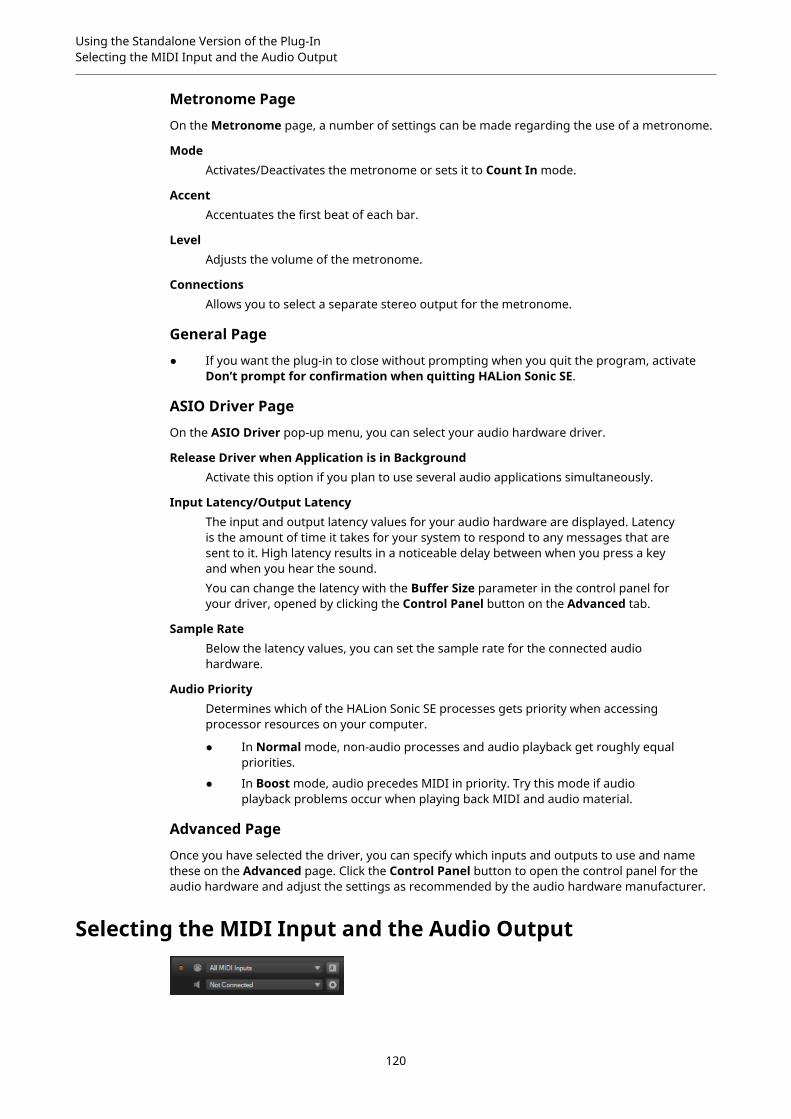
Using the Standalone Version of the Plug-InSelecting the MIDI Input and the Audio Output
Metronome Page
On the Metronome page, a number of settings can be made regarding the use of a metronome.
ModeActivates/Deactivates the metronome or sets it to Count In mode.
AccentAccentuates the first beat of each bar.
LevelAdjusts the volume of the metronome.
ConnectionsAllows you to select a separate stereo output for the metronome.
General Page
● If you want the plug-in to close without prompting when you quit the program, activateDon’t prompt for confirmation when quitting HALion Sonic SE.
ASIO Driver Page
On the ASIO Driver pop-up menu, you can select your audio hardware driver.
Release Driver when Application is in BackgroundActivate this option if you plan to use several audio applications simultaneously.
Input Latency/Output LatencyThe input and output latency values for your audio hardware are displayed. Latencyis the amount of time it takes for your system to respond to any messages that aresent to it. High latency results in a noticeable delay between when you press a keyand when you hear the sound.You can change the latency with the Buffer Size parameter in the control panel foryour driver, opened by clicking the Control Panel button on the Advanced tab.
Sample RateBelow the latency values, you can set the sample rate for the connected audiohardware.
Audio PriorityDetermines which of the HALion Sonic SE processes gets priority when accessingprocessor resources on your computer.
● In Normal mode, non-audio processes and audio playback get roughly equalpriorities.
● In Boost mode, audio precedes MIDI in priority. Try this mode if audioplayback problems occur when playing back MIDI and audio material.
Advanced Page
Once you have selected the driver, you can specify which inputs and outputs to use and namethese on the Advanced page. Click the Control Panel button to open the control panel for theaudio hardware and adjust the settings as recommended by the audio hardware manufacturer.
Selecting the MIDI Input and the Audio Output
120
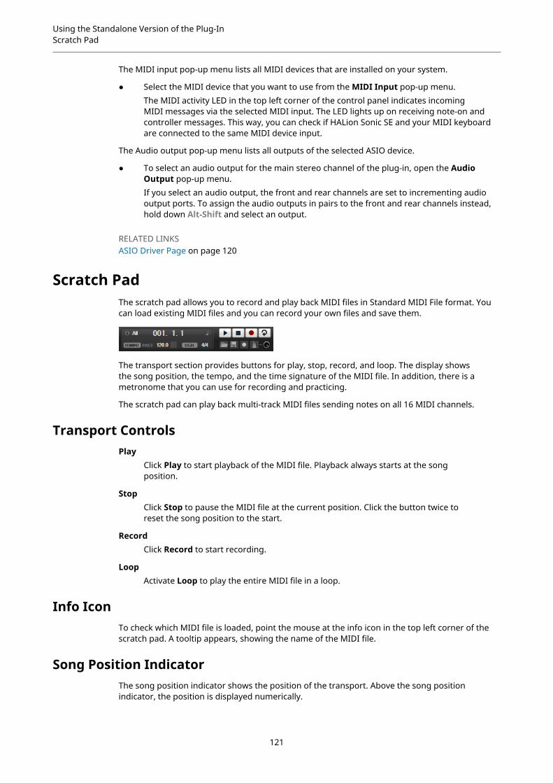
Using the Standalone Version of the Plug-InScratch Pad
The MIDI input pop-up menu lists all MIDI devices that are installed on your system.
● Select the MIDI device that you want to use from the MIDI Input pop-up menu.The MIDI activity LED in the top left corner of the control panel indicates incomingMIDI messages via the selected MIDI input. The LED lights up on receiving note-on andcontroller messages. This way, you can check if HALion Sonic SE and your MIDI keyboardare connected to the same MIDI device input.
The Audio output pop-up menu lists all outputs of the selected ASIO device.
● To select an audio output for the main stereo channel of the plug-in, open the AudioOutput pop-up menu.If you select an audio output, the front and rear channels are set to incrementing audiooutput ports. To assign the audio outputs in pairs to the front and rear channels instead,hold down Alt-Shift and select an output.
RELATED LINKSASIO Driver Page on page 120
Scratch PadThe scratch pad allows you to record and play back MIDI files in Standard MIDI File format. Youcan load existing MIDI files and you can record your own files and save them.
The transport section provides buttons for play, stop, record, and loop. The display showsthe song position, the tempo, and the time signature of the MIDI file. In addition, there is ametronome that you can use for recording and practicing.
The scratch pad can play back multi-track MIDI files sending notes on all 16 MIDI channels.
Transport ControlsPlay
Click Play to start playback of the MIDI file. Playback always starts at the songposition.
StopClick Stop to pause the MIDI file at the current position. Click the button twice toreset the song position to the start.
RecordClick Record to start recording.
LoopActivate Loop to play the entire MIDI file in a loop.
Info IconTo check which MIDI file is loaded, point the mouse at the info icon in the top left corner of thescratch pad. A tooltip appears, showing the name of the MIDI file.
Song Position IndicatorThe song position indicator shows the position of the transport. Above the song positionindicator, the position is displayed numerically.
121

Using the Standalone Version of the Plug-InScratch Pad
After loading a MIDI file, the display shows the full length of the file.
● To move the transport to a different song position, drag the song position indicator to thenew position.
● To switch the time format between Time and Bars, click Select Time Format in the topright corner of the display.
Tempo and Time SignatureBelow the song position display, the Tempo and Time Signature fields are located. These fieldsprovide HALion Sonic SE with tempo and time signature information. These settings are used bythe scratch pad and the metronome.
Fixed Tempo/Tempo TrackSet this parameter to Track to follow the original tempo of the MIDI file.Set this parameter to Fixed to enter the tempo manually. You can either enter thevalue directly in the value field or you can enter a tempo by repeatedly clicking theTap to set Tempo field next to the value field.
Tempo ValueDetermines the tempo of the MIDI file.
Adjust TempoIf the Tempo Track option is selected, this parameter is available, allowing you toscale the playback relatively to the original tempo of the MIDI file.
Time SignatureDetermines the time signature. You can enter the new signature as fractions ofbeats.
Recording Your Performance
PROCEDURE
1. Click the record symbol below the Record button to select a record mode.
● To start recording immediately when you click the record button, select Direct.
● To start recording with the first MIDI note, select MIDI.
● To start the recording after a count-in of one bar, select Count In 1.
● To start the recording after a count-in of 2 bars, select Count In 2.
2. Click the Record button to start recording.To indicate that the recording is running, the song position indicator moves from left toright.
3. When you are done recording, click the Stop button.
RELATED LINKSSaving a MIDI File on page 123
Using the Metronome
PROCEDURE
● To select the playback mode of the metronome, click Metronome and select one of theoptions from the pop-up menu:
● If On is selected, the metronome is activated and plays continuously.
122

Using the Standalone Version of the Plug-InLoading a MIDI File
● If Count In is selected, the metronome plays only during the count-in of arecording.
● To deactivate the metronome, select Off.
Loading a MIDI FileYou can load MIDI files in Standard MIDI File format (file name extension .mid).
PROCEDURE
1. Click the Load MIDI File button below the transport buttons.
2. In the file dialog, select the file that you want to use.
3. Click Open to load the MIDI file.
MIDI Channel FilterIf a multitrack MIDI file is loaded, you can play back all MIDI events or only the events of aspecific MIDI channel.
● To specify which events to play back, click the MIDI Channel Filter field to the right of theinfo icon and select an option from the pop-up menu.
Saving a MIDI FilePROCEDURE
1. Click the Save MIDI File button below the transport buttons.
2. In the file dialog, specify a location and a file name.
3. Click Save to save your recorded performance as a MIDI file.
Master Volume
Use the volume control on the right to set the master volume of the outputs of the standaloneversion of HALion Sonic SE. This includes the volume of the main outputs, the rear outputs, andthe output of the metronome.
123

Index
AAudio Output 120
DDelay Effects 76Distortion Effects 86Dynamics Effects 100
EEdit Page 29Effect Slots 68Effects 67
About 68Amplifier 86Auto Filter 79Brickwall Limiter 104Chorus 90Compressor 100Distortion 87DJ-EQ 78Envelope Shaper 108Expander 105Flanger 91Frequency Shifter 95Gate 107Graphic EQ 78Limiter 104Maximizer 105MorphFilter 82Multi Delay 76Octaver 90Phaser 93Resonator 83Reverb 74REVerence 73Ring Modulator 94Rotary 97Step Flanger 92Stereo Pan 108StereoEnhancer 109Studio EQ 77Tape Saturator 89Tremolo 93Tube Compressor 102Tube Saturator 89Using 68Vibrato 99
Vintage Compressor 101Vintage Ensemble 99VST Amp 87WahWah 85
Effects Page 68EQ Effects 77
FFilter Effects 79
HHALion 3 Effects 109
LLegacy Effects 109
MMacro Page 29Master Section 13MediaBay
About 25Filters 26Managing files 25Results List 26
MIDI ControllersAbout 64Assigning 64Factory Controller Assignment 66Parameter Range 65
MIDI Input 120MIDI Page 63Mix Page
About 67Mixing 67Modulation Effects 90Multis
About 22
OOptions Page 17
PPanner Effects 108
124
Index
Pitch Shift Effects 90Preferences Dialog 119Presets
Module Presets 10VST Presets 10
Program Slot Section 12Programs 29
About 22Editing 29Loading 22
QQuick Controls 15
RReverb Effects 73
SSpatial Effects 108Standalone Plug-In Version
About 119Saving MIDI Files 123
TTrigger Pads 15Trip
Amplifier Settings 39Filter Settings 39Oscillator Page 33
125