hamworthy melbury he - esicms.esi.info/media/documents/hamwo_melburyhe_ml.pdf · 2016. 6. 21. ·...
TRANSCRIPT

Melbury HEHigh Efficiency Steel Shell Power Flame Boilers Gas, Oil, Biofuel or Dual Fuel Burners Outputs 530kW to 10000kW
Hamworthy
2
Costeffectivesolutionforhighsystemloads
Sustainableenergysolutions
Economicalandreliableoperation
Nominimumwaterflow
Lowstandinglosses
Robustheatexchangerdesign
LowerNOxemissions
For buildings with high heating and hot water energy demands in commercial and industrial applications, the Melbury HE provides excellent performance for the reliable delivery of low temperature hot water (LTHW).
There are 19 models in the range with outputs from 530kW to 10000kW, with a choice of fully modulating or high low matched burners, delivering operating efficiencies up to 93% nett (84% gross). The high efficiency performance of the Melbury HE exceeds the minimum requirements of the Building Regulations, and provides a cost effective solution for high heating load projects.
The burner options give a choice of fuel; Natural gas or oil. Selected models are also suitable for dual fuel arrangements.
Oil burners are suitable for 28 second Kerosene and 35 second gas oil and where matched burners are available, FAME and RME blends of liquid biofuel may be specified, offering sustainable energy solutions.
The heat exchanger is a three-pass design rated to 6 bar working pressure, which incorporates an innovative feature to reduce turbulence in the combustion chamber, which in turn reduces the production of thermal nitrogen oxide (NOx).
Additionally, there is a range of low NOx matched burners to further improve the environmental credentials of the boiler.
The thermal mass within the Melbury HE boiler can accommodate fluctuating operating conditions, and with no minimum water flow requirement, eliminates the need for a shunt pump, simplifying the hydraulic system design.
Theoptiontouseliquidbiofuel
allowstheMelburyHEboilertobe
specifiedwheresustainableenergy
solutionsarearequirement.
BE
NE
FIT
S
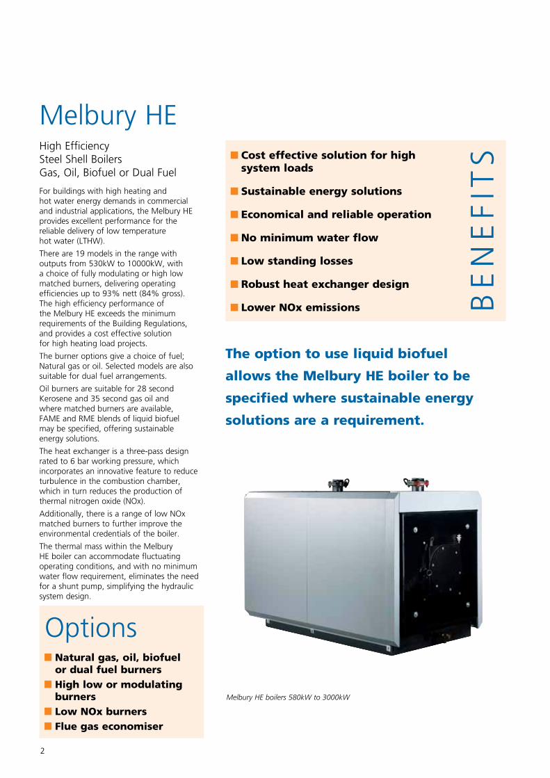
Melbury HE boilers 580kW to 3000kW
Melbury HEHigh Efficiency Steel Shell BoilersGas, Oil, Biofuel or Dual Fuel
OptionsNaturalgas,oil,biofuelordualfuelburnersHighlowormodulatingburnersLowNOxburnersFluegaseconomiser
3
SpecificationMelbury HE
The Melbury HE is a high quality steel shell boiler range, designed to deliver high outputs and high efficiency performance.
The boilers can be used individually, or in multiple boiler configurations, and are suitable for use on open vented or sealed low temperature hot water heating systems. For domestic hot water (DHW) production they can be used in conjunction with the Hamworthy Powerstock range of calorifiers.
LowNOxPerformanceMelbury HE boilers are designed with a three-pass heat exchanger to maximise heat transfer and performance of the boiler.
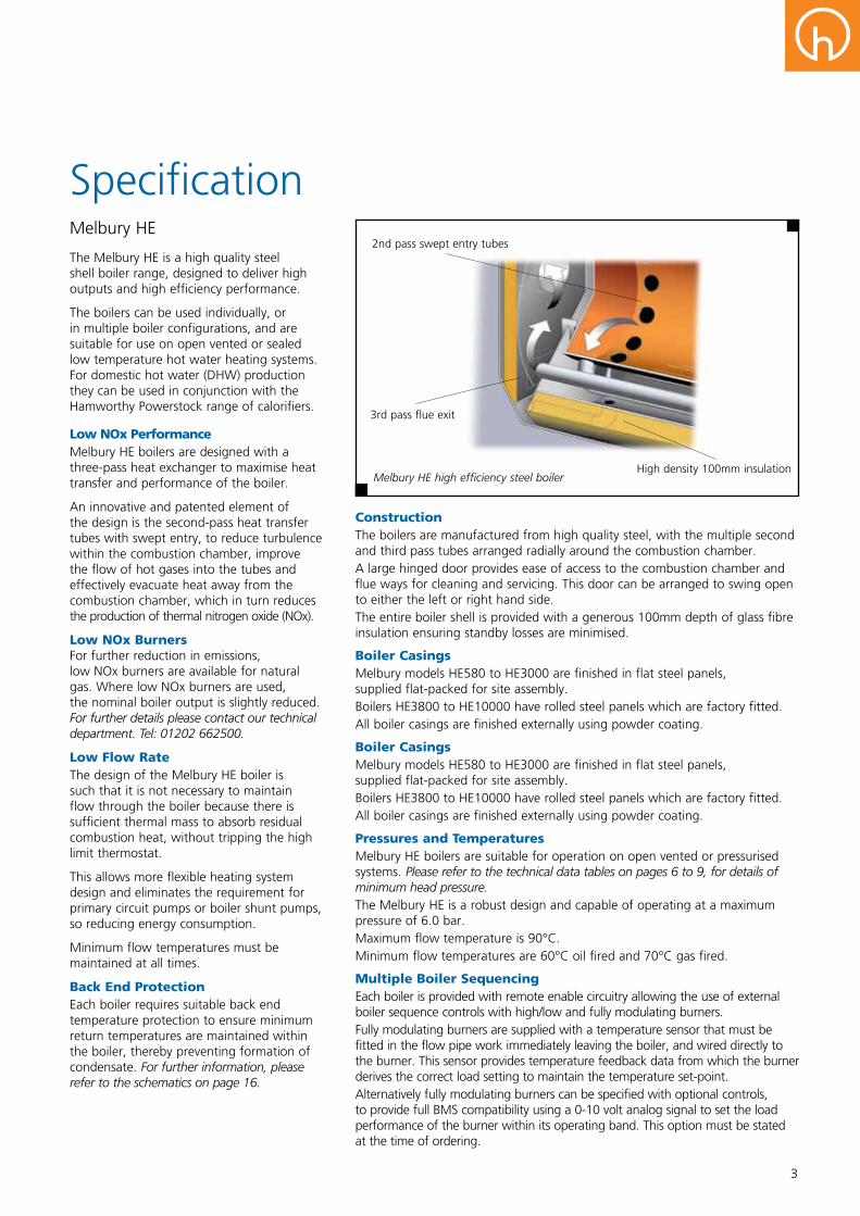
An innovative and patented element of the design is the second-pass heat transfer tubes with swept entry, to reduce turbulence within the combustion chamber, improve the flow of hot gases into the tubes and effectively evacuate heat away from the combustion chamber, which in turn reduces the production of thermal nitrogen oxide (NOx).
LowNOxBurnersFor further reduction in emissions, low NOx burners are available for natural gas. Where low NOx burners are used, the nominal boiler output is slightly reduced. For further details please contact our technical department. Tel: 01202 662500.
LowFlowRateThe design of the Melbury HE boiler is such that it is not necessary to maintain flow through the boiler because there is sufficient thermal mass to absorb residual combustion heat, without tripping the high limit thermostat.
This allows more flexible heating system design and eliminates the requirement for primary circuit pumps or boiler shunt pumps, so reducing energy consumption.
Minimum flow temperatures must be maintained at all times.
BackEndProtectionEach boiler requires suitable back end temperature protection to ensure minimum return temperatures are maintained within the boiler, thereby preventing formation of condensate. For further information, please refer to the schematics on page 16.
ConstructionThe boilers are manufactured from high quality steel, with the multiple second and third pass tubes arranged radially around the combustion chamber.A large hinged door provides ease of access to the combustion chamber and flue ways for cleaning and servicing. This door can be arranged to swing open to either the left or right hand side.The entire boiler shell is provided with a generous 100mm depth of glass fibre insulation ensuring standby losses are minimised.
BoilerCasingsMelbury models HE580 to HE3000 are finished in flat steel panels, supplied flat-packed for site assembly.Boilers HE3800 to HE10000 have rolled steel panels which are factory fitted.All boiler casings are finished externally using powder coating.
BoilerCasingsMelbury models HE580 to HE3000 are finished in flat steel panels, supplied flat-packed for site assembly.Boilers HE3800 to HE10000 have rolled steel panels which are factory fitted.All boiler casings are finished externally using powder coating.
PressuresandTemperaturesMelbury HE boilers are suitable for operation on open vented or pressurised systems. Please refer to the technical data tables on pages 6 to 9, for details of minimum head pressure.The Melbury HE is a robust design and capable of operating at a maximum pressure of 6.0 bar.Maximum flow temperature is 90°C. Minimum flow temperatures are 60°C oil fired and 70°C gas fired.
MultipleBoilerSequencingEach boiler is provided with remote enable circuitry allowing the use of external boiler sequence controls with high/low and fully modulating burners.Fully modulating burners are supplied with a temperature sensor that must be fitted in the flow pipe work immediately leaving the boiler, and wired directly to the burner. This sensor provides temperature feedback data from which the burner derives the correct load setting to maintain the temperature set-point.Alternatively fully modulating burners can be specified with optional controls, to provide full BMS compatibility using a 0-10 volt analog signal to set the load performance of the burner within its operating band. This option must be stated at the time of ordering.
Melbury HE high efficiency steel boiler
2nd pass swept entry tubes
3rd pass flue exit
High density 100mm insulation
4
SpecificationMelbury HE
ControlPanelThe boiler control panel on all models is supplied in a fabricated steel housing for mounting on the boiler on site.
For Melbury models HE530 to HE895, the control panel is positioned on top of the boiler, with an optional position on the side, left or right.
On models HE1150 to HE3000 the control panel position is on the side of the boiler only, left or right.
On boiler models HE3800 to HE10000 the control panel position is also on the side of the boiler, left or right.
For further details, refer to drawings on page 10.
ControlsThe pre-wired control panel includes the following features:
n Control fuse 6.3 AT
n Limit thermostat 110°C manual reset
n Control thermostat 35°C to 90°C
n High fire control thermostat 35°C to 90°C
n Burner on/off switch
n Limit thermostat test button
n Overheat indicator lamp
n Safety interlock indicator lamp
n Burner lock out lamp
n Water temperature thermometer
n High and low fire hours run meters
n 5 Volt free contacts for remote signalling
ExternalControlsInterfaceEach boiler control panel is supplied with controls interfaces that can be connected to external controls solutions for:
n Emergency on off circuit
n Safety interlock circuit
n Remote on off circuit (remote enable)
Emergency on off circuit immediately cuts the electrical supply to the boiler control panel stopping burner operation and heat generation.
RemoteSignallingRemote signalling is achieved via a set of volt free contacts which indicate the following: n Burner low fire operation
n Burner high fire operation
n Overheat lockout
n Burner lockout
n External interlock fault
BurnerConnectionEach control panel is supplied with a set of cables for making electrical connections to the burner. Final connection between control panel and burner is made using polarised plugs and sockets.
BurnersThe Melbury HE range of boilers is available with a choice of high/low or fully modulating matched Riello burners. Burners from other manufactures may be available on request.
There is a choice of fuel; natural gas or oil. Selected models are also suitable for dual fuel arrangements. Oil burners are suitable for 28 second Kerosene and 35 second gas oil and where matched burners are available, FAME and RME blends of liquid biofuel may be specified.
Most gas burners used with Melbury HE boilers will require gas supply pressures in excess of those guaranteed from the national grid, therefore a gas booster may be needed for normal operation. For gas pressure requirements with matched gas burners see technical data tables on pages 6 to 9.
A drilled mounting plate is supplied to suit the specified burner. Burners are supplied with a flying lead and plug for connection to the boiler control panel. For new buildings with a total heat load greater than 500kW, it is a requirement of Building Regulations Part L: 2006 that each boiler will be fitted with a fully modulating gas burner, or a multi stage burner for oil fired installations.
LiquidBiofuelLiquid biofuel must conform with the requirements of EN 14213. Suitable classifications of liquid biofuel for use with Riello burners are FAME (Fatty Acid Methyl Ester) and RME (Rape Methyl Ester) blends up to B50. Higher concentrations of liquid biofuel up to B100 can be accommodated, however, burners must be matched specifically to the fuel specification.
All liquid biofuel specifications must be referred to our technical department. Tel: 01202 662500.
Where external storage is used for liquid biofuel, it is recommended that Kerosene (Class C2) blend is used. Kerosene blends have better cold filter plugging points (CFPP) than gas oil (Class D) blends, providing improved reliability during cold weather. Other blends may cause problems with gelling and blockages in the fuel system when ambient temperatures are very low.
Blended liquid biofuel must be sourced from a reputable supplier, capable of demonstrating compliance with a certified quality assurance system such as ISO 9000, and able to provide the correct specification of fuel.
Liquid biofuel burners are supplied with specific flexible oil feed hoses. It is important to stipulate the use of liquid biofuel at the time of ordering.
For further advise on liquid biofuel, please contact our technical department. Tel: 01202 662500.
5
LiquidBiofuelStorageandHandlingOil storage tank manufacturers’ must verify that their tank construction and ancillary equipment is suitable for use with liquid biofuel.
Any suitable existing oil storage tank must be thoroughly cleaned prior to use.
Liquid biofuels are hydroscopic and any traces of water absorbed into the oil could result in blocked filters, oil pumps or nozzles.
Liquid biofuels can be susceptible to bacteria growth so it is advisable to implement management best practice for storage of the fuel. Prudent precautions such as using additives and limiting the storage volume (not oversizing) may help limit bacterial growth.
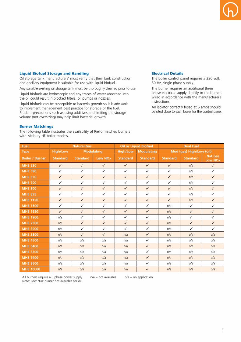
Fuel Natural Gas Oil or Liquid Biofuel Dual Fuel
Type High/Low Modulating High/Low Modulating Mod (gas) High/Low (oil)
Boiler / Burner Standard Standard Low NOx Standard Standard Standard StandardNat Gas
Low NOx
MHE 530 n/a MHE 580 n/a MHE 630 n/a MHE 700 n/a MHE 800 n/a MHE 895 n/a MHE 1150 n/a MHE 1300 n/a MHE 1650 n/a MHE 1900 n/a n/a MHE 2500 n/a n/a MHE 3000 n/a n/a MHE 3800 n/a n/a n/a o/a o/a
MHE 4500 n/a o/a o/a n/a n/a o/a o/a
MHE 5400 n/a o/a o/a n/a n/a o/a o/a
MHE 6300 n/a o/a o/a n/a n/a o/a o/a
MHE 7400 n/a o/a o/a n/a n/a o/a o/a
MHE 8600 n/a o/a o/a n/a n/a o/a o/a
MHE 10000 n/a o/a o/a n/a n/a o/a o/a
All burners require a 3 phase power supply. n/a = not available o/a = on application Note: Low NOx burner not available for oil
ElectricalDetailsThe boiler control panel requires a 230 volt, 50 Hz, single phase supply.
The burner requires an additional three phase electrical supply directly to the burner, wired in accordance with the manufacturer’s instructions.
An isolator correctly fused at 5 amps should be sited close to each boiler for the control panel.
BurnerMatchingsThe following table illustrates the availability of Riello matched burners with Melbury HE boiler models.

6
Melbury HE Boilers - 530kW to 895kWPerformance and General Data
Technical Data
BoilerModel MHE530 MHE580 MHE630 MHE700 MHE800 MHE895
Energy
Building Regulations seasonal (%) gross efficiency 84.99 85.34 85.16 85.63 85.33 85.82
Boiler output at 80/60°C kW Btu/h x 1000
530 1808
580 1979
630 2150
700 2388
800 2730
895 3054
Boiler input (gross) - Maximum kW Btu/h x 1000
645 2201
697 2379
762 2599
838 2859
966 3296
1068 3644
Boiler input (nett) - Maximum kW Btu/h x 1000
581 1983
628 2144
686 2341
755 2576
870 2970
962 3283
Boiler output at 80/60°C kW for natural gas - Minimum Btu/h x 1000
95 324
121 413
121 413
175 597
175 597
269 918
Boiler output at 80/60°C kW for oil - Minimum Btu/h x 1000
211 720
272 928
272 928
355 1211
355 1211
494 1685
Water
Water content litres 530 650 650 790 790 960
System design flow rate at 20°C ∆T rise l/s 6.34 6.94 7.54 8.37 9.57 10.71
Waterside pressure loss at 20°C ∆T rise mbar 11 13 15 18 24 30
System design flow rate at 10°C ∆T rise l/s 12.68 13.88 15.07 16.74 19.14 21.41
Waterside pressure loss at 10°C ∆T rise mbar 42 50 59 73 96 120
Water flow rate - Minimum l/s No minimum flow rate
Water pressure - Maximum barg 6
Water pressure - Minimum barg 0.55 0.55 0.65 0.50 0.70 0.75
Water flow temperature - Maximum °C 90
Water flow temperature - Minimum °C 70°C Nat Gas / 60°C Oil
Water return temperature - Minimum °C 60°C Nat Gas / 50°C Oil
Fuel
Flow rate for natural gas - Maximum m3/h 61.5 66.5 72.6 79.9 92.1 101.8
Inlet pressure for natural gas - Nominal* mbar 20
Inlet pressure for natural gas - Maximum mbar 50
Input rate for oil (35 Sec) l/h 61.0 66.0 72.0 79.3 91.4 101.0
Flue
Flue gas volume at 15°C, 9%CO2, m3/hN.T.P - Approx 737.9 799.3 891.6 983.8 1137.5 1229.8
Flue gas temperature at 80/60°C °C 209 187 197 179 196 172
Combustion chamber resistance mbar 5.97 4.22 5.06 5.03 6.74 5.33
Connections
Water flow connection PN6 DN100
Water return connection PN6 DN100
Gas inlet connection Rc2"
Drain connection R1¼"
Flue diameter (O/D) - Nominal mm 200 250 300
Flue hood drain connection R¾"
Electrical supply for boiler 230V 1Ph 50Hz
Electrical supply for burner 400V 3Ph 50Hz
Shipping weight (excluding burner) - Approx kg 1130 1490 1490 1810 1810 2000
Notes: 1. Data applies to gas and oil fired boilers, unless otherwise stated. 2. * The nominal gas inlet pressure shown is for Riello burners. Alternative burners and dual fuel burner requirements may change. Nominal gas inlet pressure must be maintained under full gas flow operating conditions. 3. The performance specification for boilers with low NOx burners may be reduced. For further details please contact our technical department. Tel: 01202 662500.
7
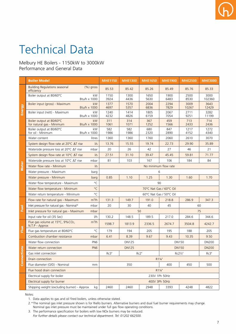
Melbury HE Boilers - 1150kW to 3000kWPerformance and General Data
Technical Data
BoilerModel MHE1150 MHE1300 MHE1650 MHE1900 MHE2500 MHE3000
Energy
Building Regulations seasonal (%) gross efficiency 85.53 85.42 85.26 85.49 85.76 85.33
Boiler output at 80/60°C kW Btu/h x 1000
1150 3924
1300 4436
1650 5630
1900 6483
2500 8530
3000 102360
Boiler input (gross) - Maximum kW Btu/h x 1000
1377 4697
1570 5357
2004 6836
2294 7829
3009 10267
3643 12429
Boiler input (nett) - Maximum kW Btu/h x 1000
1240 4232
1414 4826
1805 6159
2067 7054
2711 9251
3282 11199
Boiler output at 80/60°C kW for natural gas - Minimum Btu/h x 1000
311 1061
314 1071
367 1252
459 1566
713 2433
714 2436
Boiler output at 80/60°C kW for oil - Minimum Btu/h x 1000
582 1986
582 1986
680 2320
847 2890
1217 4152
1272 4340
Water
Water content litres 1360 1360 1760 2060 2610 3070
System design flow rate at 20°C ∆T rise l/s 13.76 15.55 19.74 22.73 29.90 35.89
Waterside pressure loss at 20°C ∆T rise mbar 20 26 42 27 46 21
System design flow rate at 10°C ∆T rise l/s 27.51 31.10 39.47 45.45 59.81 71.77
Waterside pressure loss at 10°C ∆T rise mbar 81 103 167 106 184 84
Water flow rate - Minimum l/s No minimum flow rate
Water pressure - Maximum barg 6
Water pressure - Minimum barg 0.85 1.10 1.25 1.30 1.60 1.70
Water flow temperature - Maximum °C 90
Water flow temperature - Minimum °C 70°C Nat Gas / 60°C Oil
Water return temperature - Minimum °C 60°C Nat Gas / 50°C Oil
Fuel
Flow rate for natural gas - Maximum m3/h 131.3 149.7 191.0 218.8 286.9 347.3
Inlet pressure for natural gas - Nominal* mbar 20 30 40 45 60
Inlet pressure for natural gas - Maximum mbar 50 75
Input rate for oil (35 Sec) l/h 130.2 148.5 189.5 217.0 284.6 344.6
Flue
Flue gas volume at 15°C, 9%CO2, m3/hN.T.P - Approx 1598.7 1813.9 2336.5 2674.7 3504.8 4242.7
Flue gas temperature at 80/60°C °C 179 194 205 195 188 205
Combustion chamber resistance mbar 6.41 8.39 9.67 9.43 10.35 9.50
Connections
Water flow connection PN6 DN125 DN150 DN200
Water return connection PN6 DN125 DN150 DN200
Gas inlet connection Rc3" Rc2" Rc2½" Rc3"
Drain connection R1¼"
Flue diameter (O/D) - Nominal mm 350 400 450 500
Flue hood drain connection R1¼"
Electrical supply for boiler 230V 1Ph 50Hz
Electrical supply for burner 400V 3Ph 50Hz
Shipping weight (excluding burner) - Approx kg 2460 2460 2948 3393 4248 4822
Notes: 1. Data applies to gas and oil fired boilers, unless otherwise stated. 2. * The nominal gas inlet pressure shown is for Riello burners. Alternative burners and dual fuel burner requirements may change. Nominal gas inlet pressure must be maintained under full gas flow operating conditions. 3. The performance specification for boilers with low NOx burners may be reduced. For further details please contact our technical department. Tel: 01202 662500.

8
Melbury HE Boilers - 3800kW to 6300kWPerformance and General Data
Technical Data
BoilerModel MHE3800 MHE4500 MHE5400 MHE6300
Energy
Building Regulations seasonal efficiency (%) gross 85.42 85.55 85.67 85.63
Boiler output at 80/60°C kW Btu/h x 1000
3800 12966
4500 15354
5400 18425
6300 21496
Boiler input (gross) - Maximum kW Btu/h x 1000
4594 15675
5440 18562
6507 22202
7575 25846
Boiler input (nett) - Maximum kW Btu/h x 1000
4139 14123
4902 16724
5863 20004
6825 23287
Boiler output at 80/60°C kW for natural gas - Minimum Btu/h x 1000
880 3003
1160 3958
1473 5026
1582 5398
Boiler output at 80/60°C kW for oil - Minimum Btu/h x 1000
2012 6865
2518 8591
2930 9997
3442 11744
Water
Water content litres 3805 5385 6060 9300
System design flow rate at 20°C ∆T rise l/s 45.45 53.83 64.59 75.36
Waterside pressure loss at 20°C ∆T rise mbar 44 62 89 47
System design flow rate at 10°C ∆T rise l/s 90.91 107.66 129.19 150.72
Waterside pressure loss at 10°C ∆T rise mbar 176 248 356 188
Water flow rate - Minimum l/s No minimum flow rate
Water pressure - Maximum barg 6
Water pressure - Minimum barg 1.8 2.2
Water flow temperature - Maximum °C 90
Water flow temperature - Minimum °C 70°C Nat Gas / 60°C Oil
Water return temperature - Minimum °C 60°C Nat Gas / 50°C Oil
Fuel
Flow rate for natural gas - Maximum m3/h 438.0 518.7 620.4 722.2
Inlet pressure for natural gas - Nominal* mbar 60 Data on application
Inlet pressure for natural gas - Maximum mbar 75 100 Data on application
Input rate for oil (35 Sec) l/h 434.6 514.6 615.5 716.5
Flue
Flue gas volume at 15°C, 9%CO2, m3/hN.T.P - Approx 5503.2 6517.7 7809.0 9069.5
Flue gas temperature at 80/60°C °C 198 196 190 185
Combustion chamber resistance mbar 11.01 10.18 10.91 12.46
Connections
Water flow connection PN6 DN200 DN250
Water return connection PN6 DN200 DN250
Gas inlet connection Rc3" Rc4" Data on application
Safety valve connection PN16 DN80 DN100
Drain connection PN6 R2” DN65
Flue diameter (O/D) - Nominal mm 550 600 650 700
Flue hood drain connection R1¼" R2"
Electrical supply for boiler 230V 1Ph 50Hz
Electrical supply for burner 400V 3Ph 50Hz
Shipping weight (excluding burner) - Approx kg 7025 8425 10075 13545
Notes: 1. Data applies to gas and oil fired boilers, unless otherwise stated. 2. * The nominal gas inlet pressure shown is for Riello burners. Alternative burners and dual fuel burner requirements may change. Nominal gas inlet pressure must be maintained under full gas flow operating conditions. 3. The performance specification for boilers with low NOx burners may be reduced. For further details please contact our technical department. Tel: 01202 662500.
9
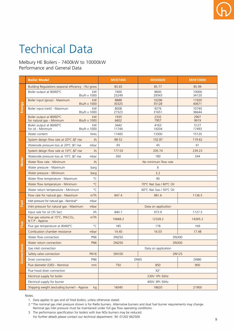
Melbury HE Boilers - 7400kW to 10000kWPerformance and General Data
Technical Data
BoilerModel MHE7400 MHE8600 MHE10000
Energy
Building Regulations seasonal efficiency (%) gross 85.65 85.77 85.99
Boiler output at 80/60°C kW Btu/h x 1000
7400 25249
8600 29343
10000 34120
Boiler input (gross) - Maximum kW Btu/h x 1000
8888 30325
10296 35128
11920 40671
Boiler input (nett) - Maximum kW Btu/h x 1000
8008 27323
9276 31651
10740 36644
Boiler output at 80/60°C kW for natural gas - Minimum Btu/h x 1000
1935 6602
2332 7957
2907 9919
Boiler output at 80/60°C kW for oil - Minimum Btu/h x 1000
3442 11744
4163 14204
5127 17493
Water
Water content litres 11400 13300 15120
System design flow rate at 20°C ∆T rise l/s 88.52 102.87 119.62
Waterside pressure loss at 20°C ∆T rise mbar 65 45 61
System design flow rate at 10°C ∆T rise l/s 177.03 205.74 239.23
Waterside pressure loss at 10°C ∆T rise mbar 260 180 244
Water flow rate - Minimum l/s No minimum flow rate
Water pressure - Maximum barg 6
Water pressure - Minimum barg 2.2
Water flow temperature - Maximum °C 90
Water flow temperature - Minimum °C 70°C Nat Gas / 60°C Oil
Water return temperature - Minimum °C 60°C Nat Gas / 50°C Oil
Fuel
Flow rate for natural gas - Maximum m3/h 847.4 981.6 1136.5
Inlet pressure for natural gas - Nominal* mbar
Inlet pressure for natural gas - Maximum mbar Data on application
Input rate for oil (35 Sec) l/h 840.7 973.9 1127.5
Flue
Flue gas volume at 15°C, 9%CO2, m3/hN.T.P - Approx 10668.2 12328.2 14265.2
Flue gas temperature at 80/60°C °C 185 178 169
Combustion chamber resistance mbar 14.40 16.03 17.48
Connections
Water flow connection PN6 DN250 DN300
Water return connection PN6 DN250 DN300
Gas inlet connection Data on application
Safety valve connection PN16 DN100 DN125
Drain connection PN6 DN65 DN80
Flue diameter (O/D) - Nominal mm 750 850 900
Flue hood drain connection R2"
Electrical supply for boiler 230V 1Ph 50Hz
Electrical supply for burner 400V 3Ph 50Hz
Shipping weight (excluding burner) - Approx kg 16040 18620 21900
Notes: 1. Data applies to gas and oil fired boilers, unless otherwise stated. 2. * The nominal gas inlet pressure shown is for Riello burners. Alternative burners and dual fuel burner requirements may change. Nominal gas inlet pressure must be maintained under full gas flow operating conditions. 3. The performance specification for boilers with low NOx burners may be reduced. For further details please contact our technical department. Tel: 01202 662500.
10
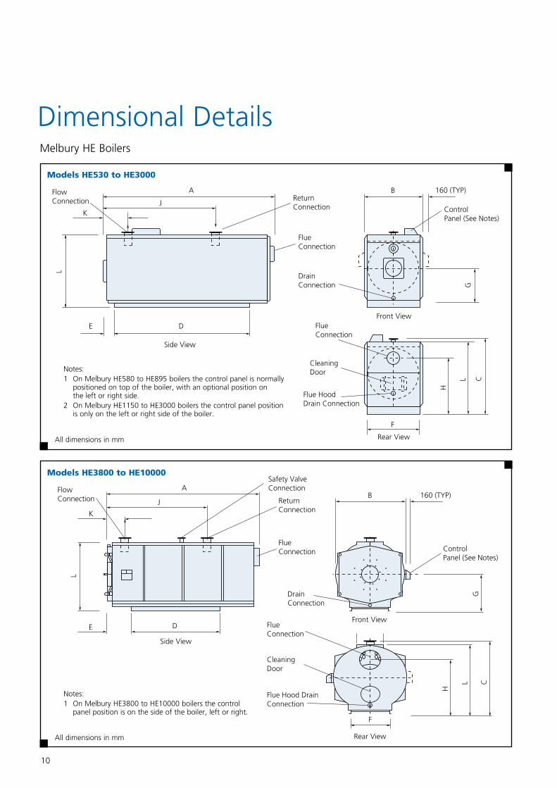
Melbury HE Boilers
Dimensional Details
All dimensions in mm
All dimensions in mm
ModelsHE530toHE3000
ModelsHE3800toHE10000
Notes:1 On Melbury HE580 to HE895 boilers the control panel is normally positioned on top of the boiler, with an optional position on the left or right side.2 On Melbury HE1150 to HE3000 boilers the control panel position is only on the left or right side of the boiler.
Notes:1 On Melbury HE3800 to HE10000 boilers the control panel position is on the side of the boiler, left or right.
Side View
Front View
Rear View
Side View
Front View
Rear View
11
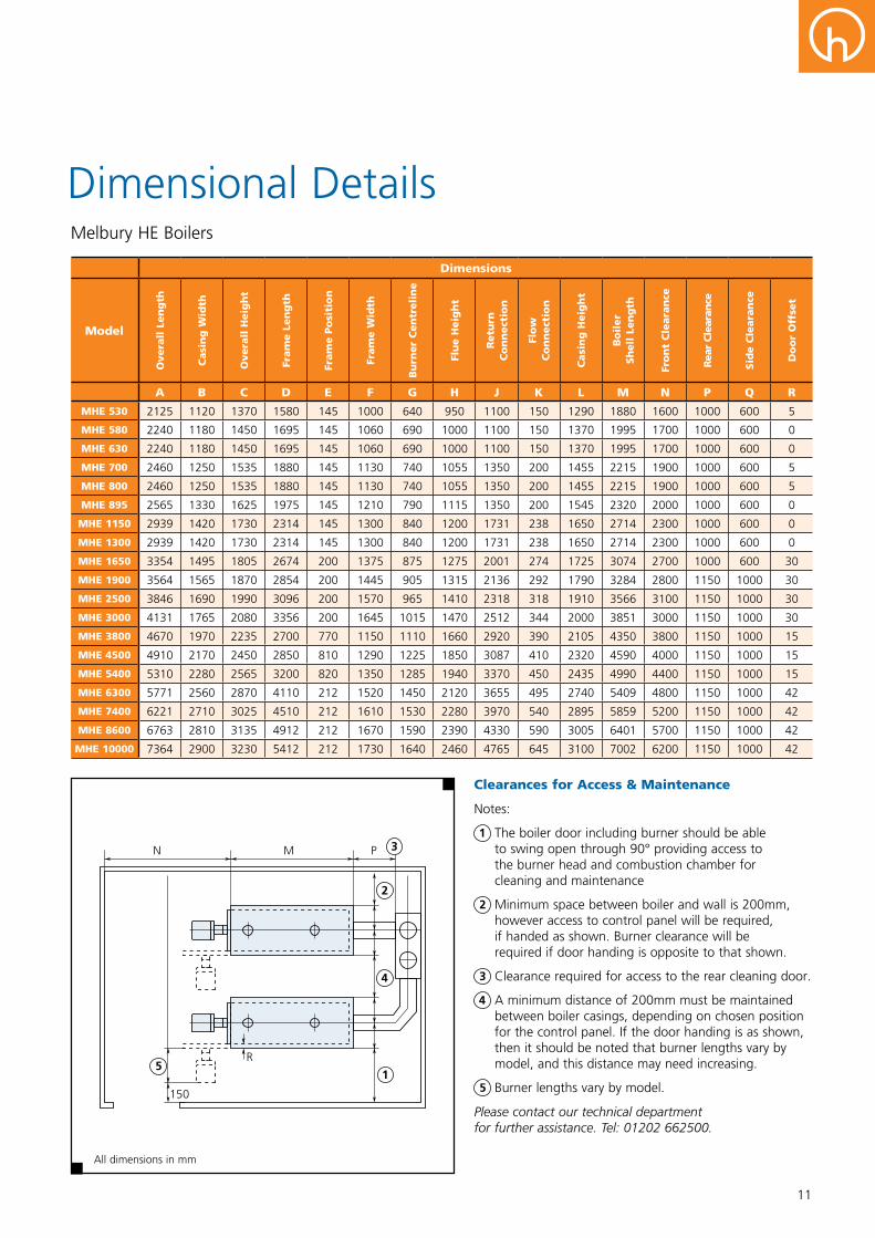
Dimensions
Model
OverallLength
CasingWidth
OverallHeight
FrameLength
FramePosition
FrameWidth
BurnerCentreline
FlueHeight
Return
Connection
Flow
Connection
CasingHeight
Boiler
ShellLength
FrontClearance
RearClearance
SideClearance
DoorOffset
A B C D E F G H J K L M N P Q R
MHE530 2125 1120 1370 1580 145 1000 640 950 1100 150 1290 1880 1600 1000 600 5
MHE580 2240 1180 1450 1695 145 1060 690 1000 1100 150 1370 1995 1700 1000 600 0
MHE630 2240 1180 1450 1695 145 1060 690 1000 1100 150 1370 1995 1700 1000 600 0
MHE700 2460 1250 1535 1880 145 1130 740 1055 1350 200 1455 2215 1900 1000 600 5
MHE800 2460 1250 1535 1880 145 1130 740 1055 1350 200 1455 2215 1900 1000 600 5
MHE895 2565 1330 1625 1975 145 1210 790 1115 1350 200 1545 2320 2000 1000 600 0
MHE1150 2939 1420 1730 2314 145 1300 840 1200 1731 238 1650 2714 2300 1000 600 0
MHE1300 2939 1420 1730 2314 145 1300 840 1200 1731 238 1650 2714 2300 1000 600 0
MHE1650 3354 1495 1805 2674 200 1375 875 1275 2001 274 1725 3074 2700 1000 600 30
MHE1900 3564 1565 1870 2854 200 1445 905 1315 2136 292 1790 3284 2800 1150 1000 30
MHE2500 3846 1690 1990 3096 200 1570 965 1410 2318 318 1910 3566 3100 1150 1000 30
MHE3000 4131 1765 2080 3356 200 1645 1015 1470 2512 344 2000 3851 3000 1150 1000 30
MHE3800 4670 1970 2235 2700 770 1150 1110 1660 2920 390 2105 4350 3800 1150 1000 15
MHE4500 4910 2170 2450 2850 810 1290 1225 1850 3087 410 2320 4590 4000 1150 1000 15
MHE5400 5310 2280 2565 3200 820 1350 1285 1940 3370 450 2435 4990 4400 1150 1000 15
MHE6300 5771 2560 2870 4110 212 1520 1450 2120 3655 495 2740 5409 4800 1150 1000 42
MHE7400 6221 2710 3025 4510 212 1610 1530 2280 3970 540 2895 5859 5200 1150 1000 42
MHE8600 6763 2810 3135 4912 212 1670 1590 2390 4330 590 3005 6401 5700 1150 1000 42
MHE10000 7364 2900 3230 5412 212 1730 1640 2460 4765 645 3100 7002 6200 1150 1000 42
Melbury HE Boilers
Dimensional Details
ClearancesforAccess&Maintenance
Notes:
1 The boiler door including burner should be able to swing open through 90° providing access to the burner head and combustion chamber for cleaning and maintenance
2 Minimum space between boiler and wall is 200mm, however access to control panel will be required, if handed as shown. Burner clearance will be required if door handing is opposite to that shown.
3 Clearance required for access to the rear cleaning door.
4 A minimum distance of 200mm must be maintained between boiler casings, depending on chosen position for the control panel. If the door handing is as shown, then it should be noted that burner lengths vary by model, and this distance may need increasing.
5 Burner lengths vary by model.
Please contact our technical department for further assistance. Tel: 01202 662500.
All dimensions in mm
4
2
3
15

12
Application & System DataMelbury HE Boilers
The installation of the boiler MUST be in accordance with the relevant requirements of the Gas Safety Regulations, Building Regulations, IEE Regulations and the Water Supply (Water Fittings) Regulations. It should also be in accordance with any relevant requirements of the local gas region and local authority and the relevant recommendations of the following documents:
These British Standard Codes of Practice and additional publications have relevant recommendations regarding the installation of Melbury HE boilers.
BritishStandardsBS5410Code of practice for oil firing. Part 2: Installations of 45kW and above output capacity for space heating, hot water and steam supply services.
BS6798Boilers of rated input not exceeding 60kW.
BS6644Installation of Gas Fired Hot Water Boilers, 70kW to 1.8MW (nett input).
BS6700Design, installation, testing and maintenance of services supplying water for domestic use.
BS6891Installation of low pressure gas pipe work of up to 35mm (R1¼") in domestic premises.
BS6880Part 1, 2 & 3 Code of practice for low temperature hot water heating systems of output greater than 45kW.
BS7074Application, selection and installation of expansion vessels and ancillary equipment for sealed water systems. Part 2 Code of practice for low and medium temperature hot water systems.
BS7671Requirements for electrical installations. IEE Wiring Regulations. Seventeenth edition.
BSEN806-2Specification for installations inside buildings conveying water for human consumption. Design.
BSEN12828Heating systems in buildings, Design for water-based heating systems.
BS855Specification for welded steel boilers for central heating and domestic hot water supply, rated output 44kW to 3MW.
I.GasE.PublicationsIGE/UP/1 Soundness testing and purging of industrial and commercial gas installations.
IGE/UP/1A Soundness testing and direct purging of small low pressure industrial and commercial natural gas installations.
IGE/UP/2 Gas installation pipe work, boosters and compressors in industrial and commercial premises.
IGE/UP/10 Installation of gas appliances in industrial and commercial premises, Part 1 flued appliances.
HealthandSafetyExecutiveGuidance note PM5 - Automatically controlled steam and hot water boilers.
CIBSEPublicationsCIBSEGuideB Heating, ventilating, air conditioning and refrigeration.
CIBSEGuideH Building Control Systems
CIBSEGuideEnergyEfficiencyinBuildings
CIBSECommissioningCodeB:2002
DeptEnvironment,ScottishDevelopmentDept&WelshOfficeThird edition of the 1956 Clean Air Act Memorandum
Communities&LocalGovernment,England&WalesThe Building Regulations 2000: Conservation of Fuel and Power. Part L 2A, new buildings other than dwellings Part L 2B, existing buildings other than dwellings
LocationMelbury HE boilers must be installed on a non combustible flat and level surface capable of supporting the weight of the boiler when filled with water, plus any ancillary equipment. It is recommended that a plinth at least 50mm high is used for the boiler.
Adequate space should be allowed around the boiler for installation and servicing. Refer to page 11 for further details.
WaterSystemsMelbury HE boilers are suitable for operation on open vented or pressurised systems. Please refer to the technical tables on pages 6 to 9 for details of minimum water pressure. Sealed systems must comply with Health and Safety Document PM5 requirements for fuel supply cut off in the event of low and high pressure conditions. To ensure compliance, consider using a proprietary pressurisation unit with correctly sized expansion vessels.
For details of Hamworthy Chesil pressurisation units, refer to publication 500002486.
SafetyValvesEach boiler must be provided with a suitably sized and rated safety valve located in the boiler flow between the boiler flow connection and any isolating valve. The safety valve will ideally be located as close to the boiler as possible. Melbury models HE3800 to HE10000 have a safety valve connection directly onto the boiler.Safety valves should be sized in accordance with the requirements of BS 6644, and with the requirements of BS 855 for installations up to 3MW.
13
AdequateWaterFlowMelbury HE boilers do not have minimum flow rate requirements, however, care must be taken to ensure system hydraulics are designed to maintain the minimum required flow temperature of 70°C when gas firing and 60°C when oil firing, irrespective of the system return temperature. Typical hydraulic schematics are shown on page 16.
SystemFeedWaterQualityIf the boiler feed water has a high degree of hardness, >100mg CaCo3/litre, it is recommended that the water be treated to prevent the precipitation of scale and sludge in the boiler waterways. Details of additives can be obtained from any reliable manufacturer of water treatment products or the local water authority.
It should be noted however, that even if the boiler water is of average hardness, not requiring treatment, subsequent draining of the system for repair or constant make-up water due to an undetected leak will cause additional deposits and gradual build up of scale. It is essential therefore, that leaks are attended to promptly and draining is kept to absolute minimum.It is recommended that the system be flushed out at least twice before any water treatment is added.
AirandDirtRemovalTo provide effective degassing of circulating system water and for sludge removal, an air and dirt separator equipped with a fast action flushing valve must be installed in the return pipe work to the boiler.
Additionally for the removal of larger particulate matter from circulating system water, a coarse strainer must be fitted in the return pipe work to the boiler, upstream of the air and dirt separator.
OilSupplyStorageThe oil supply and storage system should be designed and installed in accordance with BS 5410 Part 1 or 2, as appropriate.
LiquidBiofuelStorageandHandlingOil storage tank manufacturers’ must verify that their tank construction and ancillary equipment is suitable for use with liquid biofuel.
Any suitable existing oil storage tank must be thoroughly cleaned prior to use.
Liquid biofuels are hydroscopic and any traces of water absorbed into the oil could result in blocked filters, oil pumps or nozzles.
Liquid biofuels can be susceptible to bacteria growth so it is advisable to implement management best practice for storage of the fuel. Prudent precautions such as using additives and limiting the storage volume (not oversizing) may help limit bacterial growth.
GasSupplySome of the larger burners may require a boosted gas supply. Hamworthy offer optional gas boosters as part of the burner boiler package.
On some models, as an alternative to using gas boosters, a larger gas train may be available. Consult with our technical sales team for further advice.
The Gas Safety (Installation and Use) Regulations require that only competent persons (Gas Safe Certified engineers), should install gas appliances.
Delivery&HandlingBoilers are delivered to site on a flatbed lorry for offloading using a crane or other suitable lifting apparatus. Each boiler is fitted with lifting eyes.
For Melbury models HE580 to HE3000 the boiler casings are finished in flat steel panels, supplied flat-packed for site assembly.
Models HE3800 to HE10000 the casings are rolled steel panels which are factory fitted.
On all models the control panel is supplied loose for fitting on site.
CommissioningHamworthy Heating strongly recommend that all boilers are commissioned by their service department or by an approved burner specialist. For more information on commissioning contact Hamworthy Heating Service Department. Tel: 0845 450 2866.
WarrantyProducts from Hamworthy Heating carry a standard two-year warranty on parts, which is extended to include labour when the product is commissioned by Hamworthy service engineers. Hamworthy can tailor packages to suit individual customer requirements, many of which include extended warranty benefits. For more information on commissioning and other after-sales services, please contact Hamworthy Heating Service Department. Tel: 0845 450 2866.
14
System HeadGuidanceNotePM5HealthandSafetyExecutive
This note states that "hot water boilers should have an automatic control apparatus to cut off fuel to the burners of gas fired plant when the water at or near the boiler flow outlet rises to a pre-determined temperature. This should provide a margin of at least 17°C below the temperature of saturated steam corresponding to the pressure at the highest point of the circulation system above the boiler. " To comply with this recommendation, the minimum system pressure is dependant on system design flow temperatures and in the case of modular installations, the temperature rise across each module. In all cases the system pressure shall not be lower than the boiler minimum operating pressure detailed in the technical data table. See pages 6 to 9.
SingleInstallations
The minimum pressure must be equal to the gauge pressure equivalent to the saturated steam temperature obtained by adding 17°C to the required boiler flow temperature. The highest point of the circulation system above the boiler should never be less than 5.1m (17ft). Required flow temperature 90°C Safety margin 17°C Equivalent saturated steam temperature 107°CFromsteamtablescorrespondinggaugepressure0.3bar–3.0mheadofwater.Minimumboileroperatingpressuretakespriorityifgreaterthancalculatedgaugepressure.See technical data tables on pages 6 to 9.
ModularInstallations
The minimum pressure should be equal to the gauge pressure equivalent to the saturated steam temperature. This is obtained by adding 17°C to the sum of the required mixed flow temperature plus the temperature rise across the modules.
System ∆t 11°C 20°C Required mixed flow Temperature 82°C 80°C Temperature rise across modules at minimum flow rate 11°C 20°C Safety margin 17°C 17°C Equivalent saturated steam temperature 110°C 117°C
Fromsteamtablescorrespondinggaugepressureat11°C∆t0.43bar,4.4m
Fromsteamtablescorrespondinggaugepressureat20°C∆t0.80bar,8.2m
Minimumboileroperatingpressuretakespriorityifgreaterthancalculatedgaugepressure.See technical data tables on pages 6 to 9.
AirSupplyandVentilation
An adequate supply of fresh air for combustion and ventilation must be provided in accordance with BS 6644. Theairsupplyshouldbefreefromcontaminationsuchasbuildingdustandinsulationfibresfromlagging.Toavoidunnecessarycleaningandservicingoftheburner,werecommendthattheboilersarenotfiredwhilstbuildingworkisbeingundertaken.
The air supply should be achieved using: n Natural ventilation supplying air with a low level opening and discharge through a smaller sized high level opening.n A fan to supply air to low level with natural discharge through a high level opening.n A fan to supply air to low level and discharged by means of a fan at a high level.Note:Fansmustbeselectedsuchthatanegativepressureisnotcreatedintheboilerhouserelativetooutsideairpressure.The air supplied for boiler house ventilation should be such that the maximum temperatures within the boiler house are as follows:n At floor level 25°C (or 100mm above the floor level)n At mid level 32°C (1.5m above floor level)n At ceiling level 40°C (or 100mm below ceiling level)Where natural ventilation is used suitable permanent openings at low level and high level connected directly to the outside air should be provided. These openings must be fitted with grilles that cannot be blocked or flooded. The free area of the grilles should be as follows:
LowLevel (Inlet) 4cm2 per kW of net heat input.HighLevel (Outlet) 2cm2 per kW of net heat input.
Ventilation
Where a boiler installation is to operate throughout the summer months, e.g. for domestic hot water production for more than 50% of the time, then additional ventilation allowances are required. Refer to BS6644 for more detailed information.
TheBuildingRegulations2000
Conservationoffuelandpower2006editionApproved Document AD L2A New Buildings, other than dwellings Approved Document AD L2B Existing Buildings, other than dwellings These new regulations came into force 6 April 2006. Compliance with the latest regulations now requires a whole buildingapproach to reduction in carbon emissions. The 2006 edition requires the use of heat generating plant as detailed in the supporting 2nd tier guide - Non Domestic Heating, Cooling and Ventilation Compliance Guide.
SeasonalEfficiency
The efficiency data used for evaluating commercial boilers is known as the heat generator seasonal efficiency and this guide states that for new buildings and existing buildings, the minimum heat generating system seasonal efficiency is 84% gross for natural gas.The heat generator seasonal efficiency for Melbury HE boilers exceed the minimum requirement. Individual boiler figures can be found in the technical data tables on pages 6 to 9.

15
Melbury HE Boilers
Electrical Wiring & Controls
ElectricalSupplyThe boiler control panel requires a 230 volts, 50 Hz, single phase electrical supply, via a fused isolator close to the boiler.
The burner requires an additional 400 volts, 50 Hz, three phase electrical supply directly to the burner, wired in accordance with the manufacturer’s instructions, and via a fused isolator close to the burner.
ExternalControlsInterface–terminals1to7Each boiler control panel is supplied with controls interfaces that can be connected to external controls solutions for:
n Emergency on/off circuit
n Safety interlock circuit
n Remote on/off circuit (remote enable)
Emergency on off circuit immediately cuts the electrical supply to the boiler control panel stopping burner operation and heat generation.
Where external controls are used, the hard wired links must be removed. All external wiring carries 230 volts and requires volt free external switches. External switches are not provided with the boiler.
BurnerWiringConnections between the boiler control panel and the burner are made using flying leads with plugs and sockets supplied with the boiler and burner.
High Low burners use both the 7 pin and 4 pin burner connections.
Fully Modulating burners only use the 7 pin burner connection.
0-10 volt control of fully modulating burners requires additional wiring dependent on burner selection.
For further details please contact our technical department. Tel: 01202 662500.
RemoteSignallingRemote signalling is achieved via a set of volt free contacts which indicate the following:
n Burner low fire operation
n Burner high fire operation
n Overheat lockout
n Burner lockout
n External interlock fault
VoltFreeContacts–terminals80to94External wiring for volt free contacts is typically connected to the common and normally open contacts. Alternatively wiring may be connected to the common and normally closed contacts.
For the external interlock fault volt free contact to operate, an external interlockfault condition power supply is required to terminal 5, 230 volts.
ExternalWiringWiring external to the boiler must be installed in accordance with I.E.E regulations. Wiring to the boiler control panel must be completed in heat resistant 3 core cable, (size 1.0mm2 c.s.a.). An isolator correctly fused at 5 amps should be sited close to each boiler for the control panel.
WiringDiagram

16
Scheme1Typical boiler installation with a full capacity single heating circuit having variable temperature control using a mixing valve.
The purpose of this circuit is to provide heat to a variable temperature heating circuit allowing for low circulation temperatures within the heating circuit, whilst providing adequate back-end temperature protection to the boilers.
Scheme2Typical boiler installation with multiple heating circuits having a mix of constant flow and variable flow with constant and variable temperature.
The purpose of this circuit is to provide heat to a mix of variable temperature and constant temperature heating circuits with differing flow and temperature requirements, whilst providing adequate back-end temperature protection to the boilers.
Due to the thermal mass of the boiler, the flow rate returning from the heating circuits can be low.
Back-endProtectionFor back-end boiler protection, a 3 port mixing valve system is recommended to blend the return water until the main system return water temperature is above dew point.
Control of the mixing valve and pump is not included with the boiler controls and must be provided by others.
Mixing valve control should be facilitated via a temperature sensor installed in the return pipe between the boiler and the mixing valve, to measure return water temperature entering the boiler. Minimum return water temperatures are 60°C for gas and 50°C for oil.
DryCyclingTo reduce dry cycling, the back-end protection mixing valve should be controlled additionally to prevent flow through the boilers when they are not firing. The valve control should be coordinated with the boiler enable signal, to switch to the pump bypass position during idle periods, preventing flow through the boiler.
Melbury HE Boilers
System Design
Scheme1VariableTemperatureHeatingCircuit
Scheme2ConstantandVariableTemperatureHeatingCircuitswithDomesticHotWater
Satisfying the heat load through a reduced number of boilers allows the burner to fire for longer periods, and reduces the number of burner starts.
With high water content boilers, energy will be saved by reducing the number of heat up cycles, and systems will be more responsive.
The motorised valve must be interlocked with the boiler enabling circuit, to ensure the valve is opened whenever a boiler is fired.
Key: A.A.V = Automatic Air Vent S.R.V = Safety Relief Valve
Key: A.A.V = Automatic Air Vent S.R.V = Safety Relief Valve
17
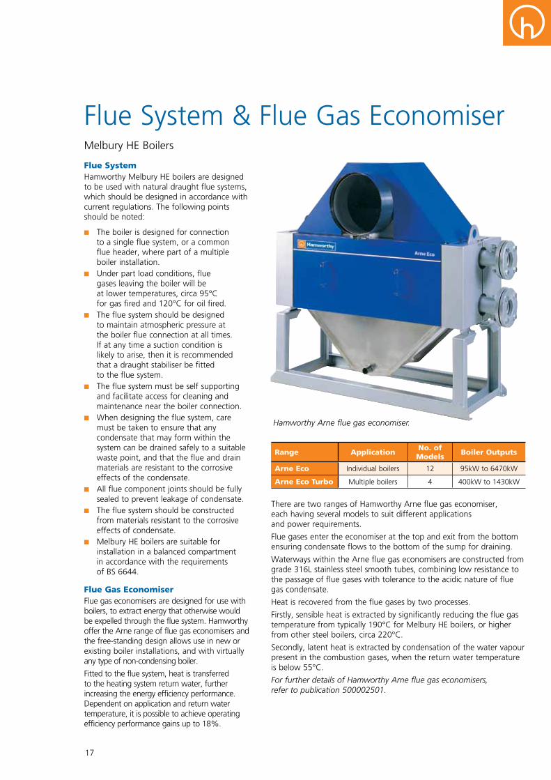
There are two ranges of Hamworthy Arne flue gas economiser, each having several models to suit different applications and power requirements.
Flue gases enter the economiser at the top and exit from the bottom ensuring condensate flows to the bottom of the sump for draining.
Waterways within the Arne flue gas economisers are constructed from grade 316L stainless steel smooth tubes, combining low resistance to the passage of flue gases with tolerance to the acidic nature of flue gas condensate.
Heat is recovered from the flue gases by two processes.
Firstly, sensible heat is extracted by significantly reducing the flue gas temperature from typically 190°C for Melbury HE boilers, or higher from other steel boilers, circa 220°C.
Secondly, latent heat is extracted by condensation of the water vapour present in the combustion gases, when the return water temperature is below 55°C.
For further details of Hamworthy Arne flue gas economisers, refer to publication 500002501.
FlueSystemHamworthy Melbury HE boilers are designed to be used with natural draught flue systems, which should be designed in accordance with current regulations. The following points should be noted:
n The boiler is designed for connection to a single flue system, or a common flue header, where part of a multiple boiler installation.n Under part load conditions, flue gases leaving the boiler will be at lower temperatures, circa 95°C for gas fired and 120°C for oil fired.n The flue system should be designed to maintain atmospheric pressure at the boiler flue connection at all times. If at any time a suction condition is likely to arise, then it is recommended that a draught stabiliser be fitted to the flue system.n The flue system must be self supporting and facilitate access for cleaning and maintenance near the boiler connection.n When designing the flue system, care must be taken to ensure that any condensate that may form within the system can be drained safely to a suitable waste point, and that the flue and drain materials are resistant to the corrosive effects of the condensate.n All flue component joints should be fully sealed to prevent leakage of condensate.n The flue system should be constructed from materials resistant to the corrosive effects of condensate.n Melbury HE boilers are suitable for installation in a balanced compartment in accordance with the requirements of BS 6644.
FlueGasEconomiserFlue gas economisers are designed for use with boilers, to extract energy that otherwise would be expelled through the flue system. Hamworthy offer the Arne range of flue gas economisers and the free-standing design allows use in new or existing boiler installations, and with virtually any type of non-condensing boiler.
Fitted to the flue system, heat is transferred to the heating system return water, further increasing the energy efficiency performance. Dependent on application and return water temperature, it is possible to achieve operating efficiency performance gains up to 18%.
Melbury HE Boilers
Flue System & Flue Gas Economiser
Range Application No.ofModels BoilerOutputs
ArneEco Individual boilers 12 95kW to 6470kW
ArneEcoTurbo Multiple boilers 4 400kW to 1430kW
Hamworthy Arne flue gas economiser.

CustomerServiceCentre
Hamworthy Heating Limited Fleets Corner, Poole, Dorset BH17 0HH
Telephone: 08454502865Email: [email protected]: www.hamworthy-heating.comHamworthy reserves the right to make changes and improvements which may necessitate alteration to the specification without prior notice.
500002500 A
Range Application No.ofModels BoilerOutputs
ArneEco Individual boilers 12 95kW to 6470kW
ArneEcoTurbo Multiple boilers 4 400kW to 1430kW
Hamworthy Heating Accreditations
ISO 9001 Quality Management System
ISO 14001 Environmental Management System
ISO 18001 Health & Safety Management System
The printed version of this brochure is produced using environmentally friendly print solutions
in partnership with our suppliers