hand-laying turn-outs - turkey creek division, nmra laying turnouts2.pdf · hand-laying turn-outs....
TRANSCRIPT
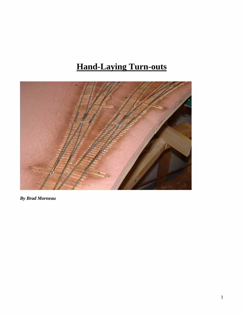
Hand-Laying Turn-outs
By Brad Morneau
1

2
Index
Section: Page(s) Introduction 3 Turnout basics 3 Fast-Track Templates 4 First Step: Plot the turnout 5 Drilling pilot holes 5 Lining up the Switch Machine Mounts 6 Making a tie template 7 Using the Tie Template 8 Laying the Ties 9 Turnout Center Template 10 Spiking in the Rails 11 Making the Frog 13 The Point-Closure-Wing rails 15 Creating the Throw-Bar 17 Creating and Installing the Brass Soldering Strips 21 Installing the Throw-bar 24 Reinforcing the Tortoise Spring Wire 25

Introduction: Welcome to my clinic on hand-laying turnouts. Why hand-lay turnouts, especially when there are many good commercial turnouts available? Well to be truthful, there isn’t any reason beyond the sense of accomplishment that goes with scratch-building anything in this great hobby of ours. It wasn’t because I didn’t like commercial switches but just to see if I could do it! In the process I was able to create switches that work very well, have no voltage drops, and are DCC friendly. Yes, there is a difference with switches and how they’re powered that makes them work better for DCC, I didn’t believe it at first either, but I’m convinced of it now. Besides, for me it was either seek psychiatric help or buy more trains, you probably already know which I chose! As of this writing I have hand-laid 21 turnouts and all are controlled by Tortoise switch machines. I include instructions for mounting these which can be disregarded if you plan for a different type of switch machine. I like them because of the internal DPDT switches that allow for power routing for the frog. Other machines have this feature as well. Let’s first proceed with a dissertation on the components of a turnout or switch as it is referred to by the actual railroads. Turnout basics The turnout consists of the following parts. The straight and curved stock rails, the straight and curved frog rails, the frog, the closure rails, wing-rails, the throw bar and finally the points.
3

Fast-Tracks Templates This approach to building turnouts in place is predicated on the use of Fast-Tracks turnout templates. They have templates for several scales and gauges. You can obtain these at the website: http://www.handlaidtrack.com/index.php also listed on this web-site is custom jigs to build the turnouts at your work-bench. For layouts with deep scenery, these jigs would be invaluable. My layout has rather shallow depth, mostly 18 inches or less so this method has worked successfully for me. Example of a Fast-Tracks template:
4

First Step: Plot the turnout The first step is to plot where the turnout is going to be placed. I use the center-line method with a cut out of a Fast-Track template to guide me. I line up the template using the center-line printed on it and mark the throw-bar and diverging route points accordingly.
After I remove the template, I make marks on the center-line for the diverging route and also complete the line for the throw-bar. This last step will tell me where to drill the switch-machine hole.
Next, drill two pilot holes, one at the throw-bar hole and the other somewhere along the switch’s main route.
After drilling the two holes, use a ruler under the layout to connect the two lines. I use this as a guide for lining up the switch-machine template.
5
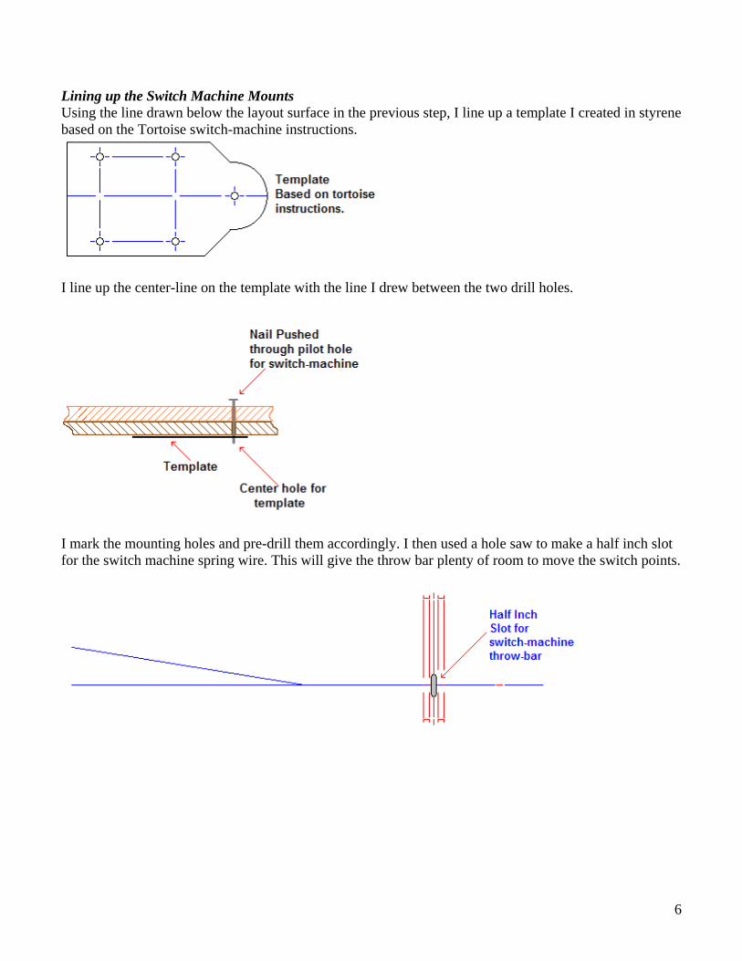
Lining up the Switch Machine Mounts Using the line drawn below the layout surface in the previous step, I line up a template I created in styrene based on the Tortoise switch-machine instructions.
I line up the center-line on the template with the line I drew between the two drill holes.
I mark the mounting holes and pre-drill them accordingly. I then used a hole saw to make a half inch slot for the switch machine spring wire. This will give the throw bar plenty of room to move the switch points.
6

Making a tie template The next step is to glue down the ties. As this can be a tedious step, I created a tie jig using a Fast-Tracks template (you guessed it…) I glued a dual switch template onto a piece of Masonite hardboard. I then glued pieces of balsa wood in the spaces between where the ties go. I insured that the balsa was thinner than the ties I was going to use. This is important as I use painter’s tape to pick up the ties in order once I’ve cut them to size.
The next picture shows the ties all cut and I’ve placed three strips of blue painter’s tape on the ties to hold them in place while I move them to the layout. The blue painter’s tape is less damaging to the wood ties than standard masking tape would be. This is why the balsa separators need to be thinner than the ties so the painter’s tape will stick to all of the ties and not the separators. I also make small pencil marks on the leading edge ties to align them with the center-lines on the layout.
7
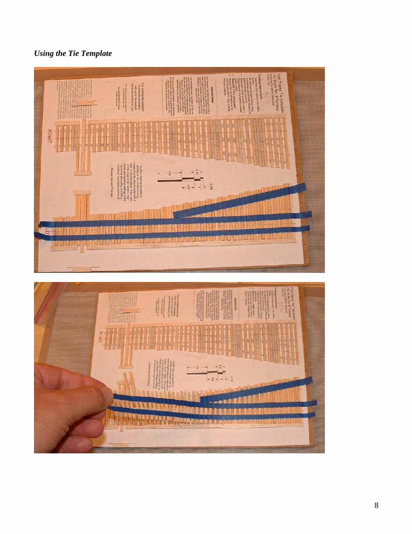
Using the Tie Template
8

Laying the Ties The next picture demonstrates placement of the ties over the pre-glued area. I used white glue for this. Additionally, you can see the lines that were drawn on the Homasote.
Once the ties are laid in place leave the blue painter’s tape in place while the glue dries.
After all of the switches are in place you can fill in between with ties glued in a similar manor. I used non-weathered ties that I stained myself after careful sanding to insure they were consistent across.
9
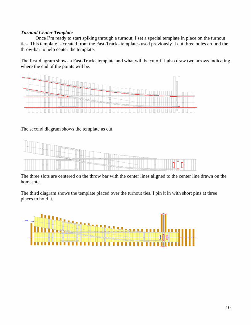
Turnout Center Template Once I’m ready to start spiking through a turnout, I set a special template in place on the turnout ties. This template is created from the Fast-Tracks templates used previously. I cut three holes around the throw-bar to help center the template. The first diagram shows a Fast-Tracks template and what will be cutoff. I also draw two arrows indicating where the end of the points will be.
The second diagram shows the template as cut.
The three slots are centered on the throw bar with the center lines aligned to the center line drawn on the homasote. The third diagram shows the template placed over the turnout ties. I pin it in with short pins at three places to hold it.
10
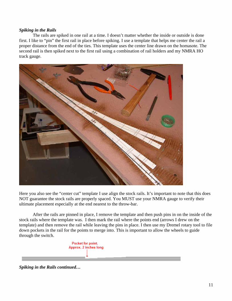
Spiking in the Rails The rails are spiked in one rail at a time. I doesn’t matter whether the inside or outside is done first. I like to “pin” the first rail in place before spiking. I use a template that helps me center the rail a proper distance from the end of the ties. This template uses the center line drawn on the homasote. The second rail is then spiked next to the first rail using a combination of rail holders and my NMRA HO track gauge.
Here you also see the “center cut” template I use align the stock rails. It’s important to note that this does NOT guarantee the stock rails are properly spaced. You MUST use your NMRA gauge to verify their ultimate placement especially at the end nearest to the throw-bar. After the rails are pinned in place, I remove the template and then push pins in on the inside of the stock rails where the template was. I then mark the rail where the points end (arrows I drew on the template) and then remove the rail while leaving the pins in place. I then use my Dremel rotary tool to file down pockets in the rail for the points to merge into. This is important to allow the wheels to guide through the switch.
Spiking in the Rails continued…
11
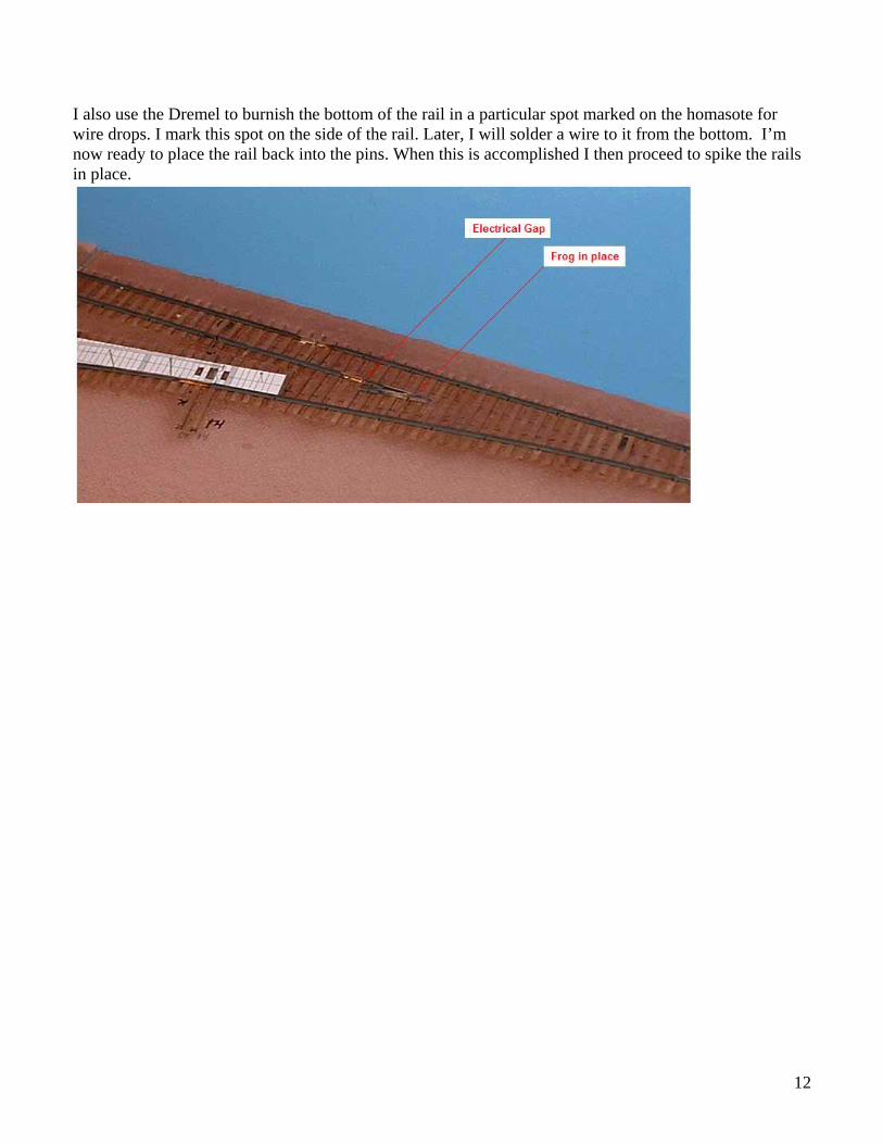
I also use the Dremel to burnish the bottom of the rail in a particular spot marked on the homasote for wire drops. I mark this spot on the side of the rail. Later, I will solder a wire to it from the bottom. I’m now ready to place the rail back into the pins. When this is accomplished I then proceed to spike the rails in place.
12
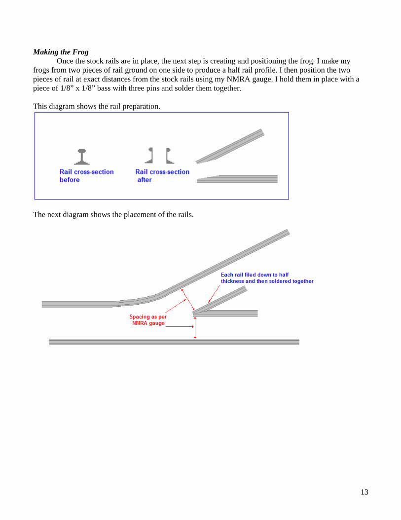
Making the Frog Once the stock rails are in place, the next step is creating and positioning the frog. I make my frogs from two pieces of rail ground on one side to produce a half rail profile. I then position the two pieces of rail at exact distances from the stock rails using my NMRA gauge. I hold them in place with a piece of 1/8” x 1/8” bass with three pins and solder them together. This diagram shows the rail preparation.
The next diagram shows the placement of the rails.
13
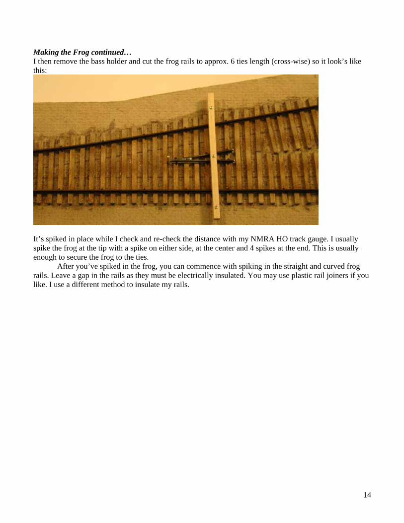
Making the Frog continued… I then remove the bass holder and cut the frog rails to approx. 6 ties length (cross-wise) so it look’s like this:
It’s spiked in place while I check and re-check the distance with my NMRA HO track gauge. I usually spike the frog at the tip with a spike on either side, at the center and 4 spikes at the end. This is usually enough to secure the frog to the ties.
After you’ve spiked in the frog, you can commence with spiking in the straight and curved frog rails. Leave a gap in the rails as they must be electrically insulated. You may use plastic rail joiners if you like. I use a different method to insulate my rails.
14

The Point-Closure-Wing rails The next step is to create the point-closure-wing rails. I use my Point-Frog tool to create the point
end first. You can also use a set of mending plates bolted together with the center place at an angle to provide the filing angle.
I attach the point end to its corresponding slot in the stock rail, then a grab the rail approx. ½” from the frog and bend out. This bend will form the wing rail part. I then cut the end off about six ties long. I also file the end at a 45 degree angle to allow me to solder the wing rail to the frog later. The next step is to spike the point-closure-wing rail down. Again, use your NMRA gauge to insure the rail is accurately spaced from its corresponding stock rail. When the rail is spiked down, I then add two spikes to hold down the wing rail. Check your NMRA gauge for the right distance between the wing and from rails by using the “no-go” part of the gauge. (See your NMRA gauge’s instructions)
After the straight point-closure-wing rail is spike in, proceed to do the curved one the same way. I’ve found no difference in which rail you start with.
15

The Point-Closure-Wing rails continued… This is what the turn-out will look like so far. I have intentionally left out a number of spikes; normally I spike the point-closure-wing rails in at every other tie. I stop spiking approx. 3 inches from the point to give the point rail plenty of spring for the switch machine.
16

Creating the Throw-Bar The next step is to create the throw-bar. I use a piece of turn-out length tie to create mine. This picture shows one in the process of being installed.
The throw-bar should look like this illustration:
The first step in creating this is to cut the turn-out length tie to the correct length using the turn-out template:
17

Creating the Throw-Bar continued… Then you need to sand the tie until it glides easily under the spiked rails of your turn-out. If it doesn’t move easily, sand it some more but be careful not to sand it down to nothing.
After it’s sanded, we need to make the marks for the slots:
Note the lines drawn at the outside edge of both points as well as the cross at the center line of the template. You will note that this is not exactly centered and is in fact closer to the straight stock rail than the curved one. This is correct; don’t try to center it just go with the template.
18

Creating the Throw-Bar continued… The next step is to file the slots for the brass strips that the point rails will eventually be soldered to. Set the file with its outside edge on the line you have drawn in the previous step.
Then file the slot on the bottom of the throw-bar.
Repeat
19

Creating the Throw-Bar continued… Repeat these steps on the other slot.
Finally, use your pin-vise to drill a 0.028 (#70) hole in the center mark made earlier.
20
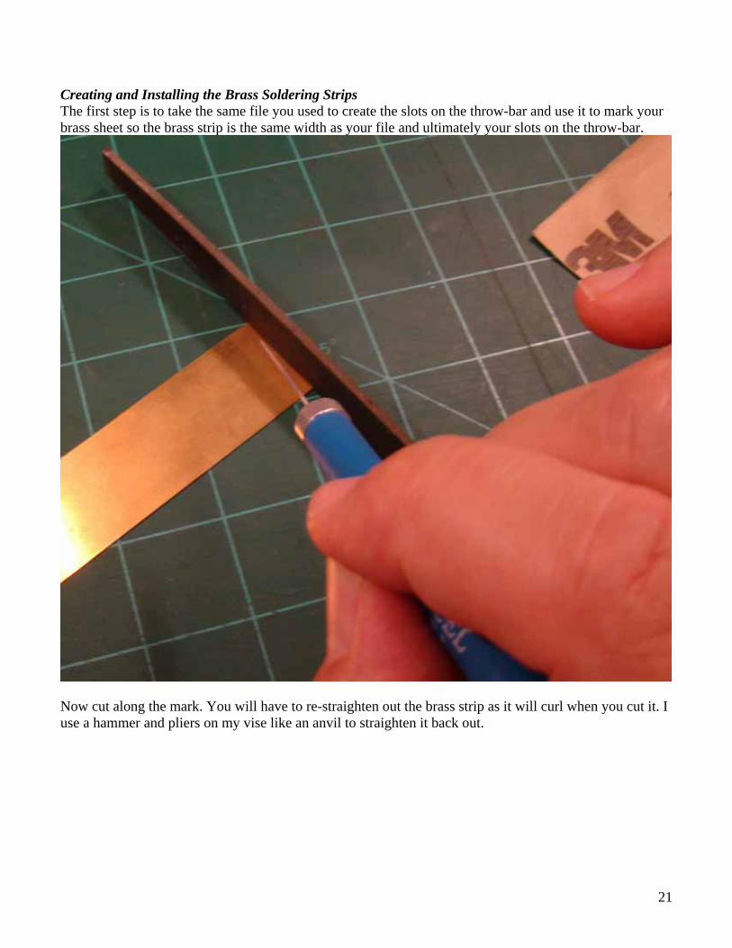
Creating and Installing the Brass Soldering Strips The first step is to take the same file you used to create the slots on the throw-bar and use it to mark your brass sheet so the brass strip is the same width as your file and ultimately your slots on the throw-bar.
Now cut along the mark. You will have to re-straighten out the brass strip as it will curl when you cut it. I use a hammer and pliers on my vise like an anvil to straighten it back out.
21
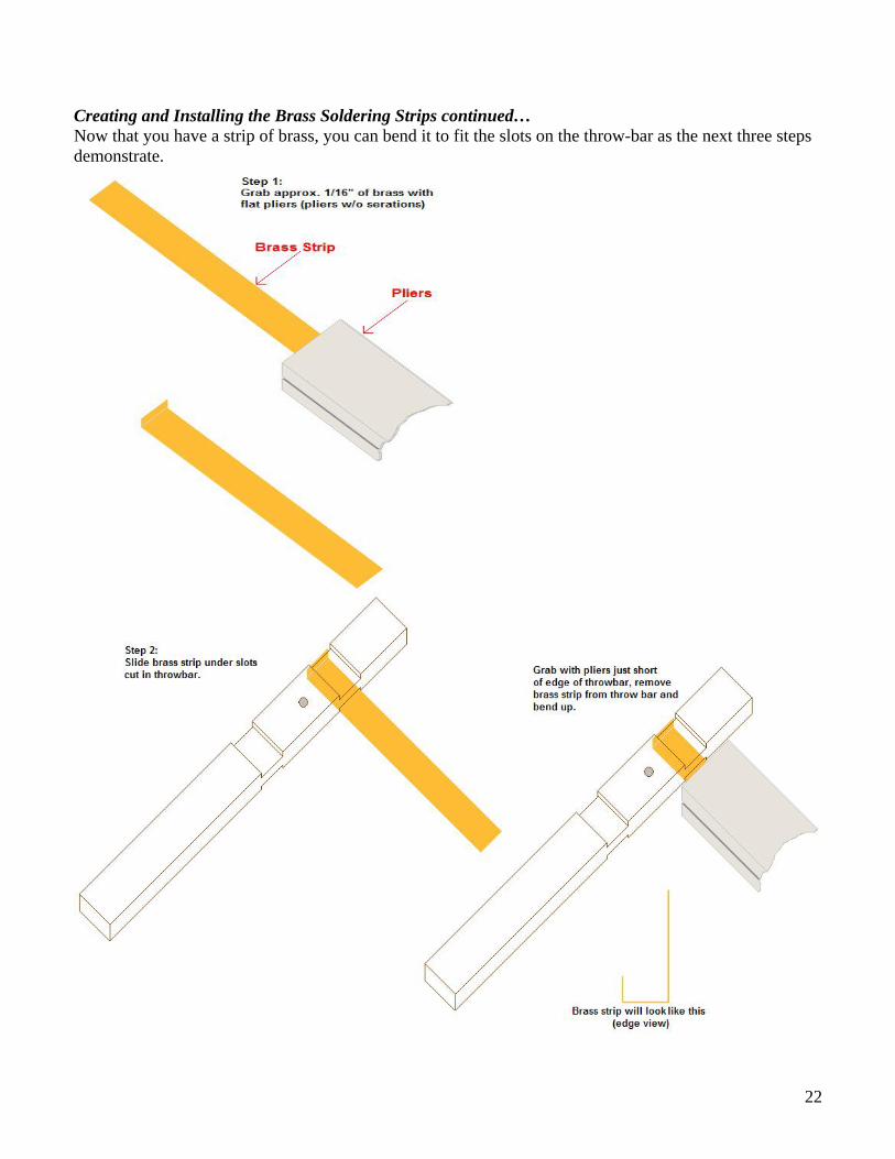
Creating and Installing the Brass Soldering Strips continued… Now that you have a strip of brass, you can bend it to fit the slots on the throw-bar as the next three steps demonstrate.
22
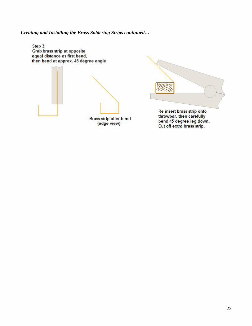
Creating and Installing the Brass Soldering Strips continued…
23
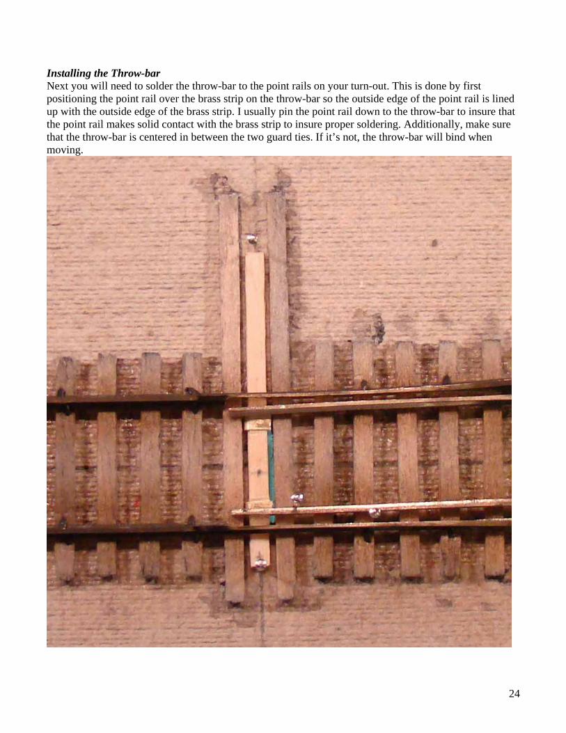
Installing the Throw-bar Next you will need to solder the throw-bar to the point rails on your turn-out. This is done by first positioning the point rail over the brass strip on the throw-bar so the outside edge of the point rail is lined up with the outside edge of the brass strip. I usually pin the point rail down to the throw-bar to insure that the point rail makes solid contact with the brass strip to insure proper soldering. Additionally, make sure that the throw-bar is centered in between the two guard ties. If it’s not, the throw-bar will bind when moving.
24

Reinforcing the Tortoise Spring Wire You need a little bit stronger wire to throw a turnout that doesn’t use hinged point rails. To accomplish this you can use thicker wire or you try what I do. I use a piece of 1/16” brass tubing 2 5/8” long around the standard 0.025 wire supplied by Tortoise. This allows me to use the existing hole in the Tortoise machine’s throw arm. Additionally, I don’t need a larger hole in my throw-bars that could weaken them.
This example shows the .025 wire bent to the diagram Tortoise provides and also shows the brass tubing also bent to the diagram without the final sharp bend where the wire goes into the machine’s throw arm. I then slip the brass tubing over the .025 wire using a pliers to hold the brass and another to carefully press the wire in. It will resist a little at firs, just take your time and don’t bend the .025 wire.
25

Then for installation, thread the top wire end into the hole on the throw-bar (this can be tricky) then slide the plastic fulcrum over the wire/brass combination and then slide the fulcrum into position on the switch machine and finally connect the small end of the wire to the machine’s arm. Tighten down the screw provided with your tortoise switch machine.
26

27
That concludes my approach to laying turnouts in place on your layout. I hope you have success if you try this.
Brad Morneau