hand valves, gauge valves & manifolds - hoke series manifolds_hand_valves_gauges_catalog... ·...
TRANSCRIPT

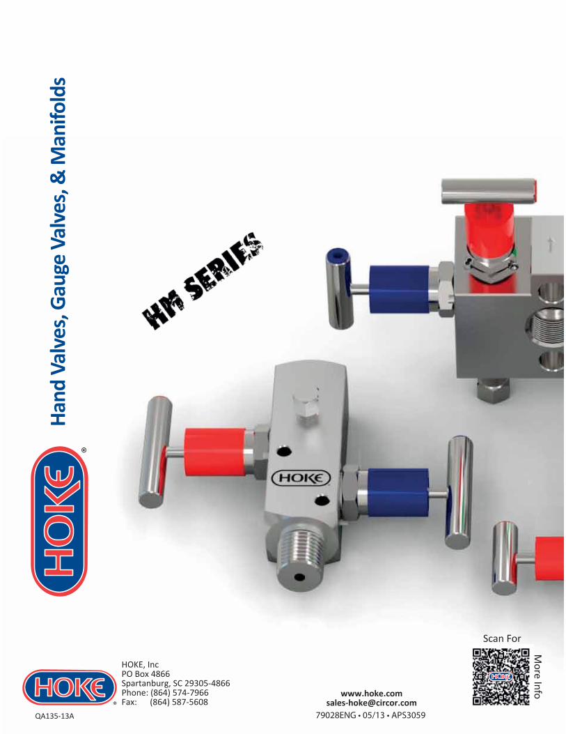
Hand Valves, Gauge Valves & Manifolds
Index
Technical Specifications .............................................................................. Pg.2
NPT High Tolerance Thread Specifications................................................... Pg.3
Integral GYROLOK® ..................................................................................... Pg.4
How To Order / Optional Extras .................................................................. Pg.6,10,21
Hand Valves................................................................................................ Pg.5
Gauge Valves .............................................................................................. Pg.7
Manifolds................................................................................................... Pg.11
Mounting Bracket Kits ............................................................................... Pg.22
Guidance On Use........................................................................................ Pg.25
INDEX / USER RESPONSIBILITY Hand Valves, Gauge Valves & Manifolds
1
WARNING – For Your Safety—USER RESPONSIBILITY
FAILURE OR IMPROPER SELECTION OR IMPROPER USE OF THE PRODUCTS DESCRIBED HEREIN OR RELATED ITEMS CAN CAUSE DEATH, PERSONAL INJURY AND PROPERTY DAMAGE.This document and other information from CIRCOR Instrumentation Technologies (CIT), its subsidiaries and authorized distributors provide product or system options for further investigation by users having technical expertise. IT IS SOLELY THE RESPONSIBILITY OF THE SYSTEM DESIGNER AND USER TO SELECT PRODUCTS SUITABLE FOR THEIR SPECIFIC APPLICATION REQUIREMENTS AND TO ENSURE PROPER INSTALLATION, OPERATION AND MAINTENANCE OF THESE PRODUCTS, MATERIAL COMPATABILITY, PRODUCT RATINGS AND APPLICATION DETAILS SHOULD BE CONSIDERED IN THE SELECTION.The user through its own analysis and testing, is solely responsible for making the final selection of the system and components and assuring that all performance, endurance, maintenance, safety and warning requirements of the application are met. The user must analyze all aspects of the application; follow applicable industry standards; and follow the information concerning the product in the current product catalog an in any other materials provided by CIT or authorized distributors.To the extent that CIT or its subsidiaries or authorized distributors provide component or system options based upon data or specifications provided by the user, the user is responsible for determining that such data and specifications are suitable and sufficient for all applications and reasonably foreseeable uses of the components or systems.
(Please refer to our Guidance on Use of Equipment document). Offer of Sale
The items described in this document are hereby offered for sale by CIRCOR Instrumentation Technologies (CIT), its subsidiaries or its distributors. Any order accepted by CIT will be subject to our terms and conditions of sale, copy available on www.hoke.com, or by request.
QA135-13A
HOKE, IncPO Box 4866 Spartanburg, SC 29305-4866Phone: (864) 574-7966 Fax: (864) 587-5608
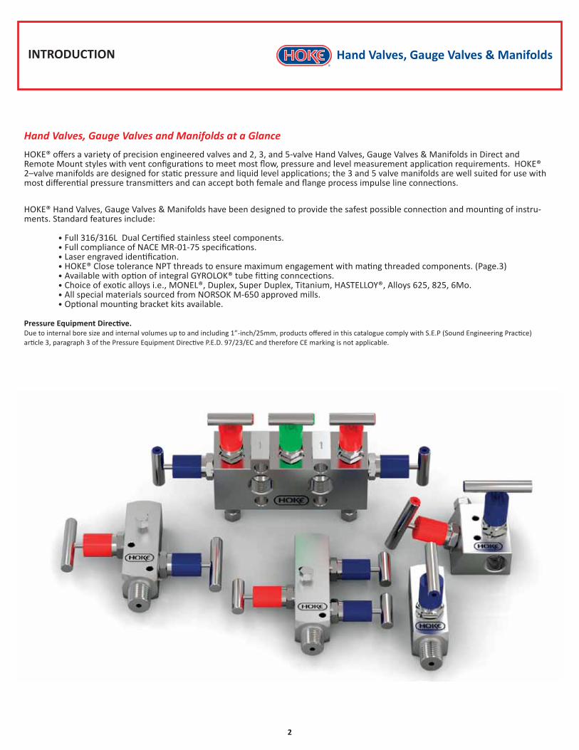
Hand Valves, Gauge Valves and Manifolds at a Glance
HOKE® offers a variety of precision engineered valves and 2, 3, and 5-valve Hand Valves, Gauge Valves & Manifolds in Direct and Remote Mount styles with vent configurations to meet most flow, pressure and level measurement application requirements. HOKE® 2–valve manifolds are designed for static pressure and liquid level applications; the 3 and 5 valve manifolds are well suited for use with most differential pressure transmitters and can accept both female and flange process impulse line connections.
HOKE® Hand Valves, Gauge Valves & Manifolds have been designed to provide the safest possible connection and mounting of instru-ments. Standard features include:
• Full 316/316L Dual Certified stainless steel components. • Full compliance of NACE MR-01-75 specifications. • Laser engraved identification. • HOKE® Close tolerance NPT threads to ensure maximum engagement with mating threaded components. (Page.3) • Available with option of integral GYROLOK® tube fitting conncections. • Choice of exotic alloys i.e., MONEL®, Duplex, Super Duplex, Titanium, HASTELLOY®, Alloys 625, 825, 6Mo. • All special materials sourced from NORSOK M-650 approved mills. • Optional mounting bracket kits available.
Pressure Equipment Directive. Due to internal bore size and internal volumes up to and including 1”-inch/25mm, products offered in this catalogue comply with S.E.P (Sound Engineering Practice) article 3, paragraph 3 of the Pressure Equipment Directive P.E.D. 97/23/EC and therefore CE marking is not applicable.
INTRODUCTION Hand Valves, Gauge Valves & Manifolds
2

Hand Valves, Gauge Valves & Manifolds
3
STANDARD VALVE HEAD ASSEMBLYTechnical Specifications
Removable T-bar handleaids low torque operation
Color coded dust cap on stem preventsingress of contamination
& protects actuating threads
Stem has rolled threads for action, strength, and long life.
Stem threads above packing, no process contamination or lube washout
One piece non-rotating stem tip joint located above packing, cannot work free
Metal to metal seal with body suitable for high pressure temperature applications.
No need for O-ring seals
Gland adjuster packing seal can be externally adjusted in service
Packing PTFE (Standard) / GRAFOIL® PACKING (Optional) is below the stem threads to isolate
threads from process media
Dead stem through packing eases operation and has less packing wear
Stem has back seat for added security
Precision Machined Hard Stem Tip of stainless steel provides consistent shut-off
Safety locknut
Color coded dust plug
OTHER FEATURES• Valves are supplied to NACE MR-01-75 specification.• Needle valve & and block and bleed valve available in right angled form.• Hydrostatically tested to 1.5 times maximum working pressure.• Wide variety of process connections available by arrangement.• Bleed & blind plugs are available.• Isolating trim as standard, metering trim available on request.• Panel mounting valve available on request.• PCTFE Soft tip option available for special application (Max working temperature = 120° C).• All valves and manifolds are individually boxed for protection and storage.• Laser engraved identification. • Valves have trace code on body with original mill certificates available all to EN 10204-3.1.• All special materials sourced from NORSOK M-650 approved mills.• Ø 4.76 Standard thru bore (CV = 0.4) Fully open.• Bonnet locking pin safely locks the bonnet to body.
Compression Ring
PCTFE Soft Stem Tip(Optional)
PRESSURE TEMPERATURE CHARTPTFE PACKING Maximum pressure 6000 psi (413 bar) at 212° F (100° C)Maximum pressure 4000 psi (275 bar) at 392° F (200° C)(PTFE packing rated to maximum temperature of 392° F (200° C))GRAFOIL® PACKING Maximum pressure 6000 psi (413 bar) at 212° F (100° C)Maximum pressure 3300 psi (230 bar) at 842° F (450° C)
8702 (600)
7252 (500)
5802 (400)
4351 (300)
2901 (200)
1450 (100)
0
0 212(100)
Temperature Fahrenheit (Celsius)
Pres
sure
psi
(bar
)
392(200)
572(300)
752(400)
932(500)
1112(600)
10153 (700)
68(20)
PTFE Packing With Soft Stem Tip
Note: PCTFE Soft Stem Tip (Option) is only available with PTFE Packing
GRAFOIL® PACKING
PTFE PACKING
NPT High Tolerance Thread Specifications
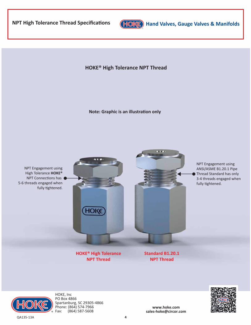
NPT Engagement usingANSI/ASME B1.20.1 PipeThread Standard has only 3-4 threads engaged whenfully tightened.
NPT Engagement usingHigh Tolerance HOKE®NPT Connections has
5-6 threads engaged whenfully tightened.
HOKE® High ToleranceNPT Thread
Standard B1.20.1NPT Thread
Note: Graphic is an illustration only
HOKE® High Tolerance NPT Thread
Hand Valves, Gauge Valves & Manifolds
4QA135-13A
HOKE, IncPO Box 4866 Spartanburg, SC 29305-4866Phone: (864) 574-7966 Fax: (864) 587-5608

Integral GYROLOK® Tube Fitting Connection
HOKE® Integral GYROLOK® Tube Fitting Connection
Hand Valves, Gauge Valves & Manifolds
5
Note: Graphic is an illustration only – please consult HOKE® for details
The HOKE® range of hand valves, gauge valves and manifolds are available with the option of the integral GYROLOK® tube fitting connections. The integral GYROLOK® tube fitting connection is machined directly into the body of the valve or manifold, allowing tubing to be directly connected without the use of traditional threaded (NPT, BSP) connections. The integral GYROLOK® connection provides a safer connection system for high pressure, severe, steam or sour gas service where leakage has dangerous consequences.
• Eliminates traditional threaded tubing connections• Provides a safer and more consistent tube connection• Saves assembly time during field assembly • Reduces potential leak paths • No need for sealing tape or liquid sealing compounds • Fully field maintainable • Successfully used for over 20 years in many offshore applications• Available in 10mm metric tube connections• Available in ⅜”inch & ½”inch imperial tube connections
Front Ferrule
Rear Ferrule
Nut
Tube
Valve / Manifold Body
QA135-13A
HOKE, IncPO Box 4866 Spartanburg, SC 29305-4866Phone: (864) 574-7966 Fax: (864) 587-5608

Hand Valves, Gauge Valves & Manifolds
6
SINGLE BLOCK HAND VALVE
MODEL-HM25
Also available in a range of other materials and options (See HOW TO ORDER Data Sheet Pg.7).
ApplicationHigh integrity instrument isolation of pressure gauges and pressure transmitters.
VENTEQUALIZE
Weight=1.1 lbs(0.5 kg)
ISOLATE Blue
Red
Green
Valve Shown with ½” NPT Inlet & Outlet
Dimensions shown in inches (millimetres) are for reference only and are subject to change.
Instrument
Process In
HM25 1 1 F 8 6MO AAHM25 1 1 F 8 6MO AA
Hand Valves, Gauge Valves & Manifolds
7
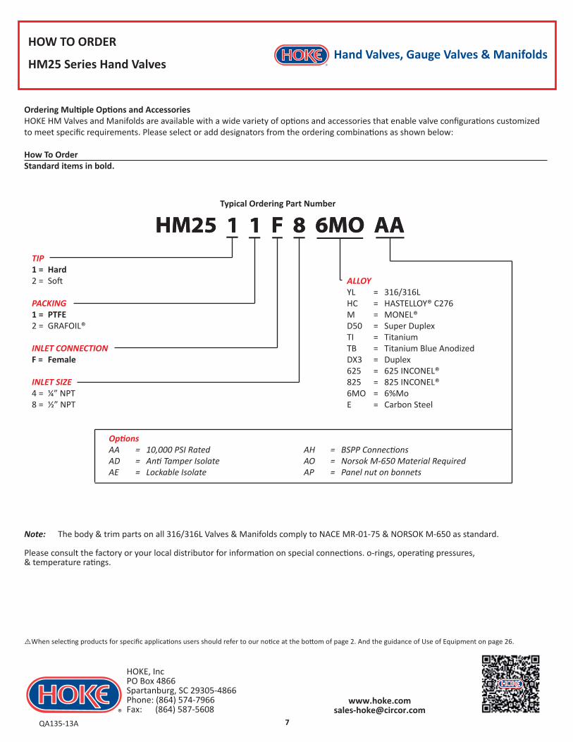
HOW TO ORDER
HM25 Series Hand Valves
TIP1 = Hard2 = Soft
PACKING1 = PTFE2 = GRAFOIL®
INLET CONNECTIONF = Female
INLET SIZE4 = ¼” NPT8 = ½” NPT
Ordering Multiple Options and AccessoriesHOKE HM Valves and Manifolds are available with a wide variety of options and accessories that enable valve configurations customized to meet specific requirements. Please select or add designators from the ordering combinations as shown below:
How To OrderStandard items in bold.
Note: The body & trim parts on all 316/316L Valves & Manifolds comply to NACE MR-01-75 & NORSOK M-650 as standard.
Please consult the factory or your local distributor for information on special connections. o-rings, operating pressures, & temperature ratings.
Typical Ordering Part Number
QA135-13A
HOKE, IncPO Box 4866 Spartanburg, SC 29305-4866Phone: (864) 574-7966 Fax: (864) 587-5608
ALLOYYL = 316/316L HC = HASTELLOY® C276M = MONEL®D50 = Super DuplexTI = TitaniumTB = Titanium Blue AnodizedDX3 = Duplex625 = 625 INCONEL®825 = 825 INCONEL®6MO = 6%MoE = Carbon Steel
AH = BSPP ConnectionsAO = Norsok M-650 Material RequiredAP = Panel nut on bonnets
OptionsAA = 10,000 PSI RatedAD = Anti Tamper IsolateAE = Lockable Isolate
⚠When selecting products for specific applications users should refer to our notice at the bottom of page 2. And the guidance of Use of Equipment on page 26.
Hand Valves, Gauge Valves & Manifolds
8
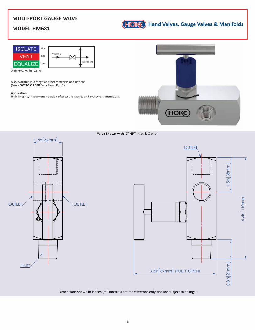
MULTI-PORT GAUGE VALVE
MODEL-HM681
Also available in a range of other materials and options (See HOW TO ORDER Data Sheet Pg.11).
ApplicationHigh integrity instrument isolation of pressure gauges and pressure transmitters.
Valve Shown with ½” NPT Inlet & Outlet
Dimensions shown in inches (millimetres) are for reference only and are subject to change.
Process In
Instrument
Weight=1.76 lbs(0.8 kg)
EQUALIZE
ISOLATE Blue
Red
Green
VENT

Hand Valves, Gauge Valves & Manifolds
9
Also available in a range of other materials and options (See HOW TO ORDER Data Sheet Pg.11).
ApplicationHigh integrity instrument isolation of pressure gauges and pressure transmitters.
VENTEQUALIZE
Weight=2.2 lbs(1.0 kg)
ISOLATE Blue
Red
Green
Valve Shown with ½” NPT Inlet & Outlet & ¼”NPT Vent Plug (Supplied loose)
Dimensions for 6K shown in inches (millimetres) are for reference only and are subject to change.
IsolateProcess
Instrument
Vent
SINGLE BLOCK & BLEED GAUGE VALVE
MODEL-HM682
QA135-13A
HOKE, IncPO Box 4866 Spartanburg, SC 29305-4866Phone: (864) 574-7966 Fax: (864) 587-5608
Hand Valves, Gauge Valves & Manifolds
10
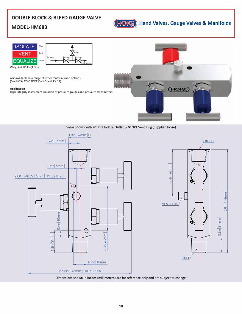
DOUBLE BLOCK & BLEED GAUGE VALVE
MODEL-HM683
Also available in a range of other materials and options (See HOW TO ORDER Data Sheet Pg.11).
ApplicationHigh integrity instrument isolation of pressure gauges and pressure transmitters.
VENTEQUALIZE
Weight=2.86 lbs(1.3 kg)
ISOLATE Blue
Red
Green
Valve Shown with ½” NPT Inlet & Outlet & ¼”NPT Vent Plug (Supplied loose)
Dimensions shown in inches (millimetres) are for reference only and are subject to change.
Process
Instrument
Isolate
Vent
Isolate
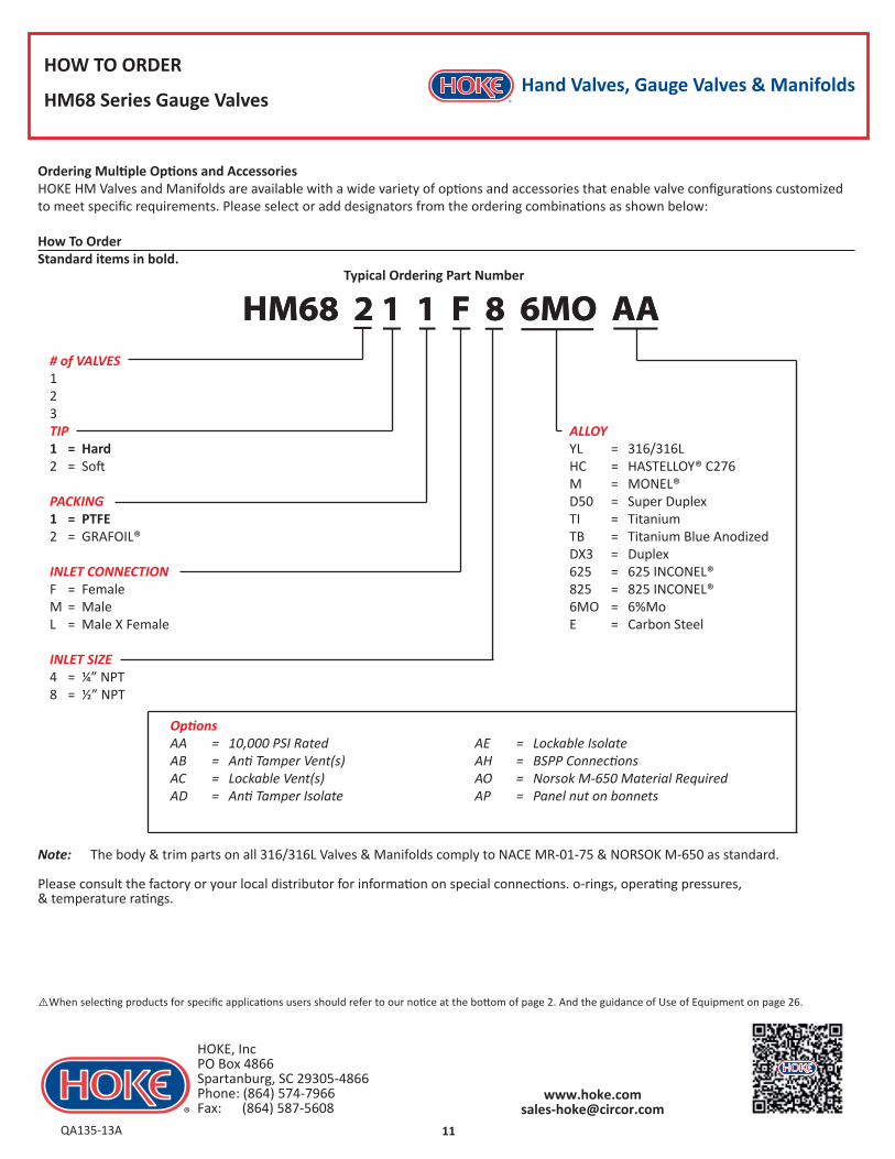
HM68 2 1 1 F 8 6MO AAHM68 2 1 1 F 8 6MO AA
Hand Valves, Gauge Valves & Manifolds
11
HOW TO ORDER
HM68 Series Gauge Valves
# of VALVES123TIP1 = Hard2 = Soft
PACKING1 = PTFE2 = GRAFOIL®
INLET CONNECTIONF = FemaleM = MaleL = Male X Female
INLET SIZE4 = ¼” NPT8 = ½” NPT
Ordering Multiple Options and AccessoriesHOKE HM Valves and Manifolds are available with a wide variety of options and accessories that enable valve configurations customized to meet specific requirements. Please select or add designators from the ordering combinations as shown below:
How To OrderStandard items in bold.
ALLOYYL = 316/316L HC = HASTELLOY® C276M = MONEL®D50 = Super DuplexTI = TitaniumTB = Titanium Blue AnodizedDX3 = Duplex625 = 625 INCONEL®825 = 825 INCONEL®6MO = 6%MoE = Carbon Steel
Note: The body & trim parts on all 316/316L Valves & Manifolds comply to NACE MR-01-75 & NORSOK M-650 as standard.
Please consult the factory or your local distributor for information on special connections. o-rings, operating pressures, & temperature ratings.
Typical Ordering Part Number
QA135-13A
HOKE, IncPO Box 4866 Spartanburg, SC 29305-4866Phone: (864) 574-7966 Fax: (864) 587-5608
AE = Lockable IsolateAH = BSPP ConnectionsAO = Norsok M-650 Material RequiredAP = Panel nut on bonnets
OptionsAA = 10,000 PSI RatedAB = Anti Tamper Vent(s)AC = Lockable Vent(s)AD = Anti Tamper Isolate
⚠When selecting products for specific applications users should refer to our notice at the bottom of page 2. And the guidance of Use of Equipment on page 26.
Hand Valves, Gauge Valves & Manifolds
12
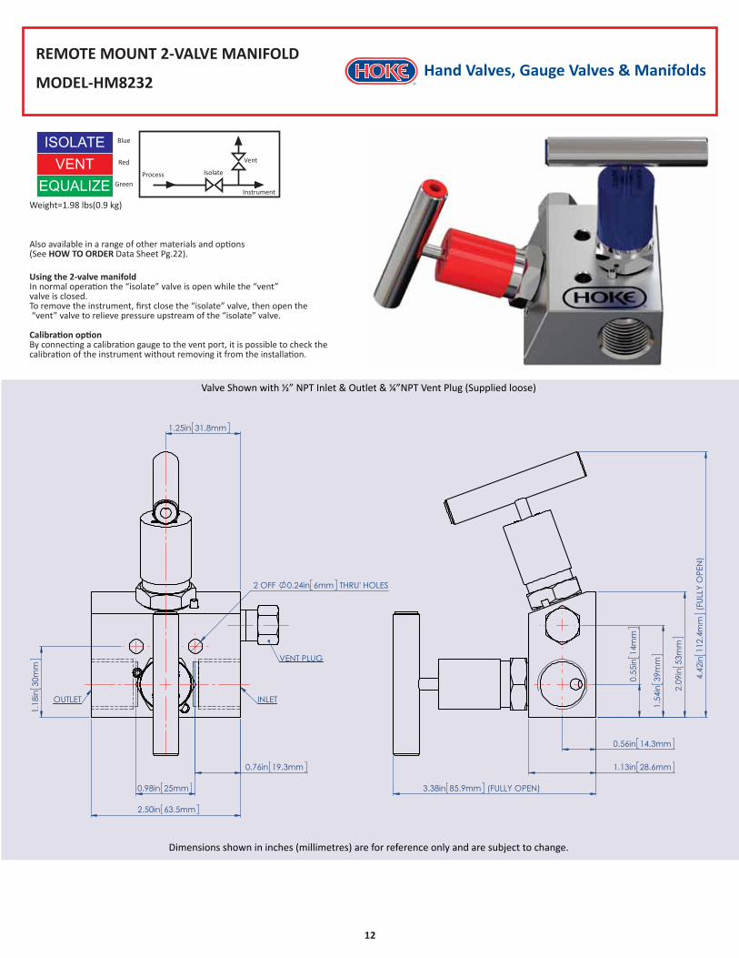
REMOTE MOUNT 2-VALVE MANIFOLD
MODEL-HM8232
Also available in a range of other materials and options (See HOW TO ORDER Data Sheet Pg.22).
Valve Shown with ½” NPT Inlet & Outlet & ¼”NPT Vent Plug (Supplied loose)
Dimensions shown in inches (millimetres) are for reference only and are subject to change.
Process
Instrument
Isolate
Vent
VENTVENT
EQUALIZEWeight=1.98 lbs(0.9 kg)
ISOLATE Blue
Red
Green
Using the 2-valve manifoldIn normal operation the “isolate” valve is open while the “vent” valve is closed.To remove the instrument, first close the “isolate” valve, then open the “vent” valve to relieve pressure upstream of the “isolate” valve.
Calibration optionBy connecting a calibration gauge to the vent port, it is possible to check the calibration of the instrument without removing it from the installation.
Hand Valves, Gauge Valves & Manifolds
13
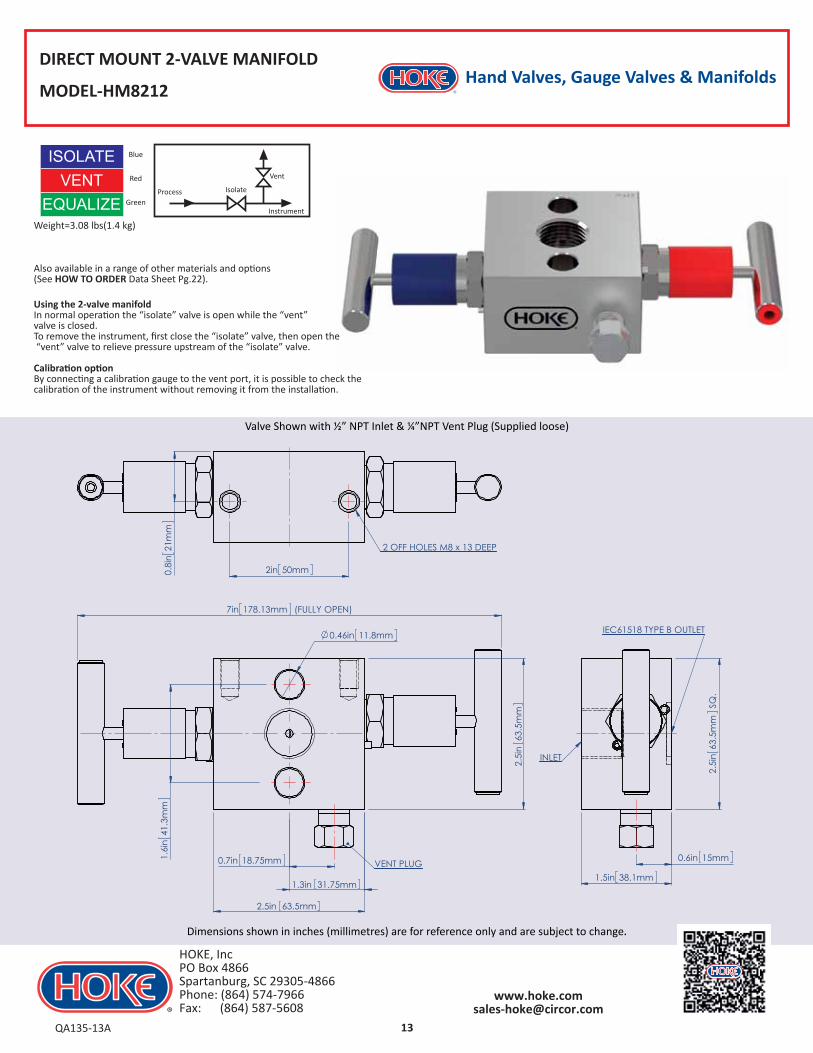
DIRECT MOUNT 2-VALVE MANIFOLD
MODEL-HM8212
Also available in a range of other materials and options (See HOW TO ORDER Data Sheet Pg.22).
VENTEQUALIZE
Weight=3.08 lbs(1.4 kg)
ISOLATE Blue
Red
Green
Valve Shown with ½” NPT Inlet & ¼”NPT Vent Plug (Supplied loose)
Dimensions shown in inches (millimetres) are for reference only and are subject to change.
Process
Instrument
Isolate
Vent
Using the 2-valve manifoldIn normal operation the “isolate” valve is open while the “vent” valve is closed.To remove the instrument, first close the “isolate” valve, then open the “vent” valve to relieve pressure upstream of the “isolate” valve.
Calibration optionBy connecting a calibration gauge to the vent port, it is possible to check the calibration of the instrument without removing it from the installation.
QA135-13A
HOKE, IncPO Box 4866 Spartanburg, SC 29305-4866Phone: (864) 574-7966 Fax: (864) 587-5608
Hand Valves, Gauge Valves & Manifolds
14
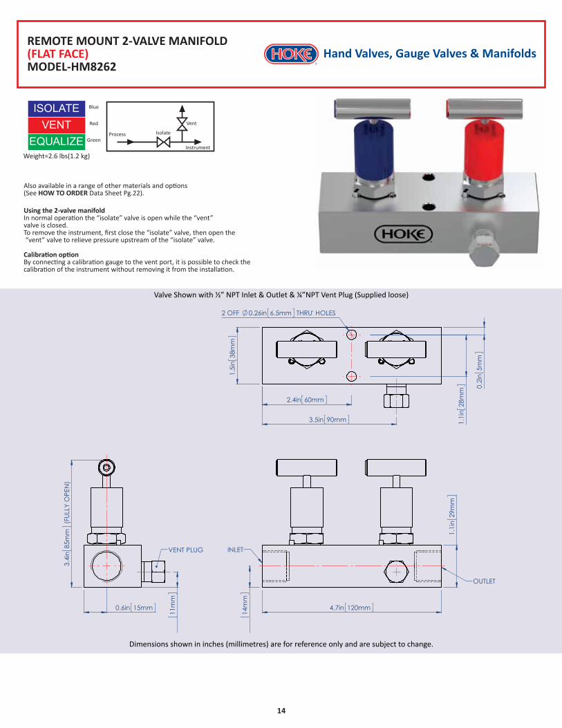
REMOTE MOUNT 2-VALVE MANIFOLD(FLAT FACE)MODEL-HM8262
Also available in a range of other materials and options (See HOW TO ORDER Data Sheet Pg.22).
Valve Shown with ½” NPT Inlet & Outlet & ¼”NPT Vent Plug (Supplied loose)
Dimensions shown in inches (millimetres) are for reference only and are subject to change.
Process
Instrument
Isolate
VentVENTEQUALIZE
Weight=2.6 lbs(1.2 kg)
ISOLATE Blue
Red
Green
Using the 2-valve manifoldIn normal operation the “isolate” valve is open while the “vent” valve is closed.To remove the instrument, first close the “isolate” valve, then open the “vent” valve to relieve pressure upstream of the “isolate” valve.
Calibration optionBy connecting a calibration gauge to the vent port, it is possible to check the calibration of the instrument without removing it from the installation.
Hand Valves, Gauge Valves & Manifolds
15
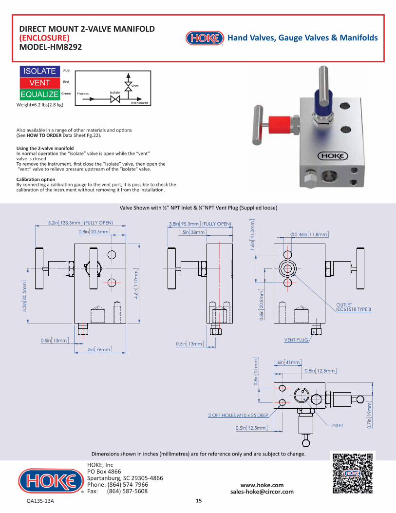
DIRECT MOUNT 2-VALVE MANIFOLD(ENCLOSURE)MODEL-HM8292
Also available in a range of other materials and options (See HOW TO ORDER Data Sheet Pg.22).
VENTEQUALIZE
Weight=6.2 lbs(2.8 kg)
ISOLATE Blue
Red
Green
Valve Shown with ½” NPT Inlet & ¼”NPT Vent Plug (Supplied loose)
Dimensions shown in inches (millimetres) are for reference only and are subject to change.
Process
Instrument
Isolate
Vent
Using the 2-valve manifoldIn normal operation the “isolate” valve is open while the “vent” valve is closed.To remove the instrument, first close the “isolate” valve, then open the “vent” valve to relieve pressure upstream of the “isolate” valve.
Calibration optionBy connecting a calibration gauge to the vent port, it is possible to check the calibration of the instrument without removing it from the installation.
QA135-13A
HOKE, IncPO Box 4866 Spartanburg, SC 29305-4866Phone: (864) 574-7966 Fax: (864) 587-5608
Hand Valves, Gauge Valves & Manifolds
16
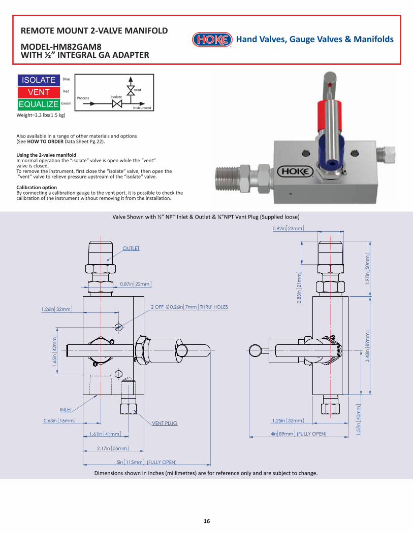
REMOTE MOUNT 2-VALVE MANIFOLD
MODEL-HM82GAM8WITH ½” INTEGRAL GA ADAPTER
Also available in a range of other materials and options (See HOW TO ORDER Data Sheet Pg.22).
VENTEQUALIZE
Weight=3.3 lbs(1.5 kg)
ISOLATE Blue
Red
Green
Valve Shown with ½” NPT Inlet & Outlet & ¼”NPT Vent Plug (Supplied loose)
Dimensions shown in inches (millimetres) are for reference only and are subject to change.
Process
Instrument
Isolate
Vent
Using the 2-valve manifoldIn normal operation the “isolate” valve is open while the “vent” valve is closed.To remove the instrument, first close the “isolate” valve, then open the “vent” valve to relieve pressure upstream of the “isolate” valve.
Calibration optionBy connecting a calibration gauge to the vent port, it is possible to check the calibration of the instrument without removing it from the installation.
Hand Valves, Gauge Valves & Manifolds
17
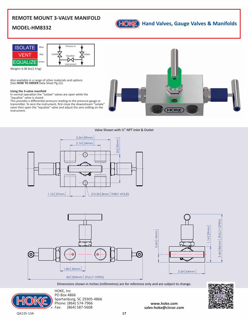
REMOTE MOUNT 3-VALVE MANIFOLD
MODEL-HM8332
Also available in a range of other materials and options (See HOW TO ORDER Data Sheet Pg.22).
VENTEQUALIZE
Weight=3.08 lbs(1.4 kg)
ISOLATE Blue
Red
Green
Valve Shown with ½” NPT Inlet & Outlet
Dimensions shown in inches (millimetres) are for reference only and are subject to change.
Using the 3-valve manifoldIn normal operation the “isolate” valves are open while the “equalize” valve is closed. This provides a differential pressure reading to the pressure gauge or transmitter. To zero the instrument, first close the downstream “isolate” valve then open the “equalize” valve and adjust the zero setting on the instrument.
Instrument
EqualizeIsolateIsolate
Process In
QA135-13A
HOKE, IncPO Box 4866 Spartanburg, SC 29305-4866Phone: (864) 574-7966 Fax: (864) 587-5608
Hand Valves, Gauge Valves & Manifolds
18
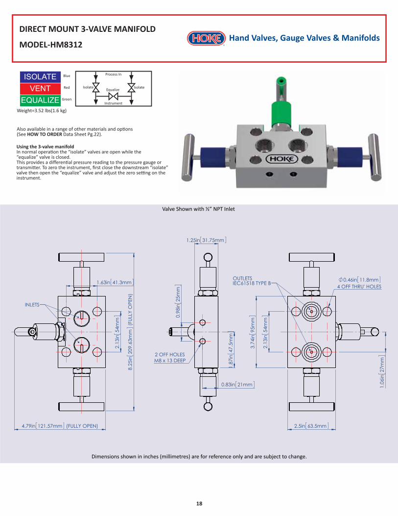
DIRECT MOUNT 3-VALVE MANIFOLD
MODEL-HM8312
Also available in a range of other materials and options (See HOW TO ORDER Data Sheet Pg.22).
VENTEQUALIZE
Weight=3.52 lbs(1.6 kg)
ISOLATE Blue
Red
Green
Valve Shown with ½” NPT Inlet
Dimensions shown in inches (millimetres) are for reference only and are subject to change.
Instrument
EqualizeIsolateIsolate
Process In
Using the 3-valve manifoldIn normal operation the “isolate” valves are open while the “equalize” valve is closed. This provides a differential pressure reading to the pressure gauge or transmitter. To zero the instrument, first close the downstream “isolate” valve then open the “equalize” valve and adjust the zero setting on the instrument.
Hand Valves, Gauge Valves & Manifolds
19
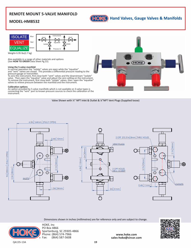
REMOTE MOUNT 5-VALVE MANIFOLD
MODEL-HM8532
Also available in a range of other materials and options (See HOW TO ORDER Data Sheet Pg.22).
VENTEQUALIZE
Weight=5.95 lbs(2.7 kg)
ISOLATE Blue
Red
Green
Valve Shown with ½” NPT Inlet & Outlet & ¼”NPT Vent Plugs (Supplied loose)
Dimensions shown in inches (millimetres) are for reference only and are subject to change.
Using the 5-valve manifoldIn normal operation the “isolate” valves are open while the “equalize” and “vent” valves are closed. This provides a differential pressure reading to the pressure gauge or transmitter.To zero the instrument, first close both “vent” valves and the downstream “isolate” valve. Then open the “equalize” valve and adjust the zero setting on the instrument.To remove the instrument, first close both “isolate” valves, then open the “equalize” valves to relieve pressure between the manifold and the instrument.
Calibration optionsAn option provided by 5-valve manifolds which is not available on 3-valve types is connecting the “vent” port to known pressure sources to check the calibration of the instrument.
VentInstrument
Process In
Vent
EqualizeIsolate Isolate
QA135-13A
HOKE, IncPO Box 4866 Spartanburg, SC 29305-4866Phone: (864) 574-7966 Fax: (864) 587-5608
Hand Valves, Gauge Valves & Manifolds
20
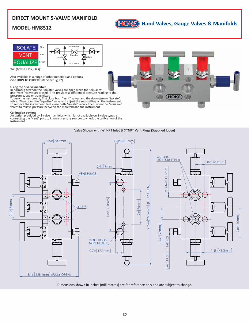
DIRECT MOUNT 5-VALVE MANIFOLD
MODEL-HM8512
VENTEQUALIZE
Weight=6.17 lbs(2.8 kg)
ISOLATE Blue
Red
Green
Valve Shown with ½” NPT Inlet & ¼”NPT Vent Plugs (Supplied loose)
Dimensions shown in inches (millimetres) are for reference only and are subject to change.
VentInstrument
Process In
Vent
EqualizeIsolate Isolate
Also available in a range of other materials and options (See HOW TO ORDER Data Sheet Pg.22).
Using the 5-valve manifoldIn normal operation the “isolate” valves are open while the “equalize” and “vent” valves are closed. This provides a differential pressure reading to the pressure gauge or transmitter.To zero the instrument, first close both “vent” valves and the downstream “isolate” valve. Then open the “equalize” valve and adjust the zero setting on the instrument.To remove the instrument, first close both “isolate” valves, then open the “equalize” valves to relieve pressure between the manifold and the instrument.
Calibration optionsAn option provided by 5-valve manifolds which is not available on 3-valve types is connecting the “vent” port to known pressure sources to check the calibration of the instrument.
Hand Valves, Gauge Valves & Manifolds
21
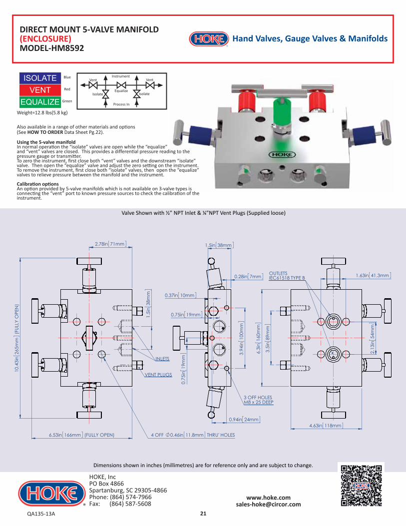
DIRECT MOUNT 5-VALVE MANIFOLD(ENCLOSURE)MODEL-HM8592
VENTEQUALIZE
Weight=12.8 lbs(5.8 kg)
ISOLATE Blue
Red
Green
Valve Shown with ½” NPT Inlet & ¼”NPT Vent Plugs (Supplied loose)
Dimensions shown in inches (millimetres) are for reference only and are subject to change.
Also available in a range of other materials and options (See HOW TO ORDER Data Sheet Pg.22).
VentInstrument
Process In
Vent
EqualizeIsolate Isolate
Using the 5-valve manifoldIn normal operation the “isolate” valves are open while the “equalize” and “vent” valves are closed. This provides a differential pressure reading to the pressure gauge or transmitter.To zero the instrument, first close both “vent” valves and the downstream “isolate” valve. Then open the “equalize” valve and adjust the zero setting on the instrument.To remove the instrument, first close both “isolate” valves, then open the “equalize” valves to relieve pressure between the manifold and the instrument.
Calibration optionsAn option provided by 5-valve manifolds which is not available on 3-valve types is connecting the “vent” port to known pressure sources to check the calibration of the instrument.
QA135-13A
HOKE, IncPO Box 4866 Spartanburg, SC 29305-4866Phone: (864) 574-7966 Fax: (864) 587-5608
22QA135-13A
HOKE, IncPO Box 4866 Spartanburg, SC 29305-4866Phone: (864) 574-7966 Fax: (864) 587-5608
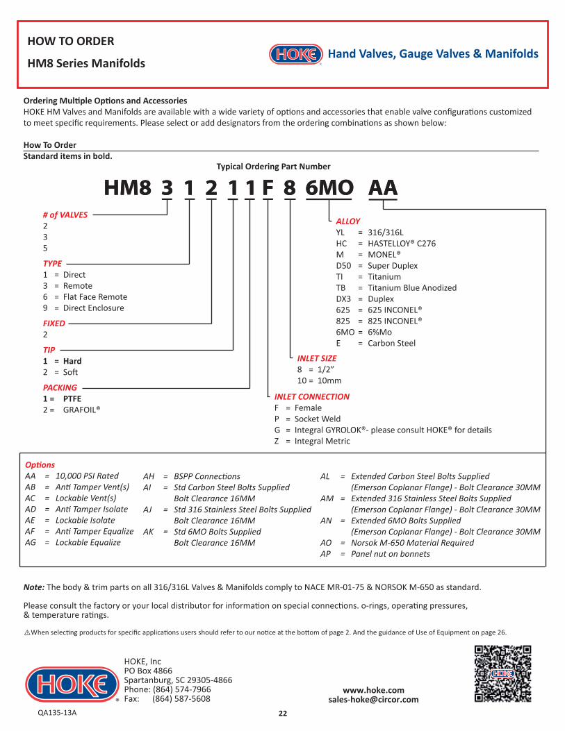
HM8 3 1 2 1 1 F 8 6MO AA HM8 3 1 2 1 1 F 8 6MO AA
Hand Valves, Gauge Valves & ManifoldsHOW TO ORDER
HM8 Series Manifolds
# of VALVES235
TYPE1 = Direct3 = Remote6 = Flat Face Remote9 = Direct Enclosure
FIXED2
TIP1 = Hard2 = Soft
PACKING1 = PTFE2 = GRAFOIL®
ALLOYYL = 316/316L HC = HASTELLOY® C276M = MONEL®D50 = Super DuplexTI = TitaniumTB = Titanium Blue AnodizedDX3 = Duplex625 = 625 INCONEL®825 = 825 INCONEL®6MO = 6%MoE = Carbon Steel
Note: The body & trim parts on all 316/316L Valves & Manifolds comply to NACE MR-01-75 & NORSOK M-650 as standard.
Please consult the factory or your local distributor for information on special connections. o-rings, operating pressures, & temperature ratings.
Typical Ordering Part Number
Ordering Multiple Options and AccessoriesHOKE HM Valves and Manifolds are available with a wide variety of options and accessories that enable valve configurations customized to meet specific requirements. Please select or add designators from the ordering combinations as shown below:
How To OrderStandard items in bold.
AL = Extended Carbon Steel Bolts Supplied (Emerson Coplanar Flange) - Bolt Clearance 30MMAM = Extended 316 Stainless Steel Bolts Supplied (Emerson Coplanar Flange) - Bolt Clearance 30MMAN = Extended 6MO Bolts Supplied (Emerson Coplanar Flange) - Bolt Clearance 30MMAO = Norsok M-650 Material RequiredAP = Panel nut on bonnets
AH = BSPP ConnectionsAI = Std Carbon Steel Bolts Supplied Bolt Clearance 16MMAJ = Std 316 Stainless Steel Bolts Supplied Bolt Clearance 16MMAK = Std 6MO Bolts Supplied Bolt Clearance 16MM
OptionsAA = 10,000 PSI RatedAB = Anti Tamper Vent(s)AC = Lockable Vent(s)AD = Anti Tamper IsolateAE = Lockable IsolateAF = Anti Tamper EqualizeAG = Lockable Equalize
⚠When selecting products for specific applications users should refer to our notice at the bottom of page 2. And the guidance of Use of Equipment on page 26.
INLET CONNECTIONF = FemaleP = Socket WeldG = Integral GYROLOK®- please consult HOKE® for detailsZ = Integral Metric
INLET SIZE8 = 1/2”10 = 10mm
Hand Valves, Gauge Valves & Manifolds
23
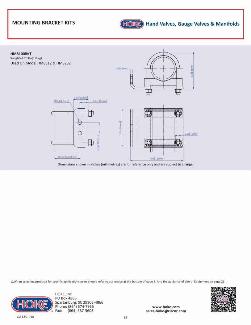
MOUNTING BRACKET KITS
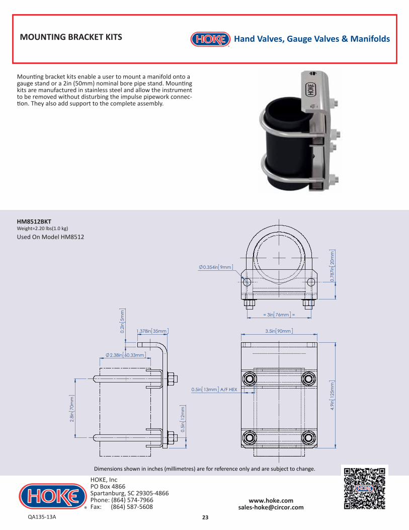
Dimensions shown in inches (millimetres) are for reference only and are subject to change.
Mounting bracket kits enable a user to mount a manifold onto a gauge stand or a 2in (50mm) nominal bore pipe stand. Mounting kits are manufactured in stainless steel and allow the instrument to be removed without disturbing the impulse pipework connec-tion. They also add support to the complete assembly.
QA135-13A
HOKE, IncPO Box 4866 Spartanburg, SC 29305-4866Phone: (864) 574-7966 Fax: (864) 587-5608
MOUNTING BRACKET KITS
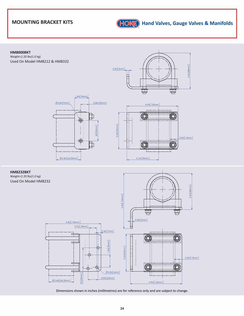
Dimensions shown in inches (millimetres) are for reference only and are subject to change.
HM8000BKTWeight=2.20 lbs(1.0 kg)
Used On Model HM8212 & HM8332
HM8232BKTWeight=2.20 lbs(1.0 kg)
Used On Model HM8232
Hand Valves, Gauge Valves & Manifolds
24
MOUNTING BRACKET KITS
Dimensions shown in inches (millimetres) are for reference only and are subject to change.
HM8100BKTWeight=2.20 lbs(1.0 kg)
Used On Model HM8312 & HM8232
Hand Valves, Gauge Valves & Manifolds
25QA135-13A
HOKE, IncPO Box 4866 Spartanburg, SC 29305-4866Phone: (864) 574-7966 Fax: (864) 587-5608
⚠When selecting products for specific applications users should refer to our notice at the bottom of page 2. And the guidance of Use of Equipment on page 26.
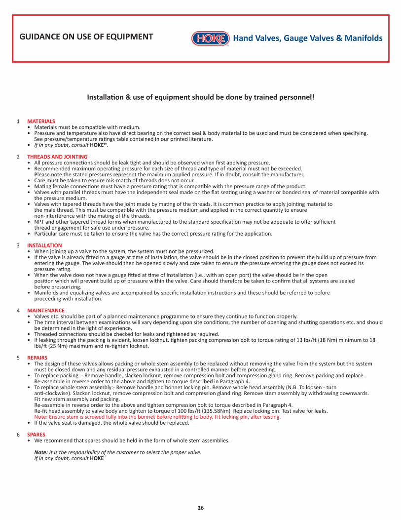
GUIDANCE ON USE OF EQUIPMENT
1 MATERIALS • Materials must be compatible with medium. • Pressure and temperature also have direct bearing on the correct seal & body material to be used and must be considered when specifying. See pressure/temperature ratings table contained in our printed literature. • If in any doubt, consult HOKE®.
2 THREADS AND JOINTING • All pressure connections should be leak tight and should be observed when first applying pressure. • Recommended maximum operating pressure for each size of thread and type of material must not be exceeded. Please note the stated pressures represent the maximum applied pressure. If in doubt, consult the manufacturer. • Care must be taken to ensure mis-match of threads does not occur. • Mating female connections must have a pressure rating that is compatible with the pressure range of the product. • Valves with parallel threads must have the independent seal made on the flat seating using a washer or bonded seal of material compatible with the pressure medium. • Valves with tapered threads have the joint made by mating of the threads. It is common practice to apply jointing material to the male thread. This must be compatible with the pressure medium and applied in the correct quantity to ensure non-interference with the mating of the threads. • NPT and other tapered thread forms when manufactured to the standard specification may not be adequate to offer sufficient thread engagement for safe use under pressure. • Particular care must be taken to ensure the valve has the correct pressure rating for the application.
3 INSTALLATION • When joining up a valve to the system, the system must not be pressurized. • If the valve is already fitted to a gauge at time of installation, the valve should be in the closed position to prevent the build up of pressure from entering the gauge. The valve should then be opened slowly and care taken to ensure the pressure entering the gauge does not exceed its pressure rating. • When the valve does not have a gauge fitted at time of installation (i.e., with an open port) the valve should be in the open position which will prevent build up of pressure within the valve. Care should therefore be taken to confirm that all systems are sealed before pressurizing. • Manifolds and equalizing valves are accompanied by specific installation instructions and these should be referred to before proceeding with installation.
4 MAINTENANCE • Valves etc. should be part of a planned maintenance programme to ensure they continue to function properly. • The time interval between examinations will vary depending upon site conditions, the number of opening and shutting operations etc. and should be determined in the light of experience. • Threaded connections should be checked for leaks and tightened as required. • If leaking through the packing is evident, loosen locknut, tighten packing compression bolt to torque rating of 13 lbs/ft (18 Nm) minimum to 18 lbs/ft (25 Nm) maximum and re-tighten locknut.
5 REPAIRS • The design of these valves allows packing or whole stem assembly to be replaced without removing the valve from the system but the system must be closed down and any residual pressure exhausted in a controlled manner before proceeding. • To replace packing: - Remove handle, slacken locknut, remove compression bolt and compression gland ring. Remove packing and replace. Re-assemble in reverse order to the above and tighten to torque described in Paragraph 4. • To replace whole stem assembly:- Remove handle and bonnet locking pin. Remove whole head assembly (N.B. To loosen - turn anti-clockwise). Slacken locknut, remove compression bolt and compression gland ring. Remove stem assembly by withdrawing downwards. Fit new stem assembly and packing. Re-assemble in reverse order to the above and tighten compression bolt to torque described in Paragraph 4. Re-fit head assembly to valve body and tighten to torque of 100 lbs/ft (135.58Nm) Replace locking pin. Test valve for leaks. Note: Ensure stem is screwed fully into the bonnet before refitting to body. Fit locking pin, after testing. • If the valve seat is damaged, the whole valve should be replaced.
6 SPARES • We recommend that spares should be held in the form of whole stem assemblies.
Note: It is the responsibility of the customer to select the proper valve. If in any doubt, consult HOKE®
Installation & use of equipment should be done by trained personnel!
Hand Valves, Gauge Valves & Manifolds
26
Han
d Va
lves
, Gau
ge V
alve
s, &
Man
ifold
s
Scan For
More Info
QA135-13A
HOKE, IncPO Box 4866 Spartanburg, SC 29305-4866Phone: (864) 574-7966 Fax: (864) 587-5608
79028ENG • 05/13 • APS3059