handbook - oregon state library: state employee information center
TRANSCRIPT

1
FLAMMABLE & COMBUSTIBLE LIQUID ABOVE GROUND TANK
FUEL DISPENSING
HANDBOOK
Nancy Orr State Fire Marshal
May 1996
Revised November 1998 Revised February 2002 Revised October 2004

2
Introduction This handbook was developed by the Codes & Technical Support Services Unit, Office of State Fire Marshal. The original product was reviewed by industry stakeholders and the fire service, and was created to provide a resource of requirements for the installation and use of above ground flammable and combustible liquid tanks for FUEL DISPENSING ONLY. The intent of this handbook is to provide a user friendly guide for fire service, the general public, and industry in applying code language in the State Of Oregon. We hope that you will find this handbook to be a useful resource guide to the installation and use of above ground flammable and combustible liquid tanks. Questions or requests for additional information can be directed to: Office of State Fire Marshal, Codes Unit, 4760 Portland Rd. N.E., Salem, OR 97305 - Ph. (503) 378-3473 - FAX (503) 373-1825

3
TABLE OF CONTENTS
STATE FIRE MARSHAL ABOVE GROUND TANK INSTALLATION GUIDELINE .................................................................................Section 1 STATE FIRE MARSHAL APPLICATION TO INSTALL ABOVE GROUND TANKS...................................................................................................Section 2 ABOVE GROUND TANK CHECKLIST..............................................................................Section 3 ABOVE GROUND TANK ILLUSTRATIONS.....................................................................Section 4
Section 1
Installation Guideline
4

5
ABOVE GROUND TANK REQUIREMENTS AT MOTOR VEHICLE FUEL DISPENSING STATIONS. The following table or guidelines have been developed to assist with application of the Oregon Fire Code for above ground tank installations.
TABLE 94-05 Type of Installation: (a) Tank Size Limitation: (c) Installation Specifications: (g) Use Condition 1:
Underground Tank(s). (Plan review done by D.E.Q.)
As specified in OFC Chapter 34, Section 3404.2.11.
As specified in OFC Chapter 34, Section 3404.2.11.
Use Condition 2: Above ground tank(s) inside a special enclosure inside a building.
Maximum shell size per individual tank limited to 6000 gallons, with an aggregate quantity of 18000 gallons. (f)
As specified in OFC Chapter 22, Section 2206.2.6.
Use Condition 3: Above ground tank(s) inside a special enclosure outside a building.
Maximum shell size per individual tank limited to 12000 gallons, with an aggregate quantity of 48000 gallons. (d) (f)
As specified in OFC Chapter 22, Section 2206.2.6.
Use Condition 4: (UL 2085) Above ground tank(s) which have at least a two-hour fire protection rated design.
Maximum shell size per individual tank limited to 12000 gallons, with an aggregate quantity of 48000 gallons. (d) (f)
As specified in OFC Chapter 22.
Use Condition 5: (UL 142) Above ground tank(s) outside of special enclosure(s) or building(s) and which have no fire protection rated design. (b)
Maximum shell size per individual tank limited to 6,000 gallons, with no restrictions on individual compartment size within each tank. (e) (f)
As specified in OFC Chapter 22.
NOTES: Refer to the table above. (Aggregate quantities are for the total of separate tanks, not the total for a compartmentalized tank). (a) Type of installations are the recommended methods in order of preference. It is the responsibility of the fire authority to
specify which condition is required for the specific jurisdiction. (b) When installations are proposed as specified in use condition 5, the applicant must provide written evidence when submitting
plans regarding the “practical difficulties” which are the basis for permitting use of this condition. (c) Tank size limitations are based on gasoline fuels and shall be specified per the table 94-05. When there is mixed use of
gasoline and diesel fuels, the maximum shell size shall be as per table 94-05. Tanks containing diesel fuels exclusively may be unlimited in size as approved by the Chief (OFC Section 2206.2.3(3), [Exception] ).
(d) Maximum aggregate quantity per installation limited to 48,000 gallons. (e) Maximum shell size limited to 6,000 gallons with an aggregate quantity of 18,000 gallons. (f) When an applicant plans for the installation of a single shell tank as specified in use condition 2, 3, 4,or 5 the following
requirements shall apply in addition to those specified in OFC Chapter 22 and 34. (i) Leak detection shall be installed to monitor both fuel and water intrusion into all interstitial spaces of the tank
including between bulkheads. The detection system shall initiate an audible or a distinctive visual signal at location approved by the fire marshal which will alert the person(s) responsible for the site.
NOTE: When a separate tank is installed for overflow protection, as in (f(iii)), leak detection shall also be installed inside the primary interior compartment of the overflow tank.
(ii) Tanks shall be designed with single or double bulkheads between fuel compartments. (iii) Tanks shall be provided with overflow protection to either a drainage or dike location or an approved secondary
containment location. The secondary containment location may be either a containment shell constructed as part of the primary fuel tank design or may be a separate tank adjacent to the primary tank.
NOTE: If a separate tank is installed, there shall be signs applied to the exterior of the tank which state, “FOR OVERFLOW PROTECTION ONLY-This tank NOT for continuous storage of fuel products”.
Notes to Table (continued) (iv) Tanks shall be either listed by an approved testing agency such as Underwriter’s Laboratories or shall be
constructed to meet the standards specified in UL 142 (Construction of Above Ground Flammable and Combustible Liquid Tanks). NOTE: Tanks installed under use condition 4 shall be UL2085 listed, labeled and meet the requirements specified in UL 2085. Tanks installed under condition use 5 that are not listed, shall have written documentation submitted with the plans regarding the design, construction, and manufacturer’s testing of the tank(s), including a stamp from a licensed engineer.

6
(v) All new tanks constructed after July 1, 1995, shall have a permanently affixed all-weather label attached to the
tank. The label shall be readily visible for inspection when the tank is installed for operation. The label shall include the following information:
Name and address of tank manufacturer Year tank was manufactured or date of recertification Capacity of tank in U.S. gallons Construction standards for tank; (UL label or 142/2085) (g) Tanks shall be located in relationship to property lines, public ways, and buildings on the same property as follows:
Use Condition 1: As specified in OFC Chapter 34, Section 3404.2.11.
Use Condition 2: As specified in the Building Code based on the occupancy classification.
Use Condition 3: Tanks up to 6,000 gallons shall be located five feet (5’) from the nearest side of a public way or building and fifteen feet (15’) from any property line. Tanks over 6,000 to 12,000 gallons shall be located fifteen feet (15’) from the nearest side of a public way or building and twenty-five feet (25’) from any property line. All distances are measured from the exterior of the special enclosure.
Use Condition 4: Tanks up to 6,000 gallons shall be located five feet (5’) from the nearest side of a public way or building and fifteen feet (15’) from any property line. Tanks over 6,000 to 12,000 gallons shall be located fifteen feet (15’) from the nearest side of a public way or building and twenty-five feet (25’) from any property line. All distances are measured from the exterior surface of the tank shell.
Use Condition 5: Tanks up to 6,000 gallons shall be located fifty feet (50’) from the nearest side of a public way or building and hundred feet (100’) from any property line, as measured from the exterior surface of the tank shell.
NOTE: If overflow protection is proposed to be through the use of an open drainage system or dike, the distances in use
condition 5 shall apply.

Section 2
Application
7

OFFICE OF STATE FIRE MARSHAL 4760 Portland Road NE, Salem OR 97305-1760
Phone: 503-373-1540 FAX: 503-373-1825
APPLICATION TO INSTALL FLAMMABLE / COMBUSTIBLE LIQUID ABOVE GROUND TANKS
Flammable/Combustible Liquids - To install tanks for the storage of flammable or combustible liquids above ground in excess of 1,000 gallons in either individual or aggregate quantities as specified in the Oregon Fire Code Section 3401.4.1.
Please make sure your application is complete and you submit two copies of the application and site plan. Incomplete applications will automatically be rejected. ALL INFORMATION MUST BE PROVIDED AND ALL NECESSARY SIGNATURES MUST BE OBTAINED
ο FLAMMABLE LIQUIDS: (Quantity) Use Condition
ο COMBUSTIBLE LIQUIDS: (Quantity) 1 2 3 4 or 5
NOTE: Flammable liquids have a flash point below 1000 F. Combustible liquids have a flash point at or above 1000 F. Retail (attended) Non-Retail (Cardlock) Bulk Plants & Refineries Farms or Construction Projects
Commercial, Industrial, Governmental or Manufacturing (fueling vehicles in connection with your business only) Other LOCATED ON PREMISES KNOWN AS: Phone #: SITE ADDRESS : Number Street City/Zip COUNTY___________________________________________________________________________________________________ NEAREST CROSS STREET/Road:
PLANNING/ZONING APPROVALS INSTALLER INFORMATION
8
PRINT name of Planning/Zoning Official
PRINT name of Company Installing Tank
Mailing Address of Planning/Zoning Official Mailing Address of Company Installing Tank City, State, Zip Code Telephone # City, State, Zip Code Telephone #
APPLICANT INFORMATION
SIGNATURE of Planning/Zoning Official Date
FIRE DEPARTMENT APPROVALS PRINT Fire Department Name Mailing Address of Fire Department City, State, Zip Code Telephone #
SIGNATURE of Fire Chief or Fire Marshal Date
PRINT name of Applicant Applying for Permit Mailing Address of Applicant City, State, Zip Code Telephone Number
SIGNATURE of Applicant Date NOTE: It is the responsibility of the applicant to ensure that this installation shall be in full compliance with applicable statutes of the state of Oregon and any local codes and ordinances. TWO SETS OF PLANS SHALL ACCOMPANY THIS APPLICATION which include a plot plan showing the location of any buildings, structures, tanks, piping and valves, tank capacities, diking, details of the design and construction, and fire protection. The plans shall also indicate the method of storage, quantities to be stored, distances from buildings and property lines, accessways, fire-protection facilities, and provisions for spill control, drainage control and secondary containment.

Section 3
Checklist
9

10
ABOVE GROUND TANK CHECKLIST Check your project against the provisions that apply to your use to meet current Oregon Fire Code requirements: GENERAL TANK PROVISIONS:
The design, fabrication and construction of tanks shall be in accordance with recognized good engineering practice and nationally recognized standards. (OFC 3404.3.2.2) The recognized standards for the State of Oregon is UL 2085 for 2-hour fire rated protected tanks and UL 142 for non 2-hour fire rated unprotected steel tanks. UL 142 tanks do not need to be UL labeled, but they must be designed, constructed and tested to the appropriate UL standard. Non-UL labeled tanks shall bear an all-weather label with the following information: name and address of tank manufacturer, year tank was manufactured or date of recertification, capacity of tank in U.S. gallons, and the tank construction standards (UL 142/2085).
Storage tanks are required to be located a minimum distance from property lines which may be built upon and a
minimum distance from the near side of any public way or nearest important building. (OFC 2206.2.3, OFC 3404.2.9.5). Refer to the illustration that provides distance requirements.
The minimum horizontal separation between an LP-gas container and a Class I, II or III-A liquid storage tank shall
be 20 feet (6096 mm). Suitable means shall be provided to prevent the accumulation of Class I, II or III-A liquids under adjacent LP-gas containers such as by dikes, diversion curbs or grading (OFC 3404.2.9.5.3).
Normal operating vents are required for tanks storing Class I, II, or III-A liquids to prevent development of
vacuum or pressure within storage tanks (OFC 3404.2.7.3). Such vents shall be sized in accordance with OFC 3404.2.7.3.4. Vents must terminate not less than 12 feet (3658 mm) above grade and 5 feet (1524 mm) from building openings or property lines of properties that can be built on and must discharge straight upward or outwards. (OFC 3404.2.7.3.3)
Each aboveground tank shall be equipped with adequate additional emergency venting that will relieve excessive
internal pressure caused by exposure to fires. (OFC 2206.6.2.5, 3404.2.7.4, 3404.2.9.6.2)
The area surrounding a tank or group of tanks shall be provided with drainage control or shall be diked to prevent accidental discharge of liquid from endangering adjacent tanks or adjoining property or reaching waterways. (OFC 2206.5, 3404.2.9.6.4, 3404.2.10)
All piping is required to be designed and fabricated from suitable materials having adequate strength and durability
to withstand the pressures, structural stresses and exposures to which they can be subjected. (OFC 3403.6)
All piping is required to be tested before being placed in service. Hydrostatic testing is required to be 150% of the
maximum anticipated pressure of the system, or pneumatic testing is required to be 110% of the maximum anticipated pressure of the system when operating, but not less than 5 psi. at the highest point of the system. (OFC 3403.6.3).
Electrical wiring and equipment shall be installed and maintained in accordance with the State Electrical Code and
as otherwise required by the Oregon Fire Code. (OFC 3403.1)
Both underground and above-ground piping shall be properly designed, installed and maintained, and protected from corrosion by either a cathodic protection system or by being constructed of corrosion-resistant materials. (OFC 3403.6.5)
PROVISIONS FOR MOTOR-VEHICLE FUEL DISPENSING STATIONS:
A portable fire extinguisher with a minimum rating of 2A:20-B:C shall be provided and located such that it is not more than 75 feet (22860 mm) from any pump, dispenser or fill-pipe opening. (OFC 2205.5)

11
Approved anti-siphon devices shall be installed in each external pipe connected to a tank when the piping extends
below the level of the top of the tank. (OFC 2206.6.2.4, 3404.2.9.6.10)
Tank openings shall be through the top only. (OFC 2206.6.2.1, 3404.2.9.6.9)
Guard posts or other approved barrier protection shall be provided for each tank and for connected piping subject to vehicle damage. (OFC 2206.4, 3404.2.8.6, 3404.2.9.6.5 ) When guard posts are used they shall be constructed of steel not less than 4 inches (102 mm) in diameter and concrete filled, and spaced not more than 4 feet (1219 mm) between posts on center, and set not less than 3 feet (914 mm) deep in a concrete footing that is not less than a 15-inch (381 mm) diameter, and set with the top of the post not less than 3 feet (914 mm) above the ground, and located not less than 3 feet (914 mm) from the tank. (OFC 312.2)
Warning signs and identification signs shall be installed to clearly identify hazards. Conspicuous signs shall be
posted prohibiting smoking, prohibiting dispensing into unapproved containers, requiring vehicle engines to be stopped during fueling and prohibit portable containers being filled while located inside the trunk, passenger compartment, or truck bed of a vehicle. (OFC 2205.6 & 3403.5)
Two-hour fire rated protected tanks at motor vehicle fuel-dispensing stations containing flammable or combustible
liquids shall not exceed a 12,000 gallon (45 425 L) individual or 48,000 gallon (181 700 L) aggregate capacity. (OFC 2206.2.3) Unprotected tanks containing flammable liquids (gasoline) at motor vehicle fuel-dispensing stations shall not exceed a 6,000 gallon (22 712 L) individual or 18,000 gallon (68 137 L) aggregate capacity. Unprotected compartmentalized tanks shall not exceed 6,000 gallons, with no restriction on individual compartment size. Tanks containing combustible liquids (diesel) shall be as per OFC 2206.2.3(3), Exception.
Aboveground tanks shall be provided with an independent means of notifying the person filling the tank that the
fluid level has reached 90% by providing an audible or visual alarm signal and a positive shutoff that stops the flow of fuel to the tank when the quantity of liquid in the tank reaches 95%. (OFC 2206.6.2.3, 3404.2.7.5.8, 3404.2.9.6.6)
Dispensing devices at motor vehicle fuel-dispensing stations shall be located 10 feet (3048 mm) or more from
property lines, and 10 feet (3048 mm) or more from buildings having a combustible exterior, and such that all portions of the vehicle being fueled will be on the premises. The nozzle, when the hose is fully extended, shall not reach within 5 feet (1524 mm) of building openings, and 20 feet (6096 mm) or more from fixed sources of ignition. (OFC 2203.1)
An approved emergency shutoff valve designed to close automatically in the event of impact or fire exposure shall
be properly installed in the dispensing supply line at the base of each dispensing device. (OFC 2206.7.4)
Product delivery hose for Class I and II liquids shall be equipped with a listed emergency breakaway device designed to retain liquid on both sides of the breakaway point. Such devices shall be installed and maintained in accordance with manufacturer’s instructions. (OFC 2206.7.5.1)
A listed automatic-closing type hose nozzle valve shall be provided on dispensers used for dispensing Class I, II or III-A liquids. (OFC 2206.7.6)
Dispensing devices shall be protected against physical damage from vehicles by mounting on a concrete island 6
inches (152 mm) or more in height or by other approved methods. (OFC 2206.7.3)
Emergency shutdown devices shall be provided for all fuel dispensers and shall be located within 100 feet (30 480 mm) of, but not less than 20 feet (6096 mm) from, dispensers. (OFC 2203.2, 2204.3.3)

PROVISIONS FOR UNSUPERVISED DISPENSING OPERATIONS:
The owner of a non-retail facility which dispenses Class I liquids shall hold a valid nonretail facility license issued by the State Fire Marshal under OAR Chapter 837, Division 20. EXCEPTION: Class II and III-A liquids and fleet operations.
At locations where unsupervised dispensing will occur, conspicuously posted instructions for the safe operation of
dispensing equipment, and posted telephone numbers for the owner or operators are required. (OFC 2204.3.4)
At locations where unsupervised dispensing will occur, a sign, in addition to other required signs, shall be posted in a conspicuous location reading: (OFC 2204.3.5)
IN CASE OF FIRE, SPILL OR RELEASE 1. Use emergency pump shutoff! 2. Report the accident!
Fire Department Telephone No. 911 . Facility Address .
Dispensing equipment at unsupervised locations shall comply with one of the following: (OFC 2204.3.7)
1. The amount of fuel being dispensed is limited in quantity by a preprogrammed card as approved. 2. Dispensing devices shall be programmed or set to limit uninterrupted fuel delivery to 40 gallons (152 L)
and require a manual action to resume continued delivery. Exception: Class II or IIIA liquids may be programmed or set to limit uninterrupted fuel delivery of up to 250
gallons (950 L).
Each non-retail facility shall be adequately lighted at all times when available for use. OAR 837-020-0040(2)(e).
Where retail and non-retail dispensing of Class I Flammable Liquids occurs during the same hours, non-retail pump islands shall be separated from retail pump islands by a space of at least 50 feet (15 240 mm). Unless separated by at least 50 feet (152 40 mm), retail and non-retail dispensing shall not occur during the same hours at a facility. ( OAR 837-020-0040[4][b]) Also see EXCEPTION.
During hours of operation, stations having unsupervised dispensing shall be provided with a fire alarm transmitting
device. A telephone not requiring a coin to operate is acceptable. (OFC 2204.3.6 & OAR 837-020-0040[f])
NOTE: Compliance with the Oregon Fire Code does not automatically constitute compliance with EPA or other federally mandated rules, and further research may be necessary. It is the responsibility of the applicant to ensure that all installations are in full compliance with applicable statutes of the state of Oregon and any local codes and ordinances.
12
Section 4
Illustrations
13

Underground Tanks at Motor Vehicle Fuel-Dispensing Stations.
USE CONDITION 1 1. Underground Tanks have no size restrictions. 2. The distance from any part of the tank to nearest wall of
basement, pit, cellar or lot line shall not be less than 3 feet (914 mm). (OFC 3404.2.11.2)
3. A minimum distance of 1 foot (305 mm), shell to shell
shall be maintained between underground tanks. (OFC 3404.2.11.2)
4. Tanks shall be set on firm foundations and surrounded
by at least 6 inches (152 mm) of noncorrosive inert material, such as clean sand or gravel. (OFC 3404.2.11.3)
5. Tanks shall be covered with a minimum of 2 feet (0.6 m)
of earth or shall be covered by not less than 1 foot (0.3 m) of earth, on top of which shall be placed a slab of reinforced concrete not less than 4 inches (10 cm) thick. (NFPA 30, Section 2.4.2.2)
9
Building
Basement
7
Submersible, Top Suction pump, with Anti-Siphon valve. (OFC 2206.6.2.4).
Emergency Shutoff impact valve required. (OFC
1
2
4
5 8
This figure for illustrative purposes only; text shall govern
6. Where tanks that could become buoyant due to a rise in
the level of the water table or due to location in an area subject to flooding, uplift protection shall be provided. (OFC 3404.2.7.8)
7. Normal venting is required and shall terminate at a point
not less than 12 feet (3658 mm) above the adjacent ground level. They shall discharge upward or horizontally and not within 5 feet (1524 mm) of buildings or lot lines of properties that can be built on. (OFC 3404.2.7.3.3)
8. Fill pipes shall be equipped with an overflow prevention
system. (OFC 3404.2.11.4) 9. Underground tanks and piping shall be protected from
corrosion by a cathodic protection system or by the use of corrosive resistant materials.
(OFC 3404.2.7.9) 10. Before being covered or placed into use, tanks and
piping shall be tested. (OFC 3404.2.12)
14

15
1. Tanks shall be designed, fabricated and constructed in accordance with OFC 3404.2.7. Tanks containing Class I, II or III-A liquids shall be limited in size to a maximum of 6000 gallons (12 710 L) individual or 18000 gallons (68 130 L) aggregate
capacity per installation. (OFC 2206.2.6) 2. Enclosure shall be liquid tight and vapor tight and at least six inch (152 mm) thick reinforced concrete sides, top and bottom. Openings shall be in the top of the enclosure only. (OFC 2206.2.6) 3. Each fill connection shall be provided with a spill container having a capacity of not less than 5 gallons (19 L). Spill containers shall be noncombustible and equipped with a drain that returns the fuel into the tank. (OFC 2206.6.2.6) Fill connections
shall be equipped with a 90% overflow prevention system. (OFC 3404.2.9.6.6) 4. Emergency venting equal to the venting capacity of the tank emergency vent. (OFC 2206.6.2.5) 5. Normal venting is required and shall not be less than 1 1/4” (32 mm) I.D. (OFC 3404.2.7.3) and must terminate at a point not less than 12 feet (3658 mm) above grade. (OFC 3404.2.7.3.3). 6. Emergency venting shall be provided that will relieve excessive internal pressure caused by exposure to fire (OFC 2206.6.2.5) and must vent outside the enclosure 12 feet (3658 mm) above grade or if venting inside the enclosure, the enclosure must
have emergency relief venting equal to the venting capacity of the tank vent. (OFC 3404.2.7.3.3) 7. An approved pump shall be provided that will suction fuel through the top of the tank only. (OFC 2206.7.2) Anti-Siphon devices are required on each external pipe connected to the tank when the pipe extends below the level of the top of the tank.
(OFC 2206.6.2.4) 8. Dispensing devices shall be mounted on a concrete island 6 inches (152 mm) or more in height and shall be secured in an approved manner. (OFC 2206.7.3). Dispensers shall be equipped with a listed automatic-closing-type hose nozzle valve.
(OFC 2206.7.6) 9. An approved emergency shutoff impact valve shall be rigidly mounted and connected by a union in the dispensing supply line at the base of each dispensing device. (OFC 2206.7.4) 10. Diked areas for secondary containment shall be designed of a capacity to retain the fuel from the largest tank plus the displaced volume (approx. 110% of the largest tank). (OFC 2206.5) Vapor detection is required inside the enclosure which
enunciates a visual signal at a normally occupied location on-site. (OFC 2704.2.2.5) A clear space of not less than 3 feet (910 mm) shall be provided for maintenance and inspection. (OFC 2206.2.6) 11. Tank supports shall be provided according to OFC 3404.2.9.2. 12. Stairways, platforms and walkways shall be provided according to OFC 3404.2.9.3. 13. Warning signs and identification signs shall be installed to clearly identify the hazards. (OFC 3403.5 & 3404.2.3) 14. Piping systems shall be substantially supported and protected against physical damage and excessive stresses arising from settlement, vibration, expansion, contraction, or exposure to fire and shall be liquid and vapor tight. (OFC 3403.6.8) 15. All electrical wiring shall be classified as specified in OFC Table 3403.1.1.
Aboveground Tanks at Motor-Vehicle Fuel Dispensing Stations,
Inside of Special Enclosure, Inside of Buildings.
DANGER FLAMMABLE LIQUID
1
6
5
3
7
12
138
9
14
10
11
This figure for illustrative purposes only; text shall govern
Permanently affixed all-weather label with the following: ∗ Name and address of tank manufacturer. ∗ Year tank was manufactured or date of recertification. ∗ Capacity of tank in U.S. gallons. ∗ Construction standards for tank; (UL label or 142/2085)
2
USE CONDITION 2
4
15
32 1

16
1. Tanks shall be designed, fabricated and constructed in accordance with OFC 3404.2.7. Tanks containing Class I, II or III-A liquids shall be limited in size to a maximum of 12000 gallons (45 420 L) individual or 48000 gallons (181 680 L) aggregate
capacity per installation. (OFC 2206.2.3) 2. Enclosure shall be liquid tight and vapor tight and at least six inch (152 mm) thick reinforced concrete sides, top and bottom. Openings shall be in the top of the enclosure only. (OFC 2206.2.6) 3. Each fill connection shall be provided with a spill container having a capacity of not less than 5 gallons (19 L). Spill containers shall be noncombustible and equipped with a drain that returns the fuel into the tank. (OFC 2606.6.2.6) Fill connections
shall be equipped with a 90% overflow prevention system. (OFC 3404.2.9.6.6) 4. Emergency venting equal to the venting capacity of the tank emergency vent. (OFC 2206.6.2.5) 5. Normal venting is required and shall not be less than 1 1/4” I.D (32 mm) (OFC 3404.2.7.3) and must terminate at a point not less than 12’ feet (3658 mm) above grade. (OFC 3404.2.7.3.3). 6. Emergency venting shall be provided that will relieve excessive internal pressure caused by exposure to fire (OFC 2206.6.2.5) and must vent outside the enclosure 12 feet (3658 mm) above grade or if venting inside the enclosure, the enclosure must
have emergency relief venting equal to the venting capacity of the tank vent. (OFC 3404.2.7.3.3) 7. An approved pump shall be provided that will suction fuel through the top of the tank only. (OFC 2206.7.2). Anti-Siphon devices are required on each external pipe connected to the tank when the pipe extends below the level of the top of the tank.
(OFC 2206.6.2.4). 8. Dispensing devices shall be mounted on a concrete island 6 inches (152 mm) or more in height and shall be secured in an approved manner. (OFC 2206.7.3) Dispensers shall be equipped with a listed automatic-closing-type hose nozzle valve. (OFC
2206.7.6). 9. An approved emergency shutoff impact valve shall be rigidly mounted and connected by a union in the dispensing supply line at the base of each dispensing device. (OFC 2206.7.4). 10. Diked areas for secondary containment shall be designed of a capacity to retain the fuel from the largest tank plus the displaced volume (approx. 110% of the largest tank). (OFC 2206.5) Vapor detection is required inside the enclosure which
enunciates a visual signal at a normally occupied location on-site. (OFC 2204.2.2.5). A clear space of not less than 3 feet (910 mm) shall be provided for maintenance and inspection. (OFC 2206.2.6). 11. Tank supports shall be provided according to OFC 3404.2.9.2. 12. Stairways, platforms and walkways shall be provided according to OFC 3404.2.9.3. 13. Warning signs and identification signs shall be installed to clearly identify the hazards. (OFC 3403.5 & 3404.2.3). 14. Piping systems shall be substantially supported and protected against physical damage and excessive stresses arising from settlement, vibration, expansion, contraction, or exposure to fire and shall be liquid and vapor tight. (OFC 3404.6.8). 15. All electrical wiring shall be classified as specified in OFC Table 3403.1.1.
Aboveground Tanks at Motor-Vehicle Fuel Dispensing Stations,
Inside of Special Enclosure, Outside of Buildings.
DANGER FLAMMABLE LIQUID
1
6
5
3
7
12
138
9
11
USE CONDITION 3 This figure for illustrative purposes only; text shall govern
4
14
10Permanently affixed all-weather label with the following: ∗ Name and address of tank manufacturer. ∗ Year tank was manufactured or date of recertification. ∗ Capacity of tank in U.S. gallons. ∗ Construction standards for tank; (UL label or 142/2085)
2
15
32 1
+
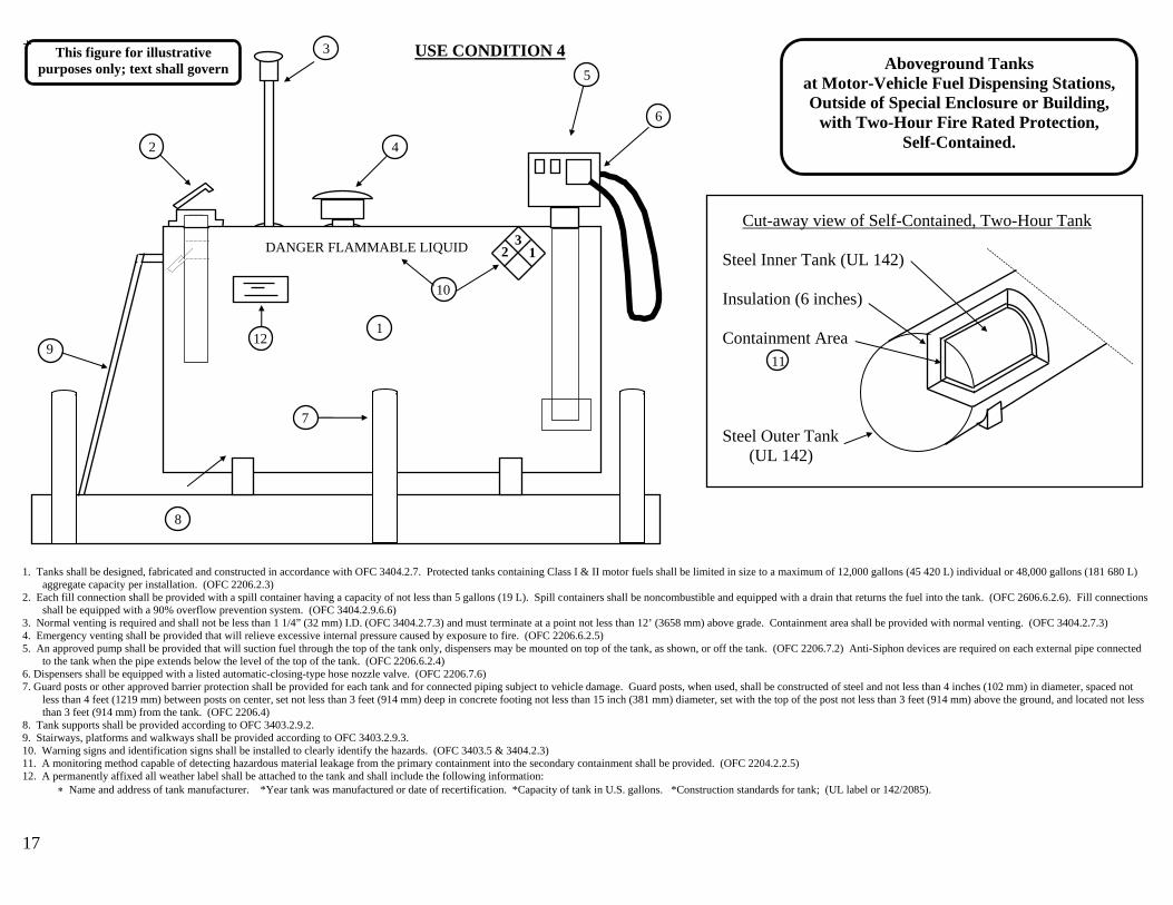
Cut-away view of Self-Contained, Two-Hour Tank
Steel Inner Tank (UL 142)
Insulation (6 inches)
Containment Area
Steel Outer Tank (UL 142)
Aboveground Tanks at Motor-Vehicle Fuel Dispensing Stations, Outside of Special Enclosure or Building,
with Two-Hour Fire Rated Protection, Self-Contained.
8
DANGER FLAMMABLE LIQUID
1
3
42
5
9
10
6
7
USE CONDITION 4
32 1
12
This figure for illustrative purposes only; text shall govern
11
1. Tanks shall be designed, fabricated and constructed in accordance with OFC 3404.2.7. Protected tanks containing Class I & II motor fuels shall be limited in size to a maximum of 12,000 gallons (45 420 L) individual or 48,000 gallons (181 680 L)
aggregate capacity per installation. (OFC 2206.2.3) 2. Each fill connection shall be provided with a spill container having a capacity of not less than 5 gallons (19 L). Spill containers shall be noncombustible and equipped with a drain that returns the fuel into the tank. (OFC 2606.6.2.6). Fill connections
shall be equipped with a 90% overflow prevention system. (OFC 3404.2.9.6.6) 3. Normal venting is required and shall not be less than 1 1/4” (32 mm) I.D. (OFC 3404.2.7.3) and must terminate at a point not less than 12’ (3658 mm) above grade. Containment area shall be provided with normal venting. (OFC 3404.2.7.3) 4. Emergency venting shall be provided that will relieve excessive internal pressure caused by exposure to fire. (OFC 2206.6.2.5) 5. An approved pump shall be provided that will suction fuel through the top of the tank only, dispensers may be mounted on top of the tank, as shown, or off the tank. (OFC 2206.7.2) Anti-Siphon devices are required on each external pipe connected
to the tank when the pipe extends below the level of the top of the tank. (OFC 2206.6.2.4) 6. Dispensers shall be equipped with a listed automatic-closing-type hose nozzle valve. (OFC 2206.7.6) 7. Guard posts or other approved barrier protection shall be provided for each tank and for connected piping subject to vehicle damage. Guard posts, when used, shall be constructed of steel and not less than 4 inches (102 mm) in diameter, spaced not
less than 4 feet (1219 mm) between posts on center, set not less than 3 feet (914 mm) deep in concrete footing not less than 15 inch (381 mm) diameter, set with the top of the post not less than 3 feet (914 mm) above the ground, and located not less than 3 feet (914 mm) from the tank. (OFC 2206.4)
8. Tank supports shall be provided according to OFC 3403.2.9.2. 9. Stairways, platforms and walkways shall be provided according to OFC 3403.2.9.3. 10. Warning signs and identification signs shall be installed to clearly identify the hazards. (OFC 3403.5 & 3404.2.3) 11. A monitoring method capable of detecting hazardous material leakage from the primary containment into the secondary containment shall be provided. (OFC 2204.2.2.5) 12. A permanently affixed all weather label shall be attached to the tank and shall include the following information:
∗ Name and address of tank manufacturer. *Year tank was manufactured or date of recertification. *Capacity of tank in U.S. gallons. *Construction standards for tank; (UL label or 142/2085).
17

18
3
4
5
12
9
DANGER FLAMMABLE LIQUID 6
1
7
8 10 13
123
11
USE CONDITION 5 This figure for illustrative purposes only; text shall govern
Aboveground Tanks at Motor-Vehicle Fuel Dispensing Stations, Outside of Special Enclosure or Building,
No Two Hour Fire Rated Protection, Diked Secondary Containment.
2 1. Tanks shall be designed, fabricated and constructed in accordance with OFC 3404.2.7. Unprotected tanks containing Class I motor fuels shall be limited in shell size to a maximum of 6,000 gallon (22 712 L) individual or 18,000 gallon (68 137 L)
aggregate capacity per installation. (OFC 2206.2.3) See Exception for larger quantities of Class II or III- A liquids. 2. Each fill connection shall be provided with a spill container having a capacity of not less than 5 gallons (19 L). Spill containers shall be noncombustible and equipped with a drain that returns the fuel into the tank. (OFC 2206.6.2.6). Fill connections
shall be equipped with a 90% overflow prevention system. (OFC 3404.2.7.5.8) 3. Normal venting is required and shall not be less than 1 1/4” (32 mm) I.D (OFC 3404.2.7.3) and must terminate at a point not less than 12’ (3658 mm) above grade. (OFC 3404.2.7.3.3) 4. Emergency venting shall be provided that will relieve excessive internal pressure caused by exposure to fire. (OFC 2206.6.2.5) 5. An approved pump shall be provided that will suction fuel through the top of the tank only. (OFC 2206.7.2) Anti-Siphon devices are required on each external pipe connected to the tank when the pipe extends below the level of the top of the tank.
(OFC 2206.6.2.4) 6. Dispensing devices shall be mounted on top of the tank or off tank, as shown, on a concrete island 6” (152 mm) or more in height and shall be secured in an approved manner. (OFC 2206.7.3) Dispensers shall be equipped with a listed automatic-
closing-type hose nozzle valve. (OFC 2206.7.6) 7. An approved emergency shutoff impact valve shall be rigidly mounted and connected by a union in the dispensing supply line at the base of each dispensing device. (OFC 2206.7.4) 8. Diked areas for secondary containment shall be constructed of earth, steel, concrete or solid masonry designed to be liquid tight and of a capacity to retain the fuel from the largest tank plus the displaced volume (approx. 110% of the largest tank).
(OFC 2206.5) 9. Tank supports shall be provided according to OFC 3404.2.9.2. 10. Stairways, platforms and walkways shall be provided according to OFC 3404.2.9.3. 11. Warning signs and identification signs shall be installed to clearly identify the hazards. (OFC 3403.5 &3404.2.3) 12. Piping systems shall be substantially supported and protected against physical damage and excessive stresses arising from settlement, vibration, expansion or contraction, or exposure to fire. (OFC 3404.6.8) 13. A permanently affixed all weather label shall be attached to the tank and shall include the following information:
∗ Name and address of tank manufacturer. *Year tank was manufactured or date of recertification. *Capacity of tank in U.S. gallons. *Construction standards for tank (UL label or 142/2085).

19
Aboveground Bulkheaded Tanks at Motor-Vehicle Fuel Dispensing Station, Outside of Special Enclosure or Building,
No Two Hour Fire Rated Protection, Diked Secondary Containment.
3
DANGER FLAMMABLE LIQUID
7
8
2
45
10
123
6
11
4
12
1
6
9
This figure for illustrative purposes only; text shall govern
USE CONDITION 5
5
1. Tanks shall be designed, fabricated and constructed in accordance with OFC 3404.2.7. Unprotected bulkheaded tanks, containing Class I motor fuels, shall be limited to a maximum shell size of 6,000 gallons (22 712 L) and 18,000gallon (68 137 L)
aggregate capacity per installation. (OFC 2206.2.3) See Exception for larger quantities of Class II or III-A liquids. 2. Each fill connection shall be provided with a spill container having a capacity of not less than 5 gallons (19 L). Spill containers shall be noncombustible and equipped with a drain that returns the fuel into the tank. (OFC 2206.6.2.6). Fill connections
shall be equipped with a 90% overflow prevention system. (OFC 3404.2.7.5.8) 3. Normal venting is required in each compartment and shall not be less than 1 1/4” (32 mm) I.D. (OFC 3404.2.7.3) and must terminate at a point not less than 12’ (3658 mm) above grade. (OFC 3404.2.7.3.3) 4. Emergency venting shall be provided in each compartment that will relieve excessive internal pressure caused by exposure to fire. (OFC 2206.6.2.5) 5. Approved pumps shall be provided that will suction fuel through the top of the tank only. (OFC 2206.7.2) Anti-Siphon devices are required on each external pipe connected to the tank when the pipe extends below the level of the top of the tank.
(OFC 2206.6.2.4) 6. Dispensing devices shall be mounted on top of the tank, as shown, or off tank on a concrete island 6” (152 mm) or more in height and shall be secured in an approved manner. (OFC 2206.7.3) Dispensers shall be equipped with a listed automatic-
closing-type hose nozzle valve. (OFC 2206.7.6) 7. Diked areas for secondary containment shall be constructed of earth, steel, concrete or solid masonry designed to be liquid tight and of a capacity to retain the fuel from the largest tank plus the displaced volume (approx. 110% of the largest tank).
(OFC 2206.5) 8. Tank supports shall be provided according to OFC 3404.2.9.2. 9. Stairways, platforms and walkways shall be provided according to OFC 3404.2.9.3. 10. Warning signs and identification signs shall be installed to clearly identify the hazards. (OFC 3403.5 & 3404.2.3) 11. Tanks shall be designed with single or double bulkheads between fuel compartments, interstitial spaces shall be provided with leak detection. 12. A permanently affixed all weather label shall be attached to the tank and shall include the following information:
∗ Name and address of tank manufacturer. *Year tank was manufactured or date of recertification. *Capacity of tank in U.S. gallons. *Construction standards for tank; (UL label or 142/2085).

USE CONDITION 5 (Supplemental Info)
Aboveground Tanks This figure for illustrative purposes only; text shall govern at Motor-Vehicle Fuel Dispensing Stations, Normal Venting Reqd.;
OFC 3404.2.7.3 Outside of Special Enclosure or Building, No Two Hour Fire Rated Protection,
Diked Secondary Containment. Spill Control Reqd.; OFC
2206.6.2.6 Emergency Venting Reqd.; OFC 2206.6.2.5
20
DANGER FLAMMABLE LIQUID
* Either fill pipe configuration is acceptable.
Spill Control Reqd.; OFC 2206.6.2.6
Manual Control Valve Reqd.; OFC 3403.6.6.2
Backflow Prevention Reqd.; OFC 3403.6.6.1
90% Shutoff Reqd.; OFC 3404.2.7.5.8
Tight Fill Connection Reqd.; OFC 2206.6.2.2
32 1
90% Shutoff Reqd.; OFC 3404.2.7.5.8
Top Suction Pump Reqd.; OFC 2206.7.2
Listed, Automatic-closing Nozzle Reqd.; OFC 2206.7.6
Ladder Reqd.; OFC 3404.2.9.3 Warning Signs Reqd.; OFC
3403.5 & 3404.2.3
Secondary Containment Reqd.;
OFC 2206.5
All-Weather Label Reqd. Piping Support Reqd.; OFC 3403.6.8
Tank Constructed to UL 142
Tank Supports Reqd.; OFC 3404.2.9.2
Fuel
Water
Water
Fuel
Examples of Fuel/Oil Separator

21
• • • Tanks shall be of single-compartment design, constructed in accordance with OFC 3404.2.7. Tanks containing Class I or II motor fuels may be unprotected and shall be limited to a maximum of 1,100 gallons (4164 L) for permanent
installations or a maximum of 10,000 gallons (37 854 L) for temporary installations. (OFC 3406.2.4) • Each fill connection shall be provided with a spill container having a capacity of not less than 5 gallons (19 L). Spill containers shall be noncombustible and equipped with a drain that returns the fuel into the tank. (OFC 2206.6.2.6) Fill
connections shall be equipped with a 90% overflow prevention system. (OFC 3404.2.7.5.8) Fill openings shall be equipped with a locking closure device and shall be separate from vent openings. (OFC 3406.2.4.1) • Each tank shall be provided with a free-opening vent to relieve vacuum or pressure which could develop in normal operation or from fire exposure. (OFC 3406.2.9.2) Vents must terminate at a point not less than 12’ (3658 mm) above grade.
(OFC 3404.2.7.3.3) • Storage tanks shall be kept free of weeds and extraneous combustible material. Open flames and smoking are prohibited in flammable or combustible storage areas. (OFC 3406.2.1) • Tanks with top openings only shall be mounted as follows: • On well-constructed legs connected to shoes or runners designed so that the tank is stabilized and the entire tank and its supports can be moved as a unit, or • For stationary tanks, on a stable base of timbers or blocks approximately 6 inches (152 mm) in height which prevents the tank from contacting the ground. (OFC 3406.2.5.1) • Tanks with top openings shall be equipped with a tightly and permanently attached, approved pumping device having an approved hose of sufficient length for filling vehicles, equipment or containers to be served from the tank. Either the
pump of the hose shall be equipped with a padlock to its hanger to prevent tampering. An effective antisiphoning device shall be included in the pump discharge unless a self-closing nozzle is provided. Siphons or internal pressure discharge devices shall not be used. (OFC 3406.2.5.1.1 )
• Tanks with a connection in the bottom or the end for gravity dispensing liquids shall be mounted as follows: • Supports to elevate the tank for gravity discharge shall be of adequate strength and designed to provide stability, and • Bottom or end openings for gravity discharge shall be equipped with a valve located adjacent to the tank shell which will close automatically in the event of fire through the operation of an effective heat-actuated releasing device. If this valve
cannot be operated manually, it shall be supplemented by a second manually operated valve. The gravity discharge outlet shall be provided with an approved hose equipped with a self-closing valve at the discharge end of a type that can be padlocked to its hanger. (OFC 3406.2.5.2)
• Diked areas for secondary containment shall be constructed of earth, steel, concrete or solid masonry designed to be liquid tight and of a capacity to retain the fuel from the largest tank plus the displaced volume (approx. 110% of the largest tank). (OFC 2206.5). Containment can also be accomplished through the use of a self-contained tank in lieu of the diked area.
Aboveground Tanks at Farms and Construction Sites,
Outside of Special Enclosure or Building, No Two Hour Fire Rated Protection,
Diked Secondary Containment.
This figure for illustrative purposes only; text shall govern
Tank Supports
GASOLINE FLAMMABLE-KEEP FIRE AND FLAME AWAY
KEEP 50 FEET FROM BUILDINGS
Permanently affixed all weather label with the following information: ∗ Name and address of tank manufacturer. ∗ Year tank was manufactured or date of recertification. ∗ Capacity of tank in U.S. gallons. ∗ Construction standards for tank; (UL 142).
* Stairways, platforms and walkways shall be noncombustible and shall be designed and constructed in accordance with the Building Code (OFC 3404.2.9.3).
* Tanks shall be conspicuously marked (OFC 3406.2.2).
* Tanks shall be kept outside of and at least 50 ft (15 240 mm) from buildings and combustible storage. All containers, vehicles and equipment shall be at least 50 ft (15 240 mm) from structures, haystacks or other combustible storage when being filled (OFC 3406.2.4.3).
* A portable fire extinguisher with a minimum rating of 20-B: C shall be provided within 75 feet of the tank(OFC 3406.2.7).
Normal Venting
Emergency Venting
Suction Pump (Tanks can be gravity discharge)
Fill Opening
Ladder
Diked Area

22
Minimum Separation For Unprotected Tanks UL 142 Table 2206.2.3 - Minimum Separation Requirements For Above-Ground Tanks (other tanks)
Individual Tank Capacity (gallons)
Minimum distance from property line which can be built upon, including the
opposite side of a public way (ft)
Minimum distance from the nearest side of any public way or from the nearest important
building on the same property (ft)
Minimum distance between
tanks (ft) Less than or equal to 6,000
15 5 3
Greater than 6,000 25 15 3
NOTE: A. Distance requirements for tanks installed inside special enclosures, outside of buildings, shall be equal to protected tanks. B. Distance requirements for tanks installed inside special enclosures, inside buildings, shall be as specified in the building code based on the occupancy classification.
1. Dispensing devices shall be equipped with an approved emergency shutoff impact valve, a listed automatic nozzle, and shall be protected against physical damage. 2. Nozzles, when fully extended, shall not reach within 5 ft of building openings or within 20 ft of fixed sources of ignition. 3. Dispensing devices shall be located 10 ft or more from property lines, and 10 ft or more from buildings have a combustible exterior. 4. Emergency shutoff devices shall be provided for all fuel dispensers and shall be located within 100 ft of, but not less than 20 ft from, dispensers. 5. A portable fire extinguisher with a minimum rating of 2A:20BC shall be provided within 75 ft of any pump. 6. Signs prohibiting smoking, prohibiting dispensing into unapproved containers and requiring vehicle engines to be stopped during refueling shall be conspicuously posted within sight of each dispenser.
Aboveground Tanks at Motor-Vehicle Fuel Dispensing Stations -
Distance Requirements.
Building
100 ft - For multiple installations on the same property
See table (property line) Tank Constructed to UL
142 or UL 2085 See table (public way)
See table (Important building)
Diked area shall hold the capacity of the largest tank + the displaced volume
(approx. 110%). Double-wall tanks do not require a diked containment area.
6
2
33
4
51
Individual Tank Minimum Distance Minimum distance from Capacity to Property line or nearest side of public (gallons) opposite side of public way or nearest way (ft) building (ft) 6000 100 50