harmonic filters design for iec 61000 compliance · design for iec 61000 compliance ... ¾as/nzs...
TRANSCRIPT
1
GRID
Marius JansenFebruary 2011
HARMONIC FILTERSDesign for IEC 61000 compliance
24/2/2011 / MJ - P 2
Overview
What is a filter
Types of harmonic filters
What is harmonic compliance
Designing for compliance
Designing for reliability
Other considerations

2
24/2/2011 / MJ - P 3
Filter defined
Device or combination of devices
Intended to reduce harmonic voltage distortion
Caused by non-linear loads in the network
That may be otherwise result in costs, losses or damage to other equipment in the network
24/2/2011 / MJ - P 4
Filter defined
Device or combination of devicesCan be a single filter, or a combination of severalCan be located at a single node or be distributedCan be active or passiveCan be part of equipment selection (transformer impedance or vector arrangement)
Intended to reduce harmonic voltage distortion
Caused by non-linear loads in the network
That may be otherwise result in costs, losses or damage to other equipment in the network

3
24/2/2011 / MJ - P 5
Filter defined
Device or combination of devices
Intended to reduce harmonic voltage distortionAustralian power quality focuses on voltage distortionVoltage distortion in the network is seen by all connected loads
Caused by non-linear loads in the network
That may be otherwise result in costs, losses or damage to other equipment in the network
24/2/2011 / MJ - P 6
Filter defined
Passive filter presents a lower impedance path for harmonic current than the rest of the system
The amount of harmonic absorption is a function of the filter configuration and the network impedance
Filter impedance can be designed to reduce network voltage distortion
4
24/2/2011 / MJ - P 7
Filter defined
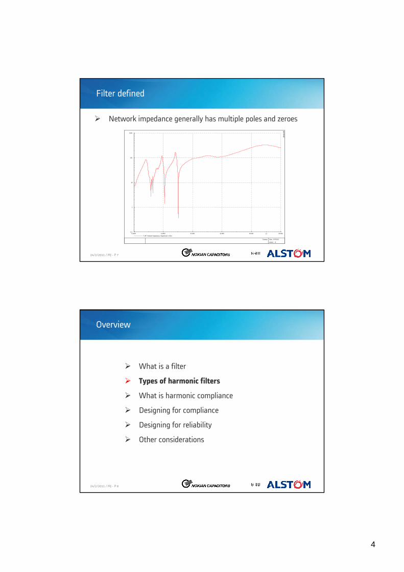
Network impedance generally has multiple poles and zeroes
20.00016.04012.0808.12004.16000.2000 [-]0.1
1
10
100
1000
T_BP: Network Impedance, Magnitude in Ohm
Zsweep
Date: 9/7/2010
Annex: /2
DIg
SILE
NT
24/2/2011 / MJ - P 8
Overview
What is a filter
Types of harmonic filters
What is harmonic compliance
Designing for compliance
Designing for reliability
Other considerations
5
24/2/2011 / MJ - P 9
Types of harmonic filter
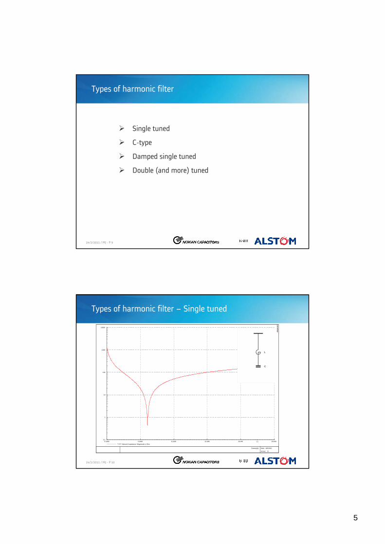
Single tuned
C-type
Damped single tuned
Double (and more) tuned
24/2/2011 / MJ - P 10
Types of harmonic filter – Single tuned
20.00016.04012.0808.12004.16000.2000 [-]0.1
1
10
100
1000
10000
T-ST: Network Impedance, Magnitude in Ohm
Zsweep(1)
Date: 9/6/2010
Annex: /3
DIg
SILE
NT

6
24/2/2011 / MJ - P 11
Types of harmonic filter – Single tuned
24/2/2011 / MJ - P 12
20.00016.04012.0808.12004.16000.2000 [-]0.1
1
10
100
1000
10000
T_BP: Network Impedance, Magnitude in Ohm
Zsweep(1)
Date: 9/6/2010
Annex: /3
DIg
SILE
NT
Types of harmonic filter – Damped single tuned

7
24/2/2011 / MJ - P 13
Types of harmonic filter – Damped single tuned
24/2/2011 / MJ - P 14
Types of harmonic filter – C-type
20.00016.04012.0808.12004.16000.2000 [-]0.1
1
10
100
1000
10000
T_CT: Network Impedance, Magnitude in Ohm
Zsweep(1)
Date: 9/6/2010
Annex: /3
DIg
SILE
NT

8
24/2/2011 / MJ - P 15
Types of harmonic filter – C-type
24/2/2011 / MJ - P 16
20.00016.04012.0808.12004.16000.2000 [-]0.1
1
10
100
1000
10000
T_DT: Network Impedance, Magnitude in Ohm
Zsweep(1)
Date: 9/6/2010
Annex: /3
DIg
SILE
NT
Types of harmonic filter – Double tuned

9
24/2/2011 / MJ - P 17
Types of harmonic filter – Double tuned
24/2/2011 / MJ - P 18
Types of harmonic filter – Comparison
Best Worst

10
24/2/2011 / MJ - P 19
Overview
What is a filter
Types of harmonic filters
What is harmonic compliance
Designing for compliance
Designing for reliability
Other considerations
24/2/2011 / MJ - P 20
Harmonic compliance
AS/NZS 61000-3-6

11
24/2/2011 / MJ - P 21
Harmonic compliance
The table is the beginning, not the end of the story
Network owners must set their own planning limits
Emission limits must then be calculated according to the procedures in the standard for every new load to ensure planning levels are not exceeded
These emission limits are the compliance limits
They are always lower than the planning limits
Emission limits are generally stated as voltage distortion at a busbar in the absence of other loads or background distortion
24/2/2011 / MJ - P 22
Harmonic compliance
Typical emissions limit table:

12
24/2/2011 / MJ - P 23
Overview
What is a filter
Types of harmonic filters
What is harmonic compliance
Designing for compliance
Designing for reliability
Other considerations
24/2/2011 / MJ - P 24
Design for harmonic compliance
Similar approach for compliance and reliability
Compliance looks at the network
Reliability looks at the filter components

13
24/2/2011 / MJ - P 25
Design for harmonic compliance
Loads•If at all possible, measure existing loads or at least voltage distortion
•Familiar with conditions on site
•Can be used to calibrate the model
•Take care of AS/NZS 61000-4-7
•Can be scaled for load changes
•Many variations / combinations are possible
•Determine harmonic current emission to be used
24/2/2011 / MJ - P 26
Design for harmonic compliance
Network•Existing model may be available
•Many “topology” variations are possible: fault level, loading, generation, lines connected
•Documented and agreed topology scenarios
•Many “network” variations are possible: voltage deviations, unbalance, frequency deviations
•Documented and agreed network variations
•Network model without knowledge of frequency dependency is useless
•Unbalanced harmonic load flow generally required
•Wherever possible, calibrate the model from measurements and explain any deviations

14
24/2/2011 / MJ - P 27
Design for harmonic compliance
Filters•Select a filter configuration that is feasible in terms of design and impact on the network
•Obtain as realistic as possible model for components: resistanceof reactors, manufacturing tolerances of components, sensitivityto aging, temperature
•Document the range of variations in L, C and R
•General guideline is to keep it as simple as possible: minimum steps, minimum components
24/2/2011 / MJ - P 28
Design for harmonic compliance
Compliance test•N possible topologies, K network parameters, and M filter parameters that can change N x K x M can easily result in thousands of discrete scenarios
•Each scenario produces sets of harmonic spectra at multiple busbars
•Compliance reached with optimal cost solution – capital and lifetime

15
24/2/2011 / MJ - P 29
Design for harmonic compliance
Compliance test•Common sense can reduce the number of results
•Automated analysis process is essential
•Sensible, compact approach to data representation
•Box and whisker
24/2/2011 / MJ - P 30
Overview
What is a filter
Types of harmonic filters
What is harmonic compliance
Designing for compliance
Designing for reliability
Other considerations

16
24/2/2011 / MJ - P 31
Design for reliability
Equipment to be rated to ensure reliable operation
Ratings according to manufacturing standards
IEC 60871 for capacitor units
AS/NZS 1028 (or IEC 60076-6) for reactors
Worst case expected continuous and short time ratings determined from modelling
24/2/2011 / MJ - P 32
Design for reliability
IEC 60871 for capacitor units
AS/NZS 1028 for reactors

17
24/2/2011 / MJ - P 33
Overview
What is a filter
Types of harmonic filters
What is harmonic compliance
Designing for compliance
Designing for reliability
Other considerations
24/2/2011 / MJ - P 34
Other considerations
Protection and control
Acceptable sound emissions
Insulation coordination / Impulse withstand
Switching transients
Seismic and wind loading
Standardisation
18
www.alstom.com