he power packs - hasmak
TRANSCRIPT

HYDRAULIC SYSTEMS DIVISION Outstanding Hydraulic Products, Service and Expertise, Worldwide
HE POWER PACKS

A complete, cost-effective
and flexible system
HE Power Packs allow you
to build up hydraulic units
simply and to your precise
specifications. The system
offers many advantages. It is
flexible and lends itself readily
to different applications.
It is very cost-effective,
because you no longer need
to hold complete units in
stock. You build up the re-
quired unit from a small
number of standard
components.
Other advantages include
low power consumption and
low noise levels. High qual-
ity down to the finest detail
ensures a long service life.
2
See Table of Contents
on Page 6
Pictures on front cover are used with the kind permission of eg: Atlet, BT, Huddig, Scania, Toro and Volvo Construction Equipment.

3

5
The following pages contain more information on
the HE power range. If you have any questions,
please do not hesitate to contact our local sales
office or distributor, or any of our factories.
HE 1000 & 2000
POWER PACKS
The HE 1000 & HE 2000 Power Packs are
based on a versatile platform that allows you
to combine motors with a variety of pumps
(pressure balanced and fixed clearance) and
reservoirs (plastic and steel; cylindrical and
rectangular). A unit can individually control
up to four (4) hydraulic cylinders. The core
of the system consists of an adapter with
alternative shapes and variable assembly
directions.
1 Motors
DC Operation
Series and Compound Wound motors
(12 V and 24 V). Efficient with long
service life, and low power consumption.
AC Operation
Flanges for AC motors permit the
use of standard high efficiency single or 3
phase motors (115 V, 230 V, and 460 V).
2 Adapters
All HE2000 units are equipped with the
same adapter size as shown above.4
Note:
The HE1000 adapter not shown here.
5 Relief Valves
Cartridge-style relief valves meet tough
demands for dependability and life
expectancy.
6 Constant-Flow Regulator
A built-in pressure-compensated flow
regulator can be added, providing
pressure compensated lowering speed
between 1 and 4 gpm regardless of load.
7 Oil Reservoir
The standard unit is equipped with a
translucent plastic reservoir with (.13 to 1.05
gal. / .5 to 4.0 ltr) usable volume or a steel
reservoir with (.18 to 4 gal. / .7 to 15.2 ltr.)
usable volume.
9 Check Valve
High performance cartridge check valve is
standard.
8 Valves
Screw-in cartridge valves with a
standard cavity are avilable in
2-way/2-position, 3-way/2-positiion,
3-way/3-position or 4-way/2-position
versions. Cetop 2, Cetop 3, and
additional cartridge valve blocks are
available for up to 4 individual functions.
3 Pumps
Pressure-balanced W Series (.24 to 5.7 cc
per rev. / .010 to .348 in.3 per rev.) and
fixed clearance GC Series (1.06 to 6.36 cc
per rev. / .065 to .388 in.3 per rev.)
gear pumps of our own design are
extremely efficient, with low noise.
4 Start Switches
12 VDC and 24 VDC, 3-pole and 4-pole,
standard duty and heavy duty; 1 & 3 PH,
115/230/460 VAC start switches with
high IP protection class and silverplated
contacts meet tough demands for a long
service life.
4
9
3
2
5
7
1
4
1
4
6
1
8
7
3
5
8
9
2

THE POWER OF HE
Pictures on front page are used with the kind permission of eg: Atlet, BT, Huddig, Scania, Toro and Volvo Construction Equipment.
Haldex Hydraulic Systems is one of the
world’s leading manufacturers of
hydraulic power packs. In recent years,
we have focused on strategically
important markets, and the result is a
new series of high performance
hydraulic power packs. The HE series
represents a further development of the
universal technical platform developed
by Haldex, worldwide.
HE Power Packs are optimized for
demanding applications. They are de-
signed for use in trucks operating in
harsh climates, or for heavy materials
handling with long service intervals.
Applications that demand high
performance and superb quality. We
have also prioritized customers’ wishes
for greater flexibility and better cost-
efficiency.
The result is an extremely versatile
platform, which uses standard com-
ponents and can handle most of the
applications the market demands. It lets
you cut your stock of hydraulic com-
ponents down to a minimum and radi-
cally reducing the need for specially
developed components.
HE Power Packs make it easier to
build short series of special applications
cost efficiently.
Haldex Hydraulic Systems is a
division of Haldex. Haldex is an
innovator in vehicle technology
supplying proprietary systems and
components for trucks, cars and
industrial vehicles, worldwide. With
4,100 employees and yearly sales
exceeding 7 billion Swedish Kronor,
Haldex is listed on the Stockholm Stock
Exchange (www.haldex.com).
The company operates globally and
enjoys global advantages: secure
supply l ines, close contact with
customers on development and a
universal technical platform that will
always fit your product. No matter
where in the world it is manufactured.
6
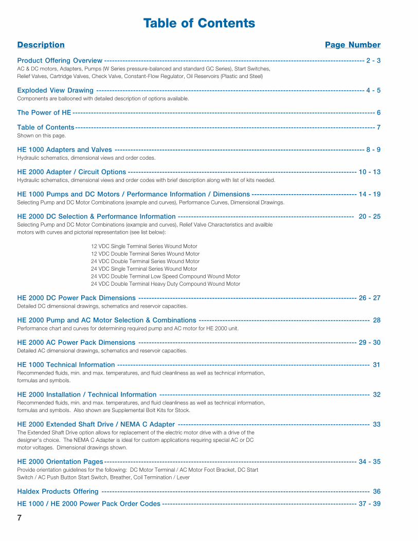
Table of Contents
Description Page Number
Product Offering Overview --------------------------------------------------------------------------------------------------- 2 - 3AC & DC motors, Adapters, Pumps (W Series pressure-balanced and standard GC Series), Start Switches,
Relief Valves, Cartridge Valves, Check Valve, Constant-Flow Regulator, Oil Reservoirs (Plastic and Steel)
Exploded View Drawing ------------------------------------------------------------------------------------------------------ 4 - 5Components are ballooned with detailed description of options available.
The Power of HE ------------------------------------------------------------------------------------------------------------------- 6
Table of Contents------------------------------------------------------------------------------------------------------------------ 7Shown on this page.
HE 1000 Adapters and Valves ----------------------------------------------------------------------------------------------- 8 - 9Hydraulic schematics, dimensional views and order codes.
HE 2000 Adapter / Circuit Options --------------------------------------------------------------------------------------- 10 - 13Hydraulic schematics, dimensional views and order codes with brief description along with list of kits needed.
HE 1000 Pumps and DC Motors / Performance Information / Dimensions ---------------------------------------- 14 - 19Selecting Pump and DC Motor Combinations (example and curves), Performance Curves, Dimensional Drawings.
HE 2000 DC Selection & Performance Information ------------------------------------------------------------------- 20 - 25Selecting Pump and DC Motor Combinations (example and curves), Relief Valve Characteristics and availble
motors with curves and pictorial representation (see list below):
12 VDC Single Terminal Series Wound Motor
12 VDC Double Terminal Series Wound Motor
24 VDC Double Terminal Series Wound Motor
24 VDC Single Terminal Series Wound Motor
24 VDC Double Terminal Low Speed Compound Wound Motor
24 VDC Double Terminal Heavy Duty Compound Wound Motor
HE 2000 DC Power Pack Dimensions ----------------------------------------------------------------------------------- 26 - 27Detailed DC dimensional drawings, schematics and reservoir capacities.
HE 2000 Pump and AC Motor Selection & Combinations ----------------------------------------------------------------- 28Performance chart and curves for determining required pump and AC motor for HE 2000 unit.
HE 2000 AC Power Pack Dimensions ----------------------------------------------------------------------------------- 29 - 30Detailed AC dimensional drawings, schematics and reservoir capacities.
HE 1000 Technical Information ------------------------------------------------------------------------------------------------ 31Recommended fluids, min. and max. temperatures, and fluid cleanliness as well as technical information,
formulas and symbols.
HE 2000 Installation / Technical Information -------------------------------------------------------------------------------- 32Recommended fluids, min. and max. temperatures, and fluid cleanliness as well as technical information,
formulas and symbols. Also shown are Supplemental Bolt Kits for Stock.
HE 2000 Extended Shaft Drive / NEMA C Adapter ------------------------------------------------------------------------- 33The Extended Shaft Drive option allows for replacement of the electric motor drive with a drive of the
designer’s choice. The NEMA C Adapter is ideal for custom applications requiring special AC or DC
motor voltages. Dimensional drawings shown.
HE 2000 Orientation Pages------------------------------------------------------------------------------------------------ 34 - 35Provide orientation guidelines for the following: DC Motor Terminal / AC Motor Foot Bracket, DC Start
Switch / AC Push Button Start Switch, Breather, Coil Termination / Lever
Haldex Products Offering ------------------------------------------------------------------------------------------------------ 36
HE 1000 / HE 2000 Power Pack Order Codes -------------------------------------------------------------------------- 37 - 39
7

8
HE 1000
HE 1000 Adaptors and Valves
The HE 1000 is designed for light
duty applications using the 3”
diameter motor, or for heavier
duty applications with the 4.5”
diameter motor. It’s smaller
envelope size, when compared
to it’s big brother, the HE 2000,
allows further flexibility for your
application.
The HE 1000 power pack can
be used in a Lift-Hold-Lower
circuit, a customer supplied
custom valve block package or
a 2-position 4-way valve circuit.
The HE 1000 adaptor includes
a check valve, relief valve and
most models can be equipped
with a pressure compensated
return flow control.
In addition to both vertical and
horizontal reservoirs, the HE1000
also offers weather protection
boots for the motor and start
switch terminals, and a single
acting pendant for remote
control.
Please note that adaptors are
shown from the reservoir side
on the following pages.
HE 1000 Adaptors
� �
�
NA000
Adaptor prepared for pressure
and return (P & T) circuit or a
customer supplied custom
valve block.
NA000

9
HE 1000 Adaptors (Cont.)
NL012
NL024
Adaptor prepared for 2-position
4-way solenoid cartridge valve
integrated in adapter. Adapter also
tapped and machined for a
customer supplied custom
manifold with pilot operated
checks.
NL012 & NL024
����
��������
����
����
��
� �
� �
�
��������
��� ���� ����� ��
���� �����
��������� ���
��� ��� !���"
######
######
�������� ����
��� �� ����
��� ���� �����
�
������
������
� �� �����
��������� ���
��� ���� �����
���
�!��
NE012
NE024
Adaptor prepared for lift-hold-lower
(LHL) applications, using 12 or 24 VDC
solenoid cartridge valves.
NO012
NO024
Same as shown, except with integrated
manual override in the solenoid
cartridge valve.
NE012 & NE024 / NO012 & NO024

View from Reservoir End
5.14 .88
AUX.OUTLETSAE -6O-RINGPORT
OUTLETSAE -6O-RINGPORT
View from Reservoir End
1.15
5.14 1.84
HE 2000 Adapter/Circuit Options
Each of the adapter options shown on the following pages
provide the complete circuit indicated by the corresponding
schematic. The order codes at the rear of this catalog
provide the vehicle for specifying the coil voltage, flow
control settings, relief valve settings and a number of other
options. The manifold adapters shown come with the
manifold for the circuit indicated. All adapters, manifolds,
coils, etc. are also available as stand alone kits which are
easily assembled.
BA (DC Version) or
CA (AC Version)
Adapter, P & T ports,
Relief Valve & Check Valve
Adapter kit 1303649
Port Plug 1300191
AC Motor Adapter Kit 1303549
(CA only)
Adapter kit 1300852
Solenoid Release valve kit 1303534
BB012 12 VDC Solenoid kit 1300914*
BB024 24 VDC Solenoid kit 1300915*
* Must order (1) 12 VDC or (1) 24 VDC.
BB (DC Version)
Adapter, Normally Closed
Solenoid Lowering Valve.85
Top ViewShown with optional flow control.
See Model Code V for flow
control options - page 26.
Hydraulic Schematic
SAE -6 O-RING
PORT
SAE -6
O-RING
PORT
Top View Hydraulic Schematic
M
P T
M
10
AC MOTOR
ADAPTER PLATE
(CA Only)
1.15
SAE -6O-RING PORT
STARTSWITCH
RELEASE
HOLD
PUMP
5.695.14
45º
View from Reservoir EndBE
Manual Normally Closed
Lowering Adapter with DC Contactor
Adapter kit 1300852
Manual Release valve kit w/
pilot solenoid contactor 1300192
NOTE: Motor solenoid start switch still
required.
Top View
1.093
1.312
5.11
1.59
.090
1.120
.862
Hydraulic Schematic
M
12º
AUX.OUTLETSAE -6O-RINGPORT
OUTLETSAE -6O-RINGPORT
View from Reservoir EndCB (AC Version)
Adapter, Normally Closed
Solenoid Lowering Valve
Top ViewShown with optional flow control.
See Model Code V for flow
control options - page 26.
Hydraulic Schematic
M
Adapter kit 1303649
Solenoid Release valve kit 1303534
CF115 110 VAC Solenoid kit 1303576*
CF230 230 VAC Solenoid kit 1303577*
AC Motor Adapter kit 1303549
* Must order (1) 115 VAC or (1) 230 VAC.
AC MOTOR
ADAPTER PLATE
1.312
1.093
5.11
1.312
1.093
Ø 6.52
Ø 6.52
1.59
.862
1.88
.85
1.59
1.15
5.14 1.84
1.15
1.59
1.312
1.093
5.11
1.15
5.11
PAD A
PAD A
PAD A
PA
D B
PA
D B
PA
D B
PAD A
PA
D B

HE 2000 Adapter/Circuit Options (continued)
11
CF
Manifold Adapter w/3-position, 4-way
Valve (motor spool) (AC Version)
Hydraulic SchematicTop ViewView from Reservoir End
Adapter kit 1303650
Manifold kit 1300866
Motor Spool Valve 1303382
Plug (P. O. Check cavity) 1303540
CF115 115 VAC Solenoid kit 1303576*
CF230 230 VAC Solenoid Kit 1303577*
Riser block (required for
AC units w/manifolds) 1300855
AC Motor Adapter kit 1303549
* Must order (2) 115 VAC or (2) 230 VAC.
¼” DUAL SPADE
CONNECTORS
.28
C2
C1
.86
3.31
3.014.38
Ø 6.52
.57
A.C. MOTOR
ADAPTOR PLATE
3.381.88
M
P T
S2 S1
C1 C2
RISER
BLOCK
1.47
1.47
.625
5.14
S1
S2
2XSAE-6O-RINGPORTS(OPPOSITESIDE)
1.15
RISERBLOCKREQUIREDWITHA.C.MOTOR
PAD A
PAD
B
5.51
5.14 3.84
SAE -6O-RING PORT
View from Reservoir End
1.25
Top View
ø 6.52
1.59
Hydraulic Schematic
M
CE
AC Manual Normally Closed
Lowering Valve Adapter
Adapter kit 1303649
Manual Release valve kit 1303533
AC Motor Adapter kit 1303549
1.15
1.87 A.C.
MOTOR
ADAPTOR
PLATE
BH
Manifold Adapter w/3-position, 4-way
Valve (motor spool)
(DC Version w/Double P.O. Check)
Hydraulic SchematicTop View
Adapter kit 1303650
Manifold kit 1300866
Motor Spool Valve 1303382
Double P. O. Check Valve 1303538
BH012 12 VDC Solenoid kit 1300914*
BH024 24 VDC Solenoid kit 1300915*
* Must order (2) 12 VDC or (2) 24 VDC.
¼” DUAL SPADECONNECTORS
C2
C1
.86
3.31
.57
4.383.01
3.381.58
C1 C2
S2 S1P T
M
View from Reservoir End
1.47
.625
5.14
S1
S22X SAE-6O-RINGPORTS(OPPOSITESIDE)
1.15
PAD A
PAD
B
BF
Manifold Adapter w/3-position, 4-way
Valve (motor spool) (DC Version)
Hydraulic Schematic
Adapter kit 1303650
Manifold kit 1300866
Motor Spool Valve 1303382
Plug (P. O. Check cavity) 1303540
BF012 12 VDC Solenoid kit 1300914*
BF024 24 VDC Solenoid kit 1300915*
* Must order (2) 12 VDC or (2) 24 VDC.
Top View
.28
¼” DUAL SPADECONNECTORS
C1
C2
.86
3.014.38
.57
3.31
3.381.58
M
P TS1S2
C1 C2
View from Reservoir End
1.47
.625
2XSAE-6O-RINGPORTS(OPPOSITESIDE)
5.14
S1
S2
1.15
PAD A
PAD
B
.49
PAD A
PAD
B

.625
PAD
B
2XSAE-6O-RINGPORTS(OPPOSITESIDE)
1.15
5.14 1.47
Adapter kit 1303650
Manifold kit 1300866
Tandem Center Valve 1303530
Plug (P. O. Check cavity) 1303540
CJ115 115 VAC Solenoid kit 1303576*
CJ230 230 VAC Solenoid kit 1303577*
Riser block (required for
AC units w/manifolds) 1300855
AC Motor Adapter kit 1303549
* Must order (2) 115 VAC or (2) 230 VAC.
CJ
Manifold Adapter w/3-position, 4-way
Valve (tandem center spool) (AC Version)
Hydraulic SchematicTop ViewView from Reservoir End
HE 2000 Adapter/Circuit Options (continued)
Adapter kit 1303650
Manifold kit 1300866
Tandem Center Valve 1303530
Plug (P. O. Check cavity) 1303540
BJ012 12 VDC Solenoid kit 1300914*
BJ024 24 VDC Solenoid kit 1300915*
* Must order (2) 12 VDC or (2) 24 VDC.
BJ
Manifold Adapter w/3-position, 4-way
Valve (tandem center spool)
(DC Version)
View from Reservoir End Top View
1.47
.625
Hydraulic Schematic
BR
Manifold Adapter w/Solenoid Operated,
2-position, 4-way Valve (DC Version)
Top View Hydraulic SchematicView from Reservoir End End
Adapter kit 1303650
Manifold kit 1300866
Normally Open Valve 1303529
Plug (P. O. Check cavity) 1303540
CR115 115 VAC Solenoid kit 1303576*
CR230 230 VAC Solenoid kit 1303577*
Riser block (required for
AC units w/manifolds) 1300855
AC Motor Adapter kit 1303549
* Must order (1) 115 VAC or (1) 230 VAC.
CR
Manifold Adapter w/Solenoid Operated,
2-position, 4-way Valve (AC Version)
Hydraulic SchematicTop ViewView from Reservoir End
5.14
S1
S2
12
PAD
B
1.15
2X SAE-6O-RINGPORTS(OPPOSITESIDE)
PAD A
¼” DUAL SPADE
CONNECTORS
.28
REF
C2
C1
.86
3.31 REF
.57
4.383.01
1.583.38
M
P TS2 S1
C1 C2
PAD A
M
PT
C1 C2
RISER BLOCK
S1S2
¼” DUAL SPADE
CONNECTORS
.28
REF
C2
C1
3.31 REF
.57
A.C. MOTOR
ADAPTOR
PLATE3.38
1.881.58
.86
1.47
RISER
BLOCK
REQUIRED
WITH
A.C.
MOTOR
S1
S2
PAD
B
1.15
5.14 2.94
2.13
2XSAE-6O-RINGPORTS(OPPOSITESIDE)
PAD A
M
P T
C1 C2¼” DUAL SPADE
CONNECTORS
.28
REF
C2
C1
.86
4.383.01
1.85
REF
.57
3.38
1.58
M
PT
RISERBLOCK
C1 C2
1.47
PAD
B
PAD A 2XSAE-6O-RINGPORTS(OPPOSITESIDE)
1.15
5.14 2.94
2.10
¼” DUAL SPADE
CONNECTORS
.28 REF
C2
C1
1.85 REF
.57
ø 6.524.383.01
A.C.MOTORADAPTORPLATE
.86
1.581.88
3.38
4.383.01
ø 6.52
Adapter kit 1303650
Manifold kit 1300866
Normally Open Valve 1303529
Plug (P. O. Check cavity) 1303540
BR012 12 VDC Solenoid kit 1300914*
BR024 24 VDC Solenoid kit 1300915*
* Must order (1) 12 VDC or (1) 24 VDC.

Adapter kit 1303650
HE 2000 Adapter/Circuit Options (continued)
BS
Manifold Adapter w/Solenoid Operated,
2-position, 4-way Valve
(DC Version w/P.O. Check)
Adapter kit 1303650
Manifold kit 1300866
Normally Open Valve 1303529
BS012 12 VDC Solenoid kit 1300914*
BS024 24 VDC Solenoid kit 1300915*
Single P.O. Check Valve 1303539
* Must order (1) 12 VDC or (1) 24 VDC.
Adapter kit 1303650
D03 Manifold kit 1300854
Bolt Kit 1300865
DA
Manifold Adapter w/Single DO3 Valve
Manifold (DC Version)
DB
Manifold Adapter w/Single DO3 Valve
Manifold (AC Version)
DC
Manifold Adapter w/Double DO3 Valve
Manifold (AC Version Only)
Adapter kit 1303650
Primary D03 Manifold kit 1300854
Primary D03 Manifold kit 1300854
Bolt Kit 1300858
Riser block (required for
AC units w/manifolds) 1300855
AC Motor Adapter kit 1303549
Hydraulic SchematicTop ViewView from Reservoir End
Hydraulic Schematic
BLOCK WITHSTANDARDSAE D03INTERFACEP T
M
Top View
1.58
.862
2.406 + .005
.297
.485
1.937
View from Reservoir End
.234.643
1.28
.156 ø
.190 DP.
.250 øTYP. 4
#10-24UNC-2B.375 MFTTYP. 4
.328
1.937
.609
SAE -6 O-RINGPORTS (BOTH SIDES)(OPPOSITE SIDE)
MOUNTINGFACE OPPOSITESIDE
Hydraulic Schematic
BLOCK WITH
STANDARD SAE
D03 INTERFACE
P T
M
RISER BLOCK
Top View
1.97
A.C. MOTORADAPTOR PLATE
View from Reservoir End
1.47
3.41
.97
1.15 SAE -6 O-RINGPORTS (BOTH SIDES)(OPPOSITE SIDE)
MOUNTING FACEOPPOSITE SIDE
Hydraulic Schematic
M
BLOCK WITH
STANDARD SAE D03
INTERFACE
BLOCK WITH
STANDARD SAE D03
INTERFACE
RISER BLOCK
P
P
T
T
Top View
A.C. MOTORADAPTOR PLATE
1.97
View from Reservoir End
SAE -6 O-RING PORTS(BOTH SIDES)(OPPOSITE SIDE)
5.34
.97 .97
3.41
1.47
1.15
3.75
MOUNTINGFACEOPPOSITESIDE
1.053
.031
5.14
1.15
1.58.862
5.14
6.52
6.52
1.585.14
.862
1.221
DM
Manifold Adapter (DC Version)
AM
Manifold Adapter (AC Version)
Adapter kit 1303650
AC Motor Adapter Kit 1303549
Hydraulic Schematic
P T
M
Manifold ViewView from Reservoir End
1.15
5.14 1.58 AC MOTORADAPTERNAMEPLATE
2X 1.212X .862X .24
Pø .48
1.31
1.09
ø .66T
ø 6.52
2.08
1.08
1.00
.50
4X 1/4-20UNC-2B.40 MFT
Adapter kit 1303650
Primary D03 Manifold kit 1300854
Bolt Kit 1300857
Riser block (required for
AC units w/manifolds) 1300855
AC Motor Adapter kit 1303549
13
M
C1 C2
P T
.86
.49 REF
¼” DUAL SPADECONNECTORS
C2
C1
1.58
3.38
3.014.38
.57
1.85 REF
PAD
B
PAD A
PAD
B
PAD A
PAD
B
PAD A
PAD
B
PAD A
2XSAE-6O-RINGPORTS(OPPOSITESIDE)
.6251.15
5.14 1.47
PAD
B
PAD A

14
HE 1000 PUMPS AND DC MOTORS
12MG32, Ø 80mm
S2
(m
in)
S3
(%
)
S2 (min)
l (amp)
l (a
mp
)
160
120
80
40
00
5
10
15
20
25
S3 (%)
5
Q (l
/min
)
Q=1.22cc
Q=0.84cc
Q=0.48cc
Q=0.24cc
50 100 150 2000
30
60
90
120
150
180
210
I (am
p)
p(bar)
I=0.24cc
I=0.48cc
I=0.84cc
I=1.22cc
80
90
3,3
The HE series is equipped with motors
for 12 or 24 VDC. These compound
motors provide extremely high power
output and meet tough load require-
ments. A thoughtful basic design and
long-lasting carbon brushes cut down
on maintenance requirements. All
motors are manufactured by the
Hydraulic Systems Division of Haldex
to ensure maximal system optimization,
performance and quality.
MAKE THE OPTIMAL CHOICE
OF PUMP AND MOTOR
On the following pages, you will
find our range of DC motors and
pumps.
Important parameters to consider
in choosing the correct unit are
flow in l/min, pressure in bars, and
duty cycle. In some cases, allow-
able amp consumption is a factor
too, due to restricted battery capa-
city.
Our curves permit easy com-
parison at a constant voltage
measurement.
How to read the curves:
When pressure and flow are
determined, the amperage can
be read from the pump/motor
curve. The amperage is then
transferred to curve 2.
The amperage corresponds to
an S2 and an S3 value. These
values represent two ways of
calculating duty capability.
S2 is the number of minutes a
unit can operate at a certain
workload before reaching the
maximum allowable temperature.
After this, the unit must cool down
until the motor temperature is less
than 2°C from the ambient tem-
perature before the same S2
value can be applied again.
S3 is the maximum time in %
per 10 minute period that a unit
can work at a certain pressure/
workload. For example an S3
value of 30% = 3 min. for each
10 min. period, over and over
again.
Pump motor
Corresponding motor
Example: 3,3 l/min at 90 bar and 80 amp on pump motor curve
gives S2 = 3 min and S3 = 11% at corresponding motor curve.

HE 1000 Performance Information
15
25
20
15
10
5
0
S2 (min)
S3 (%)I (amp)
I (a
mp)
0
40
80
120
160
S2 (m
in)
S3 (%
)
p(bar)
MG pump motor 12 VDC He1000 Ø 80 mmViscosity 32 cSt at 40ºC Voltage 12 VDC constant
5
Q (l/
min
)
Q=1.22cc
Q=0.84cc
Q=0.48cc
Q=0.24cc
50 100 150 2000
30
60
90
120
150
180
210
I (am
p)
I=1.22cc
I=0.84cc
I=0.48cc
I=0.24cc
Corresponding motor
Code Motor
10 12MG32-HE
11 12MG32THE
HE 1000 MG Pump/Motor w/ 12 VDC Ø 80 mm Motor
Viscocity 32 cSt at 40°C. Voltage 12 VDC constant
Code Pump
02 0,24cc
05 0,48cc
08 0,84cc
12 1,22cc
HE 1000 Performance Information
Corresponding motor
5
Q=1.22cc
Q=0.84cc
Q=0.48cc
Q=0.24cc
I=0.24cc
I=0.48cc
I=0.84cc
I=1.22cc
I (a
mp
)
Q (l/
min
)
50 100 150 2000
40
80
120
p(bar)
25
20
15
10
5
0
S2 (min)
S3 (%)I (amp)
I (a
mp)
0
40
80
120
160
S2 (m
in)
S3 (%
)
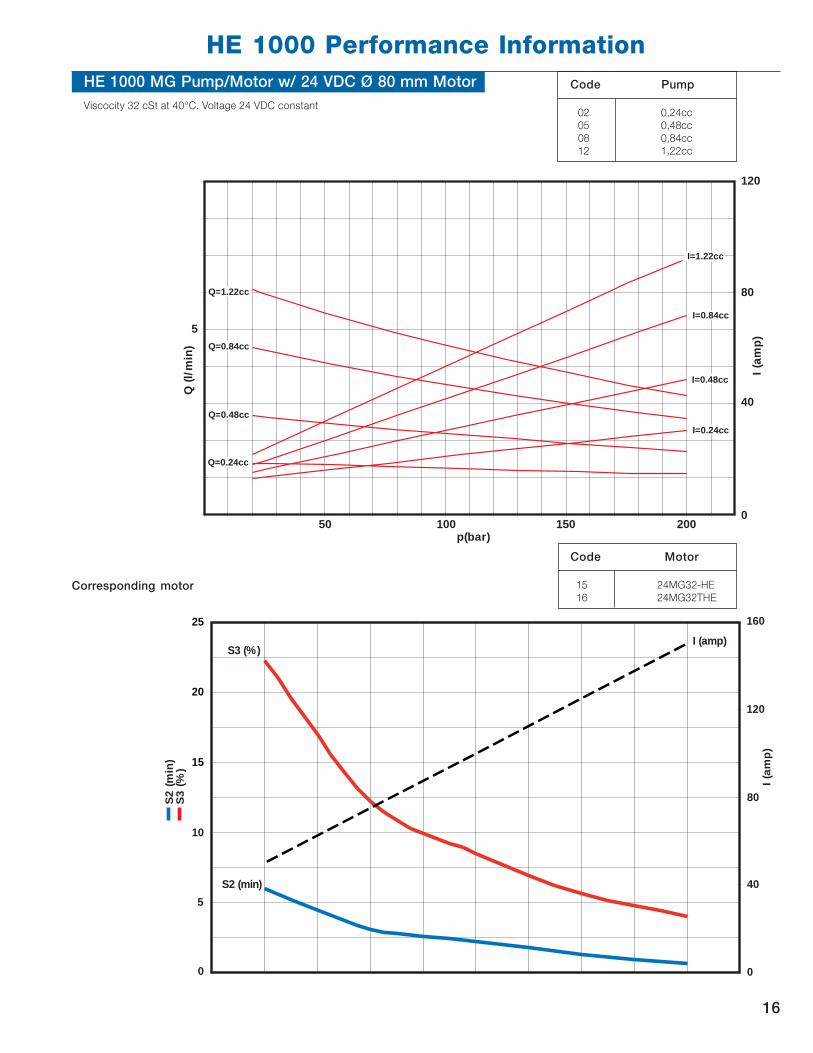
Code Motor
15 24MG32-HE
16 24MG32THE
HE 1000 MG Pump/Motor w/ 24 VDC Ø 80 mm Motor
Viscocity 32 cSt at 40°C. Voltage 24 VDC constant
16
Code Pump
02 0,24cc
05 0,48cc
08 0,84cc
12 1,22cc
17
HE 1000 Performance Information
Corresponding motor
Viscosity 32 cSt at 40 C Voltage 12 VDC constant
Q=1.2cc
Q=0.8cc
Q=0.48cc
Q=0.24cc
I=0.24cc
I=0.48cc
I=0.8cc
I=1.2cc
300
250
200
150
100
50
020015010050
5
10
15
p (bar)
Q (l/
min
)
I (am
p)
,
I (amp)S2 (min)
S3 (%)
90
80
70
60
50
40
30
20
10
0
S2 (m
in)
S3 (%
)
300
250
200
150
100
50
0
I (a
mp)
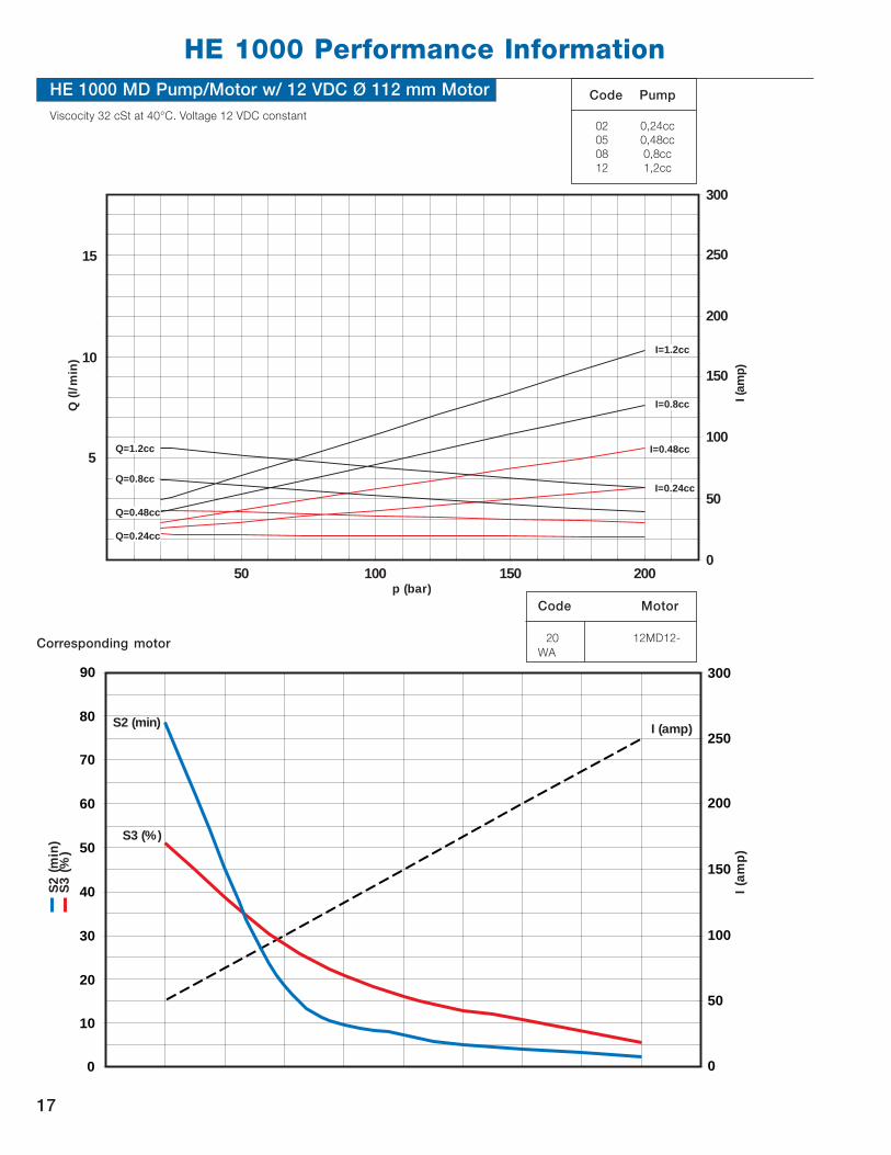
HE 1000 MD Pump/Motor w/ 12 VDC Ø 112 mm Motor
Viscocity 32 cSt at 40°C. Voltage 12 VDC constant
Code Motor
20 12MD12-
WA
Code Pump
02 0,24cc
05 0,48cc
08 0,8cc
12 1,2cc

18
HE 1000 Performance Information
Corresponding motor
y g
Q=1.2cc
Q=0.8cc
Q=0.48cc
Q=0.24cc
p (bar)
Q (l/
min
)
5
10
15
20280
240
200
160
120
80
40
020015010050
I (am
p)
I=0.24cc
I=0.48cc
I=0.8cc
I=1.2cc
I (amp)
,
S2 (min)
S3 (%)
I (a
mp)
S2 (m
in)
S3 (%
)
25
20
15
10
5
0
60
120
180
240
300
0
Code Motor
25 24MD22-WA
26 24MD22TWA
Viscocity 32 cSt at 40°C. Voltage 24 VDC constant
HE 1000 MD Pump/Motor w/ 24 VDC Ø 112 mm Motor Code Pump
02 0,24cc
05 0,48cc
08 0,8cc
12 1,2cc

Reservoir A B Codes
V = Usable volume Horizontal Vertical
V = 0.5 L Ø Cylindrical 353 381 AA AB
V = 1.0 L Ø Cylindrical 430 458 AC AD
V = 1.5 L Ø Rectangular 316 344 AE AF
V = 2.0 L Ø Rectangular 351 379 AG AH
V = 2.5 L Ø Rectangular 386 414 AJ AK
V = 4.0 L Ø Rectangular 486 514 AL AM
HE 1000 Power Pack Dimensions
HE 1000 w/ 12/24 VDC Ø 80 mm Motor
HE 1000 w/ 12/24 VDC Heavy Duty Ø 112 mm Motor
19

Selecting Pump and DC Motor CombinationsRefer to the appropriate “pump/motor” curve for your application voltage. Find the required flow at working pressure.
Refer to the amp draw axis to determine the amp draw for the selected pump/motor combination. Note: Performance
will vary depending on whether a pressure balanced or fixed clearance pump is chosen. On the “S2 (absolute continu-
ous on-time)/S3 (percentage on-time)” curve you can determine the maximum duty cycle of your selected pump/motor
combination. Note: All S3 curves are based on a 5 minute duty cycle.
Following is an example of determining this information:
Assuming a 2.6 GPM at 2000 PSI is required, the performance graph indicates a 2.5 cc/rev. pump is needed. The
performance graph also shows a requirement of 165 amps with a W300 Pressure Balanced Pump. The S2/S3 curve at
that amp draw has a S2 (absolute continuous on-time) of 1 minute, 30 sec. At that point, the motor would have to be
turned off to allow cooling to ambient temperature. The motor could then be run for another 1 minute, 30 sec.
The S3 (percentage on-time) curve shows a maximum percentage on time of 8.0%, which means the motor can be
operated for 24 seconds on, 276 seconds off, continuously.
HE 2000 DC Selection / Performance Information
The following pages include performance information for combinations of pumps and DC motors as well as pumps and
AC motors. Pages 12-16 feature pump/DC motor performance curves. Page 28 features pump/AC motor performance
curves.
Relief Valve Characteristics
“Cracking pressure” is defined as when the relief valve begins to open and starts bypassing flow to the reservoir (defined
as .25 GPM flow loss).
Relief valve cracking pressure is approximately 80% of the full bypass pressure and flow (i.e., if the relief valve pressure is
to be set at 2500 PSI full bypass, then 2500 x 0.8 = 2000 PSI is the cracking pressure).
“Full bypass pressure and flow” is defined as when the relief valve is completely open and all flow is going back to the
reservoir.
“Working pressure” should always be at or below the cracking pressure for maximum efficiency.
1 min.
30 sec.
Duty
Cycle
8.0%
On-
Time
165
Amps2.6
GPM
20

6.6
4.4
ø 4.4
Performance for HE 2000 12 VDC Single Terminal Series Wound Motor,
P/N 1300027
Note: Motor damage may result from operation outside the curve parameters as shown above.21

Performance for HE 2000 12 VDC Double Terminal Series Wound Motor,
P/N 1300618
Note: Motor damage may result from operation outside the curve parameters as shown above.
6.3
5.3
ø 4.5
22

Performance for HE 2000 24 VDC Double Terminal (P/N 1300619)
and Single Terminal (P/N 1300912) Series Wound Motors
Note: Motor damage may result from operation outside the curve parameters as shown above.
6.3
5.3
ø 4.5
NOTE:
1300912 IS THE SAME AS A
1300619 WITH A GROUND STRAP
ON EITHER MOTOR TERMINAL.
23

Performance for HE 2000 24 VDC Double Terminal Low Speed
Compound Wound Motor, P/N 1300913
Note: Motor damage may result from operation outside the curve parameters as shown above.
6.3
5.3
ø 4.5
24

Note: Motor damage may result from operation outside the curve parameters as shown above.
Performance for HE 2000 24 VDC Double Terminal Heavy Duty
Compound Wound Motor, P/N 1303551
10.1
5.7
ø 5.1
25

HE 2000 DC Power Pack Dimensions
Power Pack with 4.8 Inch Cylindrical Reservoir
9/16-18 SAEOUTLETPORT
1.8 2.6
.5
ø 4.8 1.9
1.9
1.9 1.9
5.1
6.0
CHECK VALVE
4X 3/8-/16 UNC-2B.63 MIN FULL THREADMOUNTING HOLES
2.6
6.3APPROX.
INSTALLATION NOTES: Motors, center adapters and reservoirsmay be rotated in many combinations of 90 degree increments formaximum flexibility.
See Model Code XI for Tube Options - page 39.
6.0
ø 4.5
6.3
.7
1.6
9/16-18 SAEALT. OUTLET PORT(NORMALLY PLUGGED)
“A”
9/16-18 SAERETURN PORT
2.3
ADJ.RELIEFVALVE 40 MICRON BREATHER
3/8-18 NPT FILL PORT
CAPACITY / TYPE
1.0 QT. CYLINDRICAL
1.5 QT. CYLINDRICAL
2.0 QT. CYLINDRICAL
3.0 QT. CYLINDRICAL
“A” (INCHES)
5.6
7.5
9.0
12.0M
Power Pack with 6.6 Inch Single Piece Cylindrical Reservoir
CUSTOMER CONTROLVOLTAGE CONNECTION(POSITIVE) 10-32 UNF25 IN-LBS MAX. TORQUE
CUSTOMER POWERCONNECTION (POSITIVE)5/16-24 UNF35 IN-LBSMAX. TORQUE
.9 1.8
.5
1.1
1.3
1.9
1.9 2.5
5.1
2.6
CHECK VALVE4X 3/8-16 UNC-2B.6 MIN FULL THREADMOUNTING HOLES
1.8
6.0
4.2
4.2
7.9 APPROX.
ø 6.6
A6.3
.7
1.6
OUTLET PORT9/16-18 SAE
TORQUENUT48-50IN-LBS.
9/16-18 SAEALT. OUTLET PORT(NORMALLY PLUGGED)
CUSTOMER CONTROLGROUND CONNECTION(NEGATIVE) 5/16-24 UNF35 IN-LBS MAX. TORQUE
CUSTOMERGROUNDCONNECTION(NEGATIVE)5/16-24 UNF35 IN-LBSMAX. TORQUE
M
CAPACITY
1.0 GAL. (3.9 L.)
1.5 GAL. (5.7 L.)
2.0 GAL. (7.6 L)
3.0 GAL. (11.3 L.)
“A”
8.34 IN. (212 MM)
12.6 IN. (320 MM)
15.3 IN. (390 MM)
22.3 IN. (566 MM)
See Model Code XI for Tube Options - page39.
CUSTOMERS CONTROL VOLTAGECONNECTION (POSITIVE) #10-32 UNF25 IN-LBS MAX. TORQUE
CUSTOMERS POWERCONNECTION (POSITIVE)5/16-24 UNF35 IN-LBS MAX. TORQUENOTE:
FOR SINGLE TERMINAL
MOTORS, GROUNDING
OCCURS WHEN THE
UNIT IS BOLTED TO THE
VEHICLE. 26

HE 2000 DC Power Pack Dimensions (continued)
Power Pack with Rectangular Reservoir
M
CUSTOMERPOWER CONNECTION(POSITIVE)5/16-24 UNF35 IN-LBSMAX. TORQUE
7.1
4.2
.9 1.8
1.9 1.9
4.0
2.52.5
8.0
AUX. PRESSUREPORT9/16-18 SAE(STEEL PLUGGED)
2.6
6.5
OUTLETPORT9/16-18 SAE(PLASTICPLUG) 7.8 APPROX.
40 MICRON BREATHER3/8-18 NPT FILL PORT
RELIEF VALVE
2.96.0
4.2
1.6
1.6 A
CUSTOMER CONTROLVOLTAGE CONNECTION(POSITIVE) 10-32 UNF25 IN-LBS MAX. TORQUE
6.3
.7
3.7
CAPACITY
2.5 GAL. (9.5 L.)
4.0 GAL. (15.1 L.)
“A”
12.0 IN. (305 MM)
18.5 IN. (470 MM)
CUSTOMER CONTROLGROUND CONNECTION(NEGATIVE) 10-32 UNF25 IN-LBSMAX. TORQUE
CUSTOMER GROUNDCONNECTION(NEGATIVE) 5/16-24 UNF35 IN-LBS MAX. TORQUE
See Model Code XI for Tube Options - page39.
27

HE 2000 Pump and AC Motor Selection / Combinations
The following charts and curves provide all the information required to specify a pump and AC motor for the HE 2000.
The nominal rated horsepower for TENV motors is based on a 30 minute duty cycle. The nominal rated horsepower for
TEFC motors is based on continuous duty. For 50 Hz operation, pump flow and horsepower shown below need to be
derated by approximately 20%.
The curves below demonstrate the relationship between flow and pressure to determine horsepower required. Once
horsepower required is determined, refer to the above chart to determine the appropriate motor for the required duty
cycle.
60 Hertz Ratings
Max. cc/rev. Pullup Breakdown
HP HP HP Starting at Torque at Torque at Dimensions
Model 5 min. 15 min. 30 min. Line Low 2500 psi Line Voltage Line Voltage 5 Min. Duty HP
Code Catalog P/N HP Phase Hz Voltage Encl. RPM Rated Rated Rated Voltage Voltage Low Voltage Ft-lbs. Ft-lbs. Nominal Amp Draw L H K
60 1300916 . 5 three 50/60 208-230/460 TENV 1425/1725 1 0.75 0.5 230 188 1.6 6.2 9.0 3.5 A @ 230 V 5.8 6.8 4.0
62 1300918 1 three 50/60 208-230/460 TENV 2850/3450 2.5 1.8 1 230 188 1.6 6.4 6.7 8.4 A @ 230 V 5.8 6.8 4.0
63 1300919 1 three 50/60 208-230/460 TEFC* 2850/3450 2.5 1.8 1 230 188 1.6 6.4 6.7 8.4 A @ 230 V 7.5 7.3 4.0
64 1300920 1 single 60 115/208-230 TENV 3450 2.5 1.8 1 115 99 1.6 5.7 6.9 28.6 A @ 115V 7.8 8.8 4.3
65 1300921 1 single 50/60 115/208-230 TEFC* 2850/3450 2.5 1.8 1 115 99 1.6 5.1 6.0 28.6 A @ 115V 9.5 8.8 4.3
66 1300922 1 three 50/60 208-230/460 TENV 1425/1725 3 2 1 230 188 3.2 12.3 17.1 8.4 A @ 230 V 6.8 6.8 5.0
67 1300923 1 single 60 115/208-230 TENV 1725 2 1.5 1 115 99 3.2 9.1 10.8 8.5 A @ 230 V 9.3 9.0 5.8
68 1300924 2 single 60 115/208-230 TENV 3450 4 3 2 115 99 2.1 7.4 7.7 27 A @115 V 9.8 8.8 6.2
69 1300925 2 single 50/60 115/208-230 TEFC* 2850/3450 3 2.5 2 115 99 2.1 5.4 8.0 30.2 A @ 115V 11.0 8.8 5.8
70 1300926 2 three 50/60 208-230/460 TENV 1425/1725 4 3.5 2 230 188 6.4 24.0 26.5 5.7 A @ 230V 8.8 6.8 5.3
71 1300927 2 single 60 115/208-230 TENV 1725 3 2.5 2 115 99 4.8 17 19 35 A @ 115 V 9.8 8.6 6.3
72 1300928 3 three 50/60 208-230/460 TENV 2850/3450 4.9 3.8 3 230 188 3.2 12.6 14.6 13.7 A @ 230 V 6.8 6.8 3.3
73 1300929 3 three 50/60 208-230/460 TEFC* 2850/3450 4.9 3.8 3 230 188 3.2 12.6 14.6 13.7 A @ 230 V 9.5 6.8 4.3
74 1300930 2 . 5 single 50/60 208-230 TENV 2850/3450 3.5 3 2.5 230 188 3.7 9.3 10.7 20.1 A @ 230 V 9.8 9.1 6.2
* NOTE: For TEFC motors the 30 minute rated horsepower is a continuous rating.
28

HE 2000 AC Power Pack Dimensions
Power Pack with 4.8 Inch Cylindrical Reservoir
1.5
1.5
5.0 6.5
3X ø .9KNOCKOUT
L
K
1.9
2.4TORQUENUT:48-50 IN-LBS
TORQUE CARTRIDGETO: 144-180 IN-LBS
1.2
.3
DETAIL OF MTG. SLOTS
A
ø 4.8
H
3.5
9/16-18 S.A.E.OUTLET/RETURN PORT(PLASTIC PLUG)
2.4
2.4
6.5
1.3
4.35.4
1.8
.5
RELIEF VALVE
7/16-20 SAEAUX. RETURN(STEEL PLUG)
9/16-18 S.A.E.OUTLET/RETURN PORT(STEEL PLUG)
CAPACITY
1.0 QT. [.9 L]
1.5 QT. [1.4 L]
2.0 QT. [1.9 L]
3.0 QT. [2.8 L]
LENGTH “A”
5.6 IN. [143 MM]
7.5 IN. [191 MM]
9.0 IN. [229 MM]
12.0 IN. [305 MM]
SEE A.C. MOTOR TABLE ON PAGE 28
FOR LETTER DIMENSIONS H, L AND K
See Model Code XI for Tube Options -page 28.
Power Pack with 6.6 Inch Single Piece Cylidrical Reservoir
CAPACITY
1.0 GAL. [3.8 L]
1.5 GAL. [5.7 L]
2.0 GAL. [7.6 L]
3.0 GAL. [11.3 L]
LENGTH “A”
8.3 IN. [212 MM]
12.6 IN. [320 MM]
15.3 IN. [390 MM]
22.3 IN. [567 MM] SEE A.C. MOTOR TABLE ON PAGE 28
FOR LETTER DIMENSIONS H, L AND K
6.5
2.42.4
6.4
9.6
.1
6.8
4.3
1.1
1.3
OPTIONALPUSHBUTTONSTART SWITCH
4.2L
K
H
A
4.0
3.0
ø 7.2
1.3
1.9
.7OUTLET/RETURN9/16-18 SAE
3X ø .9KNOCKOUT
ø 6.6
1.2
.3
DETAIL OF MTG. SLOTS
M
PUSH TO
LOWER
See Model Code XI for Tube Options -page 28.
29
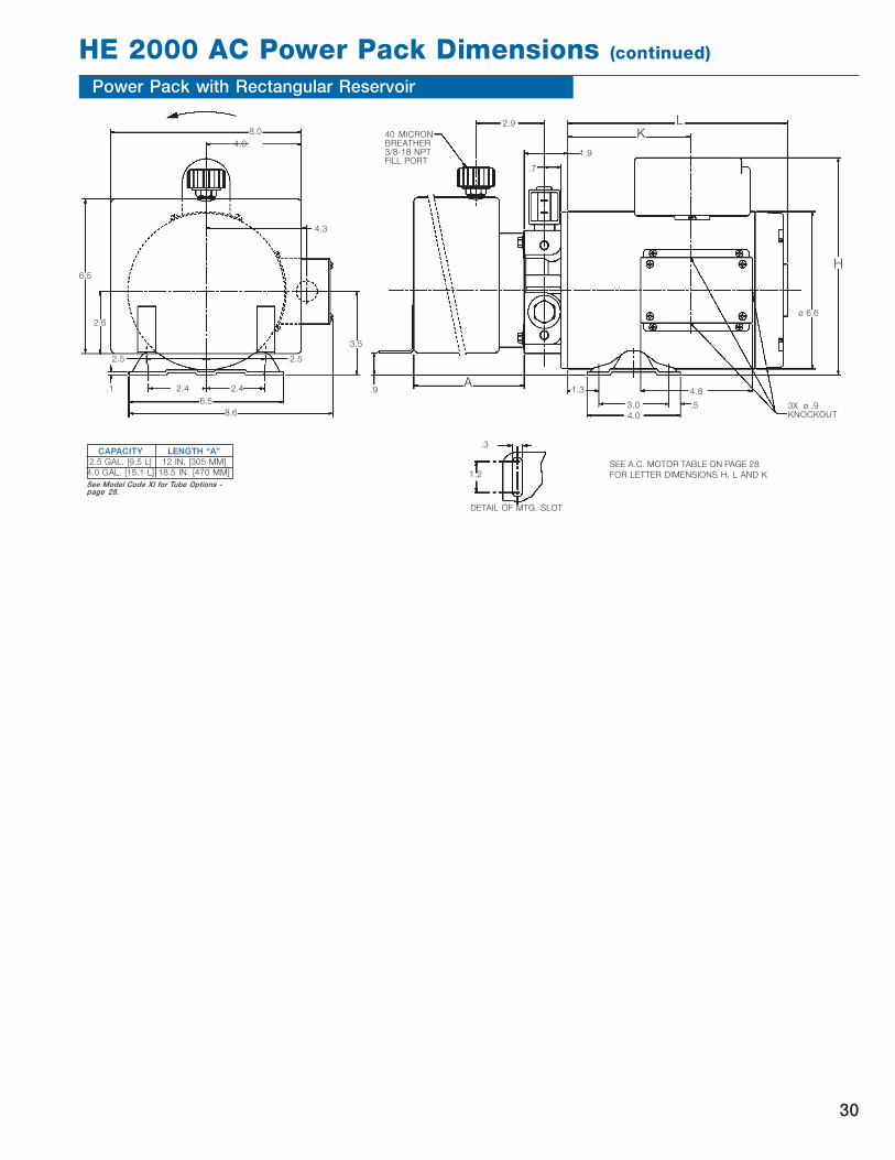
HE 2000 AC Power Pack Dimensions (continued)
Power Pack with Rectangular Reservoir
.3
1.2
DETAIL OF MTG. SLOT
3.5
H
L
K
1.9
.7
ø 6.6
.53.0
4.8
4.0
1.3
3X ø .9KNOCKOUT
A.9
40 MICRONBREATHER3/8-18 NPTFILL PORT
2.9
CAPACITY
2.5 GAL. [9.5 L]
4.0 GAL. [15.1 L]
LENGTH “A”
12 IN. [305 MM]
18.5 IN. [470 MM]SEE A.C. MOTOR TABLE ON PAGE 28
FOR LETTER DIMENSIONS H, L AND KSee Model Code XI for Tube Options -page 28.
8.0
4.0
4.3
2.52.5
.1
6.5
8.6
2.4 2.4
2.6
6.5
30

Cyl. down
Cyl. up
Symbols SI-units
Flow Q m3/s
Operating p Pa
pressure
Internal diameter, d m
hydraulic cylinder
Area of hydraulic A m2
cylinder
Piston force F N
Piston speed v m/s
Power requirement Pe kW
for AC motor
Equations
Q = 0,06 x v x A
Equations Common units
l/min
bar
mm
mm2
0,1 x Ap = F
4A = � x d2
Q = v x A
Ap = F
4A = � x d2
Pe = p x Q
Recomended viscosity 40-16mm2/s.
Permissible cold start viscosity is
2000mm2/s.
Contact factory before using fluids
outside this range.
Temperature min -25oC, max +80oC.
Fluid cleanliness We recommend a
cleanliness according to IS4406/1986
Code 18/14 or better to achieve optimal
performance and lifetime.
When operating outside these limits, see
recommendations in “Allowable fluids”.
Max pressure p1
230 bar
Intermittent p2
255 bar
Allowable fluids HL or HLP hydraulic
oils according to DIN 51524.
Biogradable fluids eg. Statoil Bio Pa.
Before using other types of fluids,
contact factory.
N
m/s
kW Pe =p x Q
611
31
HE 1000 Technical Information

Technical Information, Formulas and Symbols
Description
Flow
Operating Pressure
Internal diameter, hydraulic cylinder
Area of hydraulic cylinder
Piston force
Piston speed
Symbols
Q
p
d
A
F
v
English
Units Equations
gal/min Q = v x A
psi p = F
A
in
in2 A = ∏ x d2
4
LB F = p x A
in/s v = Q
A
Metric
Units Equations
l/min Q = 0.06 x v x A
bar p = F
0.1 x A
mm
mm2 A = ∏ x d2
4
N F = p x A x 0.1
m/s v = Q x 16.67
A
Supplemental Bolt Kits for Stock
Description Kit #Bolt Kit (AC Riser block + D03) 1300857Bolt Kit (AC Riser block + 2 - D03’s) 1300858Bolt Kit (AC Riser block + Manifold +D03) or (AC Riser block + 2 Manifolds)or (3 Manifolds) or (2 Manifolds + D03) 1300859Bolt Kit (Manifold) 1300860Bolt Kit (2 D03’s) 1300861Bolt Kit (3 D03’s) 1300862Bolt Kit (AC Riser block + Manifold) or (2 Manifolds) or (Manifold + D03) 1300863Bolt Kit (Manifold + 2 D03’s) 1300864Bolt Kit (D03) 1300865
HE 2000 Installation / Technical Information
FLUIDS
Most premium grade petroleum based
fluids can be used. Optimum operat-
ing viscosity range is 16 - 63 cSt (80 -
288 SSU).
Minimum recommended viscosity is
12 cSt (66 SSU).
Maximum recommended viscosity is
800 cSt (3600 SSU).
Permissable cold start viscosity is
2000 cSt (9000 SSU). Contact factory
before using fluids outside this range.
TEMPERATURES
Minimum recommended temperature
is -25ºC (-13ºF).
Maximum recommended temperature
is +80ºC (+175ºF).
FLUID CLEANLINESS
We recommend a cleanliness accord-
ing to IS4406/1986 Code 18/14 or
better to achieve optimal performance
and lifetime.
When operating outside these limits,
see recommendations in “FLUIDS”.
32

HE 2000 Extended Shaft DriveThe Extended Shaft Drive option allows for replacement of
the electric motor drive with a drive of the designer’s choice.
By allowing for drive shaft side loading with double ball
bearing support, the adapter may be used for pulley or belt
drives, direct engine drives, or fluid motor drives. In addi-
tion, the extended shaft adapter feature enables the de-
signer to adapt to larger electric motors, either DC or AC,
48 frame and larger. Installations of larger motors require a
flexible coupling and 4-hole flange adapter with a 1.780”
pilot hole and NEMA C face on the other end.
Specifications:
Maximum OHL at center of shaft extension 150 lbs.
Maximum inward thrust 75 lbs.
Maximum outward thrust 50 lbs.
Maximum speed 5000 RPM
Maximum input horsepower 3 HP
HE 2000 NEMA C AdapterThis adapter allows the HE2000 to mount on any Nema
56 frame motor with an AJ bolt mounting dimension of
5.88 inches; including 143T, 145T, 182, and 184.
The Nema C adapter is ideal for custom applications
requiring special AC or DC motor voltages.
“NEMA C” STYLE A.C. ELECTRIC MOTORFRAME SIZES 56, 143T, 145T, 182, 184 ANDANY OTHER WITH AN “AJ” DIMENSION OF5.88 INCHES.
2.25
ø 6.6
NOTE: Maximum torque rating of coupling connection to
pump tang is 10 ft.lbs.
NOTE: Contact factory for continuous pressures less
than 250 PSI.
33
1.312
9/16-18 SAERETURN PORT
1.78151.7800
#404 WOODRUFF KEY
.500
.5000
.4997
.557
2.00
1.00
.13.703
9/16-18 SAEOUTLET PORT
ADJUSTABLE RELIEFVALVE
.906
3.375
1.844
9/16-18 SAEAUX. OUTLET PORTNORMALLY PLUGGED
1.093
2.62
5/16-18 UNC-2BX .500 MIN. FULLTHREAD (3)
5/16-18 UNC-2BX .500 MIN. FULL THREAD (4)
MOUNTING HOLE OPTIONS
3/8-24 UNC-2B OR M10 X 1.5-6HX .500 MIN. FULL THREAD
2 MOUNTING HOLES PERMOUNTING PAD AT LOCATIONSSHOWN.
6.25-6.30
1.8751.875
2.62
1.875
1.875
1.000
1.000
1.000 1.000
3.37
CW ROTATION AS VIEWEDFROM SHAFT END
MOUNTING PAD “A”
MO
UN
TIN
G P
AD
“B
”
MOUNTINGHOLE
MOUNTINGHOLES
MOUNTINGHOLE
0
39
CONDUITBOX
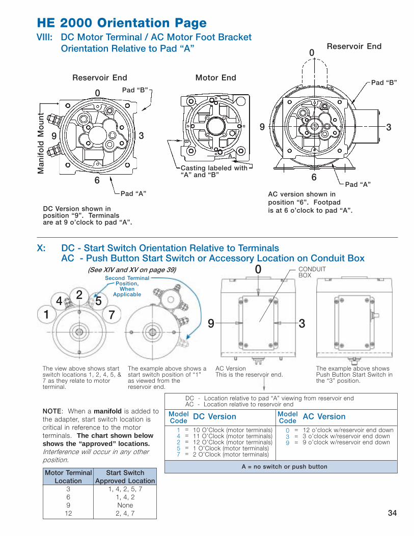
X: DC - Start Switch Orientation Relative to TerminalsAC - Push Button Start Switch or Accessory Location on Conduit Box
(See XIV and XV on page 39)
HE 2000 Orientation Page
VIII: DC Motor Terminal / AC Motor Foot Bracket
Orientation Relative to Pad “A” Reservoir End0
AC version shown in
position “6”. Footpad
is at 6 o’clock to pad “A”.DC Version shown inposition “9”. Terminalsare at 9 o’clock to pad “A”.
B
A
Motor End
Casting labeled with“A” and “B”
Reservoir End
Pad “B”
Pad “A”
0
6
39
Ma
nif
old
Mo
un
t
Pad “B”
Pad “A”6
39
The view above shows startswitch locations 1, 2, 4, 5, &7 as they relate to motorterminal.
The example above shows astart switch position of “1”as viewed from thereservoir end.
AC VersionThis is the reservoir end.
The example above showsPush Button Start Switch inthe “3” position.
NOTE: When a manifold is added to
the adapter, start switch location is
critical in reference to the motor
terminals. The chart shown belowshows the “approved” locations.Interference will occur in any other
position.
ModelCode
14257
DC Version
10 O’Clock (motor terminals)11 O’Clock (motor terminals)12 O’Clock (motor terminals)1 O’Clock (motor terminals)2 O’Clock (motor terminals)
A = no switch or push button
ModelCode
039
AC Version
12 o’clock w/reservoir end down3 o’clock w/reservoir end down9 o’clock w/reservoir end down
DC - Location relative to pad “A” viewing from reservoir endAC - Location relative to reservoir end
=====
===
Motor Terminal Start Switch
Location Approved Location
3 1, 4, 2, 5, 7
6 1, 4, 2
9 None
12 2, 4, 7 34
1
24 5
7
Second TerminalPosition,
WhenApplicable

Shown:
0 = 12 o’clock
to pad “A”
XII: Breather Orientation
Relative to Pad “A”
(Reservoir End View)
Orientation Page (cont.)
Pad “A”
0
6
39
Model Code0 = 12 o’clock3 = 3 o’clock6 = 6 o’clock9 = 9 o’clock
XIII: Coil Termination (Spade Terminal or Wire Leads)
Relative to Motor for Solenoid Acting Release
Valves
A
C
BD
Motor
Model CodeA = 12 o’clock = Toward MotorB = 3 o’clock = Away from CenterC = 6 o’clock = Toward ReservoirD = 9 o’clock = Toward CenterN = None
Note: The “Model Code” chart shown below applies to both“Coil Termination” and “Lever Orientation”. Either “Coil Termination”or “ Lever Orientation” must be selected for Option XIII, not both.
A C DB
Location relativeto motor viewingfrom top of coil ortop of manualrelease switch box
Release Pump
Pump
Release
Pump
ReleasePump Release
Lever
Lever
Lever
Lever
XIII: Lever Orientation Relative to Motor for
Manual Release Valves
Coil Spade
Terminals
The example above shows the coil spade terminalat the “B” position.
35
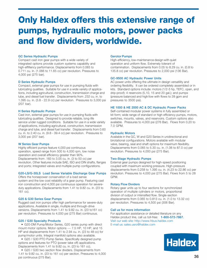
Only Haldex offers this extensive range of
pumps, hydraulic motors, power packs
and flow dividers, worldwide.
GC Series Hydraulic Pumps
Compact cast iron gear pumps with a wide variety of
integrated options provide custom systems capability and
high-effifiency performance. Displacements from 0.065 to
0.711 cu. in. (1.066 to 11.65 cc) per revolution. Pressures to
4,000 psi (275 bar).
D Series Hydraulic Pumps
Compact, external gear pumps for use in pumping fluids with
lubricating qualities. Suitable for use in a wide variety of applica-
tions, including agricultural, construction, transmission charge and
lube, and diesel fuel transfer. Displacements from .232 cu. in. to
1.395 cu. in. (3.8 - 22.9 cc) per revolution. Pressures to 3,000 psi
(207 bar).
H Series Hydraulic Pumps
Cast iron, external gear pumps for use in pumping fluids with
lubricating qualities. Designed to provide reliable, long-life
service under rugged conditions. Suitable for use in a wide variety
of applications, including agricultural, construction, transmission
charge and lube, and diesel fuel transfer. Displacements from 0.60
cu. in. to 2.40 cu. in. (9.8 - 39.4 cc) per revolution. Pressures to
3,000 psi (207 bar).
W Series Gear Pumps
Highly efficient pumps feature 4,000 psi continuous
operation, speed range from 500 to 4,000 rpm, low noise
operation and overall efficiency greater than 90%.
Displacements from .183 to 3.05 cu. in. (3 to 50 cc) per
revolution. Other features include SAE, ISO and DIN shafts, flanges
and ports; integrated valves and multiple pump configurations.
G20-LS/G-30LS Load Sense Variable Discharge Gear Pumps
Offers the horsepower conservation of a load sense
system and the low cost reliability of a gear pump. Featuring cast
iron construction and 4,000 psi continuous operation for severe-
duty applications. Displacements from 1.41 to 9.82 cu. in. (23 to
161 cc).
G20 & G30 Series Gear Pumps
Rugged cast iron pumps offer high performance for severe-duty
applications. Available in single, multiple and through-drive
versions. Displacements from 1.41 to 9.82 cu. in. (23 to161 cc)
per revolution. Pressures to 4,000 psi (275 Bar) continuous.
G20 / G30 Specialty Products
• G20-DM Pump/Motor Series, G20 series pump with direct
mount motor options. Motor options --- 7.5 HP, 10 HP, and 15
HP and displacements from 1.41 to 2.94 cu. in. (23 to 48 cc) for
pump/motor units. Integral manifold options also available.
• G20 / G30 PTO Pump Series. Specifically designed pump
options and features for PTO (power take off) applications.
Displacements from 1.41 to 9.82 cu. in. (23 to 161 cc).
• G20 / G30 two section flow dividers. Displacements from
1.41 to 9.82 cu. in. (23 to 161 cc) per section. Pressures to 4,000
psi continuous (275 Bar).
Gerotor Pumps
High-efficiency, low-maintenance design with quiet
operation and uniform flow. Extremely tolerant of
contamination. Displacements from 0.05 to 8.29 cu. in. (0.8 to
135.8 cc) per revolution. Pressures to 2,000 psi (136 Bar).
GC-9500 AC Hydraulic Power Units
AC power units offering the ultimate in design versatility and
ordering flexibility. It can be ordered completely assembled or in
kits. Standard options include: motors (1/2-5 hp, TEFC, open, and
drip-proof); 4 reservoirs (5,10, 15 and 20 gal.); and pumps
(pressure balanced and high/low with flows to 28 gpm and
pressures to 3500 psi).
HE 1000 & HE 2000 AC & DC Hydraulic Power Packs
Self-contained modular power systems in fully assembled or
kit form; wide range of standard or high efficiency pumps, motors,
switches, mounts, valves, and reservoirs. Custom options also
available. Pressures to 4,000 psi (276 Bar). Flows from 0.20 to
7.0 GPM.
Hydraulic Motors
Available in the GC, W and G20 Series in unidirectional and
birotational configurations. Motors available with modular
valve, bearing, seal and shaft options for maximum flexibility.
Displacements from 0.065 to 5.30 cu. in. (1.06 to 87.0 cc) per
revolution. Pressures to 4,000 psi (275 Bar).
Two-Stage Hydraulic Pumps
External gear pumps designed for high-speed positioning
coupled with maximum working pressure. High-pressure
displacements from 0.258 to 1.395 cu. in. (4.23 to 22.86 cc) per
revolution. Pressures to 4,000 psi (275 Bar). Flows from 5 to 28
GPM.
Rotary Flow Dividers
Rotary-gear units up to four sections for synchronized
operation of multiple cylinders or motors, proportional
division of output or intensified flow. Single-section
displacements from 0.065 to 0.813 cu. in. (1.0 to 13.32 cc)
per revolution. Pressures to 4,500 psi (306 Bar).
Call us for more information
For application assistance or detailed literature on any
Haldex product line, call us toll-free: 1-800-572-7867.
Visit our web site: http://www.hbus.haldex.com
E-mail us: [email protected]
36

HE 1000 Power Packs Order Code
To order a complete power pack, simply work through the options below, creating a model number as shown in the
example. All location positions are viewed from the reservoir end.
37
Example of Order Code Structure: HE1-NE024-05-150-C-15-AD-0-C-2-AA-0-A-00-00
Code HE 1000 Reservoir HE 1000 Kit No.AA .13 gal. (0.5 l) usable, horizontal, plastic 1303484AB .13 gal. (0.5 l) usable, vertical, plastic 1303485AC .26 gal. (1.0 l) usable, horizontal, plastic 1303486AD .26 gal. (1.0 l) usable, vertical, plastic 1303487AE .40 gal. (1.5 l) usable, horizontal, plastic 1303488AF .40 gal. (1.5 l) usable, vertical, plastic 1303489AG .53 gal. (2.0 l) usable, horizontal , plastic 1303490AH .53 gal. (2.0 l) usable, vertical, plastic 1303491AJ .66 gal. (2.5 l) usable, horizontal, plastic 1303492AK .66 gal. (2.5 l) usable, vertical, plastic 1303493AL 1.0 gal. (4.0 l) usable, horizontal, plastic 1303494AM 1.0 gal. (4.0 l) usable, vertical, plastic 1303495
Code HE 1000 Motor Terminal Position0 Terminals at 12 ó clock to pad "A"3 Terminals at 3 ó clock to pad "A"6 Terminals at 6 ó clock to pad "A"9 Terminals at 9 ó clock to pad "A"
Code HE 1000 Start Switch HE 1000 Kit No.A NoneB 12V, 4 Pole (2 Terminal Motors) 1300937C 24V, 4 Pole (2 Terminal Motors) 1300938D 12V, 3 Pole (1 Terminal Motor) 1300939
Code HE 1000 Start Switch Position2 12 o' clock to motor terminals1 10 o' clock to motor terminals4 11 o' clock to motor terminals5 1 o' clock to motor terminals7 2 o' clock to motor terminals
Code HE 1000 Tube KitAA Tube kit included in reservoir kit
Code HE 1000 Breather Position0 12 o' clock to pad "A"1 1:30 to pad "A"3 3 o' clock to pad "A"4 4:30 to pad "A"6 6 o' clock to pad "A"7 7:30 to pad "A"9 9 o' clock to pad "A"5 10:30 to pad "A"
Code HE 1000 Coil Terminals Position on Solenoid Valve(as viewed from side)
A 12 o' clock (towards motor)B 3 o' clock (towards reservoir)C 6 o' clock (towards pad "A")D 9 o' clock (away from pad "A")
Code HE 1000 Accessory 1 HE 1000 Kit No.00 No accessories26 Single Acting Pendant 1303569
Code HE 1000 Accessory 2 HE 1000 Kit No.00 No accessories10 Boots 1303554
Code HE 1000 Adaptor SizeHE 1 HE 1000 adaptor
HE 1000 Coil Voltage+ Valve Type HE 1000 Kit No.
NA000 Adaptor Kit for P & T Ports orBlock Mounted Valves 1303653
NE012 Valve Kit (12VDC Lift-Hold-LowerSolenoid Release Valve) 1300023
OrNE024 Valve Kit (24VDC Lift-Hold-Lower
Solenoid Release Valve) 1300024And Adaptor Kit (Lift-Hold-Lower Circuit) 1303654
NL012 2-Position, 4-Way Valve Kit w/12VDC Coil 1303655
OrNL024 2-Position, 4-Way Valve Kit
w/24VDC Coil 1303656And Adaptor Kit (2-Position, 4-Way Valve) 1303657
NO012 Valve Kit (12VDC Lift-Hold-Lower Solenoid Release Valve w/Manual Override) 1300783
OrNO024 Valve Kit (24VDC Lift-Hold-Lower Solenoid
Release Valve w/Manual Override) 1300784And Adaptor Kit (Lift-Hold-Lower Circuit) 1303654
Code HE 1000 Pump HE 1000 Kit No.02 0.015 in3 (0.24 cm3) 130343105 0.029 in3 (0.48 cm3) 130343208 0.051 in3 (0.84 cm3) 130343312 0.074 in3 (1.22 cm3) 130343415 0.100 in3 (1.50 cm3) 130358017 0.900 in3 (1.75 cm3) 130358120 0.122 in3 (2.00 cm3) 1303582
Code HE 1000 Relief Valve HE 1000 Kit No.*** Setting 50-250 bar, eg 150 bar 1303525
Code HE 1000 Flow Control Valve HE 1000 Kit No.A None C .53 gpm (2 l/min) 1303446D .79 gpm (3 l/min) 1303447E 1.0 gpm (4 l/min) 1303448F 1.3 gpm (5 l/min) 1303449
Code HE 1000 Motor HE 1000 Kit No.10 12 VDC, 2 Terminal, 3" Motor (80 mm) 130345415 24 VDC, 2 Terminal, 3" Motor (80 mm) 1303456
82 12 VDC, 2 Terminal, 4.5" Motor (112 mm)† 1300618
84 24 VDC, 2 Terminal, 4.5" Motor (112 mm)† 1300619
80 12 VDC, 1 Terminal, 4.5" Motor (112 mm)† 1300027
† Requires Motor Mounting Kit 1303658(Skanes #40599-00)

1234567890123456789012345678123456789012345678901234567812345678901234567890123456781234567890123456789012345678123456789012345678901234567812345678901234567890123456781234567890123456789012345678123456789012345678901234567812345678901234567890123456781234567890123456789012345678123456789012345678901234567812345678901234567890123456781234567890123456789012345678
123456789012345678901234567812345678901234567890123456781234567890123456789012345678123456789012345678901234567812345678901234567890123456781234567890123456789012345678
1234567890123456789012345678912345678901234567890123456789123456789012345678901234567891234567890123456789012345678912345678901234567890123456789
1234567890123456789012345678912345678901234567890123456789123456789012345678901234567891234567890123456789012345678912345678901234567890123456789
1234567890123456789012345678912345678901234567890123456789123456789012345678901234567891234567890123456789012345678912345678901234567890123456789
123456789012345678901234567812345678901234567890123456781234567890123456789012345678123456789012345678901234567812345678901234567890123456781234567890123456789012345678
123456789012345678901234567891234567890123456789012345678912345678901234567890123456789123456789012345678901234567891234567890123456789012345678912345678901234567890123456789123456789012345678901234567891234567890123456789012345678912345678901234567890123456789123456789012345678901234567891234567890123456789012345678912345678901234567890123456789123456789012345678901234567891234567890123456789012345678912345678901234567890123456789123456789012345678901234567891234567890123456789012345678912345678901234567890123456789123456789012345678901234567891234567890123456789012345678912345678901234567890123456789123456789012345678901234567891234567890123456789012345678912345678901234567890123456789123456789012345678901234567891234567890123456789012345678912345678901234567890123456789123456789012345678901234567891234567890123456789012345678912345678901234567890123456789123456789012345678901234567891234567890123456789012345678912345678901234567890123456789123456789012345678901234567891234567890123456789012345678912345678901234567890123456789
123456789012345678901234567891234567890123456789012345678912345678901234567890123456789123456789012345678901234567891234567890123456789012345678912345678901234567890123456789
12345678901234567890123456781234567890123456789012345678123456789012345678901234567812345678901234567890123456781234567890123456789012345678
123456789012345678901234567891234567890123456789012345678912345678901234567890123456789123456789012345678901234567891234567890123456789012345678912345678901234567890123456789
HE 2000 Power Packs Order Code
THE HE 2000 POWER PACK EXAMPLE SHOWN ABOVE consists of a 3-position / 4-way valve, dual pilot-operated check valves, a 2.6 cc/rev. pressure-balanced pump, a
12 volt two terminal DC motor with start switch, and a 1.3 quart plastic reservoir. The relief valve has been set at 150 BAR (2175 PSI) and the power pack has a 1 gallon
per minute (GPM) / 4 liter per minute (LPM) flow control valve incorporated into the return line circuit. The power pack is intended to be mounted in a vertical position
with the motor terminals and breather cap opposite to PAD A.
To order a complete power pack, simply work through the options below, creating a model number as shown in the example.
I II III IV V VI VII VIII IX X XI XII XIII XIV XV XVI
STANDARD POWER PACK
BR
EATH
ER
PO
SIT
ION
STA
RT S
WIT
CH
PO
SIT
ION
AD
AP
TO
R
OP
TIO
NS
PU
MP
TYP
E/S
IZE
RELIE
F V
ALVE
SE
TTIN
G
FLO
W C
ON
TR
OL
VA
LVE
MO
TO
R
RESER
VO
IR
MO
TO
RP
OS
ITIO
N
STA
RT S
WIT
CH
TU
BE K
IT
AD
AP
TER
SIZ
E
CO
IL / L
EVER
PO
SIT
ION
AC
CES
SO
RY
DES
IGN
SER
IES
AC
CES
SO
RY
EXAMPLE HE2 BH012 26 150 E 82 AF 6 H 2 KC 0 N 00 00 A3
Your Options HE2 *** DO NOT LEAVE ANY BLANK FIELDS *** A3
VI. MOTORKit #
54 EXTENDED SHAFT ADAPTER 130033555 AC FLANGE “NEMA C” ADAPTER 130354360 1/2 HP (30 min.), 3 PH, 50/60 Hz, 208-230/460 VAC, TENV,
1425/1725 130091662 1 HP (30 min.), 3 PH, 50/60 Hz, 208-230/460 VAC, TENV,
2850/3450 130091863 1 HP (30 min.), 3 PH, 50/60 Hz, 208-230/460 VAC, TEFC,
2850/3450 130091964 1 HP, 1 PH, 60 Hz, 115/208-230 VAC, TENV, 3450 130092065 1 HP, 1 PH, 50/60 Hz, 115/208-230 VAC, TEFC,
2850/3450 130092166 1 HP, 3 PH, 50/60 Hz, 208-230/460 VAC, TENV,
1425/1725 130092267 1 HP (30 min.), 1 PH, 60 Hz, 115/208-230 VAC, TENV, 1725 130092368 2 HP (30 min.), 1 PH, 60 Hz, 115/208-230 VAC, TENV, 3450 130092469 2 HP, 1 PH, 50/60 Hz, 115/208-230 VAC, TEFC, 2850/3450 130092570 2 HP (30 min.), 3 PH, 50/60 Hz, 208-230/460 VAC, TENV,
1425/1725 130092671 2 HP (30 min.), 1 PH, 60 Hz, 115/208-230 VAC, TENV, 1725 130092772 3 HP (30 min.), 3 PH, 50/60 Hz, 208-230/460 VAC, TENV,
2850/3450 130092873 3 HP, 3 PH, 50/60 Hz, 208-230/460 VAC, TEFC, 2850/3450 130092974 2.5 HP (30 min.), 1 PH, 50/60 Hz, 208-230 VAC, TENV,
2850/3450 130093080 12 VDC Single Term. - Standard Duty 130002782 12 VDC Double Term. - Medium Duty 130061883 24 VDC Single Term. - Medium Duty w/Ground Strap 130091284 24 VDC Double Term. - Medium Duty 130061985 24 VDC Double Term. - Med. Duty - Low Speed Compound 130091386 24 VDC Double Term. - Heavy Duty 1303551
V. FLOW CONTROL VALVEDescription Kit #
A None N/AE 4 LPM (1 GPM) 1303448K 8 LPM (2 GPM) 1303450M 10 LPM (2.5 GPM) 1303453N 11 LPM (3 GPM) 1303451R 15 LPM (4 GPM) 1303452
12345678901234567890123456781234567890123456789012345678123456789012345678901234567812345678901234567890123456781234567890123456789012345678123456789012345678901234567812345678901234567890123456781234567890123456789012345678123456789012345678901234567812345678901234567890123456781234567890123456789012345678
Pick a valve type and corresponding coil voltage, if applicable.
I. ADAPTER SIZE HE2 = HE 2000
III. PUMP TYPE/SIZE (/REV.)
Order Code Cm.3 In.3 Kit #
W Series Pumps
08 0.8 .049 1303435
12 1.2 .073 1303436
16 1.6 .098 1303437
20 2.0 .122 1303438
26 2.6 .153 1303439
32 3.2 .195 1303440
38 3.8 .232 1303441
43 4.3 .262 1303442
48 4.8 .293 1303443
57 5.7 .348 1303444
GC Series Pumps
70 1.06 .065 1300174
71 1.59 .097 1300176
72 2.12 .129 1300171
73 2.65 .162 1300625
74 3.18 .194 1300169
76 4.24 .259 1300172
77 5.30 .323 1300931
78 6.36 .388 1300932
MAX. PRESSURES
Continuous Intermittent
PSI BAR PSI BAR
3335 230 3698 255
3335 230 3698 255
3335 230 3698 255
3335 230 3698 255
3335 230 3698 255
3335 230 3698 255
3045 210 3335 230
2755 190 3045 210
2465 170 2712 187
2103 145 2320 160
PSI BAR PSI BAR
3000 207 4000 276
3000 207 4000 276
3000 207 4000 276
3000 207 4000 276
3000 207 4000 276
2300 159 4000 276
1900 131 3000 207
1600 110 2500 172
IV. RELIEF VALVE SETTINGS BAR SETTING RANGES Kit #
*** 014 - 033 BAR 1303659(200 - 500 PSI)034 - 103 BAR 1303660(501 - 1500 PSI)104 - 173 BAR 1303661(1501 - 2500 PSI)174 - 276 BAR 1303662(2501 - 4000 PSI)
Eg. 150 Bar (2175 PSI)
ADAPTER OPTIONS
II. VALVE KIT + COIL KITTYPE # VOLTAGE #
BA Adapter, P & T Ports, Adapter 1303649 BA000Relief Valve & Check Valve Port Plug 1300191
CA Adapter, P & T Ports, Adapter 1303649 CA000Relief Valve & Check Valve Port Plug 1300191
AC Motor Adapter 1303549BB Solenoid Lowering Adapter Adapter 1303649 BB012* 12 Volt DC 1300914
Solenoid Release Valve 1303534 BB024* 24 Volt DC 1300915CB Solenoid Lowering Adapter Adapter 1303649 CB115* 115 Volt AC 1303576
Solenoid Release Valve 1303534 CB230* 230 Volt AC 1303577AC Motor Adapter 1303549 CB012* 12 Volt DC 1300914
CB024* 24 Volt DC 1300915BE Manual Lowering Adapter 1303649 BE000
Adapter w/DC Contactor Manual Release Valve 1300192w/Pilot Contactor
CE AC Manual Lowering Adapter 1303649 CE000Valve Adapter Manual Release Valve 1303533
AC Motor Adapter 1303549Motor Spool (DC Version, AC Version and DC Version w/Double P.O. Check)BF Manifold Adapter w/3-Pos. Adapter 1303650 BF012+ 12 Volt DC 1300914
4-Way Valve (Motor Spool) Manifold 1300866 BF024+ 24 Volt DC 1300915DC Version Motor Spool Valve 1303382
Cavity Plug 1303540BH Manifold Adapter w/3-Pos. Adapter 1303650 BH012+ 12 Volt DC 1300914
4-Way Valve (Motor Spool) Manifold 1300866 BH024+ 24 Volt DC 1300915DC Version w/Double P.O. Motor Spool Valve 1303382
Double P.O.Check 1303538CF Manifold Adapter w/3-Pos. Adapter 1303650 CF115+ 115 Volt AC 1303576
4-Way Valve (Motor Spool) Manifold 1300866 CF230+ 230 Volt AC 1303577AC Version Motor Spool Valve 1303382 CF012+ 12 Volt DC 1300914
Cavity Plug 1303540 CF024+ 24 Volt DC 1300915Riser Block 1300855AC Motor Adapter 1303549
Tandem Center Spool (DC and AC Versions)BJ Manifold Adapter w/3-Pos. Adapter 1303650 BJ012+ 12 Volt DC 1300914
4-Way Valve (Tandem Center Manifold 1300856 BJ024+ 24 Volt DC 1300915Spool) DC Version Tandem Center Valve 1303530
Cavity Plug 1303540CJ Manifold Adapter w/3-Pos. Adapter 1303650 CJ115+ 115 Volt AC 1303576
4-Way Valve (Tandem Center Manifold 1300856 CJ230+ 230 Volt AC 1303577Spool) AC Version Tandem Center Valve 1303530 CJ012+ 12 Volt DC 1300914
Cavity Plug 1303540 CJ024+ 24 Volt DC 1300915Riser Block 1300855AC Motor Adapter 1303549
Solenoid Operated, 2-Position, 4-Way Normally Open Valve (DC and AC Versions)BR Manifold Adapter w/Sol. Adapter 1303650 BR012* 12 Volt DC 1300914
Operated, 2-Pos., 4-Way Manifold 1300856 BR024* 24 Volt DC 1300915Valve DC Version Normally Open Valve 1303529
Cavity Plug 1303540CR Manifold Adapter w/Sol. Adapter 1303650 CR115* 115 Volt AC 1303576
Operated, 2-Pos., 4-Way Manifold 1300856 CR230* 230 Volt AC 1303577Valve AC Version Normally Open Valve 1303529 CR012* 12 Volt DC 1300914
Cavity Plug 1303540 CR024* 24 Volt DC 1300915Riser Block 1300855AC Motor Adapter 1303549
BS Manifold Adapter w/Sol. Adapter 1303650 BS012* 12 Volt DC 1300914Operated, 2-Pos., 4-Way Manifold 1300856 BS024* 24 Volt DC 1300915Valve DC Version w/P.O. Normally Open Valve 1303529Check Single P.O. Check 1303539
Single D03 Valve Manifold (DC and AC Versions) / Double D03 Valve Manifold (AC Version Only)DA Manifold Adapter w/ Adapter 1303650 DA000
Single D03 Valve Manifold D03 Manifold 1300854DC Version Bolts 1300865
DB Manifold Adapter w/ Adapter 1303650 DB000Single D03 Valve Manifold D03 Manifold 1300854AC Version Bolts 1300857
Riser Block 1300855AC Motor Adapter 1303549
DC Manifold Adapter w/ Adapter 1303650 DC000Double D03 Valve Manifold D03 1300854AC Version Only Manifolds (2) (2)
Bolts 1300858Riser Block 1300855AC Motor Adapter 1303549
DM Manifold Adapter (DC Version) Adapter 1303650 DM000AM Manifold Adapter (AC Version) Adapter 1303650 AM000
AC Motor Adapter 1303549* Quantity of 1 needed. + Quantity of 2 needed.NOTE: AC coils have 36 inch cables. All DC coils have dual spades.
HE 2000 Power Packs Order Code (continued)
XVI. DESIGN SERIESA Major Change to form, fit or function3 Minor Design Change
Note: Design Series is assigned by the factoryat the current level.
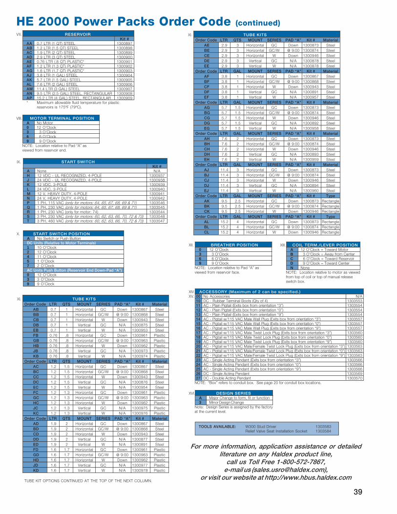
XIII. COIL TERM./LEVER POSITIONA 12 O’Clock = Toward MotorB 3 O’Clock = Away from CenterC 6 O’Clock = Toward ReservoirD 9 O’Clock = Toward CenterN None
NOTE: Location relative to motor as viewedfrom top of coil or top of manual releaseswitch box.
XII. BREATHER POSITION0 12 O’Clock3 3 O’Clock6 6 O’Clock9 9 O’Clock
NOTE: Location relative to Pad “A” asviewed from reservoir face.
For more information, application assistance or detailed
literature on any Haldex product line,
call us Toll Free 1-800-572-7867,
e-mail us ([email protected]),
or visit our website at http://www.hbus.haldex.com
XIV. ACCESSORY (Maximum of 2 can be specified.)XV. 00 No Accessories N/A
10 DC - Rubber Terminal Boots (Qty of 4) 130355311 AC - Plain Pigtail (Exits box from orientation “3”) 130355412 AC - Plain Pigtail (Exits box from orientation “0”) 130355413 AC - Plain Pigtail (Exits box from orientation “9”) 130355414 AC - Pigtail w/115 VAC Male Wall Plug (Exits box from orientation “3”) 130355715 AC - Pigtail w/115 VAC Male Wall Plug (Exits box from orientation “0”) 130355716 AC - Pigtail w/115 VAC Male Wall Plug (Exits box from orientation “9”) 130355717 AC - Pigtail w/115 VAC Male Twist Lock Plug (Exits box from orientation “3”) 130356018 AC - Pigtail w/115 VAC Male Twist Lock Plug (Exits box from orientation “0”) 130356019 AC - Pigtail w/115 VAC Male Twist Lock Plug (Exits box from orientation “9”) 130356020 AC - Pigtail w/115 VAC Male/Female Twist Lock Plug (Exits box from orientation “3”) 130356321 AC - Pigtail w/115 VAC Male/Female Twist Lock Plug (Exits box from orientation “0”) 130356322 AC - Pigtail w/115 VAC Male/Female Twist Lock Plug (Exits box from orientation “9”) 130356323 AC - Single Acting Pendant (Exits box from orientation “3”) 130356624 AC - Single Acting Pendant (Exits box from orientation “0”) 130356625 AC - Single Acting Pendant (Exits box from orientation “9”) 130356626 DC - Single Acting Pendant 130356927 DC - Double Acting Pendant 1303570
NOTE: “Box” refers to conduit box. See page 20 for conduit box locations.
XI. TUBE KITS
Order Code LTR QTS MOUNT SERIES PAD “A” Kit # Material
AB 0.7 1 Horizontal GC Down 1300867 Steel
BB 0.7 1 Horizontal GC/W @ 9:00 1300868 Steel
CB 0.7 1 Horizontal W Down 1300943 Steel
DB 0.7 1 Vertical GC N/A 1300875 Steel
EB 0.7 1 Vertical W N/A 1300953 Steel
FB 0.76 .8 Horizontal GC Down 1300961 Plastic
GB 0.76 .8 Horizontal GC/W @ 9:00 1300963 Plastic
HB 0.76 .8 Horizontal W Down 1300962 Plastic
JB 0.76 .8 Vertical GC N/A 1300973 Plastic
KB 0.76 .8 Vertical W N/A 1300974 Plastic
Order Code LTR QTS MOUNT SERIES PAD “A” Kit # Material
AC 1.2 1.5 Horizontal GC Down 1300867 Steel
BC 1.2 1.5 Horizontal GC/W @ 9:00 1300868 Steel
CC 1.2 1.5 Horizontal W Down 1300943 Steel
DC 1.2 1.5 Vertical GC N/A 1300876 Steel
EC 1.2 1.5 Vertical W N/A 1300954 Steel
FC 1.2 1.3 Horizontal GC Down 1300961 Plastic
GC 1.2 1.3 Horizontal GC/W @ 9:00 1300963 Plastic
HC 1.2 1.3 Horizontal W Down 1300962 Plastic
JC 1.2 1.3 Vertical GC N/A 1300975 Plastic
KC 1.2 1.3 Vertical W N/A 1300976 Plastic
Order Code LTR QTS MOUNT SERIES PAD “A” Kit # Material
AD 1.9 2 Horizontal GC Down 1300867 Steel
BD 1.9 2 Horizontal GC/W @ 9:00 1300868 Steel
CD 1.9 2 Horizontal W Down 1300943 Steel
DD 1.9 2 Vertical GC N/A 1300877 Steel
ED 1.9 2 Vertical W N/A 1300891 Steel
FD 1.6 1.7 Horizontal GC Down 1300961 Plastic
GD 1.6 1.7 Horizontal GC/W @ 9:00 1300963 Plastic
HD 1.6 1.7 Horizontal W Down 1300962 Plastic
JD 1.6 1.7 Vertical GC N/A 1300977 Plastic
KD 1.6 1.7 Vertical W N/A 1300978 Plastic
TUBE KIT OPTIONS CONTINUED AT THE TOP OF THE NEXT COLUMN.
XI. TUBE KITS
Order Code LTR QTS MOUNT SERIES PAD “A” Kit # Material
AE 2.9 3 Horizontal GC Down 1300873 Steel
BE 2.9 3 Horizontal GC/W @ 9:00 1300874 Steel
CE 2.9 3 Horizontal W Down 1300946 Steel
DE 2.9 3 Vertical GC N/A 1300878 Steel
EE 2.9 3 Vertical W N/A 1300878 Steel
Order Code LTR GAL MOUNT SERIES PAD “A” Kit # Material
AF 3.8 1 Horizontal GC Down 1300867 Steel
BF 3.8 1 Horizontal GC/W @ 9:00 1300868 Steel
CF 3.8 1 Horizontal W Down 1300943 Steel
DF 3.8 1 Vertical GC N/A 1300891 Steel
EF 3.8 1 Vertical W N/A 1300957 Steel
Order Code LTR GAL MOUNT SERIES PAD “A” Kit # Material
AG 5.7 1.5 Horizontal GC Down 1300873 Steel
BG 5.7 1.5 Horizontal GC/W @ 9:00 1300874 Steel
CG 5.7 1.5 Horizontal W Down 1300946 Steel
DG 5.7 1.5 Vertical GC N/A 1300892 Steel
EG 5.7 1.5 Vertical W N/A 1300958 Steel
Order Code LTR GAL MOUNT SERIES PAD “A” Kit # Material
AH 7.6 2 Horizontal GC Down 1300873 Steel
BH 7.6 2 Horizontal GC/W @ 9:00 1300874 Steel
CH 7.6 2 Horizontal W Down 1300946 Steel
DH 7.6 2 Vertical GC N/A 1300893 Steel
EH 7.6 2 Vertical W N/A 1300959 Steel
Order Code LTR GAL MOUNT SERIES PAD “A” Kit # Material
AJ 11.4 3 Horizontal GC Down 1300873 Steel
BJ 11.4 3 Horizontal GC/W @ 9:00 1300874 Steel
CJ 11.4 3 Horizontal W Down 1300946 Steel
DJ 11.4 3 Vertical GC N/A 1300894 Steel
EJ 11.4 3 Vertical W N/A 1300960 Steel
Order Code LTR GAL MOUNT SERIES PAD “A” Kit # Type
AK 9.5 2.5 Horizontal GC Down 1300873 Rectangle
BK 9.5 2.5 Horizontal GC/W @ 9:00 1300874 Rectangle
CK 9.5 2.5 Horizontal W Down 1300946 Rectangle
Order Code LTR GAL MOUNT SERIES PAD “A” Kit # Type
AL 15.2 4 Horizontal GC Down 1300873 Rectangle
BL 15.2 4 Horizontal GC/W @ 9:00 1300874 Rectangle
CL 15.2 4 Horizontal W Down 1300946 Rectangle
VIII. MOTOR TERMINAL POSITIONA No Motor0 12 O’Clock3 3 O’Clock6 6 O’Clock9 9 O’Clock
NOTE: Location relative to Pad “A” asviewed from reservoir end.
IX. START SWITCHKit #
A None N/AH 12 VDC - UL RECOGNIZED, 4-POLE 1300937J 24 VDC - UL RECOGNIZED, 4-POLE 1300938K 12 VDC, 3-POLE 1300939L 24 VDC, 3-POLE 1300940M 12 V, HEAVY DUTY, 4-POLE 1300941N 24 V, HEAVY DUTY, 4-POLE 1300942P 1 PH, 115 VAC (only for motors: 64, 65, 67, 68, 69 & 71) 1303546Q 1 PH, 230 VAC (only for motors: 64, 65, 67, 68, 69 & 71) 1303545R 1 PH, 230 VAC (only for motor: 74) 1303544S 3 PH, 230 VAC (only for motors: 60, 62, 63, 66, 70, 72 & 73) 1303548T 3 PH, 460 VAC (only for motors: 60, 62, 63, 66, 70, 72 & 73) 1303547
VII. RESERVOIRKit #
AA 0.7 LTR (1 QT) STEEL 1300897AB 1.2 LTR (1.5 QT) STEEL 1300898AC 1.9 LTR (2 QT) STEEL 1300899AD 2.9 LTR (3 QT) STEEL 1300900AE 0.76 LTR (.8 QT) PLASTIC* 1300901AF 1.2 LTR (1.3 QT) PLASTIC* 1300902AG 1.6 LTR (1.7 QT) PLASTIC* 1300903AJ 3.8 LTR (1 GAL) STEEL 1300904AK 5.7 LTR (1.5 GAL) STEEL 1300905AL 7.6 LTR (2 GAL) STEEL 1300906AM 11.4 LTR (3 GAL) STEEL 1300907AN 9.5 LTR (2.5 GAL) STEEL, RECTANGULAR 1300908AP 15.2 LTR (4 GAL) STEEL, RECTANGULAR 1300909* Maximum allowable fluid temperature for plastic
reservoirs is 175ºF (79ºC).
X. START SWITCH POSITIONA No Switch or Push ButtonDC Units (Relative to Motor Terminals)1 10 O’Clock2 12 O’Clock4 11 O’Clock5 1 O’Clock7 2 O’ClockAC Units Push Button (Reservoir End Down-Pad “A”)0 12 O’Clock3 3 O’Clock9 9 O’Clock
TOOLS AVAILABLE: W300 Stud Driver 1303583Relief Valve Seat Installation Socket 1303584
39
www.hbus.haldex.com
Haldex Hydraulics Corp.
2222 15th StreetROCKFORD, IL 61104USATel: +1-815 398 4400Fax: +1-815 398 5977E-mail: [email protected]
Haldex Hydraulics Corp.
214 James Farm RoadSTATESVILLE, NC 28625USATel: +1-704 873 2587Fax: +1-704 878 0530E-mail: [email protected]
Haldex Hydraulics AB
Box 95SE-280 40 SK. FAGERHULTSwedenTel: +46-433 32400Fax: +46-433 30546E-mail: [email protected]
Haldex Hydraulics AB
Box 511SE-195 25 MÄRSTASwedenTel: +46–8 591 288 50Fax: +46-8 591 288 60E-mail: [email protected]
Haldex Hydraulics GmbH
Postfach 1507D-95014 HOFGermanyTel: +49-9281 895-0Fax: +49-9281 87133E-mail: [email protected]
Haldex is an
innovator in
vehicle technology
supplying proprietary systems and
components for trucks, cars and
industrial vehicles, worldwide. With
4,100 employees and yearly sales
exceeding 7 bil l ion Swedish
Kronor, Haldex is listed on the
Stockholm Stock Exchange
(www.haldex.com).
PRODUCT RANGE
He Power Packs
12/24/48 VDC 0.8 – 3.5 kW and
0.75 – 3 kW AC modular power
packs
Pressure Switches
5 - 350 bar, connecting/
disconnecting
He Classic Power Packs
12/24/48 VDC modular
powerpacks in weatherproof
boxes
W300 Hydraulic pumps
0.8 – 5.7 cc 230 bar
W600 Hydraulic pumps
4 – 12 cc/section 276 bar
WM600 Hydraulic motors
4 – 12 cc/section 276 bar
W900 Hydraulic pumps
5 – 31 cc/section 276 bar
WM900 Hydraulic motors
5 - 31 cc/section 276 bar
WQ900 The quiet pump
5 - 23 cc/section 230 bar
W1500 Hydraulic pumps
19 - 50 cc/section 276 bar
WM1500 Hydraulic motors
19 - 50 cc/section 276 bar
G25 Hydraulic pumps
23 – 87 cc/section 250 bar
GM25 Hydraulic motors
23 – 87 cc/section 250 bar
GPA Internal Gear pumps
1.7 – 63 cc/section 100 bar
GC Hydraulic pumps / fluid motors
1.06 – 11.65 cc/section 276 bar
II-Stage Hydraulic pumps
4.2 – 22.8 cc/section 276 bar
Rotary Flow Dividers
3.8 – 13.3 cc/section 300 bar
D Hydraulic pumps
3.8 - 22.9 cc/section 207 bar
H Hydraulic pumps
9.8 - 39.4 cc/section 207 bar
G20/G30 Hydraulic pumps
23 – 161 cc/section 276 bar
GM20/GM30 Hydraulic motors
23 – 161 cc/section 276 bar
G20/G30 (LS) Hydraulic pumps
23 – 161 cc/section 276 bar
Transmission pumps
Fuel pumps
HE PWR PK 12 / 02
The right to modification for technical improvements is reserved. Printed in USA.