heat transfer and flow on the blade tip of a gas turbine ...heat transfer for various blade tip...
TRANSCRIPT
A.A. AmeriAYT Corporation, Brook Park, Ohio
Heat Transfer and Flow on the Blade Tipof a Gas Turbine Equipped With aMean-Camberline Strip
NASA/CR—2001-210764
May 2001
2001–GT–0156

The NASA STI Program Office . . . in Profile
Since its founding, NASA has been dedicated tothe advancement of aeronautics and spacescience. The NASA Scientific and TechnicalInformation (STI) Program Office plays a key partin helping NASA maintain this important role.
The NASA STI Program Office is operated byLangley Research Center, the Lead Center forNASA’s scientific and technical information. TheNASA STI Program Office provides access to theNASA STI Database, the largest collection ofaeronautical and space science STI in the world.The Program Office is also NASA’s institutionalmechanism for disseminating the results of itsresearch and development activities. These resultsare published by NASA in the NASA STI ReportSeries, which includes the following report types:
• TECHNICAL PUBLICATION. Reports ofcompleted research or a major significantphase of research that present the results ofNASA programs and include extensive dataor theoretical analysis. Includes compilationsof significant scientific and technical data andinformation deemed to be of continuingreference value. NASA’s counterpart of peer-reviewed formal professional papers buthas less stringent limitations on manuscriptlength and extent of graphic presentations.
• TECHNICAL MEMORANDUM. Scientificand technical findings that are preliminary orof specialized interest, e.g., quick releasereports, working papers, and bibliographiesthat contain minimal annotation. Does notcontain extensive analysis.
• CONTRACTOR REPORT. Scientific andtechnical findings by NASA-sponsoredcontractors and grantees.
• CONFERENCE PUBLICATION. Collectedpapers from scientific and technicalconferences, symposia, seminars, or othermeetings sponsored or cosponsored byNASA.
• SPECIAL PUBLICATION. Scientific,technical, or historical information fromNASA programs, projects, and missions,often concerned with subjects havingsubstantial public interest.
• TECHNICAL TRANSLATION. English-language translations of foreign scientificand technical material pertinent to NASA’smission.
Specialized services that complement the STIProgram Office’s diverse offerings includecreating custom thesauri, building customizeddata bases, organizing and publishing researchresults . . . even providing videos.
For more information about the NASA STIProgram Office, see the following:
• Access the NASA STI Program Home Pageat http://www.sti.nasa.gov
• E-mail your question via the Internet [email protected]
• Fax your question to the NASA AccessHelp Desk at 301–621–0134
• Telephone the NASA Access Help Desk at301–621–0390
• Write to: NASA Access Help Desk NASA Center for AeroSpace Information 7121 Standard Drive Hanover, MD 21076

NASA/CR—2001-210764
May 2001
National Aeronautics andSpace Administration
Glenn Research Center
Prepared under Contract NAS3–00180
Prepared for the2001 Summer Annual Gas Turbine Conferencesponsored by the American Society of Mechanical EngineersNew Orleans, Louisiana, June 3–7, 2001
A.A. AmeriAYT Corporation, Brook Park, Ohio
Heat Transfer and Flow on the Blade Tipof a Gas Turbine Equipped With aMean-Camberline Strip
2001–GT–0156

Acknowledgments
This work was sponsored by the Turbomachinery and Combustion Technology Project. The author wishes toexpress his gratitude to Dr. Raymond Gaugler, Chief of the Turbine Branch, for his support and encourage-
ment of this work and Dr. R.S. Bunker for sharing of the experimental data and figures. Thanks are alsodue to my colleague Dr. Erlendur Steinthorsson for his reading and criticism of the manuscript. Some
of the computations were performed on the CRAY–C90 of NAS at NASA Ames Research Center.
Available from
NASA Center for Aerospace Information7121 Standard DriveHanover, MD 21076
National Technical Information Service5285 Port Royal RoadSpringfield, VA 22100
Available electronically at http://gltrs.grc.nasa.gov/GLTRS

11
ABSTRACTExperimental and computational studies have been
performed to investigate the detailed distribution of convectiveheat transfer coefficients on the first-stage blade tip surface for ageometry typical of large power generation turbines(>100MW).In a previous work the numerical heat transfer results for asharp edge blade tip and a radiused blade tip were presented.More recently several other tip treatments have been consideredfor which the tip heat transfer has been measured anddocumented. This paper is concerned with the numericalprediction of the tip surface heat transfer for radiused blade tipequipped with mean-camberline strip (or “squealer” as it isoften called). The heat transfer results are compared with theexperimental results and discussed. The effectiveness of themean-camberline strip in reducing the tip leakage and the tipheat transfer as compared to a radiused edge tip and sharp edgetip was studied. The calculations show that the sharp edge tipworks best (among the cases considered) in reducing the tipleakage flow and the tip heat transfer.
NOMENCLATURECp constant pressure specific heat
h heat transfer coefficient
Pr Prandtl number
R gas constant
Re Reynolds number
T static temperature/
Tu turbulence intensity
V magnitude of the velocity/(R T0)1/2
dimensionless distance from a wall,
specific heat ratioτ shear stress
T0
y+
y+
yτw ρ⁄
ν-----------------=
γ
Y Total pressure loss,
Subscripts
t total conditions
w wall value
0 inlet condition
1 exit conditions
INTRODUCTIONBlade tips are susceptible to burnout and oxidation due to
high thermal loading caused by the tip leakage flow. Efficientinternal or film cooling schemes are necessary to protect turbineblades against damage. The design of such schemes requiresdetailed knowledge of heating patterns on and near the tips whichcould be gained by experimental and predictive methods. It wasshown by Mayle and Metzger [1] that the heat transfer at a bladetip (and by extension total pressure loss) is not very much affectedby rotation. This has spurred experimental work on measuring tipheat transfer for various blade tip treatments on stationarycascades and has provided data for numerical simulations. In aprevious numerical study [2] the predicted tip heat transfer for asharp edge tip and a radiused tip (blade tip with a rounded edgearound the perimeter of the blade tip) was compared with themeasured experimental data of Bunker et al. [3]. The data was, atthe time, the only set of liquid crystal measurements of tip heattransfer. The results of simulations nicely agreed with theexperimental data and showed that the tip heat transfer forradiused edge would be larger than that for a sharp edge tip due tothe relatively higher velocity on the radiused edge tip than on thesharp edge tip. More recently, Bunker and Bailey [4] have madefurther measurements for various tip treatments includingcircumferential rub strip, 45-degree angled run strips, perimetersquealer rim and mean-camberline strip.
Pt0Pt1
–
Pt0P1–
-------------------
Heat Transfer and Flow on the Blade Tip of a Gas Turbine Equipped with a Mean-CamberlineStrip
A. A. Ameri AYT Corporation
Brook Park, Ohio [email protected]
NASA/CR—2001-210764

2
The perimeter squealer tip case has already been computedby Ameri et al. [5] though for a different blade configuration. Inthis paper the mean-camberline strip (squealer) case has beencomputed. The computed tip heat transfer has been comparedwith experimental measurements. As the experiment was mainlyconcerned with the measurement of the rate of heat transfer, thenumerical simulation attempts to construct the flow structure inorder to help explain the phenomena observed in theexperiments.
In the ensuing section a brief description of the experimentsimulated in this work is provided. The numerical methodemployed and the grid topology used to model thecomputational domain are described subsequently. The resultsof the simulations showing the flow characteristics andcomputed tip leakage rate as well as the tip heat transfer are nextpresented and are followed by a summary and presentation ofthe conclusions of the work.
THE EXPERIMENTAL SETUPThe experimental setup and conditions are similar to those
described in [3]. In that paper the pressure distribution and tipheat transfer for both a sharp edge tip and radiused edge tip ofthe present blade geometry were presented. The heat transfermeasurement considered in this paper is for the same radiusededge blade in [3] but is equipped with a mean-camberline stripas given in Bunker and Bailey[4].
Figure 1 shows the definition of the airfoils and the shroud.The blade profiles are typical of a large power generation
13.37 cm
44.9¡
65.75¡
5.19 cm
12.45 cm
Tip2 mm
3.43 cm Shroud
LE TE
Fig. 1Airfoil and shroud definition
TurbulenceGrid
CompressorAir
Test Section
51-cm diameterVessel
SplashPlate
RectangularInlet Duct
TurbulenceBars
ExhaustDuct
splitter plate turbulence bars
turbulence grids
casing recessFig. 2Experimental rig
TABLE 1: Run Conditions
Pressure ratio across the blade row 0.69
Exit Reynolds number 2.57E6
Inlet Mach number 0.30
Turbulence intensity 5%
Inlet angle 44.9 deg.
turbine. The cascade is linear and the span is 10.16cm. As can beseen the shroud incorporates a recess ahead of the blades to modela similar feature found in an actual turbine shroud. Theinstrumented blade has a rounded edge of 2.54-mm radius. The tipclearance addressed in this paper is the nominal value of 2.03 mmmeasured from the top surface of the mean-camberline strip. Theheight of the mean-camberline strip was 1.27 mm. This places theblade tip surface at 3.30 mm from the shroud (In [3] this distancewas 2.03 mm). The strip in the experiment and in the calculationshas a square cross section and sharp edges. Figure 2 shows thedesign of the actual two passage blade cascade as reproducedfrom Bunker et al. [3]. The extent of the strip is from the leadingedge to 85% axial chord. Table 1 lists the run conditions for thecascade and input to the numerical simulations.
THE COMPUTATIONAL METHODThe simulations in this study were performed using a multi-
block computer code called Glenn-HT [6] which is based on asingle block code designed by Arnone et al. [7]. This code is ageneral purpose flow solver designed for simulations of flows incomplicated geometries. The code solves the full compressible,Reynolds-averaged Navier-Stokes equations using a multi-stageRunge-Kutta based multigrid method. It uses the finite volumemethod to discretize the equations. The code uses centraldifferencing together with artificial dissipation to discretize theconvective terms. The overall accuracy of the code is secondorder. The present version of the code [5,8,9] employs the k-ωturbulence model developed by Wilcox[10,11] with modifications
NASA/CR—2001-210764

3
(b)(b)
Oct 10 16:22 2000 • Program Development Corporation • (914) 761-9152
(e)
Oct 10 16:22 2000 • Program Development Corporation • (914) 761-9152
(d)
(a)
Oct 10 14:29 2000 • Program Development Corporation • (914) 761-9152
(c)
Y
X
Z
Tip with Camber-Line Strip
Frame 001 1 May 2000 Frame 001 1 May 2000
(a)
of the flow. The main differences between the present simulationand the actual geometry are twofold: The mean-camberline in theexperiment is made up of piecewise straight lines and starts rightat the leading edge whereas in the CFD simulation the strip isplaced as a continuous strip and starts at a location 5% of axialchord and not from the leading edge. This was done for practicalgrid generation reasons. The grid is generated using acommercially available computer program called GridProTM. Themodel of Fig. 3 consisted of 1.2 million cells when a a sharp edgetip was used. The number of cells were 1.4 million for thegeometry with the radiused edge smooth tip. For the present caseof a blade with a mean-camberline strip 1.8 million cells wereused. The viscous grid is generated by embedding grid lineswhere needed, including the grid around the splitter. Thestretching ratio did not exceed 1.25 for the viscous grid awayfrom the no-slip surfaces. The distance to the first cell centeradjacent to solid wall is such that the distance in wall units, (y+) isnear or below unity. Specifically in the tip region the number ofgrid cells from the tip of the strip to the shroud was 50 and from
Fig. 3Blade tip/passage and grid construction
by Menter [12]. The model integrates to the walls and no wallfunctions are used. For heat transfer a constant value of 0.9 forturbulent Prandtl number,Prt and a value for Prandtl number(Pr) equal to 0.72 is used. Viscosity is a function of temperaturethrough a 0.7 power law [13]and is taken to be a constant.
GEOMETRY MODELING AND GRID SYSTEM
As in [2] the complete two blade passage was modeled.This was done to achieve better agreement with the measuredpressure distribution on the tip in the cited work. Figure 3(a)shows the blade surface and the modeled mean-camberline strip.Figure 3(b) (reproduced from [2]) shows the grid for thecomplete passage including the splitter plate. Figure 3(c) showsthe surface grid on the blade tip with the radiused edge and themean- camberline strip. The grid details on the tip including themean-camberline strip is shown in figure 3(d). 3(e) showsfurther the details of the grid around the strip. The topology isdesigned such that the viscous gridlines stay near the surfaces(including the strip) and do not spread in the “inviscid” regions
Cp
NASA/CR—2001-210764

44
the tip surface to the shroud was 58 cells. Further details aboutthe grid may be found in [2].
RESULTS AND DISCUSSIONAlong with the conditions given in Table 1, a very thin
boundary layer thickness of 0.1% of the passage height wasimposed at the inlet to the computational domain upstream of theflow splitter (at the location of upstream turbulence grid in Fig.2). The tunnel side walls were modeled using a slip boundarycondition [2].
Figure 4 shows the streamline patterns of the flow in the tipclearance. Due to the rounded edge of the tip, the flow has littledifficulty negotiating the turn into the clearance passage. Incontrast on a sharp edge tip, a separation vortex forms along thepressure side edge of the blade tip thus narrowing the passageand thereby reducing the leakage[2]. Figure 4(b) shows thestreamline pattern with the strip present. A separation vortexpattern behind the strip can be discerned from that figure. Figure5 shows the pressure distribution over the blade tip. Note that theareas of low pressure are associated with high velocities. In Fig.6, the velocity vectors over the blade tip for several axial crosssections (Fig. 6(a)) and a plane parallel to tip at the half height of
Fig. 4Streamline patterns of the flow in the tip region for(a) radius edged tip (b) radius edged tip and meancamber
line strip
(b)(a)
(b)
(a)
Fig. 6Velocity vectors colored by the velocity magnitude|V|.
Fig. 5Pressure distribution (P static/P0) over the blade tipsurface
(b)
NASA/CR—2001-210764
55
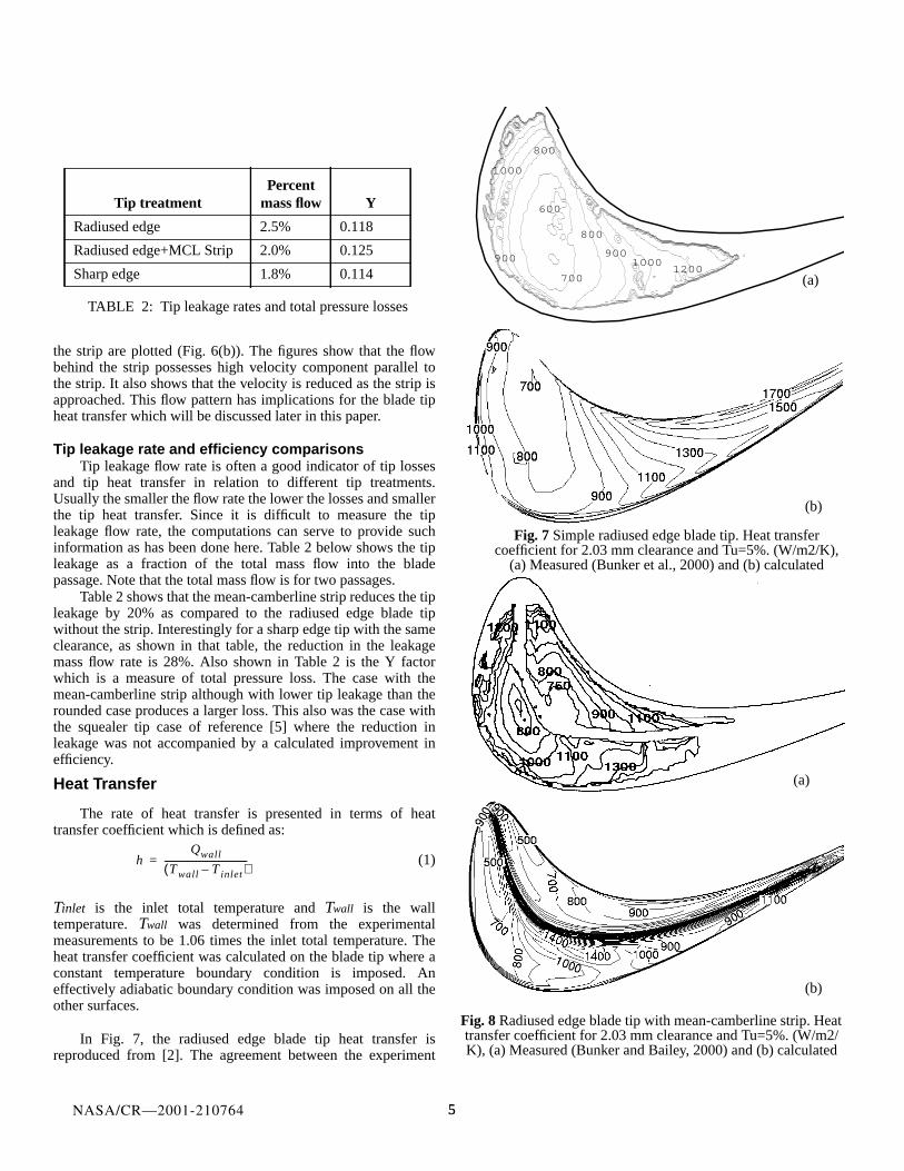
the strip are plotted (Fig. 6(b)). The figures show that the flowbehind the strip possesses high velocity component parallel tothe strip. It also shows that the velocity is reduced as the strip isapproached. This flow pattern has implications for the blade tipheat transfer which will be discussed later in this paper.
Tip leakage rate and efficiency comparisonsTip leakage flow rate is often a good indicator of tip losses
and tip heat transfer in relation to different tip treatments.Usually the smaller the flow rate the lower the losses and smallerthe tip heat transfer. Since it is difficult to measure the tipleakage flow rate, the computations can serve to provide suchinformation as has been done here. Table 2 below shows the tipleakage as a fraction of the total mass flow into the bladepassage. Note that the total mass flow is for two passages.
Table 2 shows that the mean-camberline strip reduces the tipleakage by 20% as compared to the radiused edge blade tipwithout the strip. Interestingly for a sharp edge tip with the sameclearance, as shown in that table, the reduction in the leakagemass flow rate is 28%. Also shown in Table 2 is the Y factorwhich is a measure of total pressure loss. The case with themean-camberline strip although with lower tip leakage than therounded case produces a larger loss. This also was the case withthe squealer tip case of reference [5] where the reduction inleakage was not accompanied by a calculated improvement inefficiency.
Heat Transfer
The rate of heat transfer is presented in terms of heattransfer coefficient which is defined as:
(1)
Tinlet is the inlet total temperature andTwall is the walltemperature.Twall was determined from the experimentalmeasurements to be 1.06 times the inlet total temperature. Theheat transfer coefficient was calculated on the blade tip where aconstant temperature boundary condition is imposed. Aneffectively adiabatic boundary condition was imposed on all theother surfaces.
In Fig. 7, the radiused edge blade tip heat transfer isreproduced from [2]. The agreement between the experiment
hQwall
T wall T inlet–( )-------------------------------------=
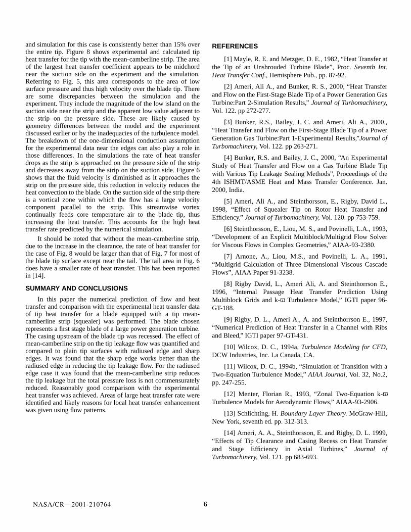
Fig. 8 Radiused edge blade tip with mean-camberline strip. Heattransfer coefficient for 2.03 mm clearance and Tu=5%. (W/m2/K), (a) Measured (Bunker and Bailey, 2000) and (b) calculated
900
1000
800
12001000
900
800
700
600
(a)
(3D) 26 Jan 1999
800
900
700
900
1100
1300
15001700
1000
1100
(3D) 26 Jan 1999
(b)
(b)
(a)
Fig. 7Simple radiused edge blade tip. Heat transfercoefficient for 2.03 mm clearance and Tu=5%. (W/m2/K),
(a) Measured (Bunker et al., 2000) and (b) calculated
(b)
Tip treatmentPercent
mass flow Y
Radiused edge 2.5% 0.118
Radiused edge+MCL Strip 2.0% 0.125
Sharp edge 1.8% 0.114
TABLE 2: Tip leakage rates and total pressure losses
NASA/CR—2001-210764
66
and simulation for this case is consistently better than 15% overthe entire tip. Figure 8 shows experimental and calculated tipheat transfer for the tip with the mean-camberline strip. The areaof the largest heat transfer coefficient appears to be midchordnear the suction side on the experiment and the simulation.Referring to Fig. 5, this area corresponds to the area of lowsurface pressure and thus high velocity over the blade tip. Thereare some discrepancies between the simulation and theexperiment. They include the magnitude of the low island on thesuction side near the strip and the apparent low value adjacent tothe strip on the pressure side. These are likely caused bygeometry differences between the model and the experimentdiscussed earlier or by the inadequacies of the turbulence model.The breakdown of the one-dimensional conduction assumptionfor the experimental data near the edges can also play a role inthose differences. In the simulations the rate of heat transferdrops as the strip is approached on the pressure side of the stripand decreases away from the strip on the suction side. Figure 6shows that the fluid velocity is diminished as it approaches thestrip on the pressure side, this reduction in velocity reduces theheat convection to the blade. On the suction side of the strip thereis a vortical zone within which the flow has a large velocitycomponent parallel to the strip. This streamwise vortexcontinually feeds core temperature air to the blade tip, thusincreasing the heat transfer. This accounts for the high heattransfer rate predicted by the numerical simulation.
It should be noted that without the mean-camberline strip,due to the increase in the clearance, the rate of heat transfer forthe case of Fig. 8 would be larger than that of Fig. 7 for most ofthe blade tip surface except near the tail. The tail area in Fig. 6does have a smaller rate of heat transfer. This has been reportedin [14].
SUMMARY AND CONCLUSIONS
In this paper the numerical prediction of flow and heattransfer and comparison with the experimental heat transfer dataof tip heat transfer for a blade equipped with a tip mean-camberline strip (squealer) was performed. The blade chosenrepresents a first stage blade of a large power generation turbine.The casing upstream of the blade tip was recessed. The effect ofmean-camberline strip on the tip leakage flow was quantified andcompared to plain tip surfaces with radiused edge and sharpedges. It was found that the sharp edge works better than theradiused edge in reducing the tip leakage flow. For the radiusededge case it was found that the mean-camberline strip reducesthe tip leakage but the total pressure loss is not commensuratelyreduced. Reasonably good comparison with the experimentalheat transfer was achieved. Areas of large heat transfer rate wereidentified and likely reasons for local heat transfer enhancementwas given using flow patterns.
REFERENCES
[1] Mayle, R. E. and Metzger, D. E., 1982, “Heat Transfer atthe Tip of an Unshrouded Turbine Blade”, Proc.Seventh Int.Heat Transfer Conf., Hemisphere Pub., pp. 87-92.
[2] Ameri, Ali A., and Bunker, R. S., 2000, “Heat Transferand Flow on the First-Stage Blade Tip of a Power Generation GasTurbine:Part 2-Simulation Results,”Journal of Turbomachinery,Vol. 122. pp 272-277.
[3] Bunker, R.S., Bailey, J. C. and Ameri, Ali A., 2000.,“Heat Transfer and Flow on the First-Stage Blade Tip of a PowerGeneration Gas Turbine:Part 1-Experimental Results,”Journal ofTurbomachinery, Vol. 122. pp 263-271.
[4] Bunker, R.S. and Bailey, J. C., 2000, “An ExperimentalStudy of Heat Transfer and Flow on a Gas Turbine Blade Tipwith Various Tip Leakage Sealing Methods”, Proceedings of the4th ISHMT/ASME Heat and Mass Transfer Conference. Jan.2000, India.
[5] Ameri, Ali A., and Steinthorsson, E., Rigby, David L.,1998, “Effect of Squealer Tip on Rotor Heat Transfer andEfficiency,” Journal of Turbomachinery, Vol. 120. pp 753-759.
[6] Steinthorsson, E., Liou, M. S., and Povinelli, L.A., 1993,“Development of an Explicit Multiblock/Multigrid Flow Solverfor Viscous Flows in Complex Geometries,” AIAA-93-2380.
[7] Arnone, A., Liou, M.S., and Povinelli, L. A., 1991,“Multigrid Calculation of Three Dimensional Viscous CascadeFlows”, AIAA Paper 91-3238.
[8] Rigby David, L., Ameri Ali, A. and Steinthorrson E.,1996, “Internal Passage Heat Transfer Prediction UsingMultiblock Grids and k-ω Turbulence Model,” IGTI paper 96-GT-188.
[9] Rigby, D. L., Ameri A., A. and Steinthorrson E., 1997,“Numerical Prediction of Heat Transfer in a Channel with Ribsand Bleed,” IGTI paper 97-GT-431.
[10] Wilcox, D. C., 1994a,Turbulence Modeling for CFD,DCW Industries, Inc. La Canada, CA.
[11] Wilcox, D. C., 1994b, “Simulation of Transition with aTwo-Equation Turbulence Model,”AIAA Journal, Vol. 32, No.2,pp. 247-255.
[12] Menter, Florian R., 1993, “Zonal Two-Equation k-ωTurbulence Models for Aerodynamic Flows,” AIAA-93-2906.
[13] Schlichting, H.Boundary Layer Theory. McGraw-Hill,New York, seventh ed. pp. 312-313.
[14] Ameri, A. A., Steinthorsson, E. and Rigby, D. L. 1999,“Effects of Tip Clearance and Casing Recess on Heat Transferand Stage Efficiency in Axial Turbines,”Journal ofTurbomachinery, Vol. 121. pp 683-693.
NASA/CR—2001-210764
This publication is available from the NASA Center for AeroSpace Information, 301–621–0390.
REPORT DOCUMENTATION PAGE
2. REPORT DATE
19. SECURITY CLASSIFICATION OF ABSTRACT
18. SECURITY CLASSIFICATION OF THIS PAGE
Public reporting burden for this collection of information is estimated to average 1 hour per response, including the time for reviewing instructions, searching existing data sources,gathering and maintaining the data needed, and completing and reviewing the collection of information. Send comments regarding this burden estimate or any other aspect of thiscollection of information, including suggestions for reducing this burden, to Washington Headquarters Services, Directorate for Information Operations and Reports, 1215 JeffersonDavis Highway, Suite 1204, Arlington, VA 22202-4302, and to the Office of Management and Budget, Paperwork Reduction Project (0704-0188), Washington, DC 20503.
NSN 7540-01-280-5500 Standard Form 298 (Rev. 2-89)Prescribed by ANSI Std. Z39-18298-102
Form Approved
OMB No. 0704-0188
12b. DISTRIBUTION CODE
8. PERFORMING ORGANIZATION REPORT NUMBER
5. FUNDING NUMBERS
3. REPORT TYPE AND DATES COVERED
4. TITLE AND SUBTITLE
6. AUTHOR(S)
7. PERFORMING ORGANIZATION NAME(S) AND ADDRESS(ES)
11. SUPPLEMENTARY NOTES
12a. DISTRIBUTION/AVAILABILITY STATEMENT
13. ABSTRACT (Maximum 200 words)
14. SUBJECT TERMS
17. SECURITY CLASSIFICATION OF REPORT
16. PRICE CODE
15. NUMBER OF PAGES
20. LIMITATION OF ABSTRACT
Unclassified Unclassified
Final Contractor Report
Unclassified
1. AGENCY USE ONLY (Leave blank)
10. SPONSORING/MONITORING AGENCY REPORT NUMBER
9. SPONSORING/MONITORING AGENCY NAME(S) AND ADDRESS(ES)
National Aeronautics and Space AdministrationWashington, DC 20546–0001
Available electronically at http://gltrs.grc.nasa.gov/GLTRS
May 2001
NASA CR—2001-2107642001–GT–0156
E–12693
WU–714–03–50–00NAS3–00180
12
Heat Transfer and Flow on the Blade Tip of a Gas Turbine EquippedWith a Mean-Camberline Strip
A.A. Ameri
Turbomachinery; Gas turbine; Turbine heat transfer; Modeling; Blade Tip
Unclassified -UnlimitedSubject Categories: 02 and 34 Distribution: Nonstandard
AYT Corporation2001 Aerospace ParkwayBrook Park, Ohio 44142
Prepared for the 2001 Summer Annual Gas Turbine Conference sponsored by the American Society of MechanicalEngineers, New Orleans, Louisiana, June 3–7, 2001. Project Manager, R. Gaugler, Turbomachinery and PropulsionSystems Division, NASA Glenn Research Center, organization code 5820, 216–433–5882.
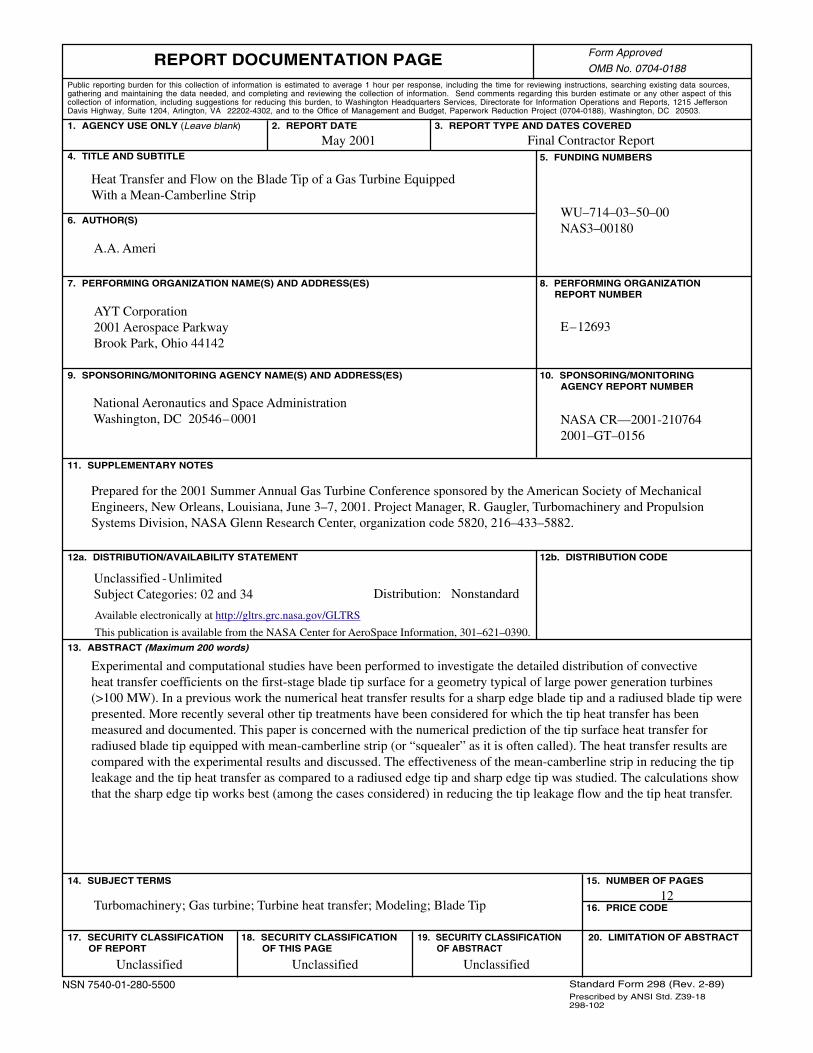
Experimental and computational studies have been performed to investigate the detailed distribution of convectiveheat transfer coefficients on the first-stage blade tip surface for a geometry typical of large power generation turbines(>100 MW). In a previous work the numerical heat transfer results for a sharp edge blade tip and a radiused blade tip werepresented. More recently several other tip treatments have been considered for which the tip heat transfer has beenmeasured and documented. This paper is concerned with the numerical prediction of the tip surface heat transfer forradiused blade tip equipped with mean-camberline strip (or “squealer” as it is often called). The heat transfer results arecompared with the experimental results and discussed. The effectiveness of the mean-camberline strip in reducing the tipleakage and the tip heat transfer as compared to a radiused edge tip and sharp edge tip was studied. The calculations showthat the sharp edge tip works best (among the cases considered) in reducing the tip leakage flow and the tip heat transfer.