heavy duty orbital motors technical information -...
TRANSCRIPT

Technical Information
Orbital MotorsHeavy Duty
powersolutions.danfoss.com

Revision history Table of revisions
Date Changed Rev
Dec 2017 Update WS shaft drawing 0201
Mar 2017 First edition 0101
Technical InformationHeavy Duty Orbital Motors
2 | © Danfoss | Dec 2017 BC00000386en-US0201

Technical InformationOperating Recommendations..................................................................................................................................................... 4
Oil Type........................................................................................................................................................................................... 4Fluid Viscosity and Filtration...................................................................................................................................................4Installation and Start-up...........................................................................................................................................................4Motor Protection......................................................................................................................................................................... 4Hydraulic Motor Safety Precaution.......................................................................................................................................4Motor/Brake Precaution........................................................................................................................................................... 5
Motor Connections.......................................................................................................................................................................... 6Product Testing................................................................................................................................................................................. 7Allowable Bearing and Shaft Loading.......................................................................................................................................7Vehicle Drive Calculations.............................................................................................................................................................9Induced Side Load......................................................................................................................................................................... 12Hydraulic Equations...................................................................................................................................................................... 13Shaft Nut Information...................................................................................................................................................................14
Optional Motor FeaturesSpeed Sensor Options..................................................................................................................................................................16Freeturning Rotor Option........................................................................................................................................................... 19Internal Drain...................................................................................................................................................................................19Valve Cavity Option.......................................................................................................................................................................20Slinger Seal Option........................................................................................................................................................................21
WS SeriesWS 360 Series Product Line Introduction..............................................................................................................................22WS 360 Series Displacement Performance...........................................................................................................................23WS 360 Series...................................................................................................................................................................................28
WS 360 Series Housings......................................................................................................................................................... 28WS 360 Series Technical Information................................................................................................................................ 31WS 360 Series Porting Options............................................................................................................................................ 35WS 360 Series Shafts................................................................................................................................................................35WS 360 Series Short Motor Information...........................................................................................................................39WS 360 Series Ultra Short Motor Information................................................................................................................ 41WS 360 Series Ordering Information................................................................................................................................. 44
Technical InformationHeavy Duty Orbital Motors
Contents
© Danfoss | Dec 2017 BC00000386en-US0201 | 3

Operating Recommendations
Oil Type
Hydraulic oils with anti-wear, anti-foam and demulsifiers are recommended for systems incorporatingDanfoss motors. Straight oils can be used but may require VI (viscosity index) improvers depending onthe operating temperature range of the system. Other water based and environmentally friendly oils maybe used, but service life of the motor and other components in the system may be significantlyshortened. Before using any type of fluid, consult the fluid requirements for all components in the systemfor compatibility. Testing under actual operating conditions is the only way to determine if acceptableservice life will be achieved.
Fluid Viscosity and Filtration
Fluids with a viscosity between 20 - 43 cSt [100 - 200 S.U.S.] at operating temperature is recommended.Fluid temperature should also be maintained below 85°C [180° F]. It is also suggested that the type ofpump and its operating specifications be taken into account when choosing a fluid for the system. Fluidswith high viscosity can cause cavitation at the inlet side of the pump. Systems that operate over a widerange of temperatures may require viscosity improvers to provide acceptable fluid performance.
Danfoss recommends maintaining an oil cleanliness level of ISO 17-14 or better.
Installation and Start-up
When installing a Danfoss motor it is important that the mounting flange of the motor makes full contactwith the mounting surface of the application. Mounting hardware of the appropriate grade and size mustbe used. Hubs, pulleys, sprockets and couplings must be properly aligned to avoid inducing excessivethrust or radial loads. Although the output device must fit the shaft snug, a hammer should never beused to install any type of output device onto the shaft. The port plugs should only be removed from themotor when the system connections are ready to be made. To avoid contamination, remove all matterfrom around the ports of the motor and the threads of the fittings. Once all system connections aremade, it is recommended that the motor be run-in for 15-30 minutes at no load and half speed to removeair from the hydraulic system.
Motor Protection
Over-pressurization of a motor is one of the primary causes of motor failure. To prevent these situations,it is necessary to provide adequate relief protection for a motor based on the pressure ratings for thatparticular model. For systems that may experience overrunning conditions, special precautions must betaken. In an overrunning condition, the motor functions as a pump and attempts to convert kineticenergy into hydraulic energy. Unless the system is properly configured for this condition, damage to themotor or system can occur.
To protect against this condition a counterbalance valve or relief cartridge must be incorporated into thecircuit to reduce the risk of overpressurization. If a relief cartridge is used, it must be installed upline ofthe motor, if not in the motor, to relieve the pressure created by the over-running motor. To provideproper motor protection for an over-running load application, the pressure setting of the pressure reliefvalve must not exceed the intermittent rating of the motor.
Hydraulic Motor Safety Precaution
A hydraulic motor must not be used to hold a suspended load. Due to the necessary internal tolerances,all hydraulic motors will experience some degree of creep when a load induced torque is applied to amotor at rest. All applications that require a load to be held must use some form of mechanical brakedesigned for that purpose.
Technical InformationHeavy Duty Orbital Motors
Technical Information
4 | © Danfoss | Dec 2017 BC00000386en-US0201

Motor/Brake Precaution
C Caution
Danfoss’ motors/brakes are intended to operate as static or parking brakes. System circuitry must bedesigned to bring the load to a stop before applying the brake.
C Caution
Because it is possible for some large displacement motors to overpower the brake, it is critical that themaximum system pressure be limited for these applications. Failure to do so could cause serious injury ordeath. When choosing a motor/brake for an application, consult the performance chart for the series anddisplacement chosen for the application to verify that the maximum operating pressure of the systemwill not allow the motor to produce more torque than the maximum rating of the brake. Also, it is vitalthat the system relief be set low enough to insure that the motor is not able to overpower the brake.
To ensure proper operation of the brake, a separate case drain back to tank must be used. Use of theinternal drain option is not recommended due to the possibility of return line pressure spikes. A simpleschematic of a system utilizing a motor/brake is shown in Typical Motor/Brake Schematic on page 5.Although maximum brake release pressure may be used for an application, a 34 bar [500 psi] pressurereducing valve is recommended to promote maximum life for the brake release piston seals. However, ifa pressure reducing valve is used in a system which has case drain back pressure, the pressure reducingvalve should be set to 34 bar [500 psi] over the expected case pressure to ensure full brake release.
To achieve proper brake release operation, it is necessary to bleed out any trapped air and fill brakerelease cavity and hoses before all connections are tightened. To facilitate this operation, all motor/brakes feature two release ports. One or both of these ports may be used to release the brake in the unit.Motor/brakes should be configured so that the release ports are near the top of the unit in the installedposition.
Typical Motor/Brake Schematic
P109317
Technical InformationHeavy Duty Orbital Motors
Technical Information
© Danfoss | Dec 2017 BC00000386en-US0201 | 5

Once all system connections are made, one release port must be opened to atmosphere and the brakerelease line carefully charged with fluid until all air is removed from the line and motor/brake releasecavity. When this has been accomplished the port plug or secondary release line must be reinstalled. Inthe event of a pump or battery failure, an external pressure source may be connected to the brake releaseport to release the brake, allowing the machine to be moved.
W Warning
It is vital that all operating recommendations be followed. Failure to do so could result in injury or death.
Motor Connections
There are two common types of circuits used for connecting multiple numbers of motors – seriesconnection and parallel connection.
Series Connection
When motors are connected in series, the outlet of one motor is connected to the inlet of the next motor.This allows the full pump flow to go through each motor and provide maximum speed. Pressure andtorque are distributed between the motors based on the load each motor is subjected to. The maximumsystem pressure must be no greater than the maximum inlet pressure of the first motor. The allowableback pressure rating for a motor must also be considered. In some series circuits the motors must have anexternal case drain connected. A series connection is desirable when it is important for all the motors torun the same speed such as on a long line conveyor.
Series Circuit
P109318
Parallel Connection
In a parallel connection all of the motor inlets are connected. This makes the maximum system pressureavailable to each motor allowing each motor to produce full torque at that pressure. The pump flow issplit between the individual motors according to their loads and displacements. If one motor has no load,the oil will take the path of least resistance and all the flow will go to that one motor. The others will notturn. If this condition can occur, a flow divider is recommended to distribute the oil and act as adifferential.
Parallel Circuit
P109319
The motor circuits shown above are for illustration purposes only. Components and circuitry for actualapplications may vary greatly and should be chosen based on the application.
Technical InformationHeavy Duty Orbital Motors
Technical Information
6 | © Danfoss | Dec 2017 BC00000386en-US0201

Product Testing
Performance testing is the critical measure of a motor’s ability to convert flow and pressure into speedand torque. All product testing is conducted using Danfoss’ state of the art test facility. This facility utilizesfully automated test equipment and custom designed software to provide accurate, reliable test data.Test routines are standardized, including test stand calibration and stabilization of fluid temperature andviscosity, to provide consistent data. The example below provides an explanation of the values pertainingto each heading on the performance chart.
25
50
100
200
301
401
24
50
100
200
300
400
502
602
690
21
43
99
199
297
398
500
601
689
18
43
92
191
295
390
499
600
688
17
34
87
181
284
384
498
597
658
11
32
79
174
271
372
485
540
644
11
32
78
160
253
346
443
526
631
9
31
77
154
245
339
433
510
613
[127]
[140]
[139]
[127]
[113]
[91]
14
16
16
14
13
10
[262]
[286]
[280]
[275]
[262]
[243]
[212]
[177]
[127]
30
32
32
31
30
27
24
20
14
[543]
[559]
[563]
[572]
[557]
[536]
[511]
[482]
[445]
61
63
64
65
63
61
58
54
50
[806]
[839]
[857]
[872]
[853]
[826]
[790]
[767]
[741]
91
95
97
99
96
93
89
87
84
[1062]
[1099]
[1139]
[1155]
[1149]
[1125]
[1087]
[1060]
[1098]
120
124
129
131
130
127
123
120
124
[1285]
[1340]
[1390]
[1420]
[1420]
[1409]
[1379]
[1451]
[1369]
145
151
157
160
160
159
156
164
155
[1496]
[1579]
[1652]
[1643]
[1646]
[1654]
[1638]
[1711]
[1640]
169
178
187
186
186
187
185
193
185
[1693]
[1796]
[1865]
[1911]
[1930]
[1945]
[1883]
[2021]
[1918]
191
203
211
216
218
220
213
228
217
Flow
- lp
m [g
pm]
17 [250] 35 [500] 69 [1000] 104 [1500] 138 [2000] 173 [2500] 207 [3000] 242 [3500]
Pressure - bars [psi]
21 [183] 41 [366] 83 [732] 124 [1099] 166 [1465] 207 [1831] 248 [2197] 290 [2564]
Theoretical Torque - Nm [lb-in]
Max
.In
ter.
Max
.C
ont.
76 cc [4.6 in3/rev.]
080
2 [0.5]
4 [1]
8 [2]
15 [4]
23 [6]
30 [8]
38 [10]
45 [12]
53 [14]
61 [16]
64 [17]
26
51
101
201
302
402
503
603
704
804
904
Theoretical rpm
Overall Efficiency - 70 - 100% 40 - 69% 0 - 39%
Intermittent Ratings - 10% of Operation
Displacement tested at 54°C [129°F] with an oil viscosity of 46cSt [213 SUS]
Max. Inter.Max. Cont.
1
2
34
5
8
7
Torque - Nm [lb-in], Speed rpm6
P109395
1. Flow represents the amount of fluid passing throughthe motor during each minute of the test.
2. Pressure refers to the measured pressure differentialbetween the inlet and return ports of the motor duringthe test.
3. The maximum continuous pressure rating andmaximum intermittent pressure rating of the motor areseparated by the dark lines on the chart.
4. Theoretical RPM represents the RPM that the motorwould produce if it were 100% volumetrically efficient.Measured RPM divided by the theoretical RPM give theactual volumetric efficiency of the motor.
5. The maximum continuous flow rating and maximumintermittent flow rating of the motor are separated by thedark line on the chart.
6. Performance numbers represent the actual torque andspeed generated by the motor based on thecorresponding input pressure and flow. The numbers onthe top row indicate torque as measured in Nm [lb-in],while the bottom number represents the speed of theoutput shaft.
7. Areas within the white shading represent maximummotor efficiencies.
8. Theoretical Torque represents the torque that themotor would produce if it were 100% mechanicallyefficient. Actual torque divided by the theoretical torquegives the actual mechanical efficiency of the motor.
Allowable Bearing and Shaft Loading
This catalog provides curves showing allowable radial loads at points along the longitudinal axis of themotor. They are dimensioned from the mounting flange. Two capacity curves for the shaft and bearingsare shown. A vertical line through the centerline of the load drawn to intersect the x-axis intersects thecurves at the load capacity of the shaft and of the bearing.
Technical InformationHeavy Duty Orbital Motors
Technical Information
© Danfoss | Dec 2017 BC00000386en-US0201 | 7

In the example below the maximum radial load bearing rating is between the internal roller bearingsillustrated with a solid line. The allowable shaft rating is shown with a dotted line.
The bearing curves for each model are based on labratory analysis and testing results constructed atDanfoss. The shaft loading is based on a 3:1 safety factor and 330 Kpsi tensile strength. The allowableload is the lower of the curves at a given point. For instance, one inch in front of the mounting flange thebearing capacity is lower than the shaft capacity. In this case, the bearing is the limiting load. The motoruser needs to determine which series of motor to use based on their application knowledge.
ISO 281 Ratings vs. Manufacturer's Ratings
Published bearing curves can come from more than one type of analysis. The ISO 281 bearing rating is aninternational standard for the dynamic load rating of roller bearings. The rating is for a set load at a speedof 33 1/3 RPM for 500 hours (1 million revolutions). The standard was established to allow consistentcomparisons of similar bearings between manufacturers. The ISO 281 bearing ratings are based solely onthe physical characteristics of the bearings, removing any manufacturers specific safety factors orempirical data that influences the ratings.
Manufacturers’ ratings are adjusted by diverse and systematic laboratory investigations, checkedconstantly with feedback from practical experience. Factors taken into account that affect bearing life arematerial, lubrication, cleanliness of the lubrication, speed, temperature, magnitude of the load and thebearing type.
The operating life of a bearing is the actual life achieved by the bearing and can be significantly differentfrom the calculated life. Comparison with similar applications is the most accurate method for bearing lifeestimations.
9000
8000
7000
6000
5000
4000
3000
2000
1000lb
4000
3500
3000
2500
2000
1500
1000
500daN
445 daN [1000 lb]
445 daN [1000 lb]
BEARING
SHAFT
-100 -50 -25 0 25 50 75 100 mm-75
-100 -50 -25 0 25 50 75 100 mm-75
P109320
Example Load Rating for Mechanically Retained Needle Roller Bearings
Bearing Life L10 (C/P)p [106 revolutions]
L10 nominal rating life
C dynamic load rating
Technical InformationHeavy Duty Orbital Motors
Technical Information
8 | © Danfoss | Dec 2017 BC00000386en-US0201

P equivalent dynamic load
Life Exponent p 10/3 for needle bearings
Bearing Load Multiplication Factor Table
RPM Factor
50 1.23
100 1.00
200 0.81
300 0.72
400 0.66
500 0.62
600 0.58
700 0.56
800 0.50
Vehicle Drive Calculations
When selecting a wheel drive motor for a mobile vehicle, a number of factors concerning the vehiclemust be taken into consideration to determine the required maximum motor RPM, the maximum torquerequired and the maximum load each motor must support. The following sections contain the necessaryequations to determine this criteria. An example is provided to illustrate the process.
Sample application (vehicle design criteria)
vehicle description 4 wheel vehicle
vehicle drive 2 wheel drive
GVW 1,500 lbs.
weight over each drive wheel 425 lbs.
rolling radius of tires 16 in.
desired acceleration 0-5 mph in 10 sec.
top speed 5 mph
gradability 20%
worst working surface poor asphalt
To determine maximum motor speed
RPM = (2.65 x KPH x G) / rm or RPM = (168 x MPH x G) / ri
KPH max. vehicle speed (kilometers/hr)
MPH max. vehicle speed (miles/hr)
G gear reduction ratio (if none, G = 1)
rm rolling radius of tire (meters)
ri rolling radius of tire (inches)
RPM = (168 x 5 x 1) / 16 = 52.5
Technical InformationHeavy Duty Orbital Motors
Technical Information
© Danfoss | Dec 2017 BC00000386en-US0201 | 9

To determine maximum torque requirement of motor
To choose a motor(s) capable of producing enough torque to propel the vehicle, it is necessary todetermine the Total Tractive Effort (TE) requirement for the vehicle. To determine the total tractive effort,the following equation must be used:
TE = RR + GR + FA + DP (lbs or N)
TE Total tractive effort
RR Force necessary to overcome rolling resistance
GR Force required to climb a grade
FA Force required to accelerate
DP Drawbar pull required
The components for this equation may be determined using the following steps.
Step One: Determine Rolling Resistance
Rolling Resistance (RR) is the force necessary to propel a vehicle over a particular surface. It isrecommended that the worst possible surface type to be encountered by the vehicle be factored into theequation.
RR = (GVW / 1000) x R (lb or N)
GVW gross (loaded) vehicle weight (lb or kg)
R surface friction (value from Rolling Resistance on page 10)
Rolling Resistance
Concrete (excellent) 10
Concrete (good) 15
Concrete (poor) 20
Asphalt (good) 12
Asphalt (fair) 17
Asphalt (poor) 22
Macadam (good) 15
Macadam (fair) 22
Macadam (poor) 37
Cobbles (ordinary) 55
Cobbles (poor) 37
Snow (2 inch) 25
Snow (4 inch) 37
Dirt (smooth) 25
Dirt (sandy) 37
Mud 37 to 150
Sand (soft) 60 to 150
Sand (dune) 160 to 300
Step Two: Determine Grade Resistance
Grade Resistance (GR) is the amount of force necessary to move a vehicle up a hill or “grade.” Thiscalculation must be made using the maximum grade the vehicle will be expected to climb in normaloperation.
Technical InformationHeavy Duty Orbital Motors
Technical Information
10 | © Danfoss | Dec 2017 BC00000386en-US0201

To convert incline degrees to % Grade:
% Grade = [tan of angle (degrees)] x 100
GR = (% Grade / 100) x GVW (lb or N)
Example: GR = (20 / 100) x 1500 lbs = 300 lbs
Step Three: Determine Acceleration Force
Acceleration Force (FA) is the force necessary to accelerate from a stop to maximum speed in a desiredtime.
FA = (KPH x GVW (N)) / (35.32 x t) or FA = (MPH x GVW (lb)) / (22 x t)
t time to maximum speed (seconds)
Example: FA = (5 x 1500 lbs) / (22 x 10) = 34 lbs
Step Four: Determine Drawbar Pull
Drawbar Pull (DP) is the additional force, if any, the vehicle will be required to generate if it is to be usedto tow other equipment. If additional towing capacity is required for the equipment, repeat steps onethrough three for the towable equipment and sum the totals to determine DP.
Step Five: Determine Total Tractive Effort
The Tractive Effort (TE) is the sum of the forces calculated in steps one through three above. On lowspeed vehicles, wind resistance can typically be neglected. However, friction in drive components maywarrant the addition of 10% to the total tractive effort to insure acceptable vehicle performance.
TE = RR + GR + FA + DP (lb or N)
Example: TE = 33 + 300 + 34 + 0 (lbs) = 367 lbs
Step Six: Determine Motor Torque
The Motor Torque (T) required per motor is the Total Tractive Effort divided by the number of motorsused on the machine. Gear reduction is also factored into account in this equation.
T = (TE x rm) / (M x G) Nm per motor or T = (TE x ri) / (M x G) lb-in per motor
M number of driving motors
Example: T = (367 x 16) / (2 x 1) lb-in/motor = 2936 lb-in
Step Seven: Determine Wheel Slip
To verify that the vehicle will perform as designed in regards to tractive effort and acceleration, it isnecessary to calculate wheel slip (TS) for the vehicle. In special cases, wheel slip may actually be desirableto prevent hydraulic system overheating and component breakage should the vehicle become stalled.
TS = (W x f x rm) / G (Nm per motor) or TS = (W x f x ri) / G (lb-in per motor)
f coefficient of friction (see Coefficient of friction (f) on page 11)
W loaded vehicle weight over driven wheel (lb or N)
Example: TS = (425 x .06 x 16) / 1 = lb-in/motor = 4080 lbs
Coefficient of friction (f)
Steel on steel 0.3
Rubber tire on dirt 0.5
Technical InformationHeavy Duty Orbital Motors
Technical Information
© Danfoss | Dec 2017 BC00000386en-US0201 | 11

Coefficient of friction (f) (continued)
Rubber tire on a hard surface 0.6 - 0.8
Rubber tire on cement 0.7
To determine radial load capacity requirement of motor
When a motor used to drive a vehicle has the wheel or hub attached directly to the motor shaft, it iscritical that the radial load capabilities of the motor are sufficient to support the vehicle. After calculatingthe Total Radial Load (RL) acting on the motors, the result must be compared to the bearing/shaft loadcharts for the chosen motor to determine if the motor will provide acceptable load capacity and life.
RL = sqrt(W2 + (T / ri)2) lb or RL = sqrt(W2 + (T / rm)2) kg
Example: RL = sqrt(4252 + (2936 / 16)2) = 463 lbs
Once the maximum motor RPM, maximum torque requirement, and the maximum load each motor mustsupport have been determined, these figures may then be compared to the motor performance chartsand to the bearing load curves to choose a series and displacement to fulfill the motor requirements forthe application.
Induced Side Load
In many cases, pulleys or sprockets may be used to transmit the torque produced by the motor. Use ofthese components will create a torque induced side load on the motor shaft and bearings. It is importantthat this load be taken into consideration when choosing a motor with sufficient bearing and shaftcapacity for the application.
Radius 76 mm [3.00 in]
Torque1129 Nm[10000 lb-in]
P109321
To determine the side load, the motor torque and pulley or sprocket radius must be known. Side loadmay be calculated using the formula below. The distance from the pulley/sprocket centerline to themounting flange of the motor must also be determined. These two figures may then be compared to thebearing and shaft load curve of the desired motor to determine if the side load falls within acceptableload ranges.
Technical InformationHeavy Duty Orbital Motors
Technical Information
12 | © Danfoss | Dec 2017 BC00000386en-US0201

Distance
Side Load =
Side Load = 14855 Nm [3333 lbs]
TorqueRadius
P109322
Hydraulic Equations
Multiplication Factor Abbreviation Prefix
1012 T tera
109 G giga
106 M mega
103 K kilo
102 h hecto
101 da deka
10-1 d deci
10-2 c centi
Theo. Speed (RPM) (1000 x LPM) / Displacement (cm3/rev)
(231 x GPM) / Displacement (in3/rev)
Theo. Torque (lb-in) (Bar x Disp. (cm3/rev)) / 20 pi
(PSI x Disp. (in3/rev) / 6.28
Power In (HP) (Bar x LPM) / 600
(PSI x GPM) / 1714
Power Out (HP) (Torque (Nm) x RPM) / 9543
(Torque (lb-in) x RPM) / 63024
Technical InformationHeavy Duty Orbital Motors
Technical Information
© Danfoss | Dec 2017 BC00000386en-US0201 | 13

Shaft Nut Information
The tightening torques listed with each nut should only be used as a guideline. Hubs may require higheror lower tightening torque depending on the material. Consult the hub manufacturer to obtainrecommended tightening torque. To maximize torque transfer from the shaft to the hub, and tominimize the potential for shaft breakage, a hub with sufficient thickness must fully engage the taperlength of the shaft.
Hub engagement
Incorrect Correct
P109323
Technical InformationHeavy Duty Orbital Motors
Technical Information
14 | © Danfoss | Dec 2017 BC00000386en-US0201

A Slotted Nut
35MM TAPERED SHAFTS
B Lock Nut
B Lock Nut
B Lock Nut
C Solid Nut
C Solid Nut
C Solid Nut
M24 x 1.5 Thread
A Slotted Nut
1” TAPERED SHAFTS3/4-28 Thread
A Slotted Nut
1-1/4” TAPERED SHAFTS1-20 Thread
A Slotted Nut
1-3/8” & 1-1/2” TAPERED SHAFTS1 1/8-18 Thread
33 [1.29]
5 [.19]
6 [.24]
12 [.48]
Torque Specifications: 20 - 23 daNm [150 - 170 ft.lb.]
29 [1.13]28 [1.12]
42 [1.64]
6 [.22]
6 [.24]
15 [.59]
Torque Specifications: 32.5 daNm [240 ft.lb.]
36 [1.42]
16 [.63]
3.5 [.14]
33 [1.29]
28 [1.11] 12 [.47]
33 [1.28]
23 [.92]
24 [.95] 28 [1.10]
Torque Specifications: 24 - 27 daNm [180 - 200 ft.lb.] Torque Specifications: 20 - 23 daNm [150 - 170 ft.lb.]
44 [1.73]
5 [.19]
6 [.25]
14 [.55]
Torque Specifications: 38 daNm [280 ft.lb.] Max.
35 [1.38]38 [1.48]
16 [.63]
4 [.16]
40 [1.57]
38 [1.48] 14 [.55]
44 [1.73]
29 [1.14]
30 [1.18] 34 [1.34]
Torque Specifications: 33 - 42 daNm [240 - 310 ft.lb.] Torque Specifications: 38 daNm [280 ft.lb.] Max.
48 [1.90]
5 [.19]
6 [.22]
15 [.61]
Torque Specifications: 41 - 54 daNm [300 - 400 ft.lb.]
44 [1.73]42 [1.66]
16 [.63]
4 [.16]
51 [2.00]
42 [1.66] 15 [.61]
48 [1.90]
35 [1.38]
36 [1.42] 44 [1.73]
Torque Specifications: 34 - 48 daNm [250 - 350 ft.lb.] Torque Specifications: 41 - 54 daNm [300 - 400 ft.lb.]
P109324
Technical InformationHeavy Duty Orbital Motors
Technical Information
© Danfoss | Dec 2017 BC00000386en-US0201 | 15

Speed Sensor Options
Danfoss offers both single and dual element speed sensor options providing a number of benefits tousers by incorporating the latest advancements in sensing technology and materials. The 700 & 800series motors single element sensors provide 60 pulses per revolution with the dual element providing120 pulses per revolution, with all other series providing 50 & 100 pulses respectively. Higher resolution isespecially beneficial for slow speed applications, where more information is needed for smooth andaccurate control. The dual sensor option also provides a direction signal allowing end-users to monitorthe direction of shaft rotation .
Unlike competitive designs that breach the high pressure area of the motor to add the sensor, theDanfoss speed sensor option utilizes an add-on flange to locate all sensor components outside the highpressure operating environment. This eliminates the potential leak point common to competitivedesigns. Many improvements were made to the sensor flange including changing the material from castiron to acetal resin, incorporating a Buna-N shaft seal internal to the flange, and providing a grease zerk,which allows the user to fill the sensor cavity with grease. These improvements enable the flange towithstand the rigors of harsh environments.
P109325
Another important feature of the new sensor flange is that it is self-centering, which allows it to remainconcentric to the magnet rotor. This produces a consistent mounting location for the new sensormodule, eliminating the need to adjust the air gap between the sensor and magnet rotor. The oringsealed sensor module attaches to the sensor flange with two small screws, allowing the sensor to beserviced or upgraded in the field in under one minute. This feature is especially valuable for mobileapplications where machine downtime is costly. The sensor may also be serviced without exposing thehydraulic circuit to the atmosphere. Another advantage of the self-centering flange is that it allows usersto rotate the sensor to a location best suited to their application. This feature is not available oncompetitive designs, which fix the sensor in one location in relationship to the motor mounting flange.
Features / Benefits
• Grease fitting allows sensor cavity to be filled with grease for additional protection.• Internal extruder seal protects against environmental elements.• M12 or weatherpack connectors provide installation flexibility.• Dual element sensor provides up to 120 pulses per revolution and directional sensing.• Modular sensor allows quick and easy servicing.
Technical InformationHeavy Duty Orbital Motors
Optional Motor Features
16 | © Danfoss | Dec 2017 BC00000386en-US0201

• Acetal resin flange is resistant to moisture, chemicals, oils, solvents and greases.• Self-centering design eliminates need to set magnetto-sensor air gap.• Protection circuitry
Sensor Options
• Z - 4-pin M12 male connector
This option has 50 pulses per revolution on all series except the DT which has 60 pulses perrevolution. This option will not detect direction.
• Y - 3-pin male weatherpack connector
This option has 50 pulses per revolution on all series except the DT which has 60 pulses perrevolution. This option will not detect direction. Includes a 610 mm [2 ft] cable.
• X - 4-pin M12 male connector
This option has 100 pulses per revolution on all series except the DT which has 120 pulses perrevolution. This option will detect direction.
• W - 4-pin male weatherpack connector
This option has 100 pulses per revolution on all series except the DT which has 120 pulses perrevolution. This option will detect direction. Includes a 610 mm [2 ft] cable.
Single Element Sensor - Y & Z
Supply voltages 7.5-24 Vdc
Maximum output off voltage 24 V
Maximum continuous output current < 25 ma
Signal levels (low, high) 0.8 to supply voltage
Operating Temp -30°C to 83°C [-22°F to 181°F]
Dual Element Sensor - X & W
Supply voltages 7.5-18 Vdc
Maximum output off voltage 18 V
Maximum continuous output current < 20 ma
Signal levels (low, high) 0.8 to supply voltage
Operating Temp -30°C to 83°C [-22°F to 181°F]
Sensor Connectors
Z Option
12
34
P109326
Pin 1 positive brown or red
Pin 2 n/a white
Pin 3 negative blue
Pin 4 pulse out black
Technical InformationHeavy Duty Orbital Motors
Optional Motor Features
© Danfoss | Dec 2017 BC00000386en-US0201 | 17

X Option
12
34
P109327
Pin 1 positive brown or red
Pin 2 direction out white
Pin 3 negative blue
Pin 4 pulse out black
Y Option
C B A
P109328
Pin A positive brown or red
Pin B negative blue
Pin C pulse out black
Pin D n/a white
W Option
CD B A
P109329
Pin A positive brown or red
Pin B negative blue
Pin C pulse out black
Pin D direction out white
Protection Circuitry
The single element sensor has been improved and incorporates protection circuitry to avoid electricaldamage caused by:• reverse battery protection• overvoltage due to power supply spikes and surges (60 Vdc max.)• power applied to the output lead
The protection circuit feature will help “save” the sensor from damage mentioned above caused by:
Technical InformationHeavy Duty Orbital Motors
Optional Motor Features
18 | © Danfoss | Dec 2017 BC00000386en-US0201

• faulty installation wiring or system repair• wiring harness shorts/opens due to equipment failure or harness damage resulting from accidental
conditions (i.e. severed or grounded wire, ice, etc.)• power supply spikes and surges caused by other electrical/electronic components that may be
intermittent or damaged and “loading down” the system.
While no protection circuit can guarantee against any and all fault conditions. The single element sensorfrom Danfoss with protection circuitry is designed to handle potential hazards commonly seen in realworld applications.
Unprotected versions are also available for operation at lower voltages down to 4.5V.
Freeturning Rotor Option
The ‘AC’ option or “Free turning” option refers to a specially prepared rotor assembly. This rotor assemblyhas increased clearance between the rotor tips and rollers allowing it to turn more freely than a standardrotor assembly. For spool valve motors, additional clearance is also provided between the shaft andhousing bore. The ‘AC’ option is available for all motor series and displacements.
There are several applications and duty cycle conditions where ‘AC’ option performance characteristicscan be beneficial. In continuous duty applications that require high flow/high rpm operation, the benefitsare twofold. The additional clearance helps to minimize internal pressure drop at high flows. Thisclearance also provides a thicker oil film at metal to metal contact areas and can help extend the life ofthe motor in high rpm or even over speed conditions. The ‘AC’ option should be considered forapplications that require continuous operation above 57 LPM [15 GPM] and/ or 300 rpm. Applicationsthat are subject to pressure spikes due to frequent reversals or shock loads can also benefit by specifyingthe ‘AC’ option. The additional clearance serves to act as a buffer against spikes, allowing them to bebypassed through the motor rather than being absorbed and transmitted through the drive link to theoutput shaft. The trade-off for achieving these benefits is a slight loss of volumetric efficiency at highpressures.
Internal Drain
The internal drain is an option available on all HB, DR, and DT Series motors, and is standard on all WP,WR, WS, and D9 series motors. Typically, a separate drain line must be installed to direct case leakage ofthe motor back to the reservoir when using a HB, DR, or DT Series motor. However, the internal drainoption eliminates the need for a separate drain line through the installation of two check valves in themotor endcover. This simplifies plumbing requirements for the motor.
The two check valves connect the case area of the motor to each port of the endcover. During normalmotor operation, pressure in the input and return lines of the motor close the check valves. However,when the pressure in the case of the motor is greater than that of the return line, the check valvebetween the case and low pressure line opens, allowing the case leakage to flow into the return line.Since the operation of the check valves is dependent upon a pressure differential, the internal drainoption operates in either direction of motor rotation.
Although this option can simplify many motor installations, precautions must be taken to insure thatreturn line pressure remains below allowable levels (see table below) to insure proper motor operationand life. If return line pressure is higher than allowable, or experiences pressure spikes, this pressure mayfeed back into the motor, possibly causing catastrophic seal failure. Installing motors with internal drainsin series is not recommended unless overall pressure drop over all motors is below the maximumallowable backpressure as listed in the chart below. If in doubt, contact your authorized Danfossrepresentative.
Technical InformationHeavy Duty Orbital Motors
Optional Motor Features
© Danfoss | Dec 2017 BC00000386en-US0201 | 19

Maximum Allowable Back Pressure
Series Cont. bar [psi] Inter. bar [psi]
HB 69 [1000] 103 [1500]
DR 69 [1000] 103 [1500]
DT 21 [300] 34 [500]
D9 21 [300] 21 [300]
Brakes 34 [500] 34 [500]
P109354
Valve Cavity Option
The valve cavity option provides a cost effective way to incorporate a variety of cartridge valves integralto the motor. The valve cavity is a standard 10 series (12 series on the 800 series motor) 2-way cavity thataccepts numerous cartridge valves, including overrunning check valves, relief cartridges, flow controlvalves, pilot operated check fuses, and high pressure shuttle valves. Installation of a relief cartridge intothe cavity provides an extra margin of safety for applications encountering frequent pressure spikes.Relief cartridges from 69 to 207 bar [1000 to 3000 psi] may also be factory installed.
P109330
For basic systems with fixed displacement pumps, either manual or motorized flow control valves may beinstalled into the valve cavity to provide a simple method for controlling motor speed. It is also possible
Technical InformationHeavy Duty Orbital Motors
Optional Motor Features
20 | © Danfoss | Dec 2017 BC00000386en-US0201

to incorporate the speed sensor option and a programmable logic controller with a motorized flowcontrol valve to create a closed loop, fully automated speed control system. For motors with internalbrakes, a shuttle valve cartridge may be installed into the cavity to provide a simple, fully integratedmethod for supplying release pressure to the pilot line to actuate an integral brake. To discuss otheralternatives for the valve cavity option, contact an authorized Danfoss distributor.
Slinger Seal Option
Slinger seals are available on select series offered by Danfoss. Slinger seals offer extendes shaft/shaft sealprotection by prevented a buildup of material around the circumference of the shaft which can lead topremature shaft seal failures. The Danfoss slinger seals are designed to be larger in diameter thancompetitive products, providing greater surface speed and ‘slinging action’.
P109331
Slinger seals are also available on 4-hole flange mounts on select series. Contact a Danfoss CustomerService Representative for additional information.
Technical InformationHeavy Duty Orbital Motors
Optional Motor Features
© Danfoss | Dec 2017 BC00000386en-US0201 | 21

WS 360 Series Product Line Introduction
Overview
The WS targets agricultural equipment, skid steer attachments, and other applications that requiregreater torque under demanding conditions. Additional product features include a three zonecommutator valve, heavy-duty tapered roller bearings, and case drain with integral internal drain*. TheWS offers numerous housing, displacement and shaft options to meet most common SAE and Europeanrequirements.
Features / Benefits
• Twelve shaft and ten mounting options to meet the most common SAE and European requirements.• Heavy- duty tapered roller bearings for extra side load capacity.• Three zone commutator valve for high flow capacity.• Standard case drain with integral internal drain for extended shaft seal life.
Typical Applications
Medium-duty wheel drives, sweepers, grain augers, spreaders, feed rollers, brush drives, mowers,harvesting equipment gear box mounts and more
Series Descriptions
P109401
360 - Hydraulic MotorStandard
Short Ultra Short
Specifications
Performance data is typical. Performance of production units varies slightly from one motor to another.Running at intermittent ratings should not exceed 10% of every minute of operation.
CODE Displacementcm3 [in3]
Max. Speedrpm
Max. Flowlpm [gpm]
Max. TorqueNm [lb-in]
Max. Pressurebar [psi]
cont. inter. cont. inter. cont. inter. cont. inter. peak
080 80 [4.9] 793 979 65 [17] 80 [21] 234 [2071] 306 [2708] 210 [3050] 275 [3990] 295 [4280]
100 100 [6.1] 744 887 75 [20] 90 [24] 301 [2664] 392 [3470] 210 [3050] 275 [3990] 295 [4280]
Technical InformationHeavy Duty Orbital Motors
WS Series
22 | © Danfoss | Dec 2017 BC00000386en-US0201

CODE Displacementcm3 [in3]
Max. Speedrpm
Max. Flowlpm [gpm]
Max. TorqueNm [lb-in]
Max. Pressurebar [psi]
cont. inter. cont. inter. cont. inter. cont. inter. peak
125 125 [7.6] 596 711 75 [20] 90 [24] 364 [3222] 478 [4231] 210 [3050] 275 [3990] 295 [4280]
160 160 [9.7] 471 561 75 [20] 90 [24] 466 [4125] 577 [5107] 210 [3050] 260 [3770] 280 [4060]
200 200 [12.2] 377 448 75 [20] 90 [24] 599 [5302] 705 [6240] 210 [3050] 250 [3630] 270 [3920]
230 226 [13.8] 324 389 75 [20] 90 [24] 652 [5771] 812 [7187] 200 [2900] 250 [3630] 270 [3920]
250 250 [15.2] 298 363 75 [20] 90 [24] 703 [6222] 851 [7532] 200 [2900] 250 [3630] 270 [3920]
315 305 [18.6] 240 293 75 [20] 90 [24] 872 [7718] 1024 [9063] 200 [2900] 240 [3480] 260 [3770]
400 393 [24.0] 185 225 75 [20] 90 [24] 910 [8054] 1069 [9462] 160 [2320] 190 [2760] 210 [3050]
500 493 [30.1] 149 180 75 [20] 90 [24] 848 [7506] 1001 [8860] 120 [1740] 140 [2030] 160 [2320]
WS 360 Series Displacement Performance
Performance data is typical. Performance of production units varies slightly from one motor to another.Operating at maximum continuous pressure and maximum continuous flow simultaneously is notrecommended. For additional information on product testing please refer to Product Testing on page 7.
61
124
246
368
493
58
118
241
361
483
607
793
979
55
110
232
354
479
598
787
966
45
99
220
342
469
585
762
941
36
87
204
322
448
564
742
920
31
73
184
302
426
545
714
67
176
293
418
532
709
60
159
277
399
143
254
381
[257]
[248]
[239]
[212]
[204]
29
28
27
24
23
[673]
[646]
[637]
[620]
[602]
[584]
[549]
[496]
76
73
72
70
68
66
62
56
[1027]
[1009]
[991]
[974]
[947]
[938]
[894]
[858]
116
114
112
110
107
106
101
97
[1381]
[1372]
[1345]
[1328]
[1292]
[1292]
[1248]
[1239]
156
155
152
150
146
146
141
140
[1717]
[1717]
[1690]
[1682]
[1673]
[1646]
[1611]
[1575]
194
194
191
190
189
186
182
178
[1965]
[2071]
[2053]
[2044]
[2027]
[2009]
[1991]
222
234
232
231
229
227
225
[2177]
[2195]
[2195]
[2186]
[2168]
[2106]
246
248
248
247
245
238
[2381]
[2460]
[2443]
[2451]
269
278
276
277
[2682]
[2708]
[2682]
303
306
303
30 [440] 70 [1020] 105 [1520] 140 [2030] 175 [2540] 210 [3050] 225 [3260] 250 [3630] 275 [3990]
Torque - Nm [lb-in], Speed rpm
Flow
- lp
m [g
pm]
38 [336] 89 [788] 134 [1186] 178 [1575] 223 [1974] 268 [2372] 287 [2540] 319 [2823] 351 [3107]
Theoretical Torque - Nm [lb-in]
Max
.In
ter.
Max
.C
ont.
080
5 [1.3]
10 [2.6]
20 [5.3]
30 [7.9]
40 [10.6]
50 [13.2]
65 [17.2]
80 [21.1]
62
125
250
375
499
624
811
999
Theoretical rpm
Overall Efficiency - 70 - 100% 40 - 69% 0 - 39%
Intermittent Ratings - 10% of OperationIntermittent Ratings are below and to the right of the BOLD line.
Displacement tested at 54°C [129°F] with an oil viscosity of 46cSt [213 SUS]
Max. Inter.Max. Cont.Pressure - bar [psi]
80 cm3 [4.9 in3] / rev
mm [in]
RotorWidth15.6
[.614]
P109402
Technical InformationHeavy Duty Orbital Motors
WS Series
© Danfoss | Dec 2017 BC00000386en-US0201 | 23

49
99
197
297
395
495
594
744
48
97
195
295
393
490
592
739
887
46
94
192
292
392
491
585
743
881
43
90
187
288
389
486
579
726
874
37
83
180
280
383
481
565
712
859
31
75
167
263
367
465
564
698
23
70
161
259
362
459
553
691
59
149
246
347
48
143
227
331
[416]
[407]
[398]
[381]
[354]
[327]
[310]
[248]
47
46
45
43
40
37
35
28
[867]
[850]
[841]
[823]
[805]
[779]
[743]
[690]
[620]
98
96
95
93
91
88
84
78
70
[1319]
[1310]
[1292]
[1274]
[1257]
[1221]
[1204]
[1115]
[1089]
149
148
146
144
142
138
136
126
123
[1752]
[1761]
[1752]
[1726]
[1708]
[1690]
[1655]
[1620]
[1540]
198
199
198
195
193
191
187
183
174
[2168]
[2204]
[2204]
[2186]
[2159]
[2124]
[2106]
[2036]
[1974]
245
249
249
247
244
240
238
230
223
[2513]
[2628]
[2664]
[2628]
[2611]
[2611]
[2558]
[2531]
284
297
301
297
295
295
289
286
[2646]
[2797]
[2850]
[2832]
[2805]
[2788]
[2752]
[2690]
299
316
322
320
317
315
311
304
[3089]
[3159]
[3151]
[3133]
349
357
356
354
[3292]
[3452]
[3469]
[3443]
372
390
392
389
35 [510] 70 [1020] 105 [1520] 140 [2030] 175 [2540] 210 [3050] 225 [3260] 250 [3630] 275 [3990]
Torque - Nm [lb-in], Speed rpm
Flow
- lp
m [g
pm]
55 [493] 111 [986] 167 [1479] 223 [1972] 278 [2465] 334 [2958] 358 [3170] 398 [3521] 438 [3874]
Theoretical Torque - Nm [lb-in]
Max
.In
ter.
Max
.C
ont.
100
5 [1.3]
10 [2.6]
20 [5.3]
30 [7.9]
40 [10.6]
50 [13.2]
60 [15.9]
75 [19.8]
90 [23.8]
50
100
200
300
400
500
600
750
900
Theoretical rpm
Overall Efficiency - 70 - 100% 40 - 69% 0 - 39%
Intermittent Ratings - 10% of OperationIntermittent Ratings are below and to the right of the BOLD line.
Displacement tested at 54°C [129°F] with an oil viscosity of 46cSt [213 SUS]
Max. Inter.Max. Cont.Pressure - bar [psi]
100 cm3 [6.1 in3] / rev
mm [in]
RotorWidth19.7
[.776]P109403
39
79
159
239
319
399
477
596
38
77
157
235
314
395
472
592
711
35
74
151
232
311
387
466
582
702
31
67
146
222
302
379
457
570
685
26
60
130
212
291
362
441
556
672
16
49
115
190
268
346
433
533
46
108
183
260
341
422
527
37
95
168
248
78
151
229
[451]
[443]
[425]
[407]
[381]
[354]
[336]
[248]
51
50
48
46
43
40
38
28
[1000]
[1000]
[965]
[965]
[938]
[894]
[885]
[823]
[717]
113
113
109
109
106
101
100
93
81
[1558]
[1558]
[1540]
[1522]
[1496]
[1478]
[1443]
[1372]
[1310]
176
176
174
172
169
167
163
155
148
[2027]
[2133]
[2106]
[2080]
[2062]
[2062]
[2053]
[1929]
[1894]
229
241
238
235
233
233
232
218
214
[2664]
[2655]
[2664]
[2637]
[2620]
[2620]
[2611]
[2505]
[2425]
301
300
301
298
296
296
295
283
274
[2894]
[3124]
[3221]
[3213]
[3213]
[3213]
[3151]
[3115]
327
353
364
363
363
363
356
352
[3336]
[3416]
[3460]
[3452]
[3425]
[3390]
[3328]
377
386
391
390
387
383
376
[3637]
[3814]
[3859]
[3814]
411
431
436
431
[4204]
[4230]
[4221]
475
478
477
35 [510] 70 [1020] 105 [1520] 140 [2030] 175 [2540] 210 [3050] 225 [3260] 250 [3630] 275 [3990]
Torque - Nm [lb-in], Speed rpm
Flow
- lp
m [g
pm]
69 [616] 139 [1232] 208 [1849] 278 [2465] 348 [3081] 417 [3698] 447 [3962] 493 [4402] 547 [4842]
Theoretical Torque - Nm [lb-in]
Max
.In
ter.
Max
.C
ont.
125
5 [1.3]
10 [2.6]
20 [5.3]
30 [7.9]
40 [10.6]
50 [13.2]
60 [15.9]
75 [19.8]
90 [23.8]
40
80
160
240
320
400
480
600
720
Theoretical rpm
Overall Efficiency - 70 - 100% 40 - 69% 0 - 39%
Intermittent Ratings - 10% of OperationIntermittent Ratings are below and to the right of the BOLD line.
Displacement tested at 54°C [129°F] with an oil viscosity of 46cSt [213 SUS]
Max. Inter.Max. Cont.Pressure - bar [psi]
125 cm3 [7.6 in3] / rev
mm [in]
RotorWidth19.7
[.776]P109404
Technical InformationHeavy Duty Orbital Motors
WS Series
24 | © Danfoss | Dec 2017 BC00000386en-US0201

30
62
123
185
247
308
372
468
561
29
61
122
184
246
307
368
467
557
28
58
119
182
243
304
366
466
549
24
53
113
177
239
296
361
455
540
20
47
107
168
234
291
354
449
533
18
42
101
163
227
285
348
442
33
84
143
207
265
328
422
31
77
135
200
258
318
415
110
176
[628]
[628]
[611]
[575]
[531]
[487]
[416]
[319]
[212]
71
71
69
65
60
55
47
36
24
[1328]
[1319]
[1301]
[1266]
[1221]
[1177]
[1124]
[1009]
[938]
150
149
147
143
138
133
127
114
106
[2053]
[2036]
[2036]
[1991]
[1947]
[1903]
[1832]
[1735]
[1620]
232
230
230
225
220
215
207
196
183
[2717]
[2744]
[2735]
[2717]
[2682]
[2620]
[2558]
[2469]
[2354]
307
310
309
307
303
296
289
279
266
[3151]
[3142]
[3142]
[3124]
[3089]
[3027]
[2974]
[2859]
[2752]
356
355
355
353
349
342
336
323
311
[3407]
[3416]
[3434]
[3425]
[3390]
[3328]
[3283]
[3195]
385
386
388
387
383
376
371
361
[4062]
[4115]
[4124]
[4098]
[4053]
[4000]
[3912]
459
465
466
463
458
452
442
[4319]
[4407]
[4425]
[4398]
[4337]
[4310]
[4177]
488
498
500
497
490
487
472
[5106]
[5080]
577
574
35 [510] 70 [1020] 105 [1520] 140 [2030] 160 [2320] 175 [2540] 210 [3050] 225 [3260] 260 [3770]
Torque - Nm [lb-in], Speed rpm
Flow
- lp
m [g
pm]
89 [789] 178 [1578] 267 [2366] 359 [3156] 407 [3606] 445 [3944] 534 [4733] 573 [5071] 662 [5860]
Theoretical Torque - Nm [lb-in]
Max
.In
ter.
Max
.C
ont.
160
5 [1.3]
10 [2.6]
20 [5.3]
30 [7.9]
40 [10.6]
50 [13.2]
60 [15.9]
75 [19.8]
90 [23.8]
31
62
125
187
250
312
375
468
562
Theoretical rpm
Overall Efficiency - 70 - 100% 40 - 69% 0 - 39%
Intermittent Ratings - 10% of OperationIntermittent Ratings are below and to the right of the BOLD line.
Displacement tested at 54°C [129°F] with an oil viscosity of 46cSt [213 SUS]
Max. Inter.Max. Cont.Pressure - bar [psi]
160 cm3 [9.7 in3] / rev
mm [in]
RotorWidth25.4
[1.000]P109405
24
49
99
149
197
249
297
371
448
21
48
98
147
196
247
295
377
444
23
47
96
146
196
246
294
375
448
20
44
93
145
195
244
292
369
436
39
88
137
191
241
287
362
429
35
83
133
187
237
278
355
26
70
119
174
227
264
338
63
111
169
220
256
327
52
95
154
[690]
[681]
[646]
[628]
[584]
[522]
[451]
[354]
[230]
78
77
73
71
66
59
51
40
26
[1690]
[1690]
[1673]
[1646]
[1602]
[1558]
[1487]
[1363]
[1230]
191
191
189
186
181
176
168
154
139
[2558]
[2584]
[2575]
[2558]
[2505]
[2451]
[2381]
[2266]
[2106]
289
292
291
289
283
277
269
256
238
[3390]
[3381]
[3478]
[3443]
[3407]
[3345]
[3283]
[3115]
[2991]
383
382
393
389
385
378
371
352
338
[3965]
[3991]
[4009]
[3921]
[3877]
[3788]
[3620]
[3523]
448
451
453
443
438
428
409
398
[4310]
[4372]
[4345]
[4301]
[4257]
[4195]
[4018]
487
494
491
486
481
474
454
[5071]
[5230]
[5301]
[5230]
[5151]
[5053]
[4921]
573
591
599
591
582
571
556
[5593]
[5602]
[5584]
[5531]
[5407]
[5319]
632
633
631
625
611
601
[6142]
[6230]
[6239]
694
704
705
35 [510] 70 [1020] 105 [1520] 140 [2030] 160 [2320] 175 [2540] 210 [3050] 225 [3260] 250 [3630]
Torque - Nm [lb-in], Speed rpm
Flow
- lp
m [g
pm]
111 [986] 222 [1972] 334 [2958] 445 [3944] 509 [4508] 557 [4930] 668 [5917] 716 [6339] 795 [7044]
Theoretical Torque - Nm [lb-in]
Max
.In
ter.
Max
.C
ont.
200
5 [1.3]
10 [2.6]
20 [5.3]
30 [7.9]
40 [10.6]
50 [13.2]
60 [15.9]
75 [19.8]
90 [23.8]
25
50
100
150
200
250
300
375
450
Theoretical rpm
Overall Efficiency - 70 - 100% 40 - 69% 0 - 39%
Intermittent Ratings - 10% of OperationIntermittent Ratings are below and to the right of the BOLD line.
Displacement tested at 54°C [129°F] with an oil viscosity of 46cSt [213 SUS]
Max. Inter.Max. Cont.Pressure - bar [psi]
200 cm3 [12.2 in3] / rev
mm [in]
RotorWidth31.8
[1.252]
P109406
Technical InformationHeavy Duty Orbital Motors
WS Series
© Danfoss | Dec 2017 BC00000386en-US0201 | 25

21
42
86
128
171
216
259
324
389
20
41
85
126
169
215
256
321
386
19
40
83
124
166
213
253
320
383
37
78
119
161
206
247
310
378
36
75
116
158
203
244
309
374
34
72
113
153
199
239
304
33
69
108
148
192
234
300
30
65
102
142
61
97
136
55
[1000]
[991]
[982]
[956]
[912]
[858]
[788]
[673]
[496]
113
112
111
108
103
97
89
76
56
[2053]
[2018]
[2009]
[1974]
[1947]
[1894]
[1876]
[1682]
[1540]
232
228
227
223
220
214
212
190
174
[2832]
[2841]
[2788]
[2752]
[2708]
[2620]
[2567]
[2434]
[2274]
320
321
315
311
306
296
290
275
257
[3708]
[3673]
[3647]
[3629]
[3602]
[3531]
[3434]
[3195]
419
415
412
410
407
399
388
361
[4115]
[4080]
[4098]
[4071]
[3947]
[3894]
[3761]
[3637]
465
461
463
460
446
440
425
411
[4584]
[4549]
[4531]
[4514]
[4452]
[4390]
[4257]
518
514
512
510
503
496
481
[5036]
[5151]
[5098]
[5062]
[5053]
[4903]
[4832]
569
582
576
572
571
554
546
[5761]
[5770]
[5823]
[5761]
651
652
658
651
[6505]
[6531]
[6452]
735
738
729
[7186]812
35 [510] 70 [1020] 95 [1380] 125 [1810] 140 [2030] 155 [2250] 175 [2540] 200 [2900] 225 [3260] 250 [3630]
Torque - Nm [lb-in], Speed rpm
Flow
- lp
m [g
pm]
126 [1115] 251 [2222] 341 [3018] 449 [3974] 503 [4452] 557 [4930] 628 [5558] 718 [6355] 808 [7152] 898 [7948]
Theoretical Torque - Nm [lb-in]
Max
.In
ter.
Max
.C
ont.
230
5 [1.3]
10 [2.6]
20 [5.3]
30 [7.9]
40 [10.6]
50 [13.2]
60 [15.9]
75 [19.8]
90 [23.8]
22
44
89
133
177
222
266
332
399
Theoretical rpm
Overall Efficiency - 70 - 100% 40 - 69% 0 - 39%
Intermittent Ratings - 10% of OperationIntermittent Ratings are below and to the right of the BOLD line.
Displacement tested at 54°C [129°F] with an oil viscosity of 46cSt [213 SUS]
Max. Inter.Max. Cont.Pressure - bar [psi]
226 cm3 [13.8 in3] / rev
mm [in]
RotorWidth45.4
[1.787]P109407
19
39
79
119
159
198
239
298
359
38
78
118
158
197
237
295
357
37
76
117
155
194
240
295
363
35
73
115
154
195
235
292
353
33
70
112
153
193
234
291
350
31
67
109
150
191
233
285
27
62
103
145
185
223
277
54
93
133
45
78
124
38
[1018]
[1027]
[1009]
[974]
[938]
[885]
[805]
[690]
[522]
115
116
114
110
106
100
91
78
59
[2115]
[2115]
[2089]
[2053]
[1991]
[1903]
[1823]
[1628]
239
239
236
232
225
215
206
184
[2929]
[2921]
[2912]
[2859]
[2814]
[2752]
[2593]
[2407]
331
330
329
323
318
311
293
272
[3885]
[3876]
[3868]
[3806]
[3797]
[3664]
[3584]
[3398]
439
438
437
430
429
414
405
384
[4257]
[4345]
[4328]
[4301]
[4248]
[4160]
[4009]
[3735]
481
491
489
486
480
470
453
422
[4708]
[4832]
[4806]
[4770]
[4691]
[4637]
[4487]
532
546
543
539
530
524
507
[5266]
[5478]
[5469]
[5522]
[5390]
[5257]
[5142]
595
619
618
624
609
594
581
[6222]
[6230]
[6213]
703
704
702
[6885]
[6992]
[7018]
778
790
793
[7531]851
35 [510] 70 [1020] 95 [1380] 125 [1810] 140 [2030] 155 [2250] 175 [2540] 200 [2900] 225 [3260] 250 [3630]
Torque - Nm [lb-in], Speed rpm
Flow
- lp
m [g
pm]
139 [1232] 278 [2465] 378 [3346] 497 [4402] 557 [4930] 616 [5458] 696 [6163] 795 [7043] 895 [7924] 994 [8804]
Theoretical Torque - Nm [lb-in]
Max
.In
ter.
Max
.C
ont.
250
5 [1.3]
10 [2.6]
20 [5.3]
30 [7.9]
40 [10.6]
50 [13.2]
60 [15.9]
75 [19.8]
90 [23.8]
20
40
80
120
160
200
240
300
360
Theoretical rpm
Overall Efficiency - 70 - 100% 40 - 69% 0 - 39%
Intermittent Ratings - 10% of OperationIntermittent Ratings are below and to the right of the BOLD line.
Displacement tested at 54°C [129°F] with an oil viscosity of 46cSt [213 SUS]
Max. Inter.Max. Cont.Pressure - bar [psi]
250 cm3 [15.2 in3] / rev
mm [in]
RotorWidth39.4
[1.551]
P109408
Technical InformationHeavy Duty Orbital Motors
WS Series
26 | © Danfoss | Dec 2017 BC00000386en-US0201

15
32
64
94
127
160
191
240
293
14
30
62
94
125
158
191
237
293
13
29
60
92
124
156
187
237
284
25
57
88
121
153
186
234
281
23
52
83
117
149
182
226
276
20
46
76
111
144
174
222
73
105
139
168
65
95
64
94
59
[1301]
[1354]
[1336]
[1292]
[1230]
[1151]
[1115]
[876]
[655]
147
153
151
146
139
130
126
99
74
[2744]
[2726]
[2690]
[2682]
[2611]
[2549]
[2451]
[2283]
[2044]
310
308
304
303
295
288
277
258
231
[3770]
[3903]
[3903]
[3885]
[3814]
[3744]
[3690]
[3487]
[3283]
426
441
441
439
431
423
417
394
371
[4664]
[4691]
[4708]
[4602]
[4549]
[4478]
[4275]
[4071]
527
530
532
520
514
506
483
460
[5310]
[5399]
[5460]
[5425]
[5345]
[5257]
[5071]
[4806]
600
610
617
613
604
594
573
543
[5930]
[6239]
[6196]
[6205]
[6143]
[6054]
[5762]
670
705
700
701
694
684
651
[6761]
[6779]
[6717]
[6629]
764
766
759
749
[7717]
[7815]
872
883
8673]
[8319]
980
940
[9062]1024
35 [510] 70 [1020] 100 [1450] 120 [1740] 140 [2030] 160 [2320] 175 [2540] 200 [2900] 225 [3260] 240 [3480]
Torque - Nm [lb-in], Speed rpm
Flow
- lp
m [g
pm]
170 [1505] 339 [3000] 485 [4293] 582 [5151] 679 [6010] 776 [6868] 848 [7506] 970 [8585] 1091 [9656] 1163 [10294]
Theoretical Torque - Nm [lb-in]
Max
.In
ter.
Max
.C
ont.
315
5 [1.3]
10 [2.6]
20 [5.3]
30 [7.9]
40 [10.6]
50 [13.2]
60 [15.9]
75 [19.8]
90 [23.8]
16
33
66
98
131
164
197
246
295
Theoretical rpm
Overall Efficiency - 70 - 100% 40 - 69% 0 - 39%
Intermittent Ratings - 10% of OperationIntermittent Ratings are below and to the right of the BOLD line.
Displacement tested at 54°C [129°F] with an oil viscosity of 46cSt [213 SUS]
Max. Inter.Max. Cont.Pressure - bar [psi]
305 cm3 [18.6 in3] / rev
mm [in]
RotorWidth49.2
[1.937]
P109409
12
24
49
74
98
123
149
185
224
12
23
48
73
98
123
148
185
222
22
47
73
98
122
147
184
221
21
46
71
96
121
146
183
220
43
69
95
120
144
181
39
64
90
115
140
33
58
82
29
45
69
39
[1478]
[1531]
[1505]
[1443]
[1354]
[1257]
[1159]
[885]
[637]
167
176
170
163
153
142
131
100
72
[3115]
[3053]
[3027]
[2982]
[2894]
[2805]
[2664]
[2443]
[2186]
352
345
342
337
327
317
301
276
247
[4080]
[4098]
[4036]
[3938]
[3850]
[3708]
[3478]
[3186]
461
463
456
445
435
419
393
360
[5363]
[5399]
[5354]
[5248]
[5089]
[5009]
[4788]
[4522]
606
610
605
593
575
566
541
511
[6151]
[6115]
[6027]
[5903]
[5779]
[5558]
695
691
681
667
653
628
[7160]
[7134]
[7072]
[6966]
[6851]
809
806
799
787
774
[8054]
[8107]
[8062]
910
916
911
[8735]
[8762]
[8691]
987
990
982
[9461]1069
30 [440] 60 [870] 80 [1160] 105 [1520] 120 [1740] 140 [2030] 160 [2320] 175 [2540] 190 [2760]
Torque - Nm [lb-in], Speed rpm
Flow
- lp
m [g
pm]
187 [1655] 375 [3319] 500 [4426] 656 [5806] 750 [6638] 875 [7745] 1000 [8851] 1093 [9674] 1187 [10506]
Theoretical Torque - Nm [lb-in]
Max
.In
ter.
Max
.C
ont.
400
5 [1.3]
10 [2.6]
20 [5.3]
30 [7.9]
40 [10.6]
50 [13.2]
60 [15.9]
75 [19.8]
90 [23.8]
13
25
51
76
102
127
153
191
229
Theoretical rpm
Overall Efficiency - 70 - 100% 40 - 69% 0 - 39%
Intermittent Ratings - 10% of OperationIntermittent Ratings are below and to the right of the BOLD line.
Displacement tested at 54°C [129°F] with an oil viscosity of 46cSt [213 SUS]
Max. Inter.Max. Cont.Pressure - bar [psi]
393 cm3 [24.0 in3] / rev
mm [in]
RotorWidth63.5
[2.500]P109410
Technical InformationHeavy Duty Orbital Motors
WS Series
© Danfoss | Dec 2017 BC00000386en-US0201 | 27

19
39
59
79
99
119
148
179
18
39
58
78
99
118
149
180
36
56
77
96
116
145
175
34
55
76
95
114
143
174
31
52
74
93
110
141
48
70
86
38
[1690]
[1549]
[1451]
[1301]
[1204]
[1044]
[832]
[487]
191
175
164
147
136
118
94
55
[3142]
[3133]
[3044]
[2947]
[2805]
[2673]
[2390]
[2097]
355
354
344
333
317
302
270
237
[5053]
[5000]
[4876]
[4752]
[4629]
[4337]
[4044]
571
565
551
537
523
490
457
[5717]
[5637]
[5514]
[5399]
[5283]
[5009]
[4691]
646
637
623
610
597
566
530
[6726]
[6576]
[6461]
[6345]
[6230]
[5965]
760
743
730
717
704
674
[7506]
[7373]
[7346]
848
833
830
[8859]1001
25 [360] 50 [730] 80 [1160] 90 [1300] 105 [1520] 120 [1740] 140 [2030]
Torque - Nm [lb-in], Speed rpm
Flow
- lp
m [g
pm]
196 [1735] 392 [3470] 627 [5550] 706 [6249] 823 [7284] 941 [8329] 1098 [9718]
Theoretical Torque - Nm [lb-in]
Max
.In
ter.
Max
.C
ont.
500
10 [2.6]
20 [5.3]
30 [7.9]
40 [10.6]
50 [13.2]
60 [15.9]
75 [19.8]
90 [23.8]
20
41
61
81
102
122
152
183
Theoretical rpm
Overall Efficiency - 70 - 100% 40 - 69% 0 - 39%
Intermittent Ratings - 10% of Operation
Intermittent Ratings are below and to the right of the BOLD line.
Displacement tested at 54°C [129°F] with an oil viscosity of 46cSt [213 SUS]
Max. Inter.Max. Cont.Pressure - bar [psi]
493 cm3 [30.1 in3] / rev
mm [in]
RotorWidth78.8
[3.102]
P109411
WS 360 Series
WS 360 Series Housings
Dimensions shown are without paint. Paint thickness can be up to 0.13 [.005].
Dimensions are charted in WS 360 Series Technical Information on page 31.
Technical InformationHeavy Duty Orbital Motors
WS Series
28 | © Danfoss | Dec 2017 BC00000386en-US0201

Ø106.4 [4.189]
Ø13.8 [.545]Ø13.3 [.525]
6.35 [.250]5.85 [.230]
Ø82.55 [3.250]Ø82.50 [3.248]
A
105 [4.13] Max.
18 [.71]
54 [2.13] B2.6 [.102] 71.0 [2.795]
Ø82.55 [3.250]Ø82.50 [3.248]
Ø 106.4 [4.189]
54 [2.13]
130 [5.13] Max.
135 [5.30] Max.
Ø82.55 [3.250]Ø82.50 [3.248]
Ø13.8 [.545]Ø13.3 [.525]
6.35 [.250]5.85 [.230] 67.5 [2.660]
A
18 [.71]
19 [.74]Ø13.8 [.545]Ø13.3 [.525]
22.5°
Ø 106.4 [4.189]
54 [2.13]
C
C
C
67.5 [2.660]
128 [5.04]
6-HOLE, MAGNETO MOUNT
4-HOLE, SAE A MOUNT
2-HOLE, SAE A MOUNT A7 Side Ports
AT Side Ports
AH Side Ports
P109412
Technical InformationHeavy Duty Orbital Motors
WS Series
© Danfoss | Dec 2017 BC00000386en-US0201 | 29

Ø106.4 [4.189]Ø11.8 [.465]Ø11.3 [.445]
6.35 [.250]5.85 [.230] 75.4 [2.969]
Ø82.55 [3.250]Ø82.50 [3.248]
C
100 [3.94]
18 [.71]
64.0 [2.520]
Ø146.1 [5.752]
Ø13.8 [.545]Ø13.3 [.525]
D
18 [.71]
9.7 [.382]9.3 [.366]
101.60 [4.000]101.55 [3.998]
139 [5.47] Max.
Ø161.9 [6.374]Ø160.0 [6.299]
W8 -Z8 -
16 [.63]9.0 [.354]7.0 [.276]
42.5 [1.67] E
54 [2.13]
54 [2.13]
174 [6.85] Max
119 [4.69]
Ø125.00 [4.921]Ø124.94 [4.919]
Ø127.05 [5.000]Ø126.95 [4.998]
W8 -
Z8 -
Ø13.8 [.545]Ø13.3 [.525]
C
C
C
31.0 [1.220]
2-HOLE, SAE B MOUNT
4-HOLE, WHEEL MOUNT
4-HOLE, SQUARE EURO MOUNT AU Side Ports
B7 Side Ports
W8 Side Ports - 5” Pilot Z8 Side Ports - 125mm Pilot
P109413
Technical InformationHeavy Duty Orbital Motors
WS Series
30 | © Danfoss | Dec 2017 BC00000386en-US0201

WS 360 Series Technical Information
Allowable Shaft Load / Bearing Curve
The bearing curve represents allowable bearing loads for a B10 life of 2,000 hours at 100 rpm. Radial loadsfor speeds other than 100 rpm may be calculated using the Bearing Load Multiplication Factor Table onpage 9.
SAE A, SAE B and Magneto Mounts
3000
8000
SAE A, SAE B & MAGNETO MOUNTS
7000
6000
5000
4000
lb
2000
1000
1000
3500
3000
2500
2000
1500
daN
500
4 in5-2 32-1 10
100 mm125-50 7550-25 250
500 daN [1125 lb]
500 daN [1125 lb]
SHAFT
BEARING
P109414
Square Euro Mount
3000
8000
SQUARE EURO MOUNT
7000
6000
5000
4000
lb
2000
1000
1000
3500
3000
2500
2000
1500
daN
500
4 in5-2 32-1 10
100 mm125-50 7550-25 250
500 daN [1125 lb]
500 daN [1125 lb]
SHAFT
BEARING
P109416
Technical InformationHeavy Duty Orbital Motors
WS Series
© Danfoss | Dec 2017 BC00000386en-US0201 | 31

Wheel Mounts
3000
8000
WHEEL MOUNTS
7000
6000
5000
4000
lb
2000
1000
1000
3500
3000
2500
2000
1500
daN
500
4 in5-2 32-1 10
100 mm125-50 7550-25 250
500 daN [1125 lb]
500 daN [1125 lb]
SHAFT
BEARING
P109415
Case pressure will push outward on the shaft. If case drain line is attached and routed directly to tank,case pressure should be negligible. If case drain line is not attached, case pressure will be nearly the sameas motor return pressure. When case pressure is acting, the allowable inward axial load can be increasedand the allowable outward axial load must be decreased at a rate of 88 kg / 7 bar [194 lb / 100 psi].
Permissible Shaft Seal Pressure
1200
psi bar
900
600
300
0
100
60
20
80
40
0
1000 200 300 400 500 600 700 800 900speed (rpm)
IntermittentContinuous
P109417
Length and Weight Chart
The following charts list the overall motor length from the rear of the motor to the mounting flangesurface and are referenced on detailed housing drawings listed in WS 360 Series Housings on page 28.
360 series motor weights can vary ± 1kg [2 lb] depending on model configurations such as housing,shaft, endcover, options etc.
Technical InformationHeavy Duty Orbital Motors
WS Series
32 | © Danfoss | Dec 2017 BC00000386en-US0201

Dimension A
# Length Weight
mm [in] kg [lb]
080 170 [6.69] 10.2 [22.5]
100 174 [6.85] 10.5 [23.2]
125 174 [6.85] 10.5 [23.2]
160 180 [7.09] 11.0 [24.3]
200 186 [7.32] 11.4 [25.1]
230 200 [7.87] 12.2 [26.9]
250 193 [7.60] 11.9 [26.2]
315 203 [8.00] 12.4 [27.3]
400 218 [8.58] 13.3 [29.3]
500 233 [9.17] 14.2 [31.3]
Dimension B
# Length Weight
mm [in] kg [lb]
080 173 [6.81] 10.2 [22.5]
100 177 [6.97] 10.5 [23.2]
125 177 [6.97] 10.5 [23.2]
160 183 [7.20] 11.0 [24.3]
200 189 [7.44] 11.4 [25.1]
230 203 [7.99] 12.2 [26.9]
250 197 [7.76] 11.9 [26.2]
315 207 [8.15] 12.4 [27.3]
400 221 [8.70] 13.3 [29.3]
500 236 [9.29] 14.2 [31.3]
Dimension C
# Length Weight
mm [in] kg [lb]
080 178 [7.01] 10.1 [22.3]
100 182 [7.17] 10.4 [22.9]
125 182 [7.17] 10.4 [22.9]
160 187 [7.36] 10.9 [24.0]
200 194 [7.64] 11.3 [24.9]
230 208 [8.19] 12.1 [26.7]
250 201 [7.91] 11.8 [26.0]
315 211 [8.31] 12.3 [27.1]
400 225 [8.86] 13.2 [29.1]
500 240 [9.45] 14.1 [31.1]
Technical InformationHeavy Duty Orbital Motors
WS Series
© Danfoss | Dec 2017 BC00000386en-US0201 | 33

Dimension D
# Length Weight
mm [in] kg [lb]
080 166 [6.54] 11.2 [24.7]
100 170 [6.69] 11.5 [25.4]
125 170 [6.69] 11.5 [25.4]
160 176 [6.93] 12.0 [26.5]
200 182 [7.17] 12.4 [27.3]
230 196 [7.72] 13.2 [29.1]
250 190 [7.48] 12.9 [28.4]
315 200 [7.87] 13.4 [29.5]
400 214 [8.43] 14.3 [31.5]
500 229 [9.02] 15.2 [33.5]
Dimension E
# Length Weight
mm [in] kg [lb]
080 133 [5.24] 11.0 [24.3]
100 137 [5.39] 11.3 [24.9]
125 137 [5.39] 11.3 [24.9]
160 143 [5.63] 11.8 [26.0]
200 149 [5.87] 12.2 [26.9]
230 163 [6.42] 13.0 [28.7]
250 157 [6.18] 12.7 [28.0]
315 167 [6.57] 13.2 [29.1]
400 181 [7.13] 14.1 [31.1]
500 196 [7.72] 15.0 [33.1]
Technical InformationHeavy Duty Orbital Motors
WS Series
34 | © Danfoss | Dec 2017 BC00000386en-US0201

WS 360 Series Porting Options
22 [.87]19 [.75]
32 [1.26]
32 [1.26]
B
A
54 [2.13] 50 [1.97]
21 [.83]
42 [1.66]16 [.63]
14 [.55]
(2) M10 x 1.5
SIDE PORTED - OFFSET MANIFOLD
1 Main Ports A, B: 7/8-14 UNFDrain Port C: 7/16-20 UNF
3 Main Ports A, B: G 1/2Drain Port C: G 1/4
STANDARD
4 Main Ports A, B: M22x1.5Drain Port C: M14x1.5
P109418
Drain port C is referenced on housing drawings listed in WS 360 Series Housings on page 28.
WS 360 Series Shafts
Mounting / Shaft Length Chart
Dimensions are charted below.
Technical InformationHeavy Duty Orbital Motors
WS Series
© Danfoss | Dec 2017 BC00000386en-US0201 | 35

2.5 [.10]
31.7 [1.248]31.3 [1.232]6.4 [.251]
6.4 [.250]
28.2 [1.110]27.9 [1.098]
Ø25.4 [1.000]Ø25.4 [.999]
AA
3/8-16 UNC, Min. Depth 20 [.78]
40 [1.58]
8 [.31]
31.7 [1.248]31.3 [1.232]8.0 [.314]
7.9 [.313]
35.3 [1.390]35.0 [1.378]
Ø31.8 [1.250]Ø31.7 [1.248]
AA
3/8-16 UNC, Min. Depth 20 [.78]
48 [1.89]59 [2.32]
45.2 [1.780]44.7 [1.760]
AA
5 [.20]
10 [.394]10 [.392]
35.0 [1.380]34.8 [1.370]
32.0 [1.261]32.0 [1.260]
M8 x 1.25, Min. Depth 18 [.70]
5 [.20]
32.0 [1.260]31.5 [1.240]8.0 [.315]
8.0 [.314]
28.0 [1.102]27.7 [1.091]
Ø25.0 [.984]Ø25.0 [.983]
AA
M8x1.25, Min. Depth 23 [.90]
42 [1.65]
12/24 Pitch Standard(ANSI B92.1-1996 Spline)
48 [1.89]
32 [1.26]
AA AA
97 [3.82]
76 [2.99]
31.8 [1.250]31.7 [1.249]
3/8-16 UNC, Min. Depth 20 [.78]
38.25 [1.506]37.75 [1.486]
34.85 [1.372]34.73 [1.367]
3/8-16 UNC, Min. Depth 20 [.78]
PTO ShaftDIN 9611 Form 1
8.64 [.340]8.53 [.336]
*28.14 [1.108]27.89 [1.098] R6.7 [.264]
* deviates from standard
10 1” Straight 12 25mm Straight
Max. Torque: 655 Nm [5800 lb-in] Max. Torque: 678 Nm [6000 lb-in]
Max. Torque: 881 Nm [7800 lb-in]
21 32mm Straight
Max. Torque: 881 Nm [7800 lb-in]
20 1-1/4” Straight
23 14 Tooth Spline 78 1-3/8” 6B Spline PTO
Max. Torque: 881 Nm [7800 lb-in] Max. Torque: 881 Nm [7800 lb-in]
P109419
Technical InformationHeavy Duty Orbital Motors
WS Series
36 | © Danfoss | Dec 2017 BC00000386en-US0201

5 [.20]
19 [.75]
4 [.16]
8.0 [.314]8.0 [.313]
3.2 [.126]
43 [1.69]
AA
1:8 Taper
22 [.87]
Ø35.03 [1.379]Ø34.98 [1.377]
25.3 [.998]25.3 [.996]
AA
21.4 [.84]
5 [.20]
Ø4 [.16]
36 [1.42]
AA
M20 x 1.5 slotted hex nutis standard on this shaft
1/4-20 UNC,Min. Depth 16 [.63]
42 [1.65]
19.1 [.752]19.0 [.748]
18.2 [.717]17.7 [.697]
6.00 [.236]5.97 [.235]
59 [2.32]
AA
1:10 Taper
31.8 [1.250]31.7 [1.249]
M8 x 1.25,Min. Depth 13 [.52]
37.8 [1.489]37.8 [1.489]
35.6 [1.402]34.3 [1.350]
SAE 6 BB.S.2059 STANDARD 37 [1.46]
12/24 Pitch Standard(ANSI B92.1-1970 Spline)
1-1/8-18 UNEF slotted hex nutis standard on this shaft
31.8 [1.250]31.7 [1.248]
AA
18 [1.72]
5 [.20]
35 [1.38]
1-20 UNEF slotted hex nutis standard on this shaft
17.2 [.677]17.0 [.669]
31.7 [1.248]31.3 [1.232]8.0 [.314]
8.0 [.313]
1:8 Taper
Max. Torque: 881 Nm [7800 lb-in]
31 1-1/2” Tapered
Max. Torque: 881 Nm [7800 lb-in]
N4 35mm Tapered
Max. Torque: 678 Nm [6000 lb-in]
N3 1-1/4” 14 Tooth Spline
Max. Torque: 881 Nm [7800 lb-in]
G4 1” 6B Spline
Max. Torque: 881 Nm [7800 lb-in]
N5 1-1/4” Tapered
P109420
Dimension AA is the overall distance from the motor mounting surface to the end of the shaft and isreferenced on detailed shaft drawings above.
Shaft lengths vary ± 0.8 mm [.030 in.]
# SAE A Mounts MagnetoMounts
Sq. Euro Mounts SAE B Mounts Wheel Mounts
mm [in] mm [in] mm [in] mm [in] mm [in]
10 52 [2.05] 48 [1.89] 44 [1.73] 55 [2.17] 88 [3.46]
12 51 [2.01] 47 [1.85] 43 [1.69] 54 [2.13] 87 [3.43]
20 57 [2.24] 53 [2.09] 49 [1.93] 60 [2.36] 93 [3.66]
21 67 [2.63] 63 [2.48] 59 [2.32] 70 [2.76] 103 [4.06]
Technical InformationHeavy Duty Orbital Motors
WS Series
© Danfoss | Dec 2017 BC00000386en-US0201 | 37

# SAE A Mounts MagnetoMounts
Sq. Euro Mounts SAE B Mounts Wheel Mounts
mm [in] mm [in] mm [in] mm [in] mm [in]
23 57 [2.24] 53 [2.09] 49 [1.93] 60 [2.36] 93 [3.66]
31 86 [3.39] 83 [3.27] 79 [3.11] 90 [3.54] 123 [4.84]
78 109 [4.29] 105 [4.13] 101 [3.98] 112 [4.41] 145 [5.71]
G4 52 [2.05] 48 [1.89] 44 [1.73] 55 [2.17] 88 [3.46]
N3 67 [2.63] 63 [2.48] 59 [2.32] 70 [2.76] 103 [4.06]
N4 67 [2.63] 63 [2.48] 59 [2.32] 70 [2.76] 103 [4.06]
N5 63 [2.48] 59 [2.32] 55 [2.17] 66 [2.60] 99 [3.90]
Technical InformationHeavy Duty Orbital Motors
WS Series
38 | © Danfoss | Dec 2017 BC00000386en-US0201
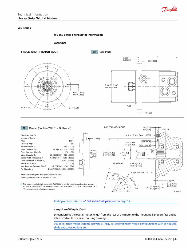
WS 360 Series Short Motor Information
Housings
22.0 [.866]
F
Ø100.00 [3.937]Ø99.95 [3.935]
Ø11.3 [.445]Ø11.0 [.433]
Ø125 [4.92] Ø146 [5.75]
16 [.63]
6.2 [.244]5.8 [.228]
R.05
Lo
Ø108.0 [4.252]Ø107.6 [4.236]
35.5 [1.398]34.5 [1.358]
Ø100 [3.94]
Ø4 [.16]
O-Ring
M10 x 1.5, Min. Depth 15 [.59]
A
2.3 [.091]27.3 [1.075]26.7 [1.051]52.3 [2.059]
51.7 [2.035]
8.4 [.331]8.0 [.315]
33 [1.30]31 [1.22]
Ø29.5 [1.161]Ø28.5 [1.122]
34.4 [1.355] Min.
Ø40 [1.57]Min.
d
Dri
D fi
D i
D
R
So
l
Fillet Root Side FitNumber of Teeth 12Pitch 12/24Pressure Angle 30°Pitch Diameter D 25.4 [1.000]Major Diameter Dri 28.0 [1.10] - 27.9 [1.096]Form Diameter (Min.) Dfi 27.6 [1.09]Minor Diameter Di 23.033 [.9068] - 23.0 [.9055]Space Width (Circular) Lo* 4.328 [.1704] - 4.288 [.1688]Tooth Thickness (Circular) So 2.341 [.09217]Fillet Radius R min 0.2 [.008]Max. Distance Between Pins I 17.77 [.700] - 17.62 [.694]Pin Diameter d 4.836 [.19034] - 4.834 [.19026]
Internal involute spline data per ANSI B92.1-1970,class 5 (corrected m • X = 0.8; m = 2.1166)
0.25 A
0.2/100 A
C
4-HOLE, SHORT MOTOR MOUNT SH Side Ports
INPUT DIMENSIONS00 Cardan (For Use With The SH Mount)
The recommended shaft material is SAE 8620 or similar case hardening steel such as20 MoCr4 (900 N/mm2) hardened to 59 - 62 HRc to a depth of 0.762 - 1.016 [.030 - .040].*Dimensions apply after heat treatment.
P109421
Porting options listed in WS 360 Series Porting Options on page 35.
Length and Weight Chart
Dimension F is the overall motor length from the rear of the motor to the mounting flange surface and isreferenced on the detailed housing drawing.
360 series short motor weights can vary ± 1kg [2 lb] depending on model configurations such as housing,shaft, endcover, options etc.
Technical InformationHeavy Duty Orbital Motors
WS Series
© Danfoss | Dec 2017 BC00000386en-US0201 | 39

Dimension F
# Length Weight
mm [in] kg [lb]
080 125 [4.92] 7.8 [17.2]
100 129 [5.08] 8.1 [17.9]
125 129 [5.08] 8.1 [17.9]
160 134 [5.28] 8.6 [19.0]
200 141 [5.55] 9.0 [19.8]
230 155 [6.10] 9.8 [21.6]
250 148 [5.83] 9.5 [20.9]
315 158 [6.22] 10.0 [22.0]
400 173 [6.81] 10.9 [24.0]
500 188 [7.40] 11.8 [26.0]
Technical InformationHeavy Duty Orbital Motors
WS Series
40 | © Danfoss | Dec 2017 BC00000386en-US0201

WS 360 Series Ultra Short Motor Information
Housings - U8 Mount
7.0 [.276]
G
Ø74.96 [2.951]Ø74.88 [2.949]100 [3.94]
Ø104 [4.09]74 x 3mm O-Ring
(4) M10x1.5
Lo
d
Dri
D fi
D i
D
R
So
l
Fillet Root Side FitNumber of Teeth 12Pitch 12/24Pressure Angle 30°Pitch Diameter D 25.4 [1.000]Major Diameter Dri 28.0 [1.10] - 27.9 [1.096]Form Diameter (Min.) Dfi 27.6 [1.09]Minor Diameter Di 23.033 [.9068] - 23.0 [.9055]Space Width (Circular) Lo* 4.328 [.1704] - 4.288 [.1688]Tooth Thickness (Circular) So 2.341 [.09217]Fillet Radius R min 0.2 [.008]Max. Distance Between Pins I 17.77 [.700] - 17.62 [.694]Pin Diameter d 4.836 [.19034] - 4.834 [.19026]
Internal involute spline data per ANSI B92.1-1970,class 5 (corrected m • X = 0.8; m = 2.1166)
50 [1.97] 54 [2.13]
45°
KØ4 [.16]
Min.
A
C
B
Ø4 [.16] Min.
Ø110 [4.33]Min.
82.02 [3.229]82.00 [3.228]
75.08 [2.956]75.02 [2.954]
Ø40 [1.57]Min.
Ø35.5 [1.40]Ø34.5 [1.36]
Ø29.5 [1.16]Ø28.5 [1.12]
Ø 0.25 K
1.6
1.6
15 [.59] Min. 2.35 [.093]2.25 [.089]
A - Hardened Stop PlateB - Oil Circulation HoleC - Oil Circulation Hole
0.00646.3 [1.82]45.7 [1.80]
8.0 [.315]7.5 [.295]
.9 [.035]
.1 [.004]20 [.79]18 [.71]
4-HOLE, ULTRA SHORT MOTOR MOUNT U8 Side Ports
INPUT DIMENSIONS00 Cardan (For Use With The U8 Mount)
The recommended shaft material is SAE 8620 or similar case hardening steel such as 20 MoCr4 (900 N/mm2) hardened to 59 - 62 HRc to a depth of 0.762 - 1.016 [.030 - .040].*Dimensions apply after heat treatment.
P109422
Porting options listed in WS 360 Series Porting Options on page 35.
Technical InformationHeavy Duty Orbital Motors
WS Series
© Danfoss | Dec 2017 BC00000386en-US0201 | 41

Length and Weight Chart - U8 Mount
Dimension G is the overall motor length from the rear of the motor to the mounting flange surface and isreferenced on the detailed housing drawing.
360 series ultra short motor weights can vary ± 1kg [2 lb] depending on model configurations such ashousing, shaft, endcover, options etc.
Dimension G
# Length Weight
mm [in] kg [lb]
080 106 [4.16] 6.3 [13.9]
100 110 [4.32] 6.6 [14.6]
125 110 [4.32] 6.6 [14.6]
160 115 [4.54] 7.1 [15.7]
200 122 [4.79] 7.5 [16.5]
250 129 [5.09] 8.0 [17.6]
Technical InformationHeavy Duty Orbital Motors
WS Series
42 | © Danfoss | Dec 2017 BC00000386en-US0201

Housings - V8 Mount
16.0 [.630]
H
Ø90.00 [3.543]Ø89.95 [3.541]100 [3.94]
Ø104 [4.09] 85 x 2mm O-Ring
(4) M10x1.5
Lo
d
Dri
D fi
D i
D
R
So
l
Fillet Root Side FitNumber of Teeth 12Pitch 12/24Pressure Angle 30°Pitch Diameter D 25.4 [1.000]Major Diameter Dri 28.0 [1.10] - 27.9 [1.096]Form Diameter (Min.) Dfi 27.6 [1.09]Minor Diameter Di 23.033 [.9068] - 23.0 [.9055]Space Width (Circular) Lo* 4.328 [.1704] - 4.288 [.1688]Tooth Thickness (Circular) So 2.341 [.09217]Fillet Radius R min 0.2 [.008]Max. Distance Between Pins I 17.77 [.700] - 17.62 [.694]Pin Diameter d 4.836 [.19034] - 4.834 [.19026]
Internal involute spline data per ANSI B92.1-1970,class 5 (corrected m • X = 0.8; m = 2.1166)
50 [1.97] 54 [2.13]
45°
Ø4 [.16] Min.
Ø104.15 [4.100]Ø103.85 [4.089]
0.10.006
A46.4 [1.827]45.6 [1.795]
A
Ø90.05 [3.545]Ø90.00 [3.543]
Ø 0.25 K
KØ29.5 [1.161]Ø28.5 [1.122]
Ø40 [1.57]Min.
Ø52 [2.05]Max.
Ø35.5 [1.398]Ø34.5 [1.358]
A
BC
26.1 [1.028]25.9 [1.020]
26 [1.02] Min.
15.5 [.610]15.0 [.591]
1.9 [.075]1.1 [.043]
20°
2.0 [.079]1.6 [.063]
A - Hardened Stop PlateB - Oil Circulation HoleC - Internal Spline Dp 12/24 ANSI B92.1-76
4-HOLE, ULTRA SHORT MOTOR MOUNT V8 Side Ports
INPUT DIMENSIONS00 Cardan (For Use With The V8 Mount)
The recommended shaft material is SAE 8620 or similar case hardening steel such as 20 MoCr4 (900 N/mm2) hardened to 59 - 62 HRc to a depth of 0.762 - 1.016 [.030 - .040].*Dimensions apply after heat treatment.
P109423
Porting options listed in WS 360 Series Porting Options on page 35.
Length and Weight Chart - V8 Mount
Dimension H is the overall motor length from the rear of the motor to the mounting flange surface and isreferenced on the detailed housing drawing.
Technical InformationHeavy Duty Orbital Motors
WS Series
© Danfoss | Dec 2017 BC00000386en-US0201 | 43

360 series ultra short motor weights can vary ± 1kg [2 lb] depending on model configurations such ashousing, shaft, endcover, options etc.
Dimension H
# Length Weight
mm [in] kg [lb]
080 100 [3.92] 6.3 [13.9]
100 104 [4.08] 6.6 [14.6]
125 104 [4.08] 6.6 [14.6]
160 109 [4.31] 7.1 [15.7]
200 116 [4.56] 7.5 [16.5]
250 123 [4.86] 8.0 [17.6]
WS 360 Series Ordering Information
1 2 3b3a 4 5 6 7 8
80 cm3/rev [4.9 in3/rev]
100 cm3/rev [6.1 in3/rev]
125 cm3/rev [7.6 in3/rev]
160 cm3/rev [9.7 in3/rev]
200 cm3/rev [12.2 in3/rev]
Clockwise Rotation
The 360 series is bi-directional. Reversing the inlet hose will reverse shaft rotation.
The SH, U8 and V8 Mounts are only available with the 00 cardan shaft.
226 cm3/rev [13.8 in3/rev]
250 cm3/rev [15.2 in3/rev]
305 cm3/rev [18.6 in3/rev]
393 cm3/rev [24.0 in3/rev]
493 cm3/rev [30.1 in3/rev]
2-Hole, SAE A Mount
6-Hole, Magneto Mount
4-Hole, SAE A Mount
4-Hole, Square Euro Mount
2-Hole, SAE B Mount
4-Hole, Short Motor Mount
4-Hole, Ultra Short (75mm Pilot)
4-Hole, Ultra Short (90mm Pilot)
4-Hole, Wheel Mount (5” Pilot)
4-Hole, Wheel Mount (125mm Pilot)
Cardan
1” Straight
25mm Straight
1-1/4” Straight
32mm Straight
14 Tooth Spline, 3/8” Tap
1-1/2” Tapered
1-3/8” 6B Spline PTO
1” 6B Spline
14 Tooth Spline, M8 Tap
35mm Tapered
1-1/4” Tapered
Black
Black, Unpainted Mounting Surface
No Paint
Standard
None
None
7/8-14 UNF Offset Manifold
G 1/2 Offset Manifold
M22x1.5 Offset Manifold
The cardan shaft is only available with the SH, U8 and V8 Mounts.
The SH, U8 and V8 mounts are only available with no paint.
080100125160200
230250315400500
134
360
1. CHOOSE SERIES DESIGNATION
2. SELECT A DISPLACEMENT OPTION
SIDE MOUNT
3a. SELECT MOUNT TYPE 3b. SELECT PORT SIZE
A7ATAHAUB7SHU8V8W8Z8
4. SELECT A SHAFT OPTION
5. SELECT A PAINT OPTION
ABZ
6. SELECT A VALVE CAVITY / CARTRIDGE OPTION
7. SELECT AN ADD-ON OPTION
A
8. SELECT A MISCELLANEOUS OPTION
AA
ASIDE PORT OPTIONS
001012202123
3178G4N3N4N5
P109424
Technical InformationHeavy Duty Orbital Motors
WS Series
44 | © Danfoss | Dec 2017 BC00000386en-US0201

Technical InformationHeavy Duty Orbital Motors
© Danfoss | Dec 2017 BC00000386en-US0201 | 45

Technical InformationHeavy Duty Orbital Motors
46 | © Danfoss | Dec 2017 BC00000386en-US0201

Technical InformationHeavy Duty Orbital Motors
© Danfoss | Dec 2017 BC00000386en-US0201 | 47
Danfoss Power Solutions is a global manufacturer and supplier of high-quality hydraulic andelectronic components. We specialize in providing state-of-the-art technology and solutionsthat excel in the harsh operating conditions of the mobile off-highway market. Building onour extensive applications expertise, we work closely with our customers to ensureexceptional performance for a broad range of off-highway vehicles.
We help OEMs around the world speed up system development, reduce costs and bringvehicles to market faster.
Danfoss – Your Strongest Partner in Mobile Hydraulics.
Go to www.powersolutions.danfoss.com for further product information.
Wherever off-highway vehicles are at work, so is Danfoss. We offer expert worldwide supportfor our customers, ensuring the best possible solutions for outstanding performance. Andwith an extensive network of Global Service Partners, we also provide comprehensive globalservice for all of our components.
Please contact the Danfoss Power Solution representative nearest you.
Local address:
Danfoss Power Solutions GmbH & Co. OHGKrokamp 35D-24539 Neumünster, GermanyPhone: +49 4321 871 0
Danfoss Power Solutions ApSNordborgvej 81DK-6430 Nordborg, DenmarkPhone: +45 7488 2222
Danfoss Power Solutions (US) Company2800 East 13th StreetAmes, IA 50010, USAPhone: +1 515 239 6000
Danfoss Power Solutions Trading(Shanghai) Co., Ltd.Building #22, No. 1000 Jin Hai RdJin Qiao, Pudong New DistrictShanghai, China 201206Phone: +86 21 3418 5200
Danfoss can accept no responsibility for possible errors in catalogues, brochures and other printed material. Danfoss reserves the right to alter its products without notice. This also applies to productsalready on order provided that such alterations can be made without changes being necessary in specifications already agreed.All trademarks in this material are property of the respective companies. Danfoss and the Danfoss logotype are trademarks of Danfoss A/S. All rights reserved.
© Danfoss | Dec 2017 BC00000386en-US0201
Products we offer:
• Bent Axis Motors
• Closed Circuit Axial PistonPumps and Motors
• Displays
• Electrohydraulic PowerSteering
• Electrohydraulics
• Hydraulic Power Steering
• Integrated Systems
• Joysticks and ControlHandles
• Microcontrollers andSoftware
• Open Circuit Axial PistonPumps
• Orbital Motors
• PLUS+1® GUIDE
• Proportional Valves
• Sensors
• Steering
• Transit Mixer Drives
Comatrolwww.comatrol.com
Turolla www.turollaocg.com
Hydro-Gearwww.hydro-gear.com
Daikin-Sauer-Danfosswww.daikin-sauer-danfoss.com