heavy duty service manual md - conmet · pdf filepreset ® hub assemblies preset plus...
TRANSCRIPT

PreSet ®
Hub Assemblies
PreSet Plus ™
Hub Assemblies
StandardHub Assemblies
Service Manual For Steer, Drive & Trailer Hub Assemblies
HDHEAVY DUTY
For All ConMet Hubs
MDMEDIUM DUTY
ABOUT THIS MANUALAbout This Manual
� Read this manual carefully, providing extra attention to its explanations and instructions.
� To ensure safe, continuous, trouble-free operation, understand your wheel hub system, and keep all components in proper operating condition.
� Pay particular attention to all NOTES, CAUTIONS, WARNINGS, and DANGERS to avoid the risk of personal injury or property damage, and realize these statements are not exhaustive. ConMet cannot possibly know or evaluate all conceivable methods in which service may be performed or the possibly hazardous consequences of each method. Accordingly, those who use a procedure not recommended by ConMet must first satisfy themselves that neither their safety nor the safety of the product will be jeopardized by the service method selected.
� Use only ConMet approved replacement parts. Do not attempt to use damaged parts.
The following decals are available upon request.
Before You Begin
1. Read and understand all instructions and procedures before you begin to service components.
2. Read and observe all Warning and Caution hazard alert messages in this publication. They provide information that can help prevent serious personal injury, damage to components, or both.
3. Follow your companyʼs maintenance and service, installation, and diagnostics guidelines.
4. Use special tools when required to help avoid serious personal injury and damage to components.
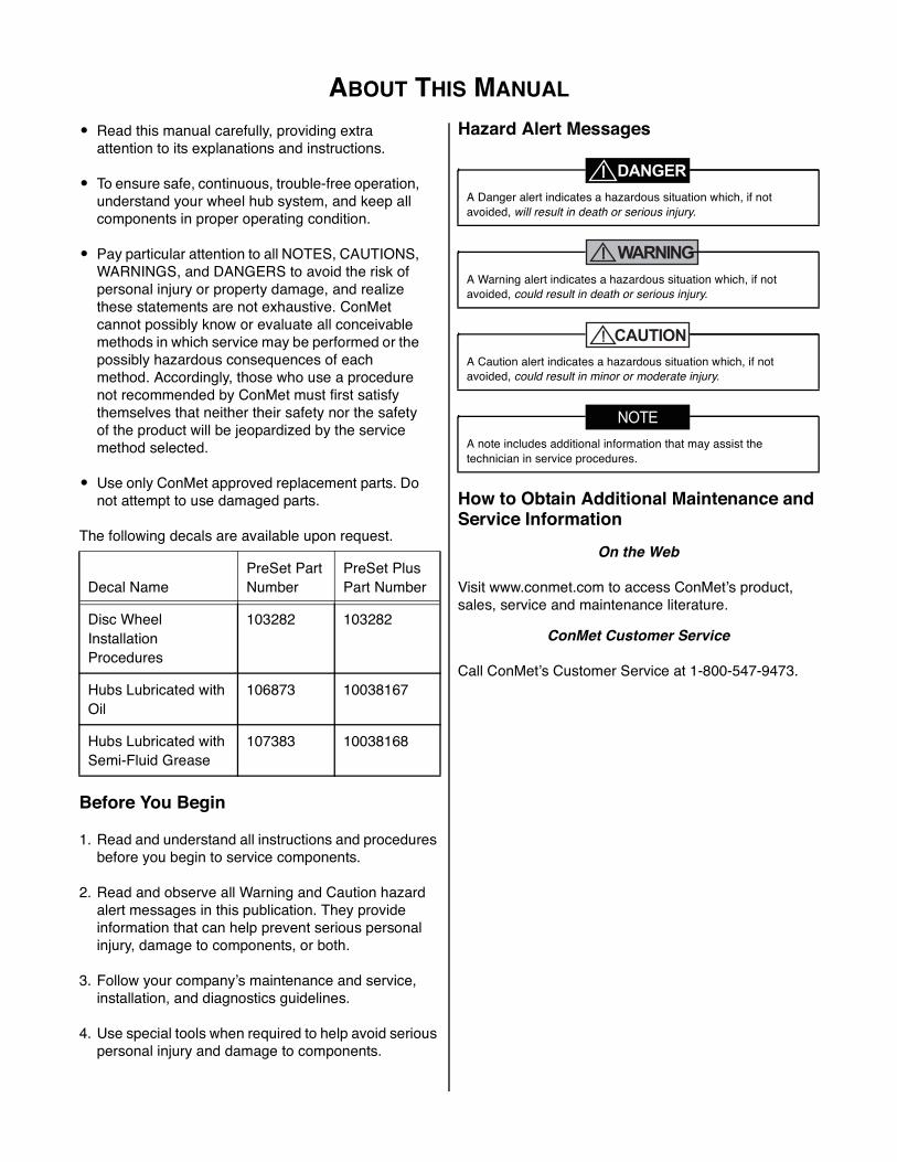
Hazard Alert Messages
WARNING
How to Obtain Additional Maintenance and Service Information
On the Web
Visit www.conmet.com to access ConMetʼs product, sales, service and maintenance literature.
ConMet Customer Service
Call ConMetʼs Customer Service at 1-800-547-9473.
Decal NamePreSet Part Number
PreSet Plus Part Number
Disc Wheel Installation Procedures
103282 103282
Hubs Lubricated with Oil
106873 10038167
Hubs Lubricated with Semi-Fluid Grease
107383 10038168
A Danger alert indicates a hazardous situation which, if not avoided, will result in death or serious injury.
A Warning alert indicates a hazardous situation which, if not avoided, could result in death or serious injury.
A Caution alert indicates a hazardous situation which, if not avoided, could result in minor or moderate injury.
A note includes additional information that may assist the technician in service procedures.
TABLE OF CONTENTSTable of Contents
1. INTRODUCTION ........................................................................................................................................ 1Standard Hubs ........................................................................................................................................ 1PreSet Hub Assemblies .......................................................................................................................... 1PreSet Plus Hub Assemblies .................................................................................................................. 1
2. IDENTIFICATION ....................................................................................................................................... 3WHEEL MOUNTING SYSTEMS ................................................................................................................ 3
Hub Pilot Wheel Mounting ...................................................................................................................... 3Ball Seat Wheel Mounting System ......................................................................................................... 3
IDENTIFYING CONMET HUB ASSEMBLIES ............................................................................................ 3Vehicle Identification Number (VIN) ........................................................................................................ 3Casting Number ...................................................................................................................................... 3Machining Assembly Number ................................................................................................................. 3Final Hub Assembly Number .................................................................................................................. 4Julian Date .............................................................................................................................................. 4
3. INSPECTION .............................................................................................................................................. 5HAZARD ALERT MESSAGES ................................................................................................................... 5WHEEL END INSPECTION GENERAL GUIDELINES ............................................................................... 5
Driver Pre-Trip Visual Inspection ............................................................................................................. 5In Route Inspections ................................................................................................................................ 5Preventative Maintenance Schedule ....................................................................................................... 5Five Years or 500,000 Miles .................................................................................................................... 6Lubrication Analysis................................................................................................................................. 6
4. RECOMMENDED SERVICE ...................................................................................................................... 7HUB REMOVAL AND DISASSEMBLY ....................................................................................................... 7COMPONENT INSPECTION AND REPLACEMENT HAZARD ALERT MESSAGES ............................... 9CLEAN AND DRY COMPONENTS ............................................................................................................ 9
Worn or Damaged Components ............................................................................................................. 9Hub and Component Cleaning ............................................................................................................... 9
INSPECTING BEARING CUPS AND CONES AND BEARING SPACER ................................................ 10REMOVING CUPS IN ALUMINUM HUBS ................................................................................................ 10REMOVING CUPS IN IRON HUBS .......................................................................................................... 11INSTALLING A NEW CUP IN ALUMINUM HUBS .................................................................................... 11INSTALLING A NEW CUP IN IRON HUBS .............................................................................................. 11WHEEL STUDS ........................................................................................................................................ 11STUD REMOVAL ...................................................................................................................................... 11STUD REPLACEMENT ............................................................................................................................ 11HUB, DRUM AND WHEEL INSPECTION ................................................................................................ 12ABS TONE RING INSPECTION (AS APPLICABLE) ................................................................................ 12REMOVAL AND INSTALLATION OF ABS TONE RING .......................................................................... 12REMOVAL AND INSTALLATION OF STAMPED STEEL ABS TONE RING ........................................... 12REMOVAL AND INSTALLATION OF BOLT ON ABS TONE RINGS ....................................................... 13
5. REASSEMBLY ......................................................................................................................................... 14REASSEMBLY OF PreSet WHEEL HUBS ............................................................................................... 14REASSEMBLY OF PreSet Plus WHEEL HUBS ....................................................................................... 16
6. REINSTALLATION ................................................................................................................................... 17IDENTIFYING HUB TO BE INSTALLED .................................................................................................. 17INSTALLING ConMet STANDARD HUBS ................................................................................................ 18INSTALLING THE PreSet WHEEL HUB ASSEMBLY .............................................................................. 19INSTALLING THE PreSet Plus WHEEL HUB ASSEMBLY ...................................................................... 20
7. LUBRICATION ......................................................................................................................................... 21DRIVE HUB LUBRICATION ..................................................................................................................... 21STEER AND TRAILER HUBS WITH OIL LUBRICANT ............................................................................ 21TRAILER HUBS WITH SEMI-FLUID GREASE LUBRICANT ................................................................... 21
8. BRAKE DRUM AND WHEEL INSTALLATION ....................................................................................... 23Hub Pilot Wheel Mounting System ....................................................................................................... 23Ball Seat Wheel Mounting System ....................................................................................................... 24
SERVICE PARTS LIST ................................................................................................................................ 27WHEEL END TORQUE SPECIFICATIONS ................................................................................................. 30
1. INTRODUCTION
Consolidated Metco, Inc. 1
5Introduction
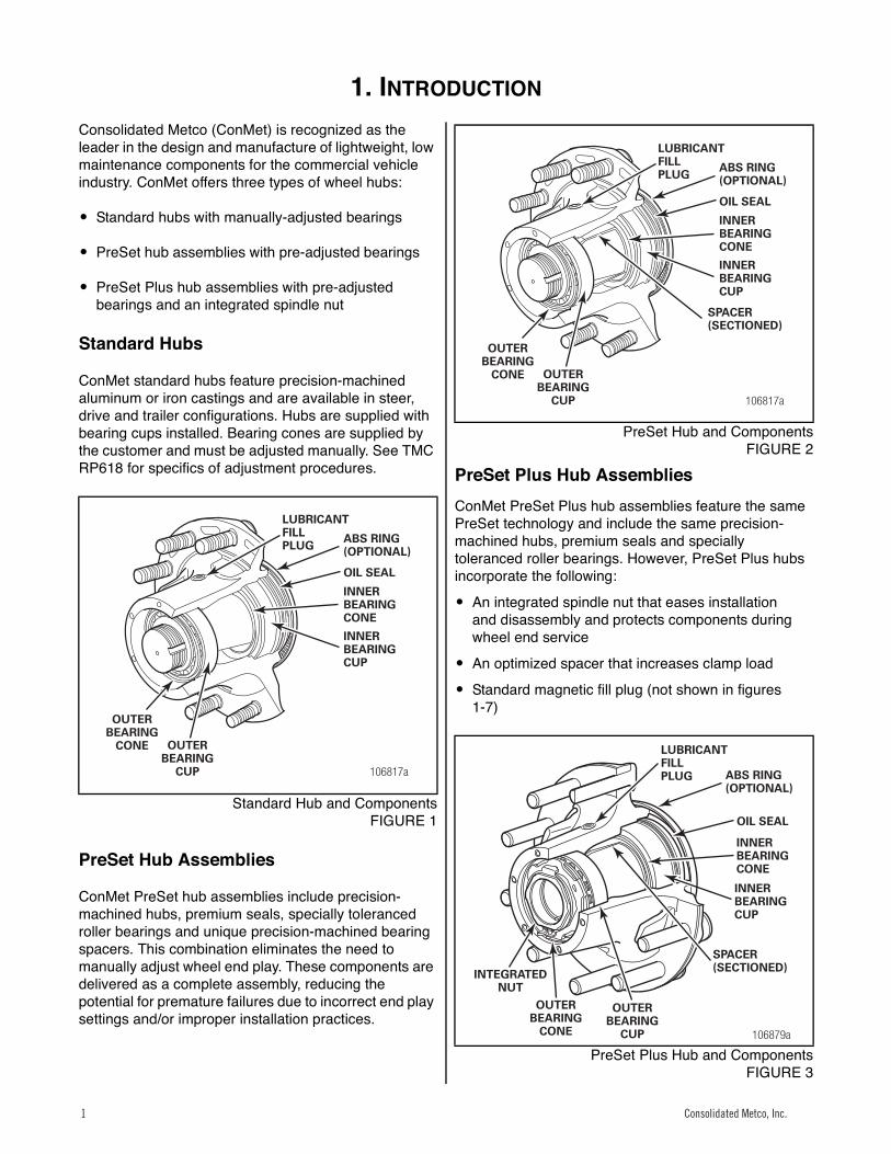
Consolidated Metco (ConMet) is recognized as the leader in the design and manufacture of lightweight, low maintenance components for the commercial vehicle industry. ConMet offers three types of wheel hubs:
� Standard hubs with manually-adjusted bearings
� PreSet hub assemblies with pre-adjusted bearings
� PreSet Plus hub assemblies with pre-adjusted bearings and an integrated spindle nut
Standard Hubs
ConMet standard hubs feature precision-machined aluminum or iron castings and are available in steer, drive and trailer configurations. Hubs are supplied with bearing cups installed. Bearing cones are supplied by the customer and must be adjusted manually. See TMC RP618 for specifics of adjustment procedures.1
Standard Hub and ComponentsFIGURE 1
PreSet Hub Assemblies
ConMet PreSet hub assemblies include precision- machined hubs, premium seals, specially toleranced roller bearings and unique precision-machined bearing spacers. This combination eliminates the need to manually adjust wheel end play. These components are delivered as a complete assembly, reducing the potential for premature failures due to incorrect end play settings and/or improper installation practices.
1
PreSet Hub and ComponentsFIGURE 2
PreSet Plus Hub AssembliesConMet PreSet Plus hub assemblies feature the same PreSet technology and include the same precision- machined hubs, premium seals and specially toleranced roller bearings. However, PreSet Plus hubs incorporate the following:
� An integrated spindle nut that eases installation and disassembly and protects components during wheel end service
� An optimized spacer that increases clamp load
� Standard magnetic fill plug (not shown in figures 1-7)
1
PreSet Plus Hub and ComponentsFIGURE 3
106817a
LUBRICANTFILLPLUG
ABS RING(OPTIONAL)
OIL SEAL
INNERBEARINGCONE
INNERBEARINGCUP
OUTERBEARING
CUP
OUTERBEARING
CONE
106817a
LUBRICANTFILLPLUG
ABS RING(OPTIONAL)
OIL SEAL
INNERBEARINGCONE
INNERBEARINGCUP
SPACER(SECTIONED)
OUTERBEARING
CUP
OUTERBEARING
CONE
106879a
ABS RING(OPTIONAL)
OIL SEAL
INNERBEARINGCONE
INNERBEARINGCUP
SPACER(SECTIONED)
OUTERBEARING
CUP
OUTERBEARING
CONE
INTEGRATEDNUT
LUBRICANTFILLPLUG
Consolidated Metco, Inc.1 Consolidated Metco, Inc.1

1. INTRODUCTION
2 Consolidated Metco, Inc.
2
Steer Hub and ComponentsFIGURE 4
3
Drive Hub and ComponentsFIGURE 5
4
TN Trailer Hub and ComponentsFIGURE 6
5
TP Trailer Hub and ComponentsFIGURE 7
106876a
MACHINEDSTEER HUB
PRESETCOMPONENTS
PRESET PLUSCOMPONENTS
106818a
MACHINEDDRIVE HUB
PRESETCOMPONENTS
PRESET PLUSCOMPONENTS
106819a
MACHINEDTN TRAILER HUB
PRESETCOMPONENTS
PRESET PLUSCOMPONENTS
106820a
MACHINEDTP TRAILER HUB
PRESETCOMPONENTS
PRESET PLUSCOMPONENTS
Consolidated Metco, Inc. 2Consolidated Metco, Inc. 2

2. IDENTIFICATION
Consolidated Metco, Inc. 3
Identification
WHEEL MOUNTING SYSTEMS
ConMet wheel hubs are available in both hub pilot and ball seat nut configurations.
Hub Pilot Wheel Mounting
The hub pilot wheel mounting system makes use of a single two-piece flange nut on each wheel stud for both single and dual wheel applications (see figure 8). The hub pilot wheel mounting system is also known as the Uni-Mount-10™ (10 stud), WHD-10™ (10 stud), WHD-8™ (8 stud), and ISO system.6
Hub Pilot Mounting SystemsFIGURE 8
Ball Seat Wheel Mounting System
The ball seat wheel mounting system makes use of the spherical contact area between the nut and wheel to both locate the wheel and hold the wheel tight against the brake drum (see figure 9).
The ball seat wheel mounting system is also known as the stud piloted, ball seat cap nut (BCN) and double cap nut (DCN) system.7
Ball Seat Mounting SystemsFIGURE 9
IDENTIFYING CONMET HUB ASSEMBLIES
Identifying your hub assembly is important for many reasons. It will enable you to properly service the hub assembly and purchase the appropriate replacement parts if needed. Plus, if a warranty issue arises, youʼll then be able to provide details on all aspects of the ConMet hub. This section is devoted to finding and understanding the different identification numbers associated with ConMet hubs.
Vehicle Identification Number (VIN)
The quickest and easiest method of identifying your hub assembly is to note the vehicle identification number (VIN) and call the truck dealership. The dealership can then tell you what hubs were installed on your vehicle. If this is not possible, there is a variety of identification numbers located on a ConMet hub assembly.
Casting Number
This number is physically cast into the hub and appears in large characters usually on the back side of the mounting flange near the stud head (see figure 10).8
Casting Number on the Back Side of the Mounting FlangeFIGURE 10
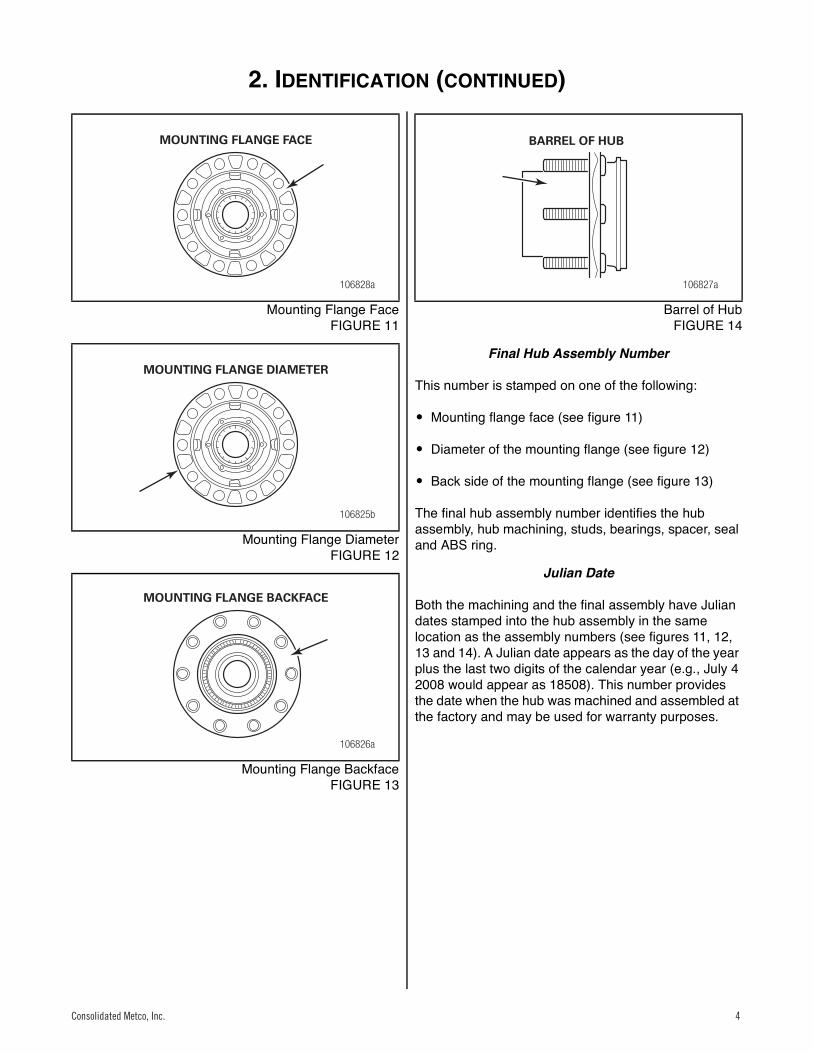
Machining Assembly Number
This number is stamped on one of the following:
� Mounting flange face (see figure 11)
� Diameter of the mounting flange (see figure 12)
� Back side of the mounting flange (see figure 13)
� Barrel of the hub (see figure 14)
The machining number represents the way the hub is machined (e.g., hub pilot vs. ball seat, 8.78" vs. 8.53" vs. 9" brake drum pilot diameter).
106821a
SINGLE DUAL
106822a
SINGLE DUAL
106829a
CASTING NUMBER ON THE BACK SIDE OF THE
MOUNTING FLANGE
Consolidated Metco, Inc.3 Consolidated Metco, Inc.3
2. IDENTIFICATION (CONTINUED)
4 Consolidated Metco, Inc.
9
Mounting Flange FaceFIGURE 11
10
Mounting Flange DiameterFIGURE 12
11
Mounting Flange BackfaceFIGURE 13
12
Barrel of HubFIGURE 14
Final Hub Assembly Number
This number is stamped on one of the following:
� Mounting flange face (see figure 11)
� Diameter of the mounting flange (see figure 12)
� Back side of the mounting flange (see figure 13)
The final hub assembly number identifies the hub assembly, hub machining, studs, bearings, spacer, seal and ABS ring.
Julian Date
Both the machining and the final assembly have Julian dates stamped into the hub assembly in the same location as the assembly numbers (see figures 11, 12, 13 and 14). A Julian date appears as the day of the year plus the last two digits of the calendar year (e.g., July 4 2008 would appear as 18508). This number provides the date when the hub was machined and assembled at the factory and may be used for warranty purposes.
106828a
MOUNTING FLANGE FACE
106825b
MOUNTING FLANGE DIAMETER
106826a
MOUNTING FLANGE BACKFACE
106827a
BARREL OF HUB
Consolidated Metco, Inc. 4Consolidated Metco, Inc. 4
3. INSPECTION
Consolidated Metco, Inc. 5
Inspection
HAZARD ALERT MESSAGESRead and observe all Warning and Caution hazard alert messages in this publication. They provide information that can help prevent serious personal injury, damage to components, or both.
WARNING
WHEEL END INSPECTION GENERAL GUIDELINES
Wheel end service and maintenance requirements will vary based on vehicle operating conditions, vehicle specifications, lubrication type, and vehicle performance history. Consolidated Metco recommends the maintenance schedule below, in conjunction with TMC RP631A, to be adjusted as needed for varying conditions.
Driver Pre-Trip Visual InspectionVisually inspect the vehicle prior to operation. Include the following items:
1. Check for loose, damaged, or missing fasteners on the wheel and hub cap or axle. Rust or oil streaks coming from the wheel bolts may be a sign of improper wheel bolt torque.
2. Check for loose, damaged, or missing hubcaps.
3. Check for lubricant leaks at:
– Hubcap
– Drive axle flange gasket
– Oil fill plug
– Oil seal leakage – indicated by lubricant on the hub, brake components or inside of the wheel
4. Check lubricant condition via hub cap window on steer and trailer hubs. Lubricant that is darkened, milky, shows water in it, or has large metallic particles in it is indicative of contamination or a part failure and must be replaced. Contaminated lubricant may be an indication of a leaking seal that should be replaced.
5. Check for insufficient lubricant level via hub cap window on steer and trailer hubs. Refill lubricant to the indicated fill level if required.
If any of the above conditions are found, place the vehicle out of service until the item can be repaired.
In Route Inspections
1. After making an in route stop, walk around the vehicle and inspect the hubs for any leaks (per item 3 under Driver Pre-Trip) and significant differences in temperature or excessive temperature. If excessive temperature is found, inspect and repair the wheel end as necessary. High temperatures and high loads may cause early bearing failure. Lubricant viscosity should be chosen based on expected operating temperatures.
Preventative Maintenance Schedule
During any routine preventative maintenance on the vehicle or axle (see your OEM guidelines and associated federal regulations), inspect the following items:
1. Check for loose, damaged, or missing fasteners on the wheel and hub cap. Rust or oil streaks coming from the wheel bolts may be a sign of improper wheel bolt torque.
2. Check for loose, damaged, or missing hubcaps.
3. Check for lubricant leaks at:
– Hubcap
– Drive axle flange gasket
– Oil fill plug
– Oil seal – indicated by lubricant on the hub, brake components or inside of the wheel
4. Check for insufficient lubricant level via hub cap window on steer and trailer hubs. Refill lubricant to the indicated fill level if required.
Do not work under a vehicle supported only by jacks. Jacks can slip and fall over. Serious personal injury and damage to components can result.To prevent serious eye injury, always wear safe eye protection when you perform vehicle maintenance or service.Park the vehicle on a level surface. Block the wheels to prevent the vehicle from moving. Support the vehicle with safety stands.
Operating temperature can be checked as the vehicle enters the service area following a normal run. If the hub is running in excess of 150°F above the ambient in normal operating conditions, service is required.
If any item is found to be out of specification during any of the inspection steps listed below, place the vehicle out of service until the item can be repaired or replaced.
Consolidated Metco, Inc.5 Consolidated Metco, Inc.5
3. INSPECTION (CONTINUED)
6 Consolidated Metco, Inc.
5. Check the lubricant condition. Lubricant that is darkened, milky, shows water in it or has large metallic particles in it is indicative of contamination or a part failure and must be replaced. Contaminated lubricant may be an indication of a leaking seal that should be replaced.– On oil lubricated hubs equipped with a fill plug
in the hubcap or barrel of the hub, place a magnet (or inspect the magnetic fill plug) in the lubricant and check for signs of large metallic particles picked up by the magnet. On drive axles, it is normal to find a small amount of very fine metallic particles from the carrier housing on the magnetic fill plug. These particles should be removed from the magnet anytime the plug is removed for inspection. If larger particles or chunks of metal are found, the hub should be removed from the spindle and the bearings and other components should be inspected for signs of damage or excessive wear.
– In vehicles without a fill plug in drive hubs inspect the lubricant volume and condition from the fill plug in the axle carrier housing.
– For vehicles lubricated with semi-fluid grease, inspect annually or every 100,000 miles. First, remove the hubcap and inspect the lubricant condition and volume. Verify the lubricant covers the ends of the bearing rollers. If the lubricant condition is good, add lubricant through the fill plug in the barrel of the hub to cover the ends of the bearing rollers. If the lubricant has a dry and caked appearance, remove the wheel end from the vehicle and clean and inspect all components. Replace damaged or worn components as necessary.
6. If regular schedule maintenance requires wheels/axle to be lifted, perform steps 7 and 8.
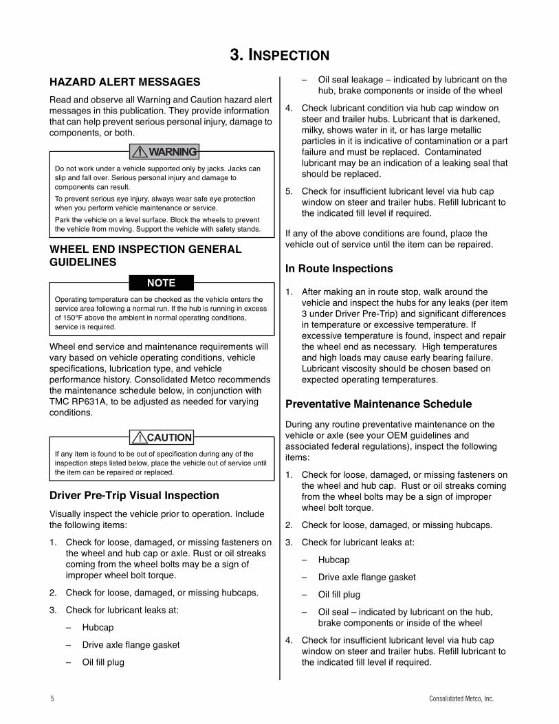
7. Lift and support the axle (see figure 15). Rotate the wheel. Check that the wheel rotates freely and smoothly. Listen and feel for any signs of rough bearing operation or vibration.
Figure 0.1
13
FIGURE 15
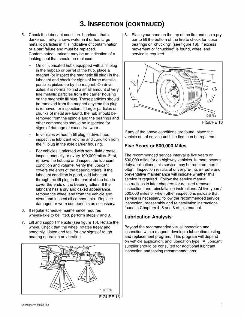
8. Place your hand on the top of the tire and use a pry bar to lift the bottom of the tire to check for loose bearings or "chucking" (see figure 16). If excess movement or "chucking" is found, wheel end service is required.
Figure 0.2
14
FIGURE 16
If any of the above conditions are found, place the vehicle out of service until the item can be repaired.
Five Years or 500,000 Miles
The recommended service interval is five years or 500,000 miles for on highway vehicles. In more severe duty applications, this service may be required more often. Inspection results at driver pre-trip, in-route and preventative maintenance will indicate whether this service is required. Follow the service manual instructions in later chapters for detailed removal, inspection, and reinstallation instructions. At five years/ 500,000 miles or when other inspections indicate that service is necessary, follow the recommended service, inspection, reassembly and reinstallation instructions found in Chapters 4, 5 and 6 of this manual.
Lubrication Analysis
Beyond the recommended visual inspection and inspection with a magnet, develop a lubrication testing and replacement program. This program will depend on vehicle application, and lubrication type. A lubricant supplier should be consulted for additional lubricant inspection and testing recommendations.
1003159a
106878a
Consolidated Metco, Inc. 6Consolidated Metco, Inc. 6
4. RECOMMENDED SERVICE
Consolidated Metco, Inc. 7
Recommended Service
At five years/500,000 miles or when other inspections indicate that service is necessary, follow the recommended service, inspection, reassembly and reinstallation instructions found in the following chapters.
In order to ensure optimum wheel hub performance, ConMet recommends that only approved PreSet service parts be used to replace all critical components of the system. Refer to the back of this manual for a listing of approved parts.
HUB REMOVAL AND DISASSEMBLY
WARNING
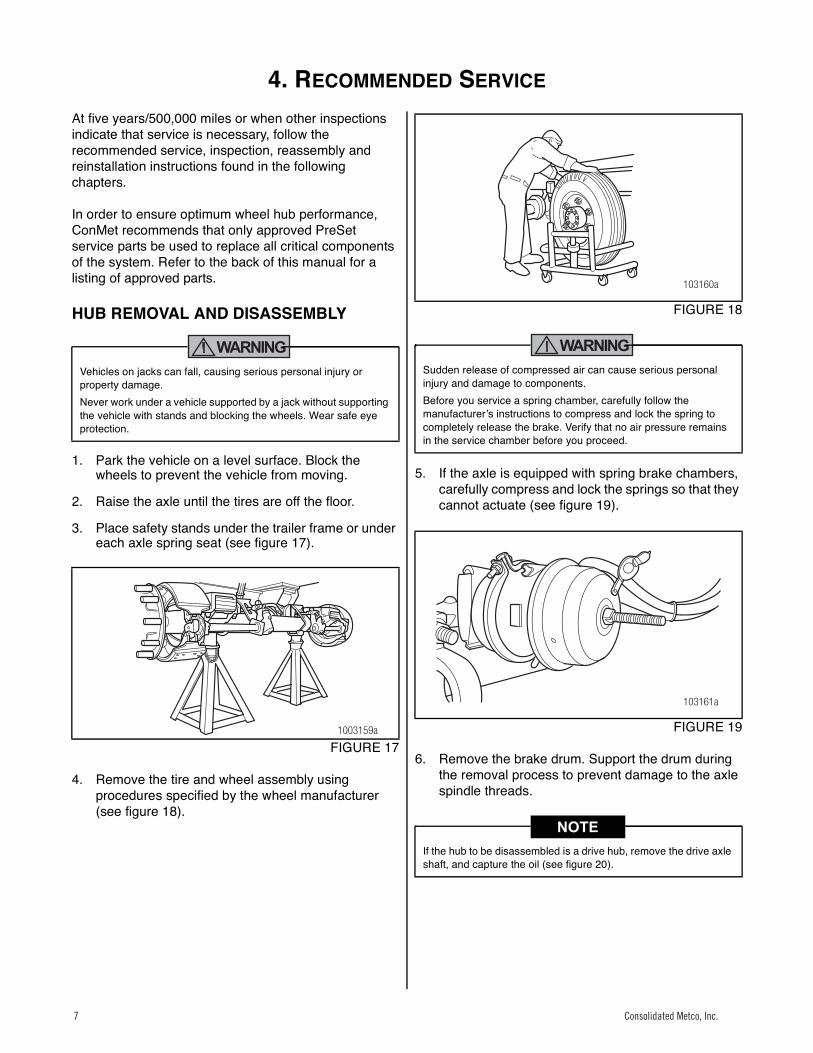
1. Park the vehicle on a level surface. Block the wheels to prevent the vehicle from moving.
2. Raise the axle until the tires are off the floor.
3. Place safety stands under the trailer frame or under each axle spring seat (see figure 17).
15
FIGURE 17
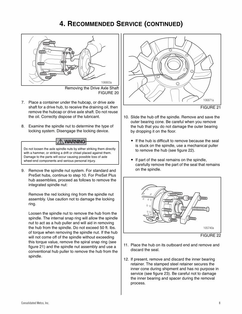
4. Remove the tire and wheel assembly using procedures specified by the wheel manufacturer (see figure 18).
16
FIGURE 18
WARNING
5. If the axle is equipped with spring brake chambers, carefully compress and lock the springs so that they cannot actuate (see figure 19).
17
FIGURE 19
6. Remove the brake drum. Support the drum during the removal process to prevent damage to the axle spindle threads.
Vehicles on jacks can fall, causing serious personal injury or property damage.Never work under a vehicle supported by a jack without supporting the vehicle with stands and blocking the wheels. Wear safe eye protection.
1003159a
Sudden release of compressed air can cause serious personal injury and damage to components.Before you service a spring chamber, carefully follow the manufacturerʼs instructions to compress and lock the spring to completely release the brake. Verify that no air pressure remains in the service chamber before you proceed.
If the hub to be disassembled is a drive hub, remove the drive axle shaft, and capture the oil (see figure 20).
103160a
103161a
Consolidated Metco, Inc.7 Consolidated Metco, Inc.7
4. RECOMMENDED SERVICE (CONTINUED)
8 Consolidated Metco, Inc.
18
Removing the Drive Axle ShaftFIGURE 20
7. Place a container under the hubcap, or drive axle shaft for a drive hub, to receive the draining oil, then remove the hubcap or drive axle shaft. Do not reuse the oil. Correctly dispose of the lubricant.
8. Examine the spindle nut to determine the type of locking system. Disengage the locking device.
WARNING
9. Remove the spindle nut system. For standard and PreSet hubs, continue to step 10. For PreSet Plus hub assemblies, proceed as follows to remove the integrated spindle nut:
Remove the red locking ring from the spindle nut assembly. Use caution not to damage the locking ring.
Loosen the spindle nut to remove the hub from the spindle. The internal snap ring will allow the spindle nut to act as a hub puller and will aid in removing the hub from the spindle. Do not exceed 50 ft. lbs. of torque when removing the spindle nut. If the hub will not come off of the spindle without exceeding this torque value, remove the spiral snap ring (see figure 21) and the spindle nut assembly and use a conventional hub puller to remove the hub from the spindle.
19
FIGURE 21
10. Slide the hub off the spindle. Remove and save the outer bearing cone. Be careful when you remove the hub that you do not damage the outer bearing by dropping it on the floor.
� If the hub is difficult to remove because the seal is stuck on the spindle, use a mechanical puller to remove the hub (see figure 22).
� If part of the seal remains on the spindle, carefully remove the part of the seal that remains on the spindle.
20
FIGURE 22
11. Place the hub on its outboard end and remove and discard the seal.
12. If present, remove and discard the inner bearing retainer. The stamped steel retainer secures the inner cone during shipment and has no purpose in service (see figure 23). Be careful not to damage the inner bearing and spacer during the removal process.
Do not loosen the axle spindle nuts by either striking them directly with a hammer, or striking a drift or chisel placed against them. Damage to the parts will occur causing possible loss of axle wheel-end components and serious personal injury.
106803a
106871a
105740a
Consolidated Metco, Inc. 8Consolidated Metco, Inc. 8

4. RECOMMENDED SERVICE (CONTINUED)
Consolidated Metco, Inc. 9
13. Remove the inner bearing and spacer.21
Hub Disassembly (Inner Bearing Retainer is not on Hubsequipped with CR Seals)
FIGURE 23
COMPONENT INSPECTION AND REPLACEMENT HAZARD ALERT MESSAGES
Read and observe all Warning and Caution hazard alert messages in this publication. They provide information that can help prevent serious personal injury, damage to components, or both.
WARNING
CLEAN AND DRY COMPONENTS
Worn or Damaged Components
WARNING
Hub and Component Cleaning
1. Use a cleaning solvent to clean the ground or polished parts and surfaces. Kerosene or diesel fuel can be used for this purpose. DO NOT USE GASOLINE.
2. Do NOT clean ground or polished parts in a hot solution tank or with water, steam or alkaline solutions. These solutions will cause corrosion of the parts.
3. Thoroughly clean the hub cavity with spray degreaser. The cavity must be free of any contaminants.
4. To remove grease from a wheel end, use a stiff fiber brush, not steel, and kerosene or diesel fuel, not gasoline. Allow the parts to dry. Note that any solvent residue must be completely wiped dry since it may either dilute the grease or oil or prevent the lubricant from correctly adhering to the wheel-end components.
5. Clean and inspect the wheel bearing cups and cones, race, spindle bearing and seal journals on the spindle, and hub. Bearings should be cleaned in a suitable non-flammable solvent and dried with either compressed air or a lint-free rag.
If compressed air is used, do not spin dry the bearings as the rollers may score due to lack of lubricant. Ensure that the air line is moisture free.
6. Parts must be dried immediately after cleaning. Dry parts with clean paper towels or rags, or compressed air. Do not dry bearings by spinning with compressed air.
7. Apply a light oil to cleaned and dried parts that are not damaged and are to be immediately assembled. Use only the type of oil used by the manufacturer. Do NOT apply oil to the brake linings or the brake drums.
To prevent serious eye injury, always wear safe eye protection when you perform vehicle maintenance or service.Observe all warnings and cautions provided by the press manufacturer to avoid damage to components and serious personal injury.Do not hit steel parts with a steel hammer. Pieces of a part can break off. Serious personal injury and damage to components can result. Use a brass or synthetic mallet for assembly and disassembly procedures.Solvent cleaners can be flammable, poisonous and cause burns. Examples of solvent cleaners are carbon tetrachloride, and emulsion-type and petroleum-base cleaners. Read the manufacturerʼs instructions before using a solvent cleaner, then carefully follow the instructions. Also follow the procedures below.� Wear safe eye protection.� Wear clothing that protects your skin.� Work in a well-ventilated area.� Do not use gasoline or solvents that contain gasoline.
Gasoline can explode.� You must use hot solution tanks or alkaline solutions
correctly. Read the manufacturerʼs instructions before using hot solution tanks and alkaline solutions. Then carefully follow the instructions.
Do not use hot solution tanks or water and alkaline solutions to clean ground or polished parts. Damage to parts can result.
106804a
INNERBEARING
RETAINER
INNERBEARING
CONE
SPACER
Do not repair or recondition wheel-end components. Replace damaged, worn or out-of-specification components. Do not mill or machine any components. Using repaired, reconditioned, damaged or worn components can cause wheel end failure, which can result in serious injury and property damage.
Consolidated Metco, Inc.9 Consolidated Metco, Inc.9
4. RECOMMENDED SERVICE (CONTINUED)
10 Consolidated Metco, Inc.
8. If the parts are to be stored, apply a good corrosion preventative to all surfaces. Do NOT apply the material to the brake linings or the brake drums. Store the parts inside special paper or other material that prevents corrosion.
INSPECTING BEARING CUPS AND CONES AND BEARING SPACER
1. After components have been properly cleaned, visually inspect the cups, cones and spacer for any wear or damage. Reference materials for proper bearing inspection procedures are available from the bearing manufacturers.
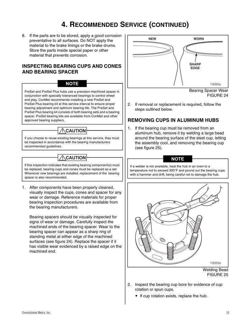
Bearing spacers should be visually inspected for signs of wear or damage. Carefully inspect the machined ends of the bearing spacer. Wear to the bearing spacer can appear as a sharp ring of standing metal at either edge of the machined surfaces (see figure 24). Replace the spacer if it has visible wear evidenced by a raised edge on the machined end.
22
Bearing Spacer WearFIGURE 24
2. If removal or replacement is required, follow the steps outlined below.
REMOVING CUPS IN ALUMINUM HUBS1. If the bearing cup must be removed from an
aluminum hub, remove it by welding a large bead around the bearing surface of the steel cup, letting the assembly cool, and removing the bearing cup (see figure 25).
23
Welding BeadFIGURE 25
2. Inspect the bearing cup bore for evidence of cup rotation or spun cups.� If cup rotation exists, replace the hub.
PreSet and PreSet Plus hubs use a precision-machined spacer in conjunction with specially toleranced bearings to control wheel end play. ConMet recommends installing a new PreSet and PreSet Plus bearing kit at this service interval to ensure proper bearing adjustment and optimum bearing life. The PreSet and PreSet Plus bearing kit consists of both bearing sets and a bearing spacer. PreSet bearing kits are available from ConMet and other approved bearing suppliers.
If you choose to reuse existing bearings at this service, they must be inspected in accordance with the bearing manufacturers recommended guidelines.
If this inspection indicates that existing bearing component(s) must be replaced, bearing cups and cones must be replaced as a set. Whenever new bearings are installed, replacement of the bearing spacer is also recommended.
If a welder is not available, heat the hub in an oven to a temperature not to exceed 300°F and pound out the bearing cups with a hammer and drift, being careful not to damage the hub.
106864a
NEW WORN
SHARPEDGE
106856a
Consolidated Metco, Inc. 10Consolidated Metco, Inc. 10
4. RECOMMENDED SERVICE (CONTINUED)
Consolidated Metco, Inc. 11
REMOVING CUPS IN IRON HUBS1. On an iron hub, remove the bearing cup using a
large hammer and a heavy drift or a hydraulic press. Take precaution to avoid damaging the bearing cup bore and shoulder.
2. Inspect the bearing cup bore for evidence of cup rotation or spun cups.� If cup rotation exists, replace the hub.
INSTALLING A NEW CUP IN ALUMINUM HUBSTo install a new cup in an aluminum hub, it is recommended that the hub be heated in boiling water (212°F) or in an oven at a temperature not to exceed 300°F. Cooling the cup in a freezer to 32°F or below will further ease the installation.
WARNING
Remove the aluminum hub from the oven or water and carefully drop in the new bearing cup being certain it is fully seated. If the cup is loose, allow a few seconds for it to heat up and secure itself before moving the hub. Use a 0.001″ to 0.002″ feeler gauge to ensure the cup is fully seated against the shoulder of the bearing bore.
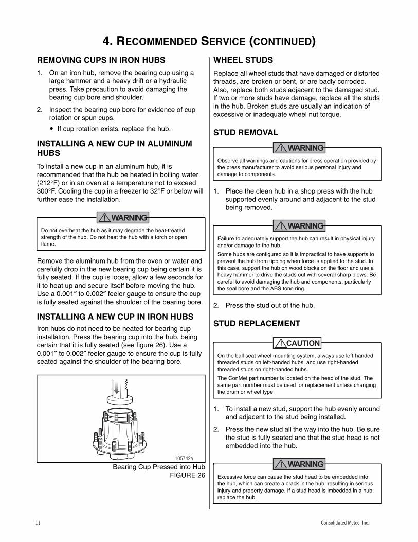
INSTALLING A NEW CUP IN IRON HUBSIron hubs do not need to be heated for bearing cup installation. Press the bearing cup into the hub, being certain that it is fully seated (see figure 26). Use a 0.001″ to 0.002″ feeler gauge to ensure the cup is fully seated against the shoulder of the bearing bore.24
Bearing Cup Pressed into HubFIGURE 26
WHEEL STUDSReplace all wheel studs that have damaged or distorted threads, are broken or bent, or are badly corroded. Also, replace both studs adjacent to the damaged stud. If two or more studs have damage, replace all the studs in the hub. Broken studs are usually an indication of excessive or inadequate wheel nut torque.
STUD REMOVAL
WARNING
1. Place the clean hub in a shop press with the hub supported evenly around and adjacent to the stud being removed.
WARNING
2. Press the stud out of the hub.
STUD REPLACEMENT
1. To install a new stud, support the hub evenly around and adjacent to the stud being installed.
2. Press the new stud all the way into the hub. Be sure the stud is fully seated and that the stud head is not embedded into the hub.
WARNING
Do not overheat the hub as it may degrade the heat-treated strength of the hub. Do not heat the hub with a torch or open flame.
105742a
Observe all warnings and cautions for press operation provided by the press manufacturer to avoid serious personal injury and damage to components.
Failure to adequately support the hub can result in physical injury and/or damage to the hub.Some hubs are configured so it is impractical to have supports to prevent the hub from tipping when force is applied to the stud. In this case, support the hub on wood blocks on the floor and use a heavy hammer to drive the studs out with several sharp blows. Be careful to avoid damaging the hub and components, particularly the seal bore and the ABS tone ring.
On the ball seat wheel mounting system, always use left-handed threaded studs on left-handed hubs, and use right-handed threaded studs on right-handed hubs.The ConMet part number is located on the head of the stud. The same part number must be used for replacement unless changing the drum or wheel type.
Excessive force can cause the stud head to be embedded into the hub, which can create a crack in the hub, resulting in serious injury and property damage. If a stud head is imbedded in a hub, replace the hub.
Consolidated Metco, Inc.11 Consolidated Metco, Inc.11
4. RECOMMENDED SERVICE (CONTINUED)
12 Consolidated Metco, Inc.
HUB, DRUM AND WHEEL INSPECTION1. Inspect the drum pilots, wheel pilots, and mounting
face on the hub for damage. A damaged drum pilot is usually caused by improper drum mounting. A damaged wheel pilot could be the result of inadequate wheel nut torque, allowing the wheels to slip in service. Also, inspect other surfaces of the hub for signs of cracks or damage.
2. Inspect the wheels and brake drum for damage.
WARNING
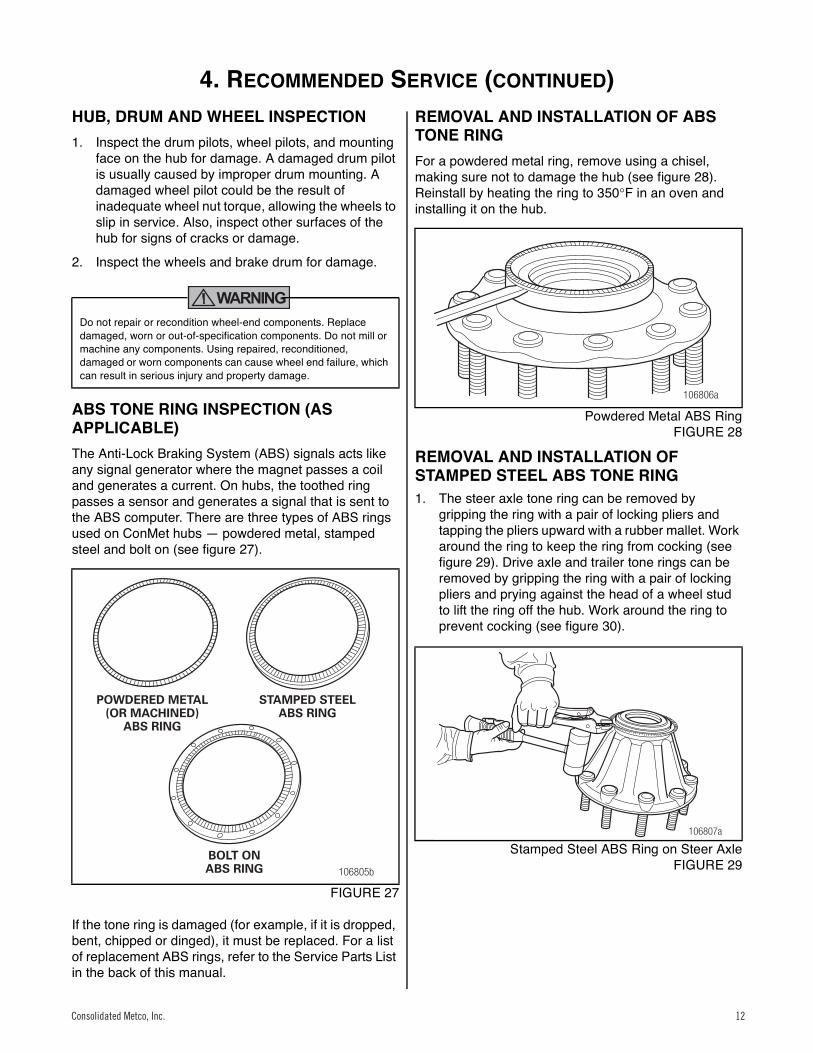
ABS TONE RING INSPECTION (AS APPLICABLE)The Anti-Lock Braking System (ABS) signals acts like any signal generator where the magnet passes a coil and generates a current. On hubs, the toothed ring passes a sensor and generates a signal that is sent to the ABS computer. There are three types of ABS rings used on ConMet hubs — powdered metal, stamped steel and bolt on (see figure 27).25
FIGURE 27
If the tone ring is damaged (for example, if it is dropped, bent, chipped or dinged), it must be replaced. For a list of replacement ABS rings, refer to the Service Parts List in the back of this manual.
REMOVAL AND INSTALLATION OF ABS TONE RINGFor a powdered metal ring, remove using a chisel, making sure not to damage the hub (see figure 28). Reinstall by heating the ring to 350°F in an oven and installing it on the hub.26
Powdered Metal ABS RingFIGURE 28
REMOVAL AND INSTALLATION OF STAMPED STEEL ABS TONE RING1. The steer axle tone ring can be removed by
gripping the ring with a pair of locking pliers and tapping the pliers upward with a rubber mallet. Work around the ring to keep the ring from cocking (see figure 29). Drive axle and trailer tone rings can be removed by gripping the ring with a pair of locking pliers and prying against the head of a wheel stud to lift the ring off the hub. Work around the ring to prevent cocking (see figure 30).
27
Stamped Steel ABS Ring on Steer AxleFIGURE 29
Do not repair or recondition wheel-end components. Replace damaged, worn or out-of-specification components. Do not mill or machine any components. Using repaired, reconditioned, damaged or worn components can cause wheel end failure, which can result in serious injury and property damage.
106805b
POWDERED METAL(OR MACHINED)
ABS RING
STAMPED STEELABS RING
BOLT ONABS RING
106806a
106807a
Consolidated Metco, Inc. 12Consolidated Metco, Inc. 12
4. RECOMMENDED SERVICE (CONTINUED)
Consolidated Metco, Inc. 13
28
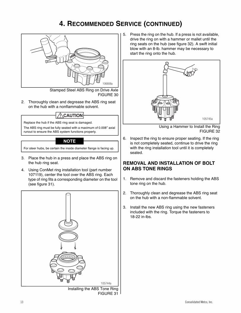
Stamped Steel ABS Ring on Drive AxleFIGURE 30
2. Thoroughly clean and degrease the ABS ring seat on the hub with a nonflammable solvent.
3. Place the hub in a press and place the ABS ring on the hub ring seat.
4. Using ConMet ring installation tool (part number 107119), center the tool over the ABS ring. Each type of ring fits a corresponding diameter on the tool (see figure 31).
29
Installing the ABS Tone RingFIGURE 31
5. Press the ring on the hub. If a press is not available, drive the ring on with a hammer or mallet until the ring seats on the hub (see figure 32). A swift initial blow with an 8-lb. hammer may be necessary to start the ring onto the hub.
30
Using a Hammer to Install the RingFIGURE 32
6. Inspect the ring to ensure proper seating. If the ring is not completely seated, continue to drive the ring with the ring installation tool until it is completely seated.
REMOVAL AND INSTALLATION OF BOLT ON ABS TONE RINGS
1. Remove and discard the fasteners holding the ABS tone ring on the hub.
2. Thoroughly clean and degrease the ABS ring seat on the hub with a non-flammable solvent.
3. Install the new ABS ring using the new fasteners included with the ring. Torque the fasteners to 18-22 in-lbs.
Replace the hub if the ABS ring seat is damaged.The ABS ring must be fully seated with a maximum of 0.008″ axial runout to ensure the ABS system functions properly.
For steer hubs, be certain the inside diameter flange is facing up.
106808a
105744a
105745a
Consolidated Metco, Inc.13 Consolidated Metco, Inc.13

5. REASSEMBLY – PRESET WHEEL HUBS
14 Consolidated Metco, Inc.
Reassembly
1. Place the hub, seal end up, on a clean work bench surface.
2. For steer hubs, install the tubular bearing spacer with the tapered end down (see figure 33).
31
Bearing Cone Assembly for Steer HubFIGURE 33
3. Lubricate the inner bearing cone with the same lubricant as will be used in the hub and install it into the inner bearing cup (see figure 34).
32
Bearing Cone Assembly for Drive HubFIGURE 34
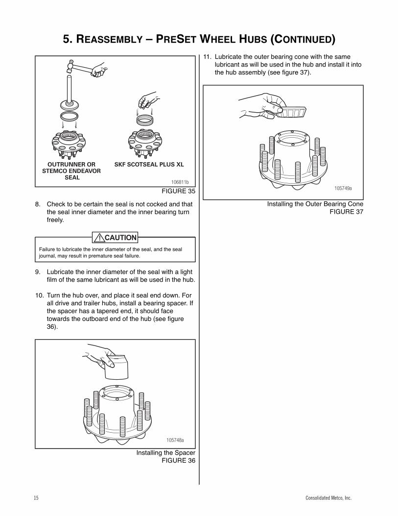
4. When installing the SKF or Outrunner wheel seal, lubricate the seal outer diameter and the hub seal bore with the same lubricant as will be used in the hub. The Stemco Endeavor seal is installed dry and should not be lubricated.
5. Position the seal into the hub bore.
6. When installing the Outrunner or Stemco Endeavor seal, tap the adapter plate of the installation tool around the outer edge to position the seal. Drive the wheel seal into place (see figure 35). Once the tool bottoms out, the seal is installed correctly.
7. When installing the SKF Scotseal Plus XL, press the seal evenly into the bore by hand (see figure 35). If additional force is needed, use a flat plate and a small mallet to install the seal.
When using an oil bath system, do not pack the bearing with grease. Grease will prevent the proper circulation of axle lubricant and can cause premature wheel seal and bearing failure.
If you are working on a drive or trailer hub, go to step 3. If you are working on a steer hub, proceed as follows.
106809a
106810a
The seal must be replaced every time the hub is removed from the spindle.Do not apply any gasket sealant to the seal outer or inner diameter.Always use the seal installation tool specified by the seal manufacturer. Using an improper tool can distort or damage the seal and cause premature seal failure.If using the Outrunner wheel seal, place the seal with the “air side” facing the adapter plate of the installation tool.If using the SKF Scotseal Plus XL wheel seal, no special installation tools are required.If using the Stemco Endeavor seal, be sure to use the Stemco installation tool.
The Outrunner and Stemco Endeavor seals require the proper tool for installation. Refer to the Service Parts List on page 20 of the manual to identify the correct installation tool.
Consolidated Metco, Inc. 14Consolidated Metco, Inc. 14
5. REASSEMBLY – PRESET WHEEL HUBS (CONTINUED)
Consolidated Metco, Inc. 15
33
FIGURE 35
8. Check to be certain the seal is not cocked and that the seal inner diameter and the inner bearing turn freely.
9. Lubricate the inner diameter of the seal with a light film of the same lubricant as will be used in the hub.
10. Turn the hub over, and place it seal end down. For all drive and trailer hubs, install a bearing spacer. If the spacer has a tapered end, it should face towards the outboard end of the hub (see figure 36).
34
Installing the SpacerFIGURE 36
11. Lubricate the outer bearing cone with the same lubricant as will be used in the hub and install it into the hub assembly (see figure 37).
35
Installing the Outer Bearing ConeFIGURE 37
Failure to lubricate the inner diameter of the seal, and the seal journal, may result in premature seal failure.
106811b
OUTRUNNER ORSTEMCO ENDEAVOR
SEAL
SKF SCOTSEAL PLUS XL
105748a
105749a
Consolidated Metco, Inc.15 Consolidated Metco, Inc.15
5. REASSEMBLY – PRESET PLUS WHEEL HUBS
16 Consolidated Metco, Inc.
1. For proper reassembly of the bearings, bearing spacer and wheel seal in PreSet Plus hubs, follow the procedures outlined in "Reassembly of PreSet Wheel Hubs."
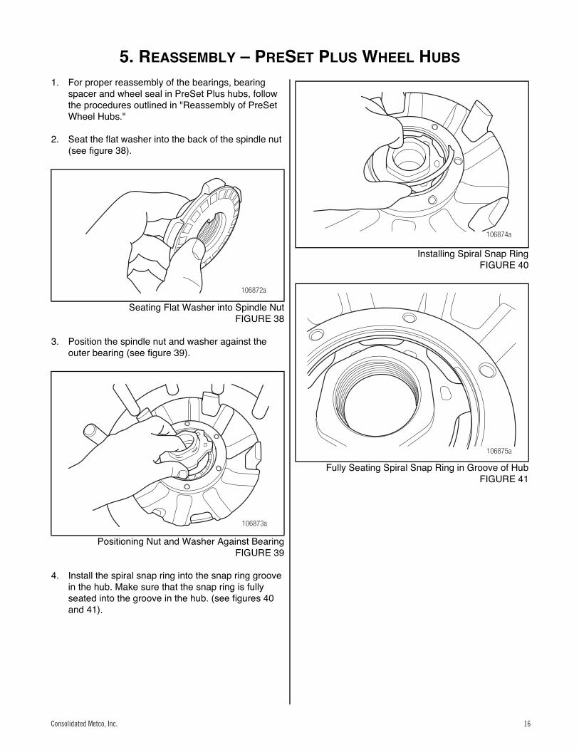
2. Seat the flat washer into the back of the spindle nut (see figure 38).
36
Seating Flat Washer into Spindle NutFIGURE 38
3. Position the spindle nut and washer against the outer bearing (see figure 39).
37
Positioning Nut and Washer Against BearingFIGURE 39
4. Install the spiral snap ring into the snap ring groove in the hub. Make sure that the snap ring is fully seated into the groove in the hub. (see figures 40 and 41).
38
Installing Spiral Snap RingFIGURE 40
39
Fully Seating Spiral Snap Ring in Groove of HubFIGURE 41
106872a
106873a
106874a
106875a
Consolidated Metco, Inc. 16Consolidated Metco, Inc. 16
6. REINSTALLATION
Consolidated Metco, Inc. 17
Reinstallation
IDENTIFYING HUB TO BE INSTALLED
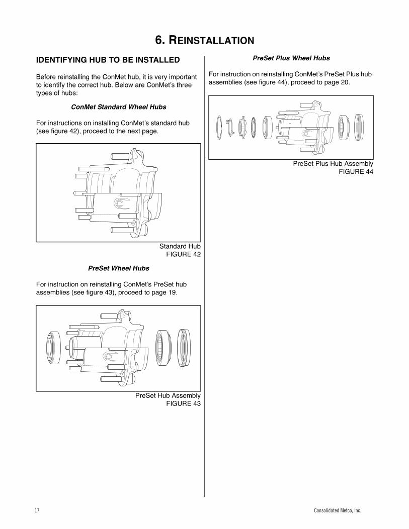
Before reinstalling the ConMet hub, it is very important to identify the correct hub. Below are ConMetʼs three types of hubs:
ConMet Standard Wheel Hubs
For instructions on installing ConMetʼs standard hub (see figure 42), proceed to the next page.40
Standard HubFIGURE 42
PreSet Wheel Hubs
For instruction on reinstalling ConMetʼs PreSet hub assemblies (see figure 43), proceed to page 19.41
PreSet Hub AssemblyFIGURE 43
PreSet Plus Wheel Hubs
For instruction on reinstalling ConMetʼs PreSet Plus hub assemblies (see figure 44), proceed to page 20.42
PreSet Plus Hub AssemblyFIGURE 44
Consolidated Metco, Inc.17 Consolidated Metco, Inc.17
6. REINSTALLATION – CONMET STANDARD WHEEL HUBS
18 Consolidated Metco, Inc.
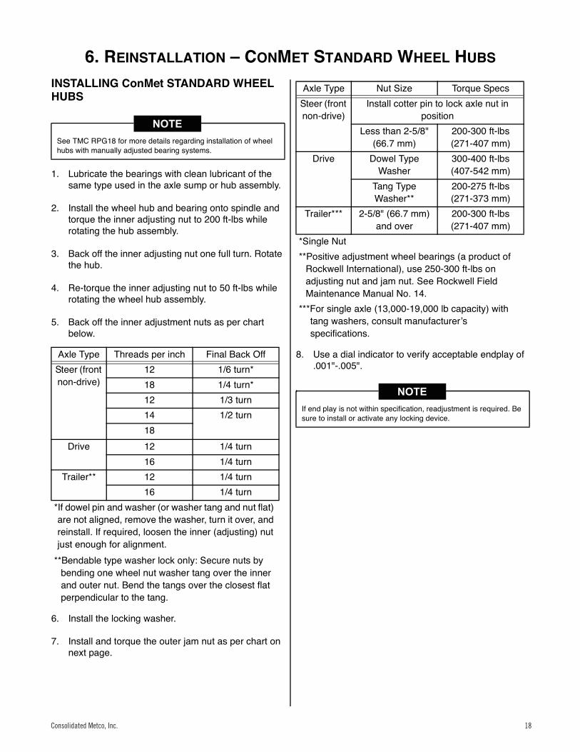
INSTALLING ConMet STANDARD WHEEL HUBS
1. Lubricate the bearings with clean lubricant of the same type used in the axle sump or hub assembly.
2. Install the wheel hub and bearing onto spindle and torque the inner adjusting nut to 200 ft-lbs while rotating the hub assembly.
3. Back off the inner adjusting nut one full turn. Rotate the hub.
4. Re-torque the inner adjusting nut to 50 ft-lbs while rotating the wheel hub assembly.
5. Back off the inner adjustment nuts as per chart below.
6. Install the locking washer.
7. Install and torque the outer jam nut as per chart on next page.
8. Use a dial indicator to verify acceptable endplay of .001"-.005".
See TMC RPG18 for more details regarding installation of wheel hubs with manually adjusted bearing systems.
Axle Type Threads per inch Final Back OffSteer (front non-drive)
12 1/6 turn*18 1/4 turn*12 1/3 turn14 1/2 turn18
Drive 12 1/4 turn16 1/4 turn
Trailer** 12 1/4 turn16 1/4 turn
*If dowel pin and washer (or washer tang and nut flat) are not aligned, remove the washer, turn it over, and reinstall. If required, loosen the inner (adjusting) nut just enough for alignment.
**Bendable type washer lock only: Secure nuts by bending one wheel nut washer tang over the inner and outer nut. Bend the tangs over the closest flat perpendicular to the tang.
Axle Type Nut Size Torque SpecsSteer (front non-drive)
Install cotter pin to lock axle nut in position
Less than 2-5/8" (66.7 mm)
200-300 ft-lbs (271-407 mm)
Drive Dowel Type Washer
300-400 ft-lbs (407-542 mm)
Tang Type Washer**
200-275 ft-lbs (271-373 mm)
Trailer*** 2-5/8" (66.7 mm) and over
200-300 ft-lbs (271-407 mm)
*Single Nut**Positive adjustment wheel bearings (a product of
Rockwell International), use 250-300 ft-lbs on adjusting nut and jam nut. See Rockwell Field Maintenance Manual No. 14.
***For single axle (13,000-19,000 lb capacity) with tang washers, consult manufacturerʼs specifications.
If end play is not within specification, readjustment is required. Be sure to install or activate any locking device.
Consolidated Metco, Inc. 18Consolidated Metco, Inc. 18
6. REINSTALLATION – PRESET WHEEL HUBS
Consolidated Metco, Inc. 19
INSTALLING THE PreSet WHEEL HUB ASSEMBLY
Spindle Preparation
1. Clean the spindle to remove any lubricant, corrosion prevention coating, foreign material, or surface rust that may be present.
2. Lubricate the bearing journals on the spindle, or the inside diameter of the bearing cones with Grade 2 grease or the lubricant that will be used in the wheel end. Do not coat the seal journal on the spindle.
3. Lubricate the inside diameter of the seal with the same lubricant that will be used in the wheel end.
Mounting the Hub
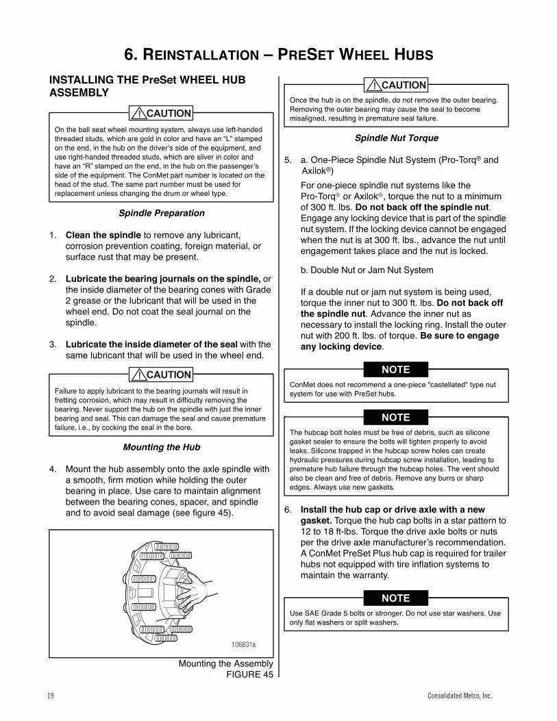
4. Mount the hub assembly onto the axle spindle with a smooth, firm motion while holding the outer bearing in place. Use care to maintain alignment between the bearing cones, spacer, and spindle and to avoid seal damage (see figure 45).
43
Mounting the AssemblyFIGURE 45
Spindle Nut Torque
5. a. One-Piece Spindle Nut System (Pro-Torq® and Axilok®)For one-piece spindle nut systems like the Pro-Torq or Axilok, torque the nut to a minimum of 300 ft. lbs. Do not back off the spindle nut.Engage any locking device that is part of the spindle nut system. If the locking device cannot be engaged when the nut is at 300 ft. lbs., advance the nut until engagement takes place and the nut is locked.
b. Double Nut or Jam Nut System
If a double nut or jam nut system is being used, torque the inner nut to 300 ft. lbs. Do not back off the spindle nut. Advance the inner nut as necessary to install the locking ring. Install the outer nut with 200 ft. lbs. of torque. Be sure to engage any locking device.
6. Install the hub cap or drive axle with a new gasket. Torque the hub cap bolts in a star pattern to 12 to 18 ft-lbs. Torque the drive axle bolts or nuts per the drive axle manufacturerʼs recommendation. A ConMet PreSet Plus hub cap is required for trailer hubs not equipped with tire inflation systems to maintain the warranty.
On the ball seat wheel mounting system, always use left-handed threaded studs, which are gold in color and have an “L” stamped on the end, in the hub on the driverʼs side of the equipment, and use right-handed threaded studs, which are silver in color and have an “R” stamped on the end, in the hub on the passengerʼs side of the equipment. The ConMet part number is located on the head of the stud. The same part number must be used for replacement unless changing the drum or wheel type.
Failure to apply lubricant to the bearing journals will result in fretting corrosion, which may result in difficulty removing the bearing. Never support the hub on the spindle with just the inner bearing and seal. This can damage the seal and cause premature failure, i.e., by cocking the seal in the bore.
106831a
Once the hub is on the spindle, do not remove the outer bearing. Removing the outer bearing may cause the seal to become misaligned, resulting in premature seal failure.
ConMet does not recommend a one-piece "castellated" type nut system for use with PreSet hubs.
The hubcap bolt holes must be free of debris, such as silicone gasket sealer to ensure the bolts will tighten properly to avoid leaks. Silicone trapped in the hubcap screw holes can create hydraulic pressures during hubcap screw installation, leading to premature hub failure through the hubcap holes. The vent should also be clean and free of debris. Remove any burrs or sharp edges. Always use new gaskets.
Use SAE Grade 5 bolts or stronger. Do not use star washers. Use only flat washers or split washers.
Consolidated Metco, Inc.19 Consolidated Metco, Inc.19

6. REINSTALLATION – PRESET PLUS WHEEL HUBS
20 Consolidated Metco, Inc.
INSTALLING THE PreSet Plus WHEEL HUB ASSEMBLY
WARNING
1. Clean the spindle to remove any lubricant, corrosion prevention coating, foreign material, or surface rust that may be present.
2. Lubricate the bearing journals on the spindle, or the inside diameter of the bearing cones with Grade 2 grease or the lubricant that will be used in the wheel end. Do not coat the seal journal on the spindle.
3. Lubricate the inside diameter of the seal with the same lubricant that will be used in the wheel end.
4. If present, remove the red locking snap ring from the spindle nut. Verify that the bearing spacer is in proper alignment. Align the key or flat on the washer with the keyway or flat on the spindle as the hub is placed onto the spindle. Use a smooth firm motion and place the hub onto the spindle.When the threads on the nut engage the threads on the spindle, rotate the nut in a clockwise direction to fully engage the threads.
5. Torque the spindle nut to the following torque values:
Steer Hub – Torque the spindle nut to 300 ft-lbs while rotating the hub. DO NOT BACK OFF THE SPINDLE NUT.
Drive Hub or Trailer Hub – Torque the spindle nut to 500 ft-lbs while rotating the hub. DO NOT BACK OFF THE SPINDLE NUT.
Socket Sizes for PreSet Plus Spindle Nuts
6. Visually examine the three holes in the face of the spindle nut. One of the holes will line up with the holes in the inner washer. Install the tab of the red locking snap ring through the hole in the nut and washer that are aligned. Spread the locking ring, push it over the spindle nut and in to the machined grooves in the spindle nut. Use caution not to bend the locking ring permanently. If the locking ring is damaged or bent, replace it with a new one.
7. Install the hub cap or drive axle with a new gasket. Torque the hub cap bolts in a star pattern to 12 to 18 ft-lbs. Torque the drive axle bolts or nuts per the drive axle manufacturerʼs recommendation. A ConMet PreSet Plus hub cap is required for trailer hubs not equipped with tire inflation systems to maintain the warranty.
Failure to fill the hub with the correct amount of lubricant can cause premature failure of the PreSet Plus hub assembly, which, if not avoided, could result in death or serious injury.
Use the proper hubcap for the type of lubricant intended to be used.
FFFlat
FFKeyway FL R TN TP
Socket Size
(6 Point)2" 2" 2.75" 3.75" 3.125" 4"
Consolidated Metco, Inc. 20Consolidated Metco, Inc. 20
7. LUBRICATION
Consolidated Metco, Inc. 21
Lubrication
DRIVE HUB LUBRICATION
Drive hubs can be lubricated by installing one quart of oil through the fill plug in the barrel of the hub.
If no fill plug is present, the drive hub can be lubricated by lifting the opposite side of the axle 8" to allow the lubricant to run down the axle housing and into the hub assembly. Elevate the axle for two minutes to allow the lubricant time to fill the hub. Repeat the process for the opposite side of the vehicle. The rear axle carrier should be filled to the proper level to ensure adequate lubricant is available to fill the entire hub. Refill the carrier to the proper level after this procedure is completed.
STEER AND TRAILER HUBS WITH OIL LUBRICANT
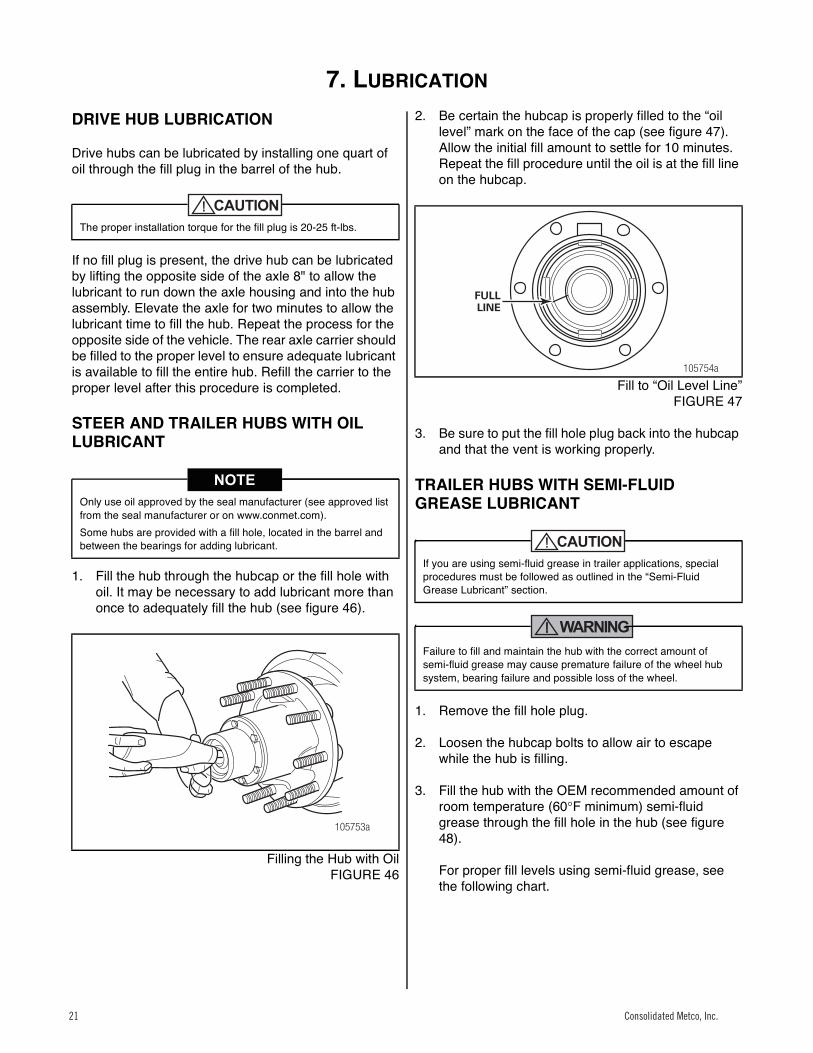
1. Fill the hub through the hubcap or the fill hole with oil. It may be necessary to add lubricant more than once to adequately fill the hub (see figure 46).
44
Filling the Hub with OilFIGURE 46
2. Be certain the hubcap is properly filled to the “oil level” mark on the face of the cap (see figure 47). Allow the initial fill amount to settle for 10 minutes. Repeat the fill procedure until the oil is at the fill line on the hubcap.
45
Fill to “Oil Level Line”FIGURE 47
3. Be sure to put the fill hole plug back into the hubcap and that the vent is working properly.
TRAILER HUBS WITH SEMI-FLUID GREASE LUBRICANT
WARNING
1. Remove the fill hole plug.
2. Loosen the hubcap bolts to allow air to escape while the hub is filling.
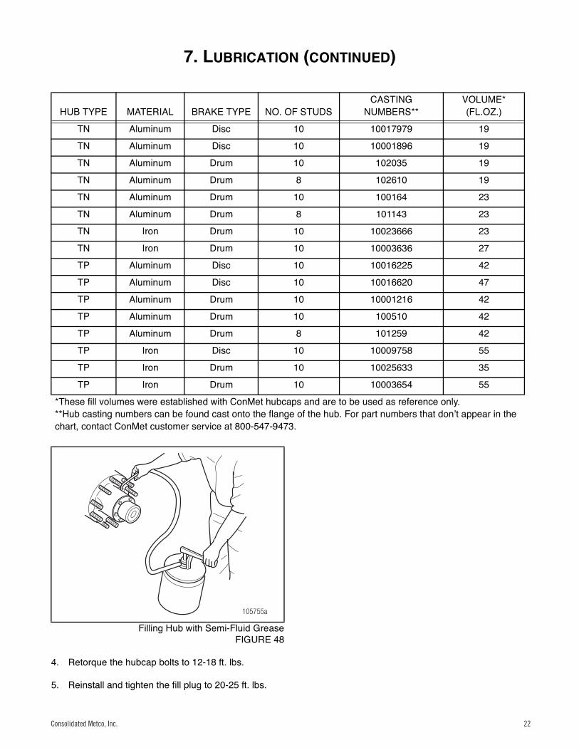
3. Fill the hub with the OEM recommended amount of room temperature (60°F minimum) semi-fluid grease through the fill hole in the hub (see figure 48).
For proper fill levels using semi-fluid grease, see the following chart.
The proper installation torque for the fill plug is 20-25 ft-lbs.
Only use oil approved by the seal manufacturer (see approved list from the seal manufacturer or on www.conmet.com).Some hubs are provided with a fill hole, located in the barrel and between the bearings for adding lubricant.
105753a
If you are using semi-fluid grease in trailer applications, special procedures must be followed as outlined in the “Semi-Fluid Grease Lubricant” section.
Failure to fill and maintain the hub with the correct amount of semi-fluid grease may cause premature failure of the wheel hub system, bearing failure and possible loss of the wheel.
105754a
FULLLINE
Consolidated Metco, Inc.21 Consolidated Metco, Inc.21
7. LUBRICATION (CONTINUED)
Consolidated Metco, Inc. 22
46
Filling Hub with Semi-Fluid GreaseFIGURE 48
4. Retorque the hubcap bolts to 12-18 ft. lbs.
5. Reinstall and tighten the fill plug to 20-25 ft. lbs.
HUB TYPE MATERIAL BRAKE TYPE NO. OF STUDSCASTING
NUMBERS**VOLUME* (FL.OZ.)
TN Aluminum Disc 10 10017979 19
TN Aluminum Disc 10 10001896 19
TN Aluminum Drum 10 102035 19
TN Aluminum Drum 8 102610 19
TN Aluminum Drum 10 100164 23
TN Aluminum Drum 8 101143 23
TN Iron Drum 10 10023666 23
TN Iron Drum 10 10003636 27
TP Aluminum Disc 10 10016225 42
TP Aluminum Disc 10 10016620 47
TP Aluminum Drum 10 10001216 42
TP Aluminum Drum 10 100510 42
TP Aluminum Drum 8 101259 42
TP Iron Disc 10 10009758 55
TP Iron Drum 10 10025633 35
TP Iron Drum 10 10003654 55
*These fill volumes were established with ConMet hubcaps and are to be used as reference only.**Hub casting numbers can be found cast onto the flange of the hub. For part numbers that donʼt appear in the chart, contact ConMet customer service at 800-547-9473.
105755a
Consolidated Metco, Inc. 22Consolidated Metco, Inc. 22
8. BRAKE DRUM AND WHEEL INSTALLATION
Consolidated Metco, Inc. 23
Brake Drum and Wheel Installation
Hub Pilot Wheel Mounting System
WARNING
47
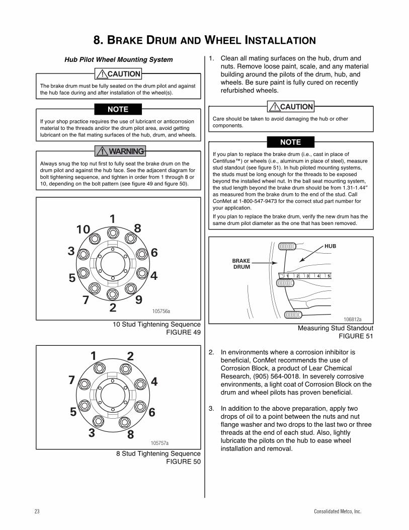
10 Stud Tightening SequenceFIGURE 49
48
8 Stud Tightening SequenceFIGURE 50
1. Clean all mating surfaces on the hub, drum and nuts. Remove loose paint, scale, and any material building around the pilots of the drum, hub, and wheels. Be sure paint is fully cured on recently refurbished wheels.
49
Measuring Stud StandoutFIGURE 51
2. In environments where a corrosion inhibitor is beneficial, ConMet recommends the use of Corrosion Block, a product of Lear Chemical Research, (905) 564-0018. In severely corrosive environments, a light coat of Corrosion Block on the drum and wheel pilots has proven beneficial.
3. In addition to the above preparation, apply two drops of oil to a point between the nuts and nut flange washer and two drops to the last two or three threads at the end of each stud. Also, lightly lubricate the pilots on the hub to ease wheel installation and removal.
The brake drum must be fully seated on the drum pilot and against the hub face during and after installation of the wheel(s).
If your shop practice requires the use of lubricant or anticorrosion material to the threads and/or the drum pilot area, avoid getting lubricant on the flat mating surfaces of the hub, drum, and wheels.
Always snug the top nut first to fully seat the brake drum on the drum pilot and against the hub face. See the adjacent diagram for bolt tightening sequence, and tighten in order from 1 through 8 or 10, depending on the bolt pattern (see figure 49 and figure 50).
105756a
6
81
10
3
5 4
972
6
8
1
3
5
47
2
105757a
Care should be taken to avoid damaging the hub or other components.
If you plan to replace the brake drum (i.e., cast in place of Centifuse™) or wheels (i.e., aluminum in place of steel), measure stud standout (see figure 51). In hub piloted mounting systems, the studs must be long enough for the threads to be exposed beyond the installed wheel nut. In the ball seat mounting system, the stud length beyond the brake drum should be from 1.31-1.44″as measured from the brake drum to the end of the stud. Call ConMet at 1-800-547-9473 for the correct stud part number for your application.If you plan to replace the brake drum, verify the new drum has the same drum pilot diameter as the one that has been removed.
1 2 3 4 5
106812a
HUB
BRAKEDRUM
Consolidated Metco, Inc.23 Consolidated Metco, Inc.23

8. BRAKE DRUM AND WHEEL INSTALLATION (CONTINUED)
Consolidated Metco, Inc. 24
4. Before installation of brake drums and wheels that utilize the hub piloted system, rotate the hub so one of the wheel pilot bosses is at the top (12 oʼclock position) (see figure 52).
50
Rotating the HubFIGURE 52
5. Position the brake drum over the hub, so it seats on the drum pilot and against the hub face.
6. Place the wheel(s) into position. One or more nuts can be started in order to hold wheel(s) and drum into position.
7. Snug the top nut first. Apply 50 ft. lbs. torque to draw the brake drum up fully against the hub (see figure 53).
51
Reinstalling the WheelFIGURE 53
8. Install the remaining wheel nuts and using the sequence as shown, torque all the nuts to 50 ft. lbs., then retorque to 450-500 ft. lbs. (see figure 49 and figure 50). The last nut rotation must be with a calibrated torquing device.
9. Inspect the brake and wheel installation by checking the seating of the wheel(s) and drum at the pilots, and by turning the wheel(s) and checking for any irregularity.
Ball Seat Wheel Mounting System
1. Clean all mating surfaces on the hub, drum, wheels and nuts. Remove loose paint, scale, and any material building around the pilots of the drum, hub, and wheels. Be sure paint is fully cured on recently refurbished wheels.
Do not get lubricant on the mounting face of the drum or wheel. Failure to clean lubricant from these surfaces may result in decreased clamping load.
105758a
WHEEL PILOT BOSS
106824b
When torquing wheel nuts, the temperature of all the wheel end components should be as close as possible to the midpoint of the expected operating range. For example, if the hub will operate between 0°F and 150°F, 75°F is a good temperature to torque at. Room temperature is often a close approximation of the midpoint temperature. This recommendation is due to the differences in the coefficient of thermal expansion for the various materials in the wheel end including the hub, studs, wheel and brake drum. If the wheel nuts are torqued at temperatures well below the midpoint, when the system warms up, the studs may become overstressed. This could cause the studs to be permanently stretched, leading to nut loosening or damage to the wheel or hub. If the torque is applied at elevated temperatures, the system may become loose and lose clamp at lower temperatures, resulting in wheel damage and broken wheel studs. If the nuts must be torqued at extreme temperatures, the nut torque should be readjusted when the temperature is in the desired range. See also TMC RP250 "Effects of Extreme Temperatures on Wheel Torque and Clamp Load".
Use the appropriate nuts with the above technique to install the front and outer dual wheels. Follow your shop practice to locate the valve stems.
Excessive or inadequate wheel nut torque can cause a failure of the wheel mounting system and a wheel separation resulting in severe personal injury or death and property damage. Always use a device that measures the torque being applied. After the first 50-100 miles, retorque all the nuts to 450-500 ft. lbs. Loosen the outer nuts to retorque the inner nuts.
Consolidated Metco, Inc. 24Consolidated Metco, Inc. 24
8. BRAKE DRUM AND WHEEL INSTALLATION (CONTINUED)
25 Consolidated Metco, Inc.
52
Stud StandoutFIGURE 54
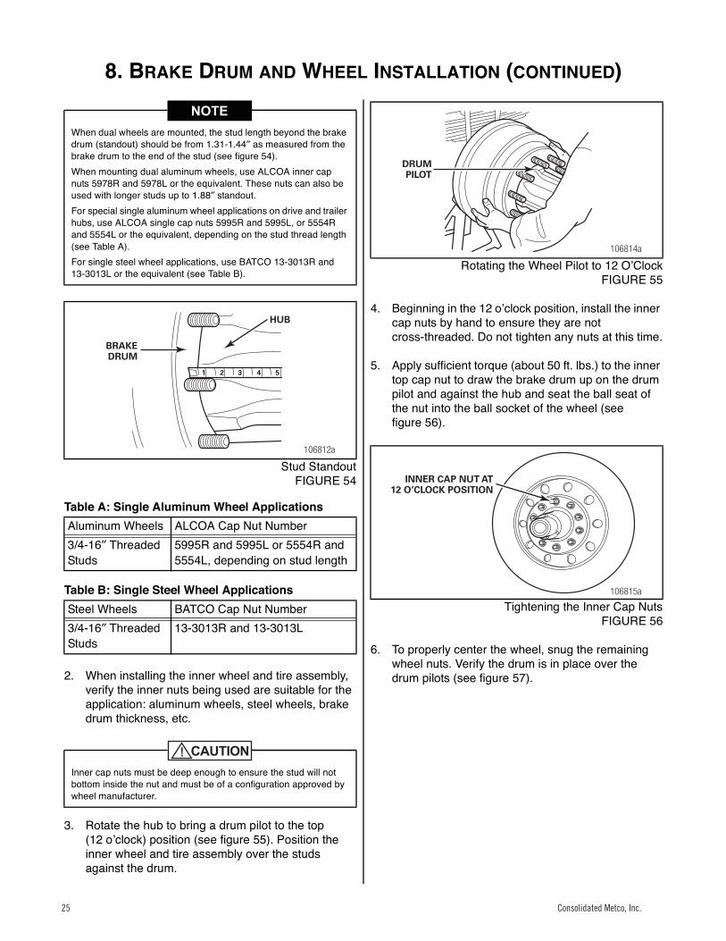
Table A: Single Aluminum Wheel Applications
Table B: Single Steel Wheel Applications
2. When installing the inner wheel and tire assembly, verify the inner nuts being used are suitable for the application: aluminum wheels, steel wheels, brake drum thickness, etc.
3. Rotate the hub to bring a drum pilot to the top (12 oʼclock) position (see figure 55). Position the inner wheel and tire assembly over the studs against the drum.
53
Rotating the Wheel Pilot to 12 OʼClockFIGURE 55
4. Beginning in the 12 oʼclock position, install the inner cap nuts by hand to ensure they are not cross-threaded. Do not tighten any nuts at this time.
5. Apply sufficient torque (about 50 ft. lbs.) to the inner top cap nut to draw the brake drum up on the drum pilot and against the hub and seat the ball seat of the nut into the ball socket of the wheel (see figure 56).
54
Tightening the Inner Cap NutsFIGURE 56
6. To properly center the wheel, snug the remaining wheel nuts. Verify the drum is in place over the drum pilots (see figure 57).
When dual wheels are mounted, the stud length beyond the brake drum (standout) should be from 1.31-1.44″ as measured from the brake drum to the end of the stud (see figure 54).When mounting dual aluminum wheels, use ALCOA inner cap nuts 5978R and 5978L or the equivalent. These nuts can also be used with longer studs up to 1.88″ standout.For special single aluminum wheel applications on drive and trailer hubs, use ALCOA single cap nuts 5995R and 5995L, or 5554R and 5554L or the equivalent, depending on the stud thread length (see Table A).For single steel wheel applications, use BATCO 13-3013R and 13-3013L or the equivalent (see Table B).
Aluminum Wheels ALCOA Cap Nut Number3/4-16″ Threaded Studs
5995R and 5995L or 5554R and 5554L, depending on stud length
Steel Wheels BATCO Cap Nut Number3/4-16″ Threaded Studs
13-3013R and 13-3013L
Inner cap nuts must be deep enough to ensure the stud will not bottom inside the nut and must be of a configuration approved by wheel manufacturer.
1 2 3 4 5
106812a
HUB
BRAKEDRUM
106814a
DRUMPILOT
106815a
INNER CAP NUT AT12 O’CLOCK POSITION
Consolidated Metco, Inc.25 Consolidated Metco, Inc.25

8. BRAKE DRUM AND WHEEL INSTALLATION (CONTINUED)
Consolidated Metco, Inc. 26
55
10 Stud Tightening SequenceFIGURE 57
7. Starting with the top nut first and using a staggered pattern, torque the inner wheel nuts in stages to 450-500 ft. lbs. (see figure 58). The last nut rotation must be with a calibrated torquing device.
56
Torquing the Inner Wheel NutsFIGURE 58
8. Install the outer wheel and nuts and tighten to 450-500 ft. lbs. (see figure 59). The last nut rotation must be with a calibrated torque device.
57
Torquing the Outer Wheel NutsFIGURE 59
9. Inspect the brake and wheel installation by checking the seating of the wheel(s) and drum at the pilots and by turning the wheel(s) and check for any irregularity.
Use the appropriate nuts with the above technique to install the front and outer dual wheels. Follow your shop practice to locate the valve stems.
105756a
6
81
10
3
5 4
972
106824b
Excessive or inadequate wheel nut torque can cause a failure of the wheel mounting system and a wheel separation resulting in severe personal injury or death and property damage. Always use a device that measures the torque being applied. After the first 50-100 miles, retorque all the nuts to 450-500 ft. lbs. Loosen the outer nuts to retorque the inner nuts.
106824b
Consolidated Metco, Inc. 26Consolidated Metco, Inc. 26

SERVICE PARTS LIST
27 Consolidated Metco, Inc.
Service Parts List
Axle Designations
Approved PreSet Oil Seals — Cross Reference
Approved Trailer Hub Caps
Seal Installation Tools (SKF Scotseal Plus XL is hand installable)
Designation Typical Axle Rating (lbs.) CommentsSteer AxleFC Steer 8,000 Medium dutyFF Steer 12,000-14,700 Standard linehaul axle. Comes in two spindle variations.
1. Flat locking feature with 12 threads/inch.2. Keyway locking feature with 18 threads/inch.
FL Steer 20,000 Vocational applicationsDrive AxleL-Drive 19,000 Medium dutyR-Drive 20,000-23,000 Standard linehaul axleTrailer AxleTN Trailer 22,500 Tapered spindleTP Trailer 25,000 Parallel spindle or "Propar"
Axle Designation ConMet Number SKF Scotseal Plus XL Timken Outrunner STEMCO EndeavorFC Steer 10037958 28759 N/A N/AFF Steer 10005430 35058 847 383-0336FL Steer 10008722 43761 N/A N/AL-Drive 10020083 38776 N/A N/AR-Drive 10005431 47691 861 393-0373TN Trailer 10023849 46300 859 373-0343TP Trailer 10023847 42627 851 373-0323
Axle Designation Type of Lubricant PreSet Hubs PreSet Plus HubsTN Trailer Semi-Fluid Grease 10018622 10036694TP Trailer Semi-Fluid Grease 10018621 10036693TN Trailer Oil 106819 10036692TP Trailer Oil 106870 10036691
Outrunner Stemco EndeavorAxle Designation Bearing Centering Tool Adapter Plate Universal Tool Handle Fleet Hub Tool Bearing GuideFC Steer N/A N/A N/A N/A N/AFF Steer BCT-6 847T 551-0001 551-5346 570-0020FL Steer N/A N/A 551-0001 551-5327 570-0022L-Drive BCT-10 849T N/A N/A N/AR-Drive BCT-15 861T 551-0001 551-5320 570-0028TN Trailer BCT-13 859T 551-0001 551-5412 570-0026TP Trailer BCT-12 851T 551-0001 551-5401 570-0025
Consolidated Metco, Inc.27
AxleDesignation
ConMetPremium Seal
SKF Scotseal Plus XL FNOK Milemaker National 5-Star Gold
SKFNumber
ConMetNumber
FNOKNumber
ConMetNumber
NationalNumber
ConMetNumber
FC Steer N/A 28759 10037958 N/A N/A N/A N/AFF Steer 10080119 35058 10005430 44847 10045690 N/A N/AFL Steer 10080109 43761 10008722 N/A N/A N/A N/AL Drive N/A 38776 10020083 N/A N/A N/A N/AR Drive 10080124 47691 10005431 44861 10045689 N/A N/ATN Trailer 10080129 46300 10023849 N/A N/A 380025 10045271
Approved PreSet Oil Seals — Cross Reference
Consolidated Metco, Inc.27
SERVICE PARTS LIST (CONTINUED)
Consolidated Metco, Inc. 28
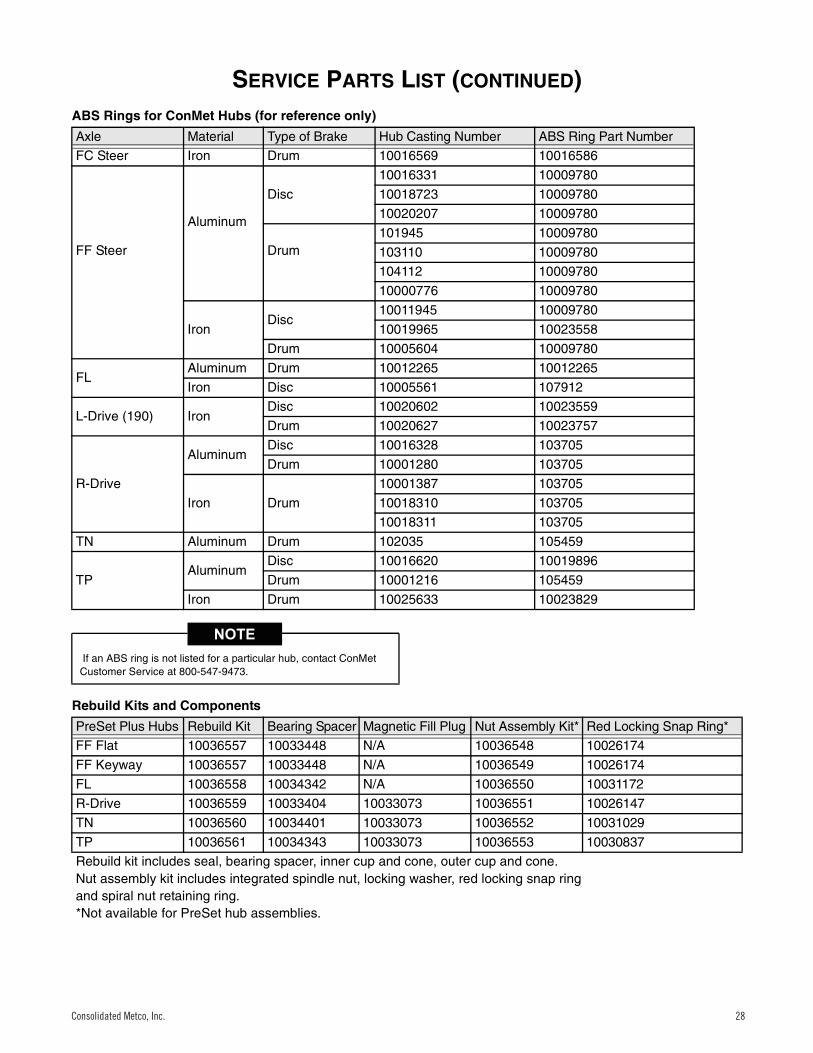
ABS Rings for ConMet Hubs (for reference only)
Rebuild Kits and Components
Axle Material Type of Brake Hub Casting Number ABS Ring Part Number
FC Steer Iron Drum 10016569 10016586
FF Steer
Aluminum
Disc
10016331 10009780
10018723 10009780
10020207 10009780
Drum101945 10009780
103110 10009780
104112 10009780
10000776 10009780
IronDisc
10011945 10009780
10019965 10023558
Drum 10005604 10009780
FLAluminum Drum 10012265 10012265
Iron Disc 10005561 107912
L-Drive (190) IronDisc 10020602 10023559
Drum 10020627 10023757
R-Drive
AluminumDisc 10016328 103705
Drum 10001280 103705
Iron Drum
10001387 103705
10018310 103705
10018311 103705
TN Aluminum Drum 102035 105459
TPAluminum
Disc 10016620 10019896
Drum 10001216 105459
Iron Drum 10025633 10023829
If an ABS ring is not listed for a particular hub, contact ConMet Customer Service at 800-547-9473.
PreSet Plus Hubs Rebuild Kit Bearing Spacer Magnetic Fill Plug Nut Assembly Kit* Red Locking Snap Ring*
FF Flat 10036557 10033448 N/A 10036548 10026174
FF Keyway 10036557 10033448 N/A 10036549 10026174
FL 10036558 10034342 N/A 10036550 10031172
R-Drive 10036559 10033404 10033073 10036551 10026147
TN 10036560 10034401 10033073 10036552 10031029
TP 10036561 10034343 10033073 10036553 10030837
Rebuild kit includes seal, bearing spacer, inner cup and cone, outer cup and cone.Nut assembly kit includes integrated spindle nut, locking washer, red locking snap ring and spiral nut retaining ring.*Not available for PreSet hub assemblies.
Consolidated Metco, Inc. 28Consolidated Metco, Inc. 28
SERVICE PARTS LIST (CONTINUED)
29 Consolidated Metco, Inc.
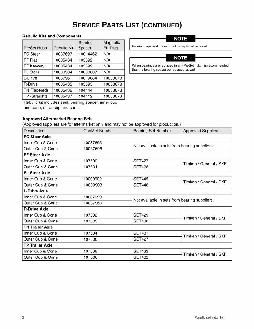
Rebuild Kits and Components
Approved Aftermarket Bearing Sets(Approved suppliers are for aftermarket only and may not be approved for production.)
PreSet Hubs Rebuild KitBearing Spacer
Magnetic Fill Plug
FC Steer 10037697 10014462 N/A
FF Flat 10005434 103592 N/A
FF Keyway 10005434 103592 N/A
FL Steer 10009904 10003807 N/A
L-Drive 10037961 10019884 10033073
R-Drive 10005435 103593 10033073
TN (Tapered) 10005436 104144 10033073
TP (Straight) 10005437 104412 10033073
Rebuild kit includes seal, bearing spacer, inner cup and cone, outer cup and cone.
Bearing cups and cones must be replaced as a set.
When bearings are replaced in any PreSet hub, it is recommended that the bearing spacer be replaced as well.
Description ConMet Number Bearing Set Number Approved Suppliers
FC Steer AxleInner Cup & Cone 10037695
Not available in sets from bearing suppliers.Outer Cup & Cone 10037696
FF Steer AxleInner Cup & Cone 107500 SET427
Timken / General / SKFOuter Cup & Cone 107501 SET428
FL Steer AxleInner Cup & Cone 10009902 SET445
Timken / General / SKFOuter Cup & Cone 10009903 SET446
L-Drive AxleInner Cup & Cone 10037959
Not available in sets from bearing suppliers.Outer Cup & Cone 10037960
R-Drive AxleInner Cup & Cone 107502 SET429
Timken / General / SKFOuter Cup & Cone 107503 SET430
TN Trailer AxleInner Cup & Cone 107504 SET431
Timken / General / SKFOuter Cup & Cone 107500 SET427
TP Trailer AxleInner Cup & Cone 107506 SET432
Timken / General / SKFOuter Cup & Cone 107506 SET432
Consolidated Metco, Inc.29 Consolidated Metco, Inc.29
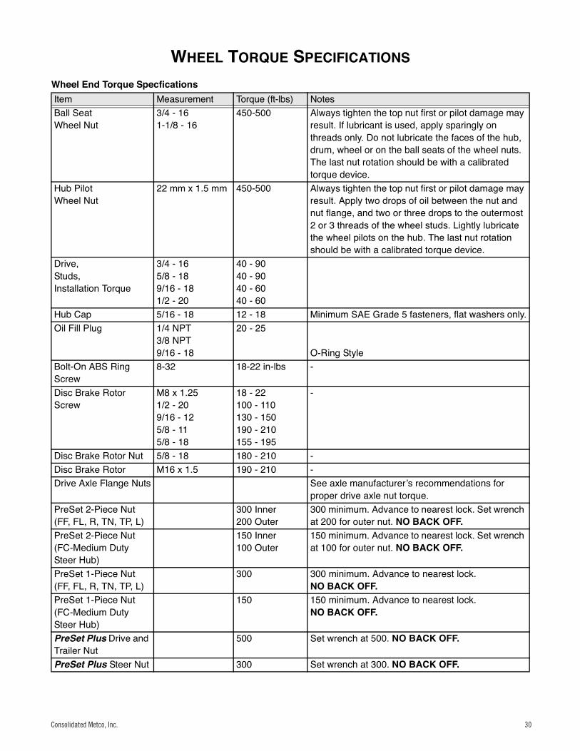
WHEEL TORQUE SPECIFICATIONS
30 Consolidated Metco, Inc.
Wheel Torque Specifications
Wheel End Torque SpecficationsItem Measurement Torque (ft-lbs) NotesBall SeatWheel Nut
3/4 - 161-1/8 - 16
450-500 Always tighten the top nut first or pilot damage may result. If lubricant is used, apply sparingly on threads only. Do not lubricate the faces of the hub, drum, wheel or on the ball seats of the wheel nuts. The last nut rotation should be with a calibrated torque device.
Hub PilotWheel Nut
22 mm x 1.5 mm 450-500 Always tighten the top nut first or pilot damage may result. Apply two drops of oil between the nut and nut flange, and two or three drops to the outermost 2 or 3 threads of the wheel studs. Lightly lubricate the wheel pilots on the hub. The last nut rotation should be with a calibrated torque device.
Drive,Studs,Installation Torque
3/4 - 165/8 - 189/16 - 181/2 - 20
40 - 9040 - 9040 - 6040 - 60
Hub Cap 5/16 - 18 12 - 18 Minimum SAE Grade 5 fasteners, flat washers only.Oil Fill Plug 1/4 NPT
3/8 NPT9/16 - 18
20 - 25
O-Ring StyleBolt-On ABS Ring Screw
8-32 18-22 in-lbs -
Disc Brake Rotor Screw
M8 x 1.251/2 - 209/16 - 125/8 - 115/8 - 18
18 - 22100 - 110130 - 150190 - 210155 - 195
-
Disc Brake Rotor Nut 5/8 - 18 180 - 210 -Disc Brake Rotor M16 x 1.5 190 - 210 -Drive Axle Flange Nuts See axle manufacturerʼs recommendations for
proper drive axle nut torque.PreSet 2-Piece Nut(FF, FL, R, TN, TP, L)
300 Inner200 Outer
300 minimum. Advance to nearest lock. Set wrench at 200 for outer nut. NO BACK OFF.
PreSet 2-Piece Nut(FC-Medium Duty Steer Hub)
150 Inner100 Outer
150 minimum. Advance to nearest lock. Set wrench at 100 for outer nut. NO BACK OFF.
PreSet 1-Piece Nut(FF, FL, R, TN, TP, L)
300 300 minimum. Advance to nearest lock.NO BACK OFF.
PreSet 1-Piece Nut(FC-Medium Duty Steer Hub)
150 150 minimum. Advance to nearest lock.NO BACK OFF.
PreSet Plus Drive and Trailer Nut
500 Set wrench at 500. NO BACK OFF.
PreSet Plus Steer Nut 300 Set wrench at 300. NO BACK OFF.
Consolidated Metco, Inc. 30Consolidated Metco, Inc. 30

Notes:
Consolidated Metco, Inc.31

Notes:
Consolidated Metco, Inc. 32
Consolidated Metco, Inc. 5701 SE Columbia Way, Vancouver, WA 98661 • (800) 547-9473 • www.conmet.com
Part No. 10041406 Rev A12-2013 Printed in the USA
Notes: