heliarc 250 ac square wave power sources - … - f15-999/heliarc...square wave power sources ... p/n...
TRANSCRIPT

F-15-047-AFebruary, 1995
Heliarc® 250 AC/DCSQUARE WAVE POWER SOURCES
NOTE: This manual is also suitable for use with L-TEC Heliarc 250 HF plus.
These INSTRUCTIONS are for experienced operators. If you are not fully familiar with the principles of operation andsafe practices for arc welding equipment, we urge you to read our booklet, "Precautions and Safe Practices for ArcWelding, Cutting, and Gouging", Form 52-529. Do NOT permit untrained persons to install, operate, or maintain thisequipment. Do NOT attempt to install or operate this equipment until you have read and fully understand theseinstructions. If you do not fully understand these instructions, contact your supplier for further information. Be sureto read the Safety Precautions (Section 1) before installing or operating this equipment.
Be sure this information reaches the operator.You can get extra copies through your supplier.
INSTRUCTION MANUAL
P/N 31310 - Heliarc 250 AC/DC w/power factorP/N 31300 - Heliarc 250 AC/DC w/o power factor

This equipment will perform in conformity with the description thereof contained in this manual andaccompanying labels and/or inserts when installed, operated, maintained and repaired in accordance with theinstructions provided. This equipment must be checked periodically. Defective equipment should not be used.Parts that are broken, missing, worn, distorted or contaminated should be replaced immediately. Should suchrepair or replacement become necessary, the manufacturer recommends that a telephone or written requestfor service advice be made to the Authorized Distributor from whom purchased.
This equipment or any of its parts should not be altered without the prior written approval of the manufac-turer. The user of this equipment shall have the sole responsibility for any malfunction which results fromimproper use, faulty maintenance, damage, improper repair or alteration by anyone other than the manufac-turer or a service facility designated by the manufacturer.
USER RESPONSIBILITY
2
2
WARNING: These Safety Precautions are foryour protection. They summarize precaution-ary information from the references listed inAdditional Safety Information section. Before
performing any installation or operating procedures, besure to read and follow the safety precautions listed belowas well as all other manuals, material safety data sheets,labels, etc. Failure to observe Safety Precautions can resultin injury or death.
1. Always wear safety glasses with side shields in any workarea, even if welding helmets, face shields, and gogglesare also required.
2. Use a face shield fitted with the correct filter and coverplates to protect your eyes, face, neck, and ears fromsparks and rays of the arc when operating or observingoperations. Warn bystanders not to watch the arc andnot to expose themselves to the rays of the electric-arcor hot metal.
3. Wear flameproof gauntlet type gloves, heavy long-sleeveshirt, cuffless trousers, high-topped shoes, and a weld-ing helmet or cap for hair protection, to protect againstarc rays and hot sparks or hot metal. A flameproof apronmay also be desirable as protection against radiatedheat and sparks.
4. Hot sparks or metal can lodge in rolled up sleeves,trouser cuffs, or pockets. Sleeves and collars should bekept buttoned, and open pockets eliminated from thefront of clothing
5. Protect other personnel from arc rays and hot sparkswith a suitable non-flammable partition or curtains.
6. Use goggles over safety glasses when chipping slag orgrinding. Chipped slag may be hot and can fly far.Bystanders should also wear goggles over safety glasses.
1. Remove all combustible materials well away from thework area or cover the materials with a protective non-flammable covering. Combustible materials include wood,cloth, sawdust, liquid and gas fuels, solvents, paints andcoatings, paper, etc.
2. Hot sparks or hot metal can fall through cracks orcrevices in floors or wall openings and cause a hiddensmoldering fire or fires on the floor below. Make certainthat such openings are protected from hot sparks andmetal.“
3. Do not weld, cut or perform other hot work until theworkpiece has been completely cleaned so that thereare no substances on the workpiece which might pro-duce flammable or toxic vapors. Do not do hot work onclosed containers. They may explode.
4. Have fire extinguishing equipment handy for instant use,such as a garden hose, water pail, sand bucket, orportable fire extinguisher. Be sure you are trained in itsuse.
SAFETY PRECAUTIONS
11/95
5. Do not use equipment beyond its ratings. For example,overloaded welding cable can overheat and create a firehazard.
6. After completing operations, inspect the work area tomake certain there are no hot sparks or hot metal whichcould cause a later fire. Use fire watchers when neces-sary.
7. For additional information, refer to NFPA Standard 51B,"Fire Prevention in Use of Cutting and Welding Pro-cesses", available from the National Fire Protection Asso-ciation, Batterymarch Park, Quincy, MA 02269.
1. Be sure the power source frame (chassis) is connectedto the ground system of the input power.
2. Connect the workpiece to a good electrical ground.3. Connect the work cable to the workpiece. A poor or
missing connection can expose you or others to a fatalshock.
4. Use well-maintained equipment. Replace worn or dam-aged cables.
5. Keep everything dry, including clothing, work area, cables,torch/electrode holder, and power source.
6. Make sure that all parts of your body are insulated fromwork and from ground.
7. Do not stand directly on metal or the earth while workingin tight quarters or a damp area; stand on dry boards oran insulating platform and wear rubber-soled shoes.
8. Put on dry, hole-free gloves before turning on the power.9. Turn off the power before removing your gloves.
10. Refer to ANSI/ASC Standard Z49.1 (listed on next page)for specific grounding recommendations. Do not mis-take the work lead for a ground cable.
1. Welders having pacemakers should consult their physi-cian before welding. EMF may interfere with some pace-makers.
2. Exposure to EMF may have other health effects which areunknown.
3. Welders should use the following procedures to minimizeexposure to EMF:A. Route the electrode and work cables together. Secure
them with tape when possible.B. Never coil the torch or work cable around your body.C. Do not place your body between the torch and work
cables. Route cables on the same side of your body.D. Connect the work cable to the workpiece as close as
possible to the area being welded.E. Keep welding power source and cables as far away
from your body as possible.
!
! !
ELECTRICAL SHOCK -- Contact withlive electrical parts and ground cancause severe injury or death. DO NOTuse AC welding current in damp areas,if movement is confined, or if there isdanger of falling.
ELECTRIC AND MAGNETIC FIELDS —May be dangerous. Electric current flow-ing through any conductor causes local-ized Electric and Magnetic Fields (EMF).Welding and cutting current creates EMFaround welding cables and welding ma-chines. Therefore:
FIRES AND EXPLOSIONS -- Heat fromflames and arcs can start fires. Hot slagor sparks can also cause fires and explo-sions. Therefore:
PROTECT YOURSELF AND OTHERS --Some welding, cutting, and gouging pro-cesses are noisy and require ear protec-tion. The arc, like the sun, emits ultravio-let (UV) and other radiation and can in-jure skin and eyes. Hot metal can cause
burns. Training in the proper use of the processes andequipment is essential to prevent accidents. Therefore:

3
1. Always provide adequate ventilation in the work area bynatural or mechanical means. Do not weld, cut, or gougeon materials such as galvanized steel, stainless steel,copper, zinc, lead, beryllium, or cadmium unless posi-tive mechanical ventilation is provided. Do not breathefumes from these materials.
2. Do not operate near degreasing and spraying opera-tions. The heat or arc rays can react with chlorinatedhydrocarbon vapors to form phosgene, a highly toxicgas, and other irritant gases.
3. If you develop momentary eye, nose, or throat irritationwhile operating, this is an indication that ventilation is notadequate. Stop work and take necessary steps to im-prove ventilation in the work area. Do not continue tooperate if physical discomfort persists.
4. Refer to ANSI/ASC Standard Z49.1 (see listing below)for specific ventilation recommendations.
1. Use the proper gas for the process and use the properpressure reducing regulator designed to operate fromthe compressed gas cylinder. Do not use adaptors.Maintain hoses and fittings in good condition. Followmanufacturer's operating instructions for mounting regu-lator to a compressed gas cylinder.
2. Always secure cylinders in an upright position by chainor strap to suitable hand trucks, undercarriages, benches,walls, post, or racks. Never secure cylinders to worktables or fixtures where they may become part of anelectrical circuit.
3. When not in use, keep cylinder valves closed. Havevalve protection cap in place if regulator is not con-nected. Secure and move cylinders by using suitablehand trucks. Avoid rough handling of cylinders.
4. Locate cylinders away from heat, sparks, and flames.Never strike an arc on a cylinder.
5. For additional information, refer to CGA Standard P-1,"Precautions for Safe Handling of Compressed Gases inCylinders", which is available from Compressed GasAssociation, 1235 Jefferson Davis Highway, Arlington,VA 22202.
1. Always have qualified personnel perform the installa-tion, troubleshooting, and maintenance work. Do notperform any electrical work unless you are qualified toperform such work.
2. Before performing any maintenance work inside a powersource, disconnect the power source from the incomingelectrical power.
3. Maintain cables, grounding wire, connections, power cord,and power supply in safe working order. Do not operateany equipment in faulty condition.
4. Do not abuse any equipment or accessories. Keepequipment away from heat sources such as furnaces, wetconditions such as water puddles, oil or grease, corrosiveatmospheres and inclement weather.
5. Keep all safety devices and cabinet covers in position andin good repair.
6. Use equipment only for its intended purpose. Do notmodify it in any manner.
ADDITIONAL SAFETY INFORMATION -- For more infor-mation on safe practices for electric arc welding and
cutting equipment, ask your supplier for acopy of "Precautions and Safe Practices forArc Welding, Cutting and Gouging", Form52-529.
The following publications, which are available from theAmerican Welding Society, 550 N.W. LeJuene Road, Miami,FL 33126, are recommended to you:1. ANSI/ASC Z49.1 - "Safety in Welding and Cutting"2. AWS C5.1 - "Recommended Practices for Plasma Arc
Welding"3. AWS C5.2 - "Recommended Practices for Plasma Arc
Cutting"4. AWS C5.3 - "Recommended Practices for Air Carbon Arc
Gouging and Cutting"5. AWS C5.5 - "Recommended Practices for Gas Tungsten
Arc Welding“6. AWS C5.6 - "Recommended Practices for Gas Metal Arc
Welding"“7. AWS SP - "Safe Practices" - Reprint, Welding Handbook.8. ANSI/AWS F4.1, "Recommended Safe Practices for Weld-
ing and Cutting of Containers That Have Held HazardousSubstances."
The following definitions apply to DANGER, WARNING,CAUTION found throughout this manual:
Used to call attention to immediate haz-ards which, if not avoided, will result inimmediate, serious personal injury orloss of life.
Used to call attention to potential haz-ards which could result in personal injuryor loss of life.
Used to call attention to hazards whichcould result in minor personal injury.
EQUIPMENT MAINTENANCE -- Faulty or im-properly maintained equipment can causeinjury or death. Therefore:
FUMES AND GASES -- Fumes and gases,can cause discomfort or harm, particu-larly in confined spaces. Do not breathefumes and gases. Shielding gases cancause asphyxiation. Therefore:
CYLINDER HANDLING -- Cylinders, ifmishandled, can rupture and violentlyrelease gas. Sudden rupture of cylinder,valve, or relief device can injure or kill.Therefore:
!
!
!This symbol appearing throughout this manualmeans Attention! Be Alert! Your safety isinvolved.
! DANGER
! WARNING
! CAUTION

SECTION 1 DESCRIPTION
1-1
1.1 Introduction
The Heliarc 250 AC/DC welding power sources are con-stant current AC/DC welding power sources for highquality tig and stick welding in both the AC and DC mode.The unique characteristics of the magnetic and solid statecircuits provide excellent arc conditions for all tig weldingas well as high alloy stick electrodes. The non-saturatingcurrent limiting reactor and electronic feedback controlprohibits high current surges inherent with saturablereactors or solid state SCR control alone, therefore re-ducing spatter on stick electrodes as well as tungstenspitting when tig welding. The electronic firing circuitutilizes a voltage compensating circuit which compen-sates for line voltage variations of +/-10 percent.
Through its unique design, the Heliarc 250 AC/DC com-bines all of the latest state-of-the art magnetic and solidstate concepts to provide the wide range volt-amperecurve characteristics needed for a constant current AC/DC power source - see Figure 1-1. Refer to Table 1-1 fortechnical specifications.
Table 1-1. Specifications
total of 4 minutes and shut off for a total of 6 minutes in a10-minute period. However, if the welding current isdecreased, the duty cycle can be increased. Conversely,if the welding current is increased, the duty cycle must bedecreased. Figure 1-2 enables the operator to determinethe safe output of the power source at various duty cycles.Note that the duty cycle of the unit without p.f. is approx-imately 50% less (25% less on unit with p.f.) whenBalance Control is in the "max. penetration" position.
Figure 1-1. Volt-Ampere Curves
Figure 1-2. Duty Cycle Chart
5
Rated Output @40% Duty Cycle
250 Amps @ 30 VoltsAC/DC, Tig/Stick
Open Circuit Voltage 79 Volts AC/72 Volts DC
OutputCurrentRange inAmperes
Welding CurrentLow RangeHigh Range
AC/DC5 to 60 Amps15 to 320 Amps(20 to 320 Amps*)
Input Voltage AC 208/230/460 V, 1P, 60 Hz
Input Current @Rated Load inAmperes
208 V 230 V 460 V
without P.F.C.*
with P.F.C.*
107 96 48
83 74 37
Power Factor @ Rated Load
without P.F.C.*
with P.F.C.*
Approx. 52%
Approx. 76%
Auxiliary Power Output 115 V AC, 15 Amp, 60 Hz
Dimensions: WidthDepthHeight
16 in. 406 mm30 in. 762 mm22 in. 559 mm
Weight 380 lbs 171 kg(295 lbs 179 kg*)
* P.F.C. indicates with or without power factor correction¹ The input currents listed are for balance control in the "max. clean" (0) position.
When balance control is set in the "max. penetration" (10) position, input currentwill increase approximately 40%.
¹
1.2 Duty Cycle
Duty cycle is defined as the ratio of load time to the totaltime. Standard current ratings are based on a 10-minutecycle. This machine is rated at 40 percent duty cyclewhich means the rated load (250 amps.) is applied for a

SECTION 2 INSTALLATION
2-1
2.1 Installation
Proper installation can contribute materially to the satis-factory and trouble-free operation of the power source. Itis suggested that each step in this section be studiedcarefully and followed as closely as possible.
A. UNPACKING AND PLACEMENT
1. Immediately upon receipt of the power source, itshould be inspected for damage which may haveoccurred in transit. Notify the carrier of any defectsor damage at once.
2. After removing the power source from the shippingcontainer, check the container for any loose parts.Remove all packing materials.
3. Check air passages at front, bottom, and rear ofcabinet for any packing materials that may obstructair flow through the power source.
4. If the machine is not to be installed immediately,store it in a clean, dry, well-ventilated area.
5. The location of the welding machine should becarefully selected to ensure satisfactory and de-pendable service. Using the lifting eyebolt, or afork-lift truck, place the power source in the desiredlocation. Choose a location relatively close to aproperly fused supply of electrical power.
6. The machine's components are maintained atproper operating temperature by forced air which isdrawn through the cabinet by the fan unit on the rearpanel. The power source is designed to operate upto a 40 °C (104 °F) ambient temperature. For thisreason, locate the machine in an open area whereair can circulate freely at front, bottom, and rearopenings. Leave at least 2 feet of clearancebetween the rear of the power source and wall orother obstruction.
IMPORTANT: Do not use filters on this unit. Outputratings are designed and based on anunobstructed supply of "clean" coolingair drawn over its internal components. Ifcooling air is dirty (e.g., laden with con-ductive dust), the interior should becleaned using low pressure air (see Main-tenance).
B. PRIMARY (INPUT) ELECTRICAL CONNECTIONS
This welding power source is a single-phase unit andmust be connected to a single-phase power supply.6
Input Requirements Input & Gnd.Conductor*CU/AWG
Time-DelayFuse SizeAmps.Volts Amps.
Part No. 1341-0355/0356/0357/0358208 (200)230460
107 96 48
No. 2No. 2No. 6
150150 70
Part No. 1341-0366/0367230460575
964838
No. 2No. 6No. 8
150 70 60
Part No. 1341-0368Part No. 1341-0369220380415440
78454139
3688
125706060
* Sized per National Electric Code for 75°C rated conductors @30°C ambient. Not more than three conductors in raceway orcable. Local codes should be followed if they specify sizes otherthan those listed above.
Although designed with line voltage compensation, it issuggested the unit be operated on a separate circuit toassure that the performance of the machine is not im-paired due to an overloaded circuit.
ELECTRIC SHOCK CAN KILL! Do not touch electri-cally live parts. Be sure that all power is off byopening the line (wall) disconnect switch when pri-mary electrical connections are made to the powersource. To be doubly safe, check your input leadswith a voltmeter to make sure that all power is OFF.
1. A line (wall) disconnect switch, with fuses or circuitbreakers, should be provided at the main powerpanel (see Fig. 2-1). The primary power input musthave three insulated copper conductors (two powerleads and one ground wire). The wires may beheavy rubber-covered cable, or may be run in asolid or flexible conduit. Refer to the following tablefor recommended input conductors and line fusesizes. Do not connect the input conductorsuntil step 3.
Table 2-1. Recommended Sizes for InputConductors and Line Fuses

SECTION 2 INSTALLATION
2-2
2. For access to input terminal board, remove thescrews which secure the right side access panel ofthe power source. The input terminal board, Figure2-2, is clearly marked to show the available primaryvoltage connections which may be used. Set thevoltage links, on this board, to match your actualincoming voltage. As shipped from the factory, theinput terminal board voltage links are set up tomatch the highest available voltage.
Figure 2-1. Interconnection Diagram7
3. Thread the input conductor cables from the walldisconnect switch through the (strain relief) hole inthe rear panel (see Fig. 2-1). Secure the cables withthe strain relief coupling provided and then connectconductors to terminals L1 and L2 (on the inputterminal board) using UL listed pressure wire con-nectors. Connect the ground wire to the groundingstud provided on the chassis base near the inputterminal board.
ELECTRODE
SERVICEHOSE
TORCHCONNECTION
DETAIL A
TYPICAL ADAPTORMTG. ORIENTATION
TIG TORCH(Air Cooled)
ADAPTOR(DET. A)
STICK
TIG TORCH( W a t e rCooled)
ADAPTOR(DET. A)
WORK
Connect WorkTo ApprovedEarth Ground(By Customer)
FOOT CONTROLFC-4 - 679662
-or-
TC-1A TORCHCONTROL - 34718
REMOTE CURRENT HANDCONTROL - 674209
REMOTE CONTACTOR TORCHSWITCH - 674038
CONNECTOR - 11N16
WATER DRAIN(Hose, 40V76 - 12-1/2-Ft.)
TORCH WATER
REMOTE CONTACTOR CONTROL
WORK CABLE
REMOTE CURRENT CONTROL
POWER CABLE/CONNECTIONS
TORCH GAS(Hose, 2075675 - 30-in.) WATER COUPLING - 11N18
AlternateConnection
GAS SUPPLY(Hose, 40V77 - 12-1/2-Ft.)
CONNECTOR - 11N16
Customer'sShutoff Valve
Customer's SinglePhase Line VoltageConnections (including "Ground")
WATER COUPLING(Hose, 40V76 - 12-1/2 -Ft.)
INPUT TERMINAL BOARD
CHASSISGROUNDCONNECTION
OPT. WATERKIT P/N30459
Customer's Fused LineDisconnect Switch
15 AMP/115 VAC DUPLEX & CIRCUITBREAKER (on Rear Panel)

SECTION 2 INSTALLATION
2-38
It is of the utmost importance that the chassis beconnected to an approved electrical ground to pre-vent accidental shocking. Take care not to connectthe ground wire to any of the primary leads.
4. Recheck all connections to make sure they aretight, well insulated, and that the proper connectionhas been made.
C. EXTERNAL PRIMARY/SECONDARY CONNEC-TIONS
Verify that all electrical connections comply withlocal electrical codes and especially with require-ments established in booklet ADI-5054 "High Fre-quency Stabilized Arc Welding Equipment", which ispacked with this power source.
Refer to Interconnection Diagram, Figure 2-1, for typicalprimary input, secondary output, process gas and water,and torch connections that are required for this unit'swelding application.
Before making any connections to the power source'soutput receptacles, make sure that all primary inputpower to the machine is deenergized (off) at thecustomer's disconnect switch.
The proper operation of the welding machine depends toa great extent on the use of output cables that areinsulated copper, adequately sized, in good condition,and properly connected to the machine using UL listedpressure wire connectors. It is recommended that theoutput cables be kept as short as possible (this isparticularly important for tig applications usingACHF), and be of adequate current carrying capacity.The resistance of the output cables and connectionscauses a voltage drop which is added to the voltage of thearc. Excessive cable resistance may result in overload-ing as well as reducing the maximum current output ofwhich the power source is capable. The welding outputterminals are located on the front panel. The followingtable will prove useful for selecting the recommendedoutput cable size.
WeldingCurrent
Total Length (Feet) of Cable in Weld Circuit*
50 100 150 200 250
200250
21
21
11/0
11/0
1/01/0
* Total cable length includes work and electrode cables. Cable sizeis based on direct current, insulated copper conductors, 40% dutycycle, and a voltage drop of 4 or less volts. The welding cableinsulation must have a voltage rating that is high enough towithstand the open circuit voltage of the machine.
D. ACCESSORIES
1. FC-4 Foot Current and Contactor Control, P/N679662. This device provides the operator withremote control of current and contactor operationat the welding station. Interconnection of thesefunctions to the main unit is provided by a mating25-foot cable/plug assembly. By depressing thefoot pedal, the weld-start sequence circuit will en-ergize, and the welding current will increase ordecrease within the range preset on the powersource Current Control potentiometer.
2. TC-1A Torch Current and Contactor Control, P/N 34718 (25-ft lg). This remote fingertip control isdesigned to be taped to any Tig torch handle and toprovide the operator with complete contactor con-trol and variable control of the welding current. Bysimply rotating the knob clockwise (off of zero), theintegral switch will energize the contactor. Furtherrotation (clockwise) will increase the output currentup to the limit preset on the power source maincontrol.
3. Torch Switch Assembly, P/N 674038. This de-vice is designed to be attached to any tig weldingtorch, and provides the operator with remote
Fig. 2.2 - Input Terminal Board
Customer'sInput CableConnection
* DOUBLE LINKS PROVIDED

SECTION 2 INSTALLATION
2-4
contactor operation at the welding station. Inter-connection to the power source is provided by its12-1/2-ft. cable/plug assembly.
4. Current Hand Control, P/N 674209. This acces-sory operates in series with the power sources"main current control" potentiometer to provideremote (up to 25-ft.) current regulation. The handcontrol potentiometer's current adjustment is al-ways controlled by and limited to the range that ispreset on the main current control.
5. TR-11 Truck, P/N 600437. Provides completemobility for power source or welding outfit andincludes handle and gas cylinder bracket.
6. AC/DC Analog Meter Kit, P/N 34722. This op-tional meter kit provides direct accurate reading ofAC and DC open-circuit and welding voltages aswell as welding current. The kit mounts directly tothe top of the power source. A plugged hole in the
top panel of the unit provides access for the meterkit wiring to connect to the P16 receptacle providedinside the power source.
7. WC-5B Water Cooler, P/N 19947. A self con-tained 3 gallon capacity water cooler suitable formost water cooled torch applications. The unitcirculates 1.8 gallon per minute at 60 psi andoperates from 115 volt, 60 Hz., 1 phase (5.4 amp)input (see F-14-422). NOTE: We recommendbypassing the Solenoid Valve (8. below) whenusing the WC-5B.
8. Water Solenoid Kit, P/N 30459. This kit comescompletely assembled and ready for mounting onthe front panel (adjacent to the Gas Solenoid) usingthe hardware supplied (see Fig. 6). It is identical tothe gas assembly except that its hose adaptorconnections are left-hand fittings (11N16). For wir-ing requirement, refer to diagrams at rear of book-let. If a coolant circulator is used, the water solenoidshould be bypassed.
9

SECTION 3 OPERATION
3-1
3.1 Control Functions
A. Power On-Off Switch (ROS). In the OFF position,the power source is electrically shut down; however,input voltage is still present in the unit (at the inputterminal board and the Power On-Off switch) -- un-less the customer's line switch is off. In the ONposition, this switch provides power to the fan motor,the primary and secondary of the main transformer,and its 115-volt and 24-volt windings to energize thecontrol circuitry by preparing the ready-to-weld statusof the unit, as determined by the positioning of theContactor Control switch TSS (see Item B, following).
B. Tig-Stick Mode Switch (TSS). This 2-position toggleswitch sets the operational modes which can be used.In the STICK position (with the ROS toggle ON), thesolid-state contactor circuits immediately energize,and welding power is continuously present at theoutput terminals. In the TIG position, the solid-statecontactor and other tig sequencing circuits are con-trolled by a remote device (foot or torch switch)through the Remote Control receptacle P17 (see ItemD, following).
C. Current Control (Panel-Remote) Switch (PRS).This 2-position toggle switch determines the locationfrom which welding current will be operated; PANELposition from the power source Weld Current poten-tiometer, or REMOTE position from an optional foot orhand control that plugs into the Remote Control re-ceptacle P17 (see Item D). When the REMOTEposition is selected, the optional remote control willvary the welding current, but only within the rangepreset on the power source Weld Current potentiom-eter CCP (see Item G).
D. Remote Torch (contactor Receptacle - RTR). Thecable connector from the remote Foot Control orTorch Switch accessories plugs into this low-voltagereceptacle to control the conducting sequence of thebridge SCR's to make or break the Tig welding outputpower.
E. Remote Control Receptacle (RCC). This recep-tacle allows you to plug-in a remote accessory (i.e.,foot or hand control) to provide remote current and/orcontactor control, depending on the Panel/Remoteselection of panel switches described in Items B andC above.
F. Current Selector Switch (CSS). A 3-position switchoffers a choice of AC, DCSP, or DCRP output currentto suit your particular welding applications. Placing
the switch in its DCSP mode causes the outputterminals to assume the following polarities; work ispositive, and torch/electrode is negative. Conversely,when the switch is in DCRP; work is negative andtorch/electrode is positive. Do not change the posi-tion of this switch while welding or under load.
G. Current Range Selector Switch (SW1). This 2-position switch (an integral part of the SCR Control PCBD.) permits quick coarse selection of the outputcurrent ranges which can be used. The currentranges are marked (low) 5-60 Amps and (high) 15-320 Amps. The low range provides exceptionalcleaning action for all low current Tig AC applications.For higher current Tig welding, always try to select theappropriate minimum current range that adequatelycovers your welding requirements. For Stick elec-trode welding, position the switch to the desiredcurrent output range. Do not change the position ofthis switch while welding or under load.
H. Current Control Potentiometer (CCP). This poten-tiometer (an integral part of SCR Control PC BD.)provides fine adjustment of welding current within therange selected on the Range Switch (SW1). Thepanel-faced dial provides an accurate reference forresetting and/or adjusting the potentiometer.
I. High Frequency (Solenoid) Selector Switch (HFS).A 3-position toggle switch (an integral part of the LogicPC BD.) controls high frequency and shielding gas inthe welding operation.
The functional positions are: Off -- no high frequencyand gas solenoid valve is deenergized (this is thenormal position for all stick welding), Continuous --high frequency and shielding gas are provided through-out the entire welding cycle (this is the normal positionfor all AC Tig welding), and Start -- high frequencyinitiates immediately and cuts off when the arc isestablished, and the gas solenoid energizes andremains on throughout the welding cycle (this lastposition is normal for most DC Tig welding applica-tions).
J. Post Flow Control (PFP). This potentiometer (anintegral part of the Logic PC BD.) provides a timed(from 5 to 45 seconds) post-flow of shielding gas afterthe welding arc is broken.
K. Auxiliary 115-Volt Receptacle (J3). This duplexreceptacle can be utilized to source 115-volt power forauxiliary equipment (grinder, etc.) and is protected bya 15-amp circuit breaker.
10

SECTION 3 OPERATION
3-2
L. Arc Force Potentiometer (AFP). This control isused in the STICK mode only. The lower settingsprovide less short circuit current and a softer, morestable arc. The higher settings provide more shortcircuit current and a forceful, more penetrating arc.For most Stick welding, set the knob at 3 or 4 andreadjust up (forceful) or down (softer) as desired.Note that with the knob in the MIN. position, a longerarc length can be maintained; and at MAX., the arc willextinguish much easier when drawing the rod awayfrom the work.
M. Balance Control Potentiometer (BP). This controlchanges the wave balance for Tig welding operations(see Fig. 3-1). It is not operative in Stick weldingoperations. With the potentiometer set in its extremecounterclockwise or "Max. Cleaning" position, themachine is set up for "balanced" wave operation(equal portions of reverse and straight polarity - 50/50)for use in DC and AC Tig with Maximum Cleaning(and minimum penetration). This will be the normal(counterclockwise) position for most applications. Asthe potentiometer is turned clockwise toward "Max.Penetration", cleaning action will lessen and penetra-tion will increase until you reach Maximum Penetra-tion. This "unbalanced" wave output (straighter thanreverse polarity) should only be used for AC Tigapplications when needed.
Figure 3-1. Square Wave Operation
IMPORTANT: When using "Maximum Penetration" inAC Tig; the duty cycle will be reduced50% (25% with p.f) and input current willincrease approximately 40%. Also, whenDC Tig welding, the Balance Controlshould always be set to the MaximumCleaning (balanced wave) position.
NOTE: Square wave machines generally offer bettercleaning in AC tig welding than conventionalsaturable reactor machines. The extra cleaning
results from more reverse polarity which de-creases the maximum current for a given elec-trode. The following may help to resolve thissituation: (1) Adjust the balance control for lesscleaning, (2) use a larger electrode, and (3) use2% thoriated tungsten.
3.2 Sequence of Operation
ELECTRIC SHOCK CAN KILL! Do not use AC outputin damp areas, if movement is confined, or if dangerof falling exists.
Use AC output only if required for the welding pro-cess.
Never, under any circumstances, operate the powersource without its panels in place. In addition to thesafety hazard, improper cooling may cause overheat-ing which will damage the internal components. Also,make sure you are adequately protected before youstart welding -- welding helmet, gloves, and ear pro-tection and safety glasses with side shields shouldalways be worn.
A. STICK ELECTRODE/SHIELDED METAL ARCWELDING
1. Connect all welding cables to workpiece and elec-trode holder as shown on the Interconnection Dia-gram, Fig. 2-1.
2. Place the power source's Power ON-OFF and HighFrequency Selector switches to the OFF position.
3. Close the main (wall) disconnect switch or circuitbreaker to provide input voltage to the power source.
4. Place the Current Selector switch to AC, DCSP, orDCRP depending on your welding application.
ELECTRIC SHOCK CAN KILL! Do not use AC outputin damp areas, if movement is confined, or if dangerof falling exists.
Use AC output only if required for the welding pro-cess.
11

SECTION 3 OPERATION
3-3
Do not change the position of this switch whilewelding.
5. Place the Tig/Stick toggle switch to its STICKposition.
6. Leave the High Frequency Selector switch in itsOFF position.
7. Place the Current Range Selector to one of the twoCurrent Range positions to suit your welding appli-cations.
Do not change the position of this switch whilewelding.
8. Adjust the Current Control potentiometer for theapproximate desired welding current.
9. Set the Arc Force control at 3 or 4 on the dial andreadjust as necessary to provide a softer or harderwelding arc as described in Section 3.1-L
10. Place the Power ON-OFF switch to the ON posi-tion. This will immediately energize the power sourceup to the output terminals and the electrode holder.Commence welding by touch or scratch starting.
11. If necessary, readjust the Current Control potenti-ometer and/or Arc Force control to obtain the exactwelding condition required.
B. TIG WELDING
1. Make the necesary welding power and serviceconnections as shown on the Interconnection Dia-gram, Fig. 2-1.
2. Set the Power ON-OFF switch to the OFF position.
3. Set the Tig-Stick switch to the TIG position. Re-member, this mode requires that a torch switch orfoot control be plugged into the Remote Controlreceptacle (RCC) in order to make and break thewelding sequence.
4. Close the main (wall) disconnect switch or circuitbreaker to provide input voltage to the power source.
5. Place the Current Selector switch in AC, DCSP, orDCRP position. The AC position is primarily used
for welding of aluminum and magnesium. TheDCSP position will normally be used to cover all ofthe remaining metals (steel, copper, refractory,etc.) and alloys. The DCRP position produces ashallow weld, which makes it suitable for joiningthin sheets of metal (e.g., magnesium, foil, etc.)
ELECTRIC SHOCK CAN KILL! Do not use AC outputin damp areas, if movement is confined, or if dangerof falling exists.
Use AC output only if required for the welding pro-cess.
Do not change the position of this switch whilewelding.
6. Set the Balance control to the position which bestsuits your "AC-Tig" welding condition — Remem-ber that when using "Maximum Penetration" mode,your duty cycle (AC welding arc time) must bereduced (see Fig. 1-2 - Duty Cycle chart). Alsoremember that for DC welding applications, thiscontrol should always be set for "Maximum Clean-ing".
7. Place the current Range Selector to one of the twoCurrent Range positions to suit your welding appli-cation.
Do not change the position of this switch whilewelding.
8. Adjust the Current Control potentiometer for theapproximate welding current desired (see Table 3-1). Remember, that the setting placed on thispotentiometer will be the maximum current whichcan be regulated from a Remote Foot or TorchControl.
9. Depending on the type of current regulation de-sired, place the "PANEL-REMOTE" Current Con-trol switch (PRS) as follows:
PANEL Position -- permits full range current reg-ulation only from the power source Current Controlpotentiometer.
Table 3-1. Typical Current Ranges for
12
SECTION 3 OPERATION
3-4
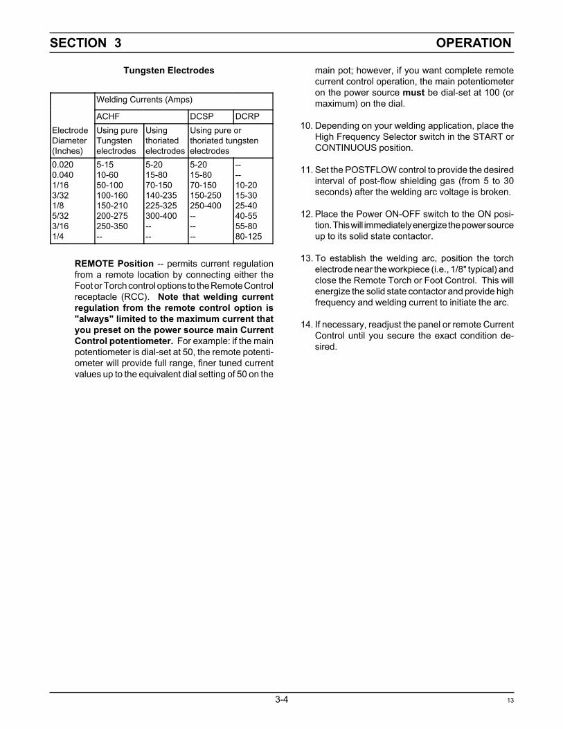
main pot; however, if you want complete remotecurrent control operation, the main potentiometeron the power source must be dial-set at 100 (ormaximum) on the dial.
10. Depending on your welding application, place theHigh Frequency Selector switch in the START orCONTINUOUS position.
11. Set the POSTFLOW control to provide the desiredinterval of post-flow shielding gas (from 5 to 30seconds) after the welding arc voltage is broken.
12. Place the Power ON-OFF switch to the ON posi-tion. This will immediately energize the power sourceup to its solid state contactor.
13. To establish the welding arc, position the torchelectrode near the workpiece (i.e., 1/8" typical) andclose the Remote Torch or Foot Control. This willenergize the solid state contactor and provide highfrequency and welding current to initiate the arc.
14. If necessary, readjust the panel or remote CurrentControl until you secure the exact condition de-sired.
Tungsten Electrodes
ElectrodeDiameter(Inches)
Welding Currents (Amps)
ACHF DCSP DCRPUsing pureTungstenelectrodes
Usingthoriatedelectrodes
Using pure orthoriated tungstenelectrodes
0.0200.0401/163/321/85/323/161/4
5-1510-6050-100100-160150-210200-275250-350--
5-2015-8070-150140-235225-325300-400----
5-2015-8070-150150-250250-400------
----10-2015-3025-4040-5555-8080-125
REMOTE Position -- permits current regulationfrom a remote location by connecting either theFoot or Torch control options to the Remote Controlreceptacle (RCC). Note that welding currentregulation from the remote control option is"always" limited to the maximum current thatyou preset on the power source main CurrentControl potentiometer. For example: if the mainpotentiometer is dial-set at 50, the remote potenti-ometer will provide full range, finer tuned currentvalues up to the equivalent dial setting of 50 on the
13

SECTION 4 MAINTENANCE
4-1
4.1 Maintenance
If this Equipment does not operate properly, stop workimmediately and investigate the cause of the malfunction.Maintenance work must be performed by an experiencedperson, and electrical work by a trained electrician. Donot permit untrained persons to inspect, clean, or repairthis Equipment. Use only recommended replacementparts.
Be sure that the wall disconnect switch or circuitbreaker is open before attempting any inspection orwork inside of the power source. Always wear safetygoggles with side shields when blowing out the unitwith low pressure air.
A. CLEANING
Since there are no moving parts (other than the fan) in thepower source, maintenance consists mainly of keepingthe interior of the cabinet clean. Periodically, remove thecover from the cabinet and blow accumulated dust anddirt from the air passages and the interior components,using clean low pressure air. It is imperative that the airpassages, to the interior of the unit, be kept free of dirtaccumulation to ensure adequate circulation of coolingair, especially over the rectifier bridge plates and PCboards. The length of time between cleaning will dependon the location of the unit and the amount of dust in theatmosphere.
B. LUBRICATION
Fan motors with old tubes require lubrication after 1 yearof service. Motors without oil tubes are permanentlylubricated and do not require any attention.
C. SPARK GAP SERVICING
This component is part of the high frequency assembly.It will probably be necessary to readjust these gaps afterextended operation, or if erratic high frequency operationis noted. It is important that the gaps be adjusted with afeeler gauge rather than by eye. Cleaning and dressing ofspark gap points is not recommended since the points aretungsten and difficult to file. Points (P/N 673578) shouldbe replaced as a set.
D. SPARK GAP ADJUSTMENT
Generally, the high frequency output of the unit increasesas the gap setting is increased. Electronic instability inother equipment may occur if the gap is opened morethan the factory-set .025 inches (+/- 002-in.). However, ifthe high frequency intensity is not sufficient for yourapplication; open or close the spark gaps until the desiredhigh frequency intensity is obtained. Remember that highfrequency radiation increases as the gap increases, andthis can cause interference in other electronic equipment.
1. Loosen retaining screw "A" only enough to freeelectrode point "C" for adjustment.
2. Place feeler gauge of proper thickness betweengap "B".
3. Apply slight pressure against loosened electrodepoint "C" so the feeler gauge is held firmly in thegap. Tighten retaining screw "A".
Figure 4-1. Spark Gap Adjustment
E. TESTING AND REPLACING BRIDGE ASSY. COM-PONENTS
SCRs and silicon diodes are devices which allow currentto flow in only one direction and block current in the otherdirection. The SCRs and silicon diodes used in this powersource are designed to provide long trouble-free opera-tion; however, should a failure occur, they may requirereplacement. The testing procedures to determine defec-tive components are as follows:
1. Silicon Diode Rectifier, D1-D2.Disconnect the power lead to the diode in order toprovide an open-circuit across the component to betested. Using an ohmmeter set to the R x 1 scale,check the resistance in the forward and reversedirection. A good diode will read high in reversedirection and low in the forward direction.
14

SECTION 4 MAINTENANCE
4-2
When replacing defective diodes, make sure mount-ing surfaces are clean. Coat mounting surfaceswith Dow-Corning No. 340 silicon heat sink com-pound, or equivalent. Replacement diode (nuts)should be tightened only until firm, and then torqued(recommended range is 275 inch-lbs min. to 325inch-lbs max.).
2. Silicon Controlled Rectifier - SCR.Disconnect the SCR wiring (but do not unclamp) tobreak continuity and provide an open circuit acrossthe component to be tested. Using an ohmmeterset to the R x 1 scale, check the resistance acrossthe SCR in both directions. A good SCR will readhigh in both directions. If the reading is low or zeroin either direction, the SCR is defective.
When replacing defective SCRs, make sure themounting surfaces are clean. Coat the mountingsurfaces with Alcoa No. 2 electrical joint com-pound, available in 8 oz. containers under P/N73585002. Make certain the polarity on the re-placement SCR is the same as on the unit beingreplaced. Place the top clamp piece over the boltsand tighten each nut hard finger tight. The clamppiece should be parallel to the top plate. Next,tighten each nut approximately 1/4 turn at a time(alternately) for two complete revolutions until theforce indicator on the clamp assembly reads 1.0kilo pounds (1000 lbs).
15


SECTION 6 REPLACEMENT PARTS
6-1
6.1 General
Replacement Parts are illustrated on the following fig-ures. When ordering replacement parts, order by partnumber and part name, as illustrated on the figure. DONOT ORDER BY PART NUMBER ALONE.
Many of the parts on the illustrations, particularly elec-tronic parts, are 'vendor item'. This means that they arestandard commercial parts made by and purchased fromother manufacturers.
Always provide the series or serial number of the unit onwhich the parts will be used. The serial number isstamped on the unit nameplate.
Replacement parts may be ordered from your distributoror from:
ESAB Welding & Cutting ProductsP.O. Box 100545Ebenezer RoadFlorence, SC 29501-0545
Be sure to indicate any special shipping instructions whenordering replacement parts.
For technical assistance directly from an ESAB servicerepresentative, call (803) 664-4416 or 5550. Additionally,ESAB offers toll free facsimile (FAX) service via 1-800-446-5693.
21


