hev test bench based on can bus sensor communication · chip, so far has more than 20 in the world...
TRANSCRIPT

Sensors & Transducers, Vol. 164, Issue 2, February 2014, pp. 163-169
163
SSSeeennnsssooorrrsss &&& TTTrrraaannnsssddduuuccceeerrrsss
© 2014 by IFSA Publishing, S. L. http://www.sensorsportal.com
HEV Test Bench Based on CAN Bus Sensor Communication
Shupeng ZHAO, Miao TIAN, Shifang ZHANG, Runze HAO,
Lei LIANG, Jiuxi LI Agriculture University of Hebei of China,
BaoDing, China E-mail: [email protected]
Received: 28 November 2013 /Accepted: 28 January 2014 /Published: 28 February 2014 Abstract: The HEV test bench based on Controller Area Network bus was studied and developed. Control system of HEV power test bench used the CAN bus technology. The application of CAN bus technology on control system development has opened up a new research direction for domestic automobile experimental platform. The HEV power control system development work was completed, including power master controller, electric throttle controller, driving simulation platform, CAN2.0 B communication protocol procedures for formulation, CAN communication monitoring system, the simulation model based on MATLAB code automatic generation technology research, etc. Maximum absorption power of the test bench is 90 kW, the test bench top speed is 6000 r/min, the CAN communication data baud rate is 10~500 k, the conventional electric measurement parameter part precision satisfies the requirement of development of HEV. On the HEV test bench the result of regenerative braking experiment shows that the result got by the test bench was closer to the results got by outdoor road test. And the fuel consumption experiment test results show that the HEV fuel consumption and the charge-discharge character are in linear relationship. The establishment of the test platform for the evaluation of the development of hybrid electric vehicle and power provides physical simulation and test platform. Copyright © 2014 IFSA Publishing, S. L. Keywords: Controller area network, Sensor communication, Hybrid electric vehicle, Test bench. 1. Introduction
In the process of hybrid electric vehicle research and development, some key technologies such as parameters matching and control strategy optimization research has been at the simulation stage, further verification need a real test environment. Hybrid power assembly test bench just provides a solution to the above key technology research [1, 2].
The establishment of the hybrid test bench, can test directly the working performance of the hybrid electric vehicle, such as dynamic performance,
economy and limited driving distance, at the same time can also test key components of a hybrid car for debugging and testing, shorten the test period of performance, reduce the risk of hybrid vehicle development and cost.
Hybrid system can carry out the vehicle controller test, including optimization of the control strategy, and the controller hardware electromagnetic compatibility in the environment of the hybrid electric vehicle, etc. Hybrid test bench can complete the vehicle performance test, the vehicle fuel economy and limited driving distance test. By bench test to study the key technology of dynamic
Article number P_1847

Sensors & Transducers, Vol. 164, Issue 2, February 2014, pp. 163-169
164
integration, such as for dynamic switching, shifting process control. Simulation technology can only provide theoretical guidance, the key problem need to debug on the test bench. On the hybrid test bench, experimental research can be carried out, such as braking energy recovery test, the battery performance test, equalization charging and discharging, and charging and discharging characteristics. Hybrid electrical assembly reliability test can also be carried out on the bench. On the hybrid test bench, we can Analog hybrid cars running status under different working conditions, find out the best economic driving pattern to provide guidance for hybrid cars driving personnel's advice [3, 4].
The Controller Area Network (CAN) is one of the widely used field bus. The CAN protocol was originally proposed by German BOSCH company in order to solve a lot of modern car interior control instrument with the data exchange between sensor, actuator. Since 1989, Intel first developed the Controller Area Network bus protocol controller chip, so far has more than 20 in the world Controller Area Network bus controller chip manufacturers, more than 110 kinds of CAN bus protocol and integration of Controller Area Network bus controller chip microprocessor chip of the controller. In North America and Western Europe, the CAN bus protocol has become the automobile computer control system and embedded industrial control bus LAN standards. Because of it excellent performance, Controller Area Network is recognized by the international organization for standardization, thus the Controller Area Network application in the field of all kinds of measurement and control is promoted.
Hybrid electric vehicle, which is different from the traditional internal combustion engine vehicle, it has the motor, batteries and other components. It need the motor controller, battery management system and energy assembly control system coordinated control together to make the equipment working in high efficient area to improve the utilization of energy, to achieve the best in the vehicle performance. As a serial bus CAN bus have the advantages of simple structure, and fault tolerance ability is strong. It has been widely applied at the scene of the car control and industrial fields. CAN bus can realize the Hybrid electric cars controller network communication. Companies such as BMW and GM, Ford, CAN bus are adopted in HEV [5].
Vehicle CAN bus technology in China starts relatively late, but along with the advance of modern automotive electronics, CAN bus will be a development trend. "863" plan about electric vehicle development plan in China also have specific provision, the new electric car development project must be to declare the vehicle based on CAN bus communication control system [6].
CAN2.0 protocol has two versions, A and B. The main difference is that ID number, the former adopts 11, the latter to 29. In this article the latter was adopted. CAN bus broke through the similar to the
RS-232 or RS-485 communication network from a host of from machine or to the limits of the machine communication format, with multiple host works, CAN hang 110 intelligent nodes at the same time. Due to its high real-time performance, CAN bus have the application scope of high-speed networks throughout to low-cost route network. CAN bus communication medium can be twisted pair, coaxial cable and optical fiber. The highest communication rate CAN reach 1 Mbps (maximum bus length 40 m). The maximum distance between any two nodes can reach 10 km (5 KBPS) for communication rate.
CAN bus technology features mainly include the follow aspects. It abolished the traditional station address code, instead of to encode communication data block, can host more host way to work. The non-destructive arbitration technology, when two nodes to transmit data on the network at the same time, take the initiative to stop the low priority node data, and the high priority nodes are not affected continue to transmit data, effectively avoid the bus conflict. The short frame structure, the effective number of bytes in each frame eight, data transmission time is short, low interference probability, to send short time. Every frame data has error detection CRC check and other measures, to ensure the high reliability of data transmission. Node in severe cases has the function of automatically shut off the bus, cutting off its connection with the bus, and the bus on the other operation is not affected.
To sum up, the development of the test bed using CAN bus has the following advantages. HEV power assembly test bench control system real-time demand is higher, with large system data flow, for each host can exchange data within the prescribed time limit, to ensure that the whole control system response characteristic. Control systems have different data communication interface controller, also has a direct output analog or digital signal sensor, using CAN bus to blend systems of each node, simplifies the wiring harness. HEV power assembly test bench is equipped with a large number of power components and high frequency electronics and the anti-interference ability of the CAN bus communication protocol, to improve the system reliability [7, 8].
2. Proposed Scheme
In recent years, with the high-speed development of domestic car, produce the problem of energy shortage and environmental pollution. In order to realize the sustainable development of auto industry, HEV become a kind of solution. It will encounter many problems in the process of research and development of HEV. Hybrid electric vehicle has internal combustion engine, motor and control system, power battery management system and main controller, etc. Before assembling prototype technology process, power system test and power distribution control scheme optimization are main task. But the conventional engine test bench is

Sensors & Transducers, Vol. 164, Issue 2, February 2014, pp. 163-169
165
difficult to meet the development of such complex process. Therefore, to establish a test technology platform is the basis of the process implementation. Task is to establish a set of high level, supporting facilities, relatively perfect experiment platform, the platform used in the study of HEV power, at the same time, it can give attention to both conventional internal combustion engine test task experiment platform [9].
Table 1. Engine starting difficulty table.
The parameter name Parameter values Maximum absorption power
90 kW
Top speed 6000 r/min Maximum torque 573 N.m CAN communication 10~500 K Baud rate
Main controller input
Dual channel analog input, 12 channel switch input, 4 channel pulse input
The main controller output 4 channel high output, 2 channel H bridge output
Main controller CAN communication
2 CAN, RS232
The gas main controller input
2 channel differential balanced position feedback
The gas main controller output
120W Dc motor
The gas main controller CAN communication
1 CAN
Speed precision ±0.2 % Torque accuracy ±0.5 % Fuel consumption accuracy
±1 %
In order to meet the demand of Hybrid test, choose a suitable dynamometer is to guarantee the development of hybrid vehicle. For the selected power dynamometer as its dynamometer device, which met the hybrid system of two-way transfer of energy requirements, at the same time, the device should also be able to routine test of small displacement engine. So dynamometer was determined for maximum absorption power of 90 kW, the top speed of 6000 r/min, the maximum torque of 573 n. M [10].
The vehicle power control system development is main technical development of the work in this topic. Development work including power research and development of main controller, electric throttle controller development, driving simulation platform for research and development, CAN2.0 B communication protocol procedures for formulation, the CAN communication monitoring system of research and development, the simulation model based on MATLAB code automatic generation technology research, etc. Due to the basic research content for the development of hybrid vehicles provides strong technical support. In order to
research the characteristics of the power component, in the process of forming joint debugging capabilities, upon the completion of the equipment installation and debugging for the first time, first of all, an independent test of K3 engine Has been studied, to obtain the K3 all performance parameters of the engine, and the data as the basic data for the design of simulation model test. And with the drive, power generation characteristics of power battery systems of the charging and discharging test, which has the ability of hybrid power test debugging ability, test bench as shown in the Fig. 1 below.
Fig. 1. HEV power test bench.
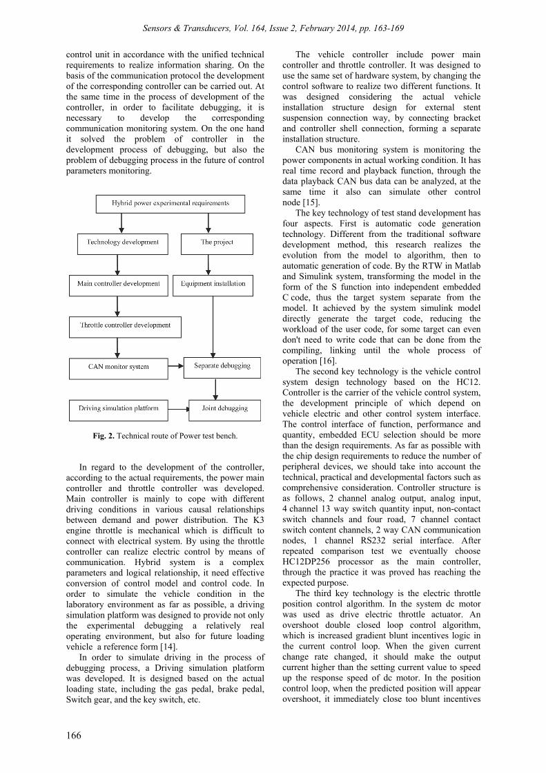
The test bench meets the needs of hybrid power development. It can also provide test for the research on hybrid assembly function. To systematically understand the working mechanism of the assembly parts, in order to optimize the vehicle energy control scheme with necessary development environment. With joint debugging as the final goal, test platform construction is decomposed into two process technology and engineering. its technical route as shown in the Fig. 2 below [11].
According to the hybrid power test requirements, technology development can be divided into technical development process and project construction process. Its purpose is to put a final goal according to the technical characteristics of different separation into different implementation of the implementation of the content. In project implementation process, according to the technical requirement of the dynamometer, it was necessary to modify existing test facilities construction, including the waterways of engine cooling system, fuel supply system and dynamometer grid system modification request to the required conditions of dynamometer [12, 13].
In the technology development process, first of all is to formulate the corresponding communication specification according to the J1939 and the characteristics of the power components. In such way the motor controller and battery management system has a technical agreement in advance, make different
Sensors & Transducers, Vol. 164, Issue 2, February 2014, pp. 163-169
166
control unit in accordance with the unified technical requirements to realize information sharing. On the basis of the communication protocol the development of the corresponding controller can be carried out. At the same time in the process of development of the controller, in order to facilitate debugging, it is necessary to develop the corresponding communication monitoring system. On the one hand it solved the problem of controller in the development process of debugging, but also the problem of debugging process in the future of control parameters monitoring.
Fig. 2. Technical route of Power test bench.
In regard to the development of the controller, according to the actual requirements, the power main controller and throttle controller was developed. Main controller is mainly to cope with different driving conditions in various causal relationships between demand and power distribution. The K3 engine throttle is mechanical which is difficult to connect with electrical system. By using the throttle controller can realize electric control by means of communication. Hybrid system is a complex parameters and logical relationship, it need effective conversion of control model and control code. In order to simulate the vehicle condition in the laboratory environment as far as possible, a driving simulation platform was designed to provide not only the experimental debugging a relatively real operating environment, but also for future loading vehicle a reference form [14].
In order to simulate driving in the process of debugging process, a Driving simulation platform was developed. It is designed based on the actual loading state, including the gas pedal, brake pedal, Switch gear, and the key switch, etc.
The vehicle controller include power main controller and throttle controller. It was designed to use the same set of hardware system, by changing the control software to realize two different functions. It was designed considering the actual vehicle installation structure design for external stent suspension connection way, by connecting bracket and controller shell connection, forming a separate installation structure.
CAN bus monitoring system is monitoring the power components in actual working condition. It has real time record and playback function, through the data playback CAN bus data can be analyzed, at the same time it also can simulate other control node [15].
The key technology of test stand development has four aspects. First is automatic code generation technology. Different from the traditional software development method, this research realizes the evolution from the model to algorithm, then to automatic generation of code. By the RTW in Matlab and Simulink system, transforming the model in the form of the S function into independent embedded C code, thus the target system separate from the model. It achieved by the system simulink model directly generate the target code, reducing the workload of the user code, for some target can even don't need to write code that can be done from the compiling, linking until the whole process of operation [16].
The second key technology is the vehicle control system design technology based on the HC12. Controller is the carrier of the vehicle control system, the development principle of which depend on vehicle electric and other control system interface. The control interface of function, performance and quantity, embedded ECU selection should be more than the design requirements. As far as possible with the chip design requirements to reduce the number of peripheral devices, we should take into account the technical, practical and developmental factors such as comprehensive consideration. Controller structure is as follows, 2 channel analog output, analog input, 4 channel 13 way switch quantity input, non-contact switch channels and four road, 7 channel contact switch content channels, 2 way CAN communication nodes, 1 channel RS232 serial interface. After repeated comparison test we eventually choose HC12DP256 processor as the main controller, through the practice it was proved has reaching the expected purpose.
The third key technology is the electric throttle position control algorithm. In the system dc motor was used as drive electric throttle actuator. An overshoot double closed loop control algorithm, which is increased gradient blunt incentives logic in the current control loop. When the given current change rate changed, it should make the output current higher than the setting current value to speed up the response speed of dc motor. In the position control loop, when the predicted position will appear overshoot, it immediately close too blunt incentives

Sensors & Transducers, Vol. 164, Issue 2, February 2014, pp. 163-169
167
logic, launch into position to maintain a given logic, thus in the three aspects of response speed, control accuracy and reducing maintain current achieved comprehensive balance.
The fourth key technology is the System diagnostic technique. According to the characteristics of the vehicle control system, fault diagnosis in three aspects, input signal, the output signal and the communication realization. The input signal used a complementary signal identification method and limit value judgment. Each channel sensor signal consists of two complementary signals output. To collect the two input signals at the same time in the controller input interface, If the signal value is not in conformity with the agreed rules in advance, that it may appear problem, and then to confirm its failure according to the scope of its limit further judgment. In this way input sensing signal to the controller such as open circuit, short circuit, which can be identified in the form of fault code on CAN bus. And the others control node also get the corresponding emergency treatment. According to the possibility of failure for output signal, at the beginning of design for the hardware chips with the basis of fault identification should be selected. Once appear to consider at the same time, the interface circuit will not make the fault by losing control to further expand, i.e. it should be able to return to original state. Because the CAN bus is a multi-master communication, so when making communication protocol it requires to establish an agreement of mutual restriction mechanism, at the same time it should have condition analysis diagnosis function. When the other node is fault, the principle is not expanding the scope of the fault. When the machine is fault, the principle is timely release fault codes and close control [17, 18]. 3. Experimental Results
As hybrid electric vehicle important function, regenerative braking system reduced fuel consumption and emission, improved energy utilization rate [19].
k b t a b aE E E F u dt F u dt , (1)
where Eb was effective energy consumption of HEV traction. Ek was effective energy consumption of HEV traction. Fb was HEV braking force. Ft was HEV driving force.
100%r
rk b
E
E E
(2)
100%rr
b
E
E (3)
Regenerative current of regenerative braking system was compared between on dynamometer and on road was shown as Fig. 4. The result of experiment shows that the result got by the test bench was closer to the results got by outdoor road test [20].
-40
-20
0
20
40
Time(s)
ess_current
Fig. 3. Current in ECE driving cycle.
-0.2
-0.15
-0.1
-0.05
0
0.05
-3 -2.5 -2 -1.5 -1 -0.5 0
△SOC(AH)
Regenerative
Current(Ah)
Dynamometer Test Rord Test
Fig. 4. Regenerative current on dynamometer in NEDC cycle.
The fuel consumption test was carried out on the hybrid test bench according to NEDC cycle. The Experimental lasted for 4000 s and 10 times repeating NEDC cycle on the test bench.
0
10
20
30
40
50
60
70
1 1054 2107 3160 4213 5266 6319 7372 8425 9478 10531 11584 12637
Time(0.1s)
SOC(
%)
Fig. 5. State of charge in NEDC.
The HEV energy consumption is the sum of electric energy and fuel consumption. The power consumption transforming into fuel consumption was calculated as follow formula: [21].
3600kfuel
fuel fuel low eng gen
EV
D Q
(4)

Sensors & Transducers, Vol. 164, Issue 2, February 2014, pp. 163-169
168
3600
3600
0.85 43000 0.35 0.85
3.02
kfuel
fuel fuel low eng gen
k
k
EV
D Q
E
E
(5)
4.14.24.34.44.54.64.74.84.95
-0.6 -0.4 -0.2 0
Q(Ah)
Fue
l c
ons
ump
tio
n(L
/10
0km
)
Fig. 6. Fuel consumption results on the test bench.
The experiment of HEV fuel consumption was carried out, and the method of hybrid vehicles fuel consumption experiment test is analyzed on the HEV test bench. The results show that the HEV fuel consumption and the charge-discharge character are in linear relationship. A fuel consumption line was obtained by the test. 4. Conclusions
In this paper, the HEV power test bench based on CAN bus was studied and developed. Control system of HEV power test bench used the CAN bus technology, which conforming to the development trend of HEV. Control system structure is simple, avoiding the overly complex control circuit. It can host work more with fast response speed. The application of CAN bus technology on control system development has opened up a new research direction for domestic automobile experimental platform. The HEV power control system development work was completed, including power master controller, electric throttle controller, driving simulation platform, CAN2.0 B communication protocol procedures for formulation, CAN communication monitoring system, the simulation model based on MATLAB code automatic generation technology research, etc. Maximum absorption power of the test bench is 90 kW, the test bench top speed is 6000 r/min, the CAN communication data baud rate is 10 ~ 500 k, the conventional electric measurement parameter part precision satisfies the requirement of development of HEV.
On the HEV test bench regenerative braking experiment was carried out. The result of experiment shows that the result got by the test bench was closer
to the results got by outdoor road test. And the method of hybrid vehicles fuel consumption experiment test is analyzed on the HEV test bench. The results show that the HEV fuel consumption and the charge-discharge character are in linear relationship. The establishment of the test platform for the evaluation of the development of hybrid electric vehicle and power provides physical simulation and test platform. References [1]. Li Yingli, Yu Yongchang, Yang Jianguo, Zhang
Zhongwei, Wang Zhiwei, Powertrain design and control parameters optimization for the hybrid electric bus, Advances in Information Sciences and Service Sciences, Vol. 4, No. 15, 2012, pp. 249-255.
[2]. Ma Zilin, Mao Xiaojian, Wang Junxi, Tang Hangbo, Zhuo Bin, Battery parameters' matching and optimizing for HEV city buses, International Journal of Digital Content Technology and its Applications, Vol. 5, No. 8, 2011, pp. 1-8.
[3]. B. Baumann, G. Washington, B. Glenn, & G. Rizzoni, Mechatronic design and control of hybrid electric vehicles, IEEE/ASME Transactions on Mechatronics, Vol. 5, Issue 1, 2000, pp. 58–72.
[4]. R. Langari, and Jong-Seob Won, Integrated drive cycle analysis for fuzzy logic based energy management in hybrid vehicles, in Proceedings of the 12th IEEE International Conference on Fuzzy Systems Fuzz’03, 25-28 May 2003, Vol. 1, pp. 290-295.
[5]. N. Schouten, M. Salman, N. Kheir, Fuzzy logic control for parallel hybrid vehicles, IEEE Transactions on Control Systems Technology, Vol. 10, Issue 3, 2002, pp. 460-468.
[6]. V. Gagliardi, A. Piccolo, A. Vaccaro, A fuzzy based control unit for the optimal power flow management in parallel hybrid electric vehicles, in Proceedings of the 19th International Electric Vehicle Symposium EVS, Seoul, Korea, 2002, pp. 560-568.
[7]. Joeri van Mierlo, and Gaston Maggetto, Innovative iteration algorithm for a vehicle simulation program, IEEE Transaction on Vehicular Technology, Vol. 53, Issue 2, 2044, pp. 401-412.
[8]. Minghui Liu, Study on vehicle control strategy and assembly parameter matching for hybrid electric bus, Changchun Jili University, Changchun, 2005
[9]. William R. Cawthorne, Fereydoon Jamzadeh, Frank Sah, The Allison transmission hybrid electric drive simulation development, Society of Automotive Engineers, SAE2000-01-3470, 2000.
[10]. Bradley Glenn, Gregory Washington, Giorgio Rizzoni, Operation and control strategies for hybrid electric automobiles, Society of Automotive Engineers, SAE2000-01-1537, 2000.
[11].Valerie H. Johnson, Keith B. Wipke, HEV control strategy for real-time optimization of fuel economy and emissions, Society of Automotive Engineers, SAE2000-01-1543, 2000.
[12]. Zhao Shu-Peng et al, The research of diagnosis expert system of EFI engine based on diagnosis tree, in Proceedings of the International Symposium on Test and Measurement (ISTM' 2003), Shenzhen, China, June 1-5, 2003, Vol. 5, pp. 4124-4126.
[13]. Heliang Zhou, Liqing Sun, Feng Wei, Hybrid electric vehicle – a kind of necessary green and economic

Sensors & Transducers, Vol. 164, Issue 2, February 2014, pp. 163-169
169
transportation tool for China, in Proceedings of the 21st International Electric Vehicle Symposium EVS, 2005, Vol. 1, pp. 729-734.
[14]. C. C. Chan, Iieliang Zhou, and Liqing Sun, Recent progress of EV in China along with the worldwide trends, in Proceedings of the 21st International Electric Vehicle Symposium EVS, 2005, Vol. 1, pp. 949-953.
[15]. Tatsuo Teratani, Kohjiro Kuramochi, Development of Toyota Mild-hybrid system (THS-M), Toyota Motor Corporation, Toyota Technical Review, Vol. 52, 2002, pp. 46-51.
[16]. Sumiko Sekiguchi, Koichi Kondo, Development of electrical 4WD system for hybrid vehicles, Toyota Motor Corporation, Toyota Technical Review, Vol. 151, 2002, pp. 86-89.
[17]. K. T. Chau, Y. S. Wong, Overview of power management in hybrid electric vehicles, Energy Conversion and Management, Vol. 43, 2002, pp. 1953-1968.
[18].Masanori Ito, Tsuoshi Hayashi, Teruo Ishishita, Development of new battery system for hybrid vehicles, Proceedings of the 21st International Electric Vehicle Symposium EVS, 2005.
[19]. Xing-Ju Wang, Tao Zhang, Xiao-Ming Xi, An assessment model of urban rail transit construction costs based on support vector machine, Journal of Convergence Information Technology, Vol. 7, No. 10, 2012, pp. 11-20.
[20]. John A. McBain, Simulation influence in the design process of mild hybrid vehicles, Society of Automotive Engineers, SAE2002-01-1196.
[21]. Yang Xu, Rong-Gang Wang, An-Yu Cheng, Rui Li, Design of online upgrade system for the software of vehicle ECU based on CAN-Bus, International Journal of Advancements in Computing Technology, Vol. 5, No. 1, 2013, pp. 79-87.
___________________
2014 Copyright ©, International Frequency Sensor Association (IFSA) Publishing, S. L. All rights reserved. (http://www.sensorsportal.com)