hey buddy, can you spare a paradigm?ewh.ieee.org/soc/cpmt/presentations/cpmt0303a.pdf ·...
TRANSCRIPT

1
Presentation to SF Bay Area CPMT Chapter Mar 2003 1
Bruce Guenin, Ph.D.Principal Research Scientist
CTO Physical Sciences Center
Sun Microsystems
Hey Buddy, Can You Spare a Paradigm?Update on Thermal Standards Work by JC15.1
March 12 , 2003
Presentation to SF Bay Area CPMT Chapter Mar 2003 2
Acknowledgments
Bernie SiegalTom TarterThe many members of JC15.1 who have contributed to 13 years of thermal standards leadershipMembers of the European consortia: DELPHI, SEED, and PROFIT, for their participation on JC15.1 to transplant the use of 21st century simulation methods

2
Presentation to SF Bay Area CPMT Chapter Mar 2003 3
Outline
The World We Live InOld and New ParadigmsThe Need for Industry StandardsThe JEDEC JC15.1 CommitteeJEDEC Thermal Test MetricsJC15.1 Thermal Modeling Standards Work
Presentation to SF Bay Area CPMT Chapter Mar 2003 4
The Market
The good old days:– If you build it they will come.– Technology alone would sell– Obsolescence was a friend we could count on
The bad new days:– The customer’s eyes glaze over when they hear about
another wiz-bang techno gadget.– The customer is looking for real utility and ease of use
along with commodity pricing. The technical complexity must be hidden from the user
3
Presentation to SF Bay Area CPMT Chapter Mar 2003 5
Definition
par·a·digm :3. A set of assumptions, concepts, values, and practices that constitutes a way of viewing reality for the community that shares them, especially in an intellectual discipline.
Presentation to SF Bay Area CPMT Chapter Mar 2003 6
Definition (cont)
USAGE NOTE:……..Applications of the term in other contexts show that it can sometimes be used more loosely to mean “the prevailing view of things.” The Usage Panel splits down the middle on these nonscientific uses of paradigm. Fifty-two percent disapprove of the sentence The paradigm governing international competition and competitiveness has shifted dramatically in the last three decades

4
Presentation to SF Bay Area CPMT Chapter Mar 2003 7
The Electronics Food Chain
Chip DesignChip
FabSubstrate Design
Substrate Fab
Package Assembly
Encapsulant
Die Attach System Integrator
Presentation to SF Bay Area CPMT Chapter Mar 2003 8
Old Paradigm
• Suppliers ship products• Customer companies
have their own internal engineering flows
• Data from suppliers of limited value in supporting engineering
What’s wrong with continuing the old paradigm: Answer: the process involves duplication of effort, takes too long, and costs too much money
ChipDesignChip
FabSubstrateDesign
SubstrateFab
PackageAssembly
Encapsulant
DieAttach System Integrator

5
Presentation to SF Bay Area CPMT Chapter Mar 2003 9Package Assembly
New Paradigm: Flow of complete data sets for insertion into engineering processes emphasizing simulation.
Chip Design
Substrate Design
Die Attach
Thermal, mechanical, rheological data
System Integrator
Encapsulant
Thermal, mechanical, mold flow data
Compact Thermal Model, Electrical SPICE
Deck, etc.
Presentation to SF Bay Area CPMT Chapter Mar 2003 10
Old Paradigm/New ParadigmOld Paradigm
– You order it– We ship it– We’ll characterize it, but you really better redo it for yourself
New Paradigm– You order it– We ship it– We’ll characterize it and provide you with a data set to support all
engineering functions involving our product– e.g.: complicated network of suppliers and customers acts like a
virtual company
6
Presentation to SF Bay Area CPMT Chapter Mar 2003 11
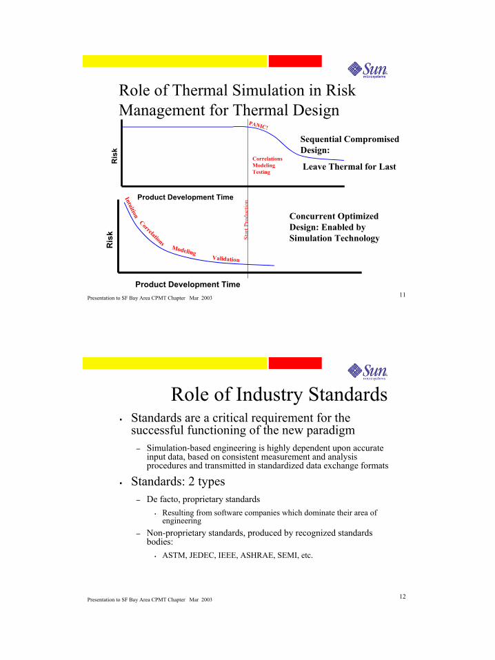
Role of Thermal Simulation in Risk Management for Thermal Design
Star
t Pro
duct
ion
Ris
k
Product Development Time
Intuition
CorrelationsModeling
Validation
Ris
k
Product Development Time
PANIC!
CorrelationsModelingTesting
Sequential Compromised Design:
Leave Thermal for Last
Concurrent Optimized Design: Enabled by Simulation Technology
Presentation to SF Bay Area CPMT Chapter Mar 2003 12
Role of Industry StandardsStandards are a critical requirement for the successful functioning of the new paradigm
– Simulation-based engineering is highly dependent upon accurate input data, based on consistent measurement and analysis procedures and transmitted in standardized data exchange formats
Standards: 2 types– De facto, proprietary standards
Resulting from software companies which dominate their area of engineering
– Non-proprietary standards, produced by recognized standards bodies:
ASTM, JEDEC, IEEE, ASHRAE, SEMI, etc.

7
Presentation to SF Bay Area CPMT Chapter Mar 2003 13
Value of Open StandardsDriven by Suppliers and Customers
– Interests of both parties are served
Give no unfair advantage to any competitor– Promote entry of new competitors into market
Provide full documentation of test and simulation methods
– Serve to raise level of technology as actually practiced in an industry
Provide mechanism for cooperation between competitors without compromising IP or engaging in unlawful collusion
– A rising tide lifts all boats
Presentation to SF Bay Area CPMT Chapter Mar 2003 14
Evolution of Packaging
• The Future• System in
Package
• Stacked Chip Technology
• Opto-electronic Packaging
• Or ???
Adapted from Japan Jisso Technology Roadmap -- 2001 Edition

8
Presentation to SF Bay Area CPMT Chapter Mar 2003 15
History of Thermal Standards
Semi Stds.
JEDEC Th. Test. Stds.
DELPHI, SEED, PROFIT,…. CTM Methodology
Mil Stds.
JEDEC Simulation Stds.
Stan
dard
s A
ctiv
ities
Pack
agin
g Te
chno
logy Thru hole SMT
(Peripheral)SMT
(Area Array)
1 W 3 W 40 W
Presentation to SF Bay Area CPMT Chapter Mar 2003 16
JEDEC 15.1 SubcommitteeFounded in 1990Over 40 member companiesSemiconductor, packaging, and software companiesCharter of committee:
– To generate thermal measurement and modeling standards for microelectronic packaging
– These standards shall be meaningful, consistent, and shall be proven to be scientifically sound
– The standards will provide a common means of comparison of thermal phenomena for users of microelectronic packaging
Proposed standards are validated using testing and computer simulation, by individuals and in round-robin exercises

9
Presentation to SF Bay Area CPMT Chapter Mar 2003 17
Articles and Presentations Resulting from JC15.1 ActivitesB. Joiner, B. Siegal, T. Tarter, and B. Bright, “Use of Experimental Data in Guiding Thermal Specification Development,” Proceedings, SEMI-THERM XII Conference, March 1996, pp. 65-71.
D. Edwards, “Development of JEDEC Standard Thermal Measurement Test Boards,” Proceedings, SEMI-THERM XII Conference, March 1996, pp.183-190.
B. Joiner and V. Adams, “Measurement and Simulation of Junction to Board Thermal Resistance and Its Application in Thermal Modeling,” Proceedings, SEMI-THERM X_Conference
B. Joiner, “The Use of Junction-to-Board Thermal Resistance in Predictive Engineering,” Electronics Cooling, Vol5, No. 1, January, 1999, pp. 14-17.
A. Claassen, B. Joiner, Z. Celik, and A. Ortega, “Development of the JEDEC Forced Convection Standard,” Proceedings, SEMI-THERM XVI Conference, March 2000, pp. 116-127.
B. Guenin, “Component Thermal Characterization,” Electronics Cooling, Vol 7, No. 1, February, 2001, pp. 36 -44.
B. Guenin, “Thermal Standards for the 21st Century,” Proceedings, SEMI-THERM XVIII Conference, March 2002
B. Guenin, “The JEDEC JC15.1 Thermal Standards Subcommittee: An Agent for Promoting a Paradigm Shift in Thermal Simulation,” Presentation to San Jose IEEE, CPMT Chapter, March, 2002.
B. Siegal and B. Guenin, “Challenges in the Development of a ΘJC Thermal Test Standard,” IMAPS Advanced Technology Workshop on Thermal Management for High Performance Computing and Telcom/Wireless Applications, Palo Alto, October 24, 2002.
Presentation to SF Bay Area CPMT Chapter Mar 2003 18All standards are available for downloading free of charge from www.jedec.org
Electrical TestMethod
JESD 51_1
Infrared TestMethod
Test MethodImplementationfor Active Die
Transient TestMethod
THERMALMEASUREMENT
NaturalConvectionJESD 51_2
ForcedConvectionJESD51-6
Heat SinkJunction-To-
Case
PCBJunction-To-
Board
THERMALENVIRONMENT
Low EffectiveThermal Cond.
Thermal Test Bd.JESD51_3
Hi EffectiveThermal Cond.
Thermal Test Bd.JESD51-7
Area ArrayThermal Test Bd.
Direct AttachThermal Test Bd.
JESD 51-5
Through HoleThermal Test Bd.
Array and DIL
Chip Size Package
Direct Chip AttachThermal Test Bd.
COMPONENTMOUNTING
Thermal Test ChipGuideline
(Wire Bond)JESD51_4
Thermal Test ChipGuideline
Flip-Chip / DCA
DEVICECONSTRUCTION
Detailed Model
Guideline
Submerged DualJet Impingement
Conduction ModelValidation Method
Dual Cold PlateConduction ModelValidation Method
Compact ModelGuideline
THERMALMODELING
Application ofThermal
Standards Guideline
SpecificationGuidelines for
PackageManufacturers
SpecificationGuidelines forPCB Tolerance
Verification
MEASUREMENTAPPLICATION
OVERVIEWJESD 51
Standard Published
Standard Proposed(in committee work group)
Standard Suggested
ThermocoupleMeasurement
Guideline
InterfaceMeasurement
Method
JESD51-8
JESD51-9
JESD 51-10 & 11
Published, Proposed, and Suggested Standards JESD51-xx Series

10
Presentation to SF Bay Area CPMT Chapter Mar 2003 19
Modular Format For Test Standards
• User picks various components of the test appropriate for his application– Measurement Technique
• e.g.: electrical– Test Environment
• e.g.: natural convection– Component Mounting
• E.g.: low conductivity test board for surface-mount, leaded package, and
– Device Construction• e.g.: wirebond thermal test chip
• Standard specifies test metrics and method of calculation– ΘJA, ΨJB, ΨJT, etc.
TJTTTB
TA
Presentation to SF Bay Area CPMT Chapter Mar 2003 20
Any (single-chip package) thermal metric is calculated by measuring the junction temperature and a reference temperature in a specified environment and dividing by the total power
ΘJX
– Thermal Resistance
– Measures ease of heat flow between junction and region whose reference temperature is TX
– Nearly all of heat flows to region represented by TX
ΨJX
– Thermal Characterization Parameter
– Correlation between TJ and another temperature TX
– Only part of heat flows to region represented by TX
JEDEC Thermal Metrics
PTT XJ
JX−
=Θ
PTT XJ
JX−
=Ψ

11
Presentation to SF Bay Area CPMT Chapter Mar 2003 21
Test package on standard board
– 2 board designs per package type
Low Conductivity (1S) Board; 2oz Cu tracesHi Conductivity (2S2P) Board; 1 oz Cu planes
– Convective heat transfer environment
Natural Convection ChamberWind Tunnel
– Measure temperatures
TJUNCTION, TAIR, TBOARD, TTOP
– Calculate thermal metrics versus power, air speed
ΘJA
– Figure of merit related to performance of package and board in convective environmentΨJB
– Correlation between TJ and TB; can be used to predict TJ is TB is knownΨJT
– Correlation between TJ and TT; can be used to predict TJ is TT is known
Basis of JEDEC Testing Convective Environment
TJTTTB
Presentation to SF Bay Area CPMT Chapter Mar 2003 22
Thermal Measurement in Convective Heat Flow Environment
Forced Convection Θ JMA Test Results35.0 mm, 388 Ld, with 1.27 mm Pitch @ 3.0 Watts
101214161820222426
0 0.5 1 1.5 2 2.5Air Velocity (m/s)
ΘJM
A(°
C/W
)
2S2P/1S0P
2S2P/1S2P
Laminate/BoardBuild-Up
JEDEC Compliant Test Boards
ΘJA is meaningful only for packages tested in the standard environment. Even in the std. env. it is influenced by the board, and air velocity. It cannot be used to predict the junction temperature in the application
●ΘJA
–Strong function of air velocity●ΨJB
–Weak function of air velocity–Good predictor of package performance when no heatsink is attached to package top–Is nearly equal to ΘJB at low air velocities●ΨJT
–Is usually a small number, on the order of 1 C/W–Convenient means of determining junction temperature in operating system

12
Presentation to SF Bay Area CPMT Chapter Mar 2003 23
Test package on standard board
– 2 board designs per package type
Low Conductivity (1S) Board; 2oz Cu tracesHi Conductivity (2S2P) Board; 1 oz Cu planes
– Conductive heat transfer environment
“Hard” (conductive) boundary conditions
ΘJB
– Heat extracted from periphery of board– Forces nearly 100% of heat to flow through board– Invariant metric (ΨJB depends upon air velocity)– Used to predict junction temperature when dominant heat flow is through board
ΘJC
– Heat extracted from top of package– Forces nearly 100% of heat to flow through top of package– Used to predict junction temperature when heat sink is attached to top of package
Basis of JEDEC Testing Conductive Environment
TC
TB
TJ
Presentation to SF Bay Area CPMT Chapter Mar 2003 24
Relationship between Θ values and Ψvalues
% of Heat Flow out Pkg Top0 % 100 %
Pack
age
Met
ric (C
/W)
ΨJB
ΨJT
ΘJB
ΘJC
% of Heat Flow out Pkg Top0 % 100 %
Pack
age
Met
ric (C
/W)
ΨJB
ΨJB
ΨJTΨJT
ΘJB
ΘJC
TJ
ΘJB
TB
TT
ΘJC
P
PTOP
P - PTOP
∆ΤJT = PTOP * ΘJC
∆ΤJB = (P – PTOP) * ΘJB
TJ
ΘJB
TB
TT
ΘJC
P
PTOP
P - PTOP
∆ΤJT = PTOP * ΘJC
∆ΤJB = (P – PTOP) * ΘJB
Typical Range for Pkgsw/o Heatsinks
Larger ∆TJT = Larger ΨJT , etc.

13
Presentation to SF Bay Area CPMT Chapter Mar 2003 25
JEDEC Test MetricsProvide basis of comparison of thermal performance of competing package designs.Provide means of estimating junction temperature in applications with the judicious application of engineering judgementCan be used to represent package thermal performance in system-level simulations, however, they are not the optimum means of doing so
Presentation to SF Bay Area CPMT Chapter Mar 2003 26
ΘJC Test Proposal #1 Conventional Cold Plate
Case Temp MeasurementHigh Cond. Pkgs.
Low Cond. Pkgs.Heat Loss Measurement

14
Presentation to SF Bay Area CPMT Chapter Mar 2003 27
ΘJC Test Proposal #2 Heat Flux Column
Committee decision: combine best features of each: case temp measurement of method #1 with case power measurement of method #2
Presentation to SF Bay Area CPMT Chapter Mar 2003 28
Framework for Modeling Standards Under Development
DetailedMod el
Gu ideline
CompactThermalMod el
Overview
Mod eling Process
DELPHICTM
Guideline
2-ResistorCTM
Standard?
DetailedMod el
Validation
CompactMod el
Validation
ValidationReport
Mod elError
Analys is
Validation Process& Repo rting
Doub leColdPlate
JEDECMetrics
Mod ifiedRing Cold
Plate
ValidationMethod
ComponentModeling
Terms andDefinitions
FileInterchange
Format
General
= Activity Area

15
Presentation to SF Bay Area CPMT Chapter Mar 2003 29
Intent of Thermal Modeling Standards and Guidelines
Thermal simulation technology is progressing at a rapid paceThe committee is striving to provide a framework for the application of current methods, while fostering innovation in simulation methodsTry to find a balance between procedures that must be standardized and those which are up to user discretionAt minimum, thermal standards and guidelines seek to provide a common set of definitions, indicate what aspects of the modeling procedure should be documented, and provide standard methods for model validation.
Presentation to SF Bay Area CPMT Chapter Mar 2003 30
Example of Detailed Package/Test Board Solid Model
Drop-In Copper Heat Spreader 1/8 th View
Dielectrics Hidden

16
Presentation to SF Bay Area CPMT Chapter Mar 2003 31
Finite Element Analysis Thermal Solutions
1/8 th ViewTop View
Presentation to SF Bay Area CPMT Chapter Mar 2003 32
Detailed Model Solutions
Provide a complete 3-D mapping of temperatures throughout package and boardCannot be used to transmit thermal package performance between supplier and customer– Data set is not portable
Model is too large (1000’s of nodes)Software-tool specific

17
Presentation to SF Bay Area CPMT Chapter Mar 2003 33
Role of Modeling in Traditional JEDEC Methodology
Testing and modeling produce similar outputs: standard thermal metricsModeling is validated against results of standard testTesting and validated models are interchangeable as generators of thermal metrics
DetailedThermal Model
JEDEC-StdThermal Test
Validation OUTPUTS
ΘJX, ΨJX
ΘJX, ΨJX
(a) DetailedThermal Model
JEDEC-StdThermal Test
Validation OUTPUTS
ΘJX, ΨJX
ΘJX, ΨJX
DetailedThermal Model
JEDEC-StdThermal Test
Validation OUTPUTS
ΘJX, ΨJX
ΘJX, ΨJX
(a)
Presentation to SF Bay Area CPMT Chapter Mar 2003 34
2-Resistor Compact Model
Leverages established methodsUses existing JEDEC test standards to generate the resistor values
– ΘJC and ΘJB
Lower accuracy than more sophisticated methods (e.g. DELPHI)No means of estimation of error from the method of generationIntent is to establish a precedent in the industry for suppliersfurnishing compact thermal models
– Encourage a migration to use of more accurate methods

18
Presentation to SF Bay Area CPMT Chapter Mar 2003 35
DELPHI Compact Thermal Model
A DELPHI CTM represents the package as a network of resistorsThis network accurately predicts TJindependent of the boundary conditionsThe network links the junction to all major surfaces of heat extraction
– Typically 8-10 resistors– Significant reduction in number of nodes compared with
detailed model– Accuracy typically within 95% or better
Presentation to SF Bay Area CPMT Chapter Mar 2003 36
Comparision of Detailed Model and Compact Model
PQFP Package

19
Presentation to SF Bay Area CPMT Chapter Mar 2003 37
DELPHI CTM MethodologyTesting is used to validate Detailed Thermal Model in a small number of conditions
Detailed model is used to generate outputs in under large number of boundary conditions
Values of “Links” in Thermal Compact Model are generated by optimization procedure to minimize error between CM and Detailed Model under same set of boundary conditions
Testing has a subordinate role in validation procedure
Detailed Thermal Model
Thermal Test: “Hard”
Boundary Conditions
Validation
OUTPUTSet of TJ’s and nodal fluxes
calculated at a large number of
different boundary conditions
Compact Thermal Model
Optimization Procedure
System-level Model
Import
OUTPUTS:
TJ , TA , etc.
Detailed Thermal Model
Thermal Test: “Hard”
Boundary Conditions
Validation
OUTPUTSet of TJ’s and nodal fluxes
calculated at a large number of
different boundary conditions
Compact Thermal Model
Optimization Procedure
Detailed Thermal Model
Thermal Test: “Hard”
Boundary Conditions
Validation
OUTPUTSet of TJ’s and nodal fluxes
calculated at a large number of
different boundary conditions
Compact Thermal Model
Optimization Procedure
Detailed Thermal Model
Thermal Test: “Hard”
Boundary Conditions
Validation
OUTPUTSet of TJ’s and nodal fluxes
calculated at a large number of
different boundary conditions
Compact Thermal Model
Optimization Procedure
System-level Model
Import
OUTPUTS:
TJ , TA , etc.
Presentation to SF Bay Area CPMT Chapter Mar 2003 38
Typical DELPHI Boundary Condition Set

20
Presentation to SF Bay Area CPMT Chapter Mar 2003 39
Double Cold Plate Test Method
Provides 4 sets of “hard” boundary conditions
Presentation to SF Bay Area CPMT Chapter Mar 2003 40
Standard Methods of Comparision of CTMs
Analytical or test based?Do calculated results retain any artifact of test environment?Provide calculation of BCI Index for a standard test set of boundary conditions– Provides a Figure of Merit for ranking
competing CTM methodologies

21
Presentation to SF Bay Area CPMT Chapter Mar 2003 41
ConclusionsBuddy, you can keep your paradigm, we’ve already got oursJC15.1 is completing a 10+ year effort to put into place a robust series of thermal test standardsJC15.1 Committee is working on plan to establish a comprehensive framework to support
– The use and continued development of detailed and compact models
– Industry requirements for efficient data handoff between component suppliers and customers
Presentation to SF Bay Area CPMT Chapter Mar 2003 42
Update on JC15.1 Thermal Standards Work