hägglunds due drive unit - bosch rexroth
TRANSCRIPT
RE 15325/04.2020, Bosch Rexroth AB
Content
1 Ordering 42 Function Hägglunds DUe 63 Circuit diagram 104 Technical data 135 Accessories 596 Packing 607 Required and additional documents 61
Features ▶ Closed sound insulated cabinet ▶ Vertical assembly - small footprint ▶ Configurable for many applications and customer
demands ▶ Equipped with Hägglunds advanced control system
Hägglunds DUeDrive Unit
Valid for: ▶ Flow capacity: Up to 3000 lpm at 50Hz ▶ Flow capacity: Up to 3600 lpm at 60Hz ▶ Max operating pressure: 350 bar (5076 psi) ▶ Frame size: Small, Medium and Large ▶ 2-3 hydraulic compartment assembly ▶ Pump size: 40-750 cc ▶ 1-4 pump assembly
RE 15325/04.2020Replaces: 03.2018

2/62 Drive unit | Hägglunds DUe
Bosch Rexroth AB, RE 15325/04.2020

Contents
1 Ordering ............................................................... 41.1 Ordering code ...................................................... 4
2 Function Hägglunds DUe ..................................... 62.1 General ................................................................ 62.1.1 Test certificate ..................................................... 72.1.2 Standards ............................................................. 72.1.3 Ambient temperature ........................................... 72.1.4 Combination of pump and electric motor ............. 8
3 Circuit diagram .................................................. 103.1 Simplified hydraulic circuit single SP pump ....... 103.2 Simplified hydraulic circuit SP double pumps .... 113.3 Monitoring logic diagram .................................... 12
4 Technical data .................................................... 134.1 Drive unit (DUe) ................................................. 134.1.1 Weights ............................................................. 134.1.2 Positioning the DUe ........................................... 154.1.3 Dimensions DUe ................................................. 164.1.4 Dimensions DUe with air-oil cooler .................... 184.1.5 Dimensions DUe with water-oil plate cooler ....... 194.1.6 Dimensions DUe with water-oil tube cooler ........ 204.1.7 Connections ....................................................... 214.1.8 DUe oil pan volume ............................................ 214.2 Main components ............................................... 224.2.1 Electric motor .................................................... 224.2.2 Main pump SP .................................................... 244.2.3 Water-oil cooler - plate type ............................... 304.2.4 Water-oil cooler - tube type ................................ 324.2.5 Hägglunds HDC cooler (air-oil cooler) ................ 334.2.6 Tank ................................................................... 374.2.7 Oil filter .............................................................. 384.2.8 Hägglunds Spider .............................................. 394.2.9 Hägglunds ICp Pump control ............................ 404.3 Other components ............................................. 414.3.1 Water valve ........................................................ 414.3.2 Suction line valve ............................................... 434.3.3 Clogging Indicator, oil filter ................................ 444.3.4 Air breather ........................................................ 454.3.5 Tank bladder ...................................................... 454.3.6 Electronic level and temperature sensor ............ 464.3.7 Accumulator ....................................................... 474.3.8 Auxillary pumps ................................................. 484.3.9 Pressure sensor ................................................. 494.3.10 Oil heater ........................................................... 504.3.11 Drain temperature sensor ................................... 514.3.12 Electrical connection box ................................... 51
4.3.13 LED lightning ...................................................... 514.4 Sound ................................................................ 524.5 Environment options .......................................... 554.5.1 Flushing ............................................................. 554.5.2 Brake release system .......................................... 554.5.3 Low temperature ................................................ 554.5.4 High temperature ............................................... 554.5.5 Sound protection ............................................... 564.5.6 Dust protection .................................................. 564.5.7 Rain protection................................................... 564.5.8 Anchoring possibility .......................................... 564.5.9 Machine feet ...................................................... 574.5.10 Oil pan ............................................................... 574.5.11 Painting .............................................................. 574.5.12 Hazardous areas ................................................. 574.6 External pipe work General ................................ 584.6.1 Pipe size ............................................................. 584.6.2 Material in hydraulic pipes ................................ 584.6.3 Pipe couplings ................................................... 584.6.4 Pipe clamps ....................................................... 584.6.5 Welded couplings .............................................. 584.6.6 Hoses ................................................................ 584.7 Hydraulic fluids .................................................. 58
5 Accessories ........................................................ 595.1 Spidercom .......................................................... 595.2 VpCI ................................................................... 59
6 Packing ............................................................... 606.1 Packing procedure.............................................. 606.2 Items not assembled at delivery ......................... 606.2.1 Items not assembled at delivery ......................... 606.2.2 Small items not assembled at delivery ............... 60
7 Required and additional documents ................. 61
Hägglunds DUe | Drive unit 3/62
RE 15325/04.2020, Bosch Rexroth AB

01 Drive unit
DU
02 Type
Excellence E
03 Frame size
Small frame S
Medium frame M
Large frame L
04 Number of compartments
One compartment 1
Two compartments 2
Three compartments 3
Electric motor size
05 Electric power (kW) - Right compartment 011
06 Electric power (kW) - Left compartment 015
022
030
037
045
055
075
090
110
132
160
200
250
315
355
400
500
Pump size SP pumps - upper
0709
Pump size (cc) SP pumps - upper right compartment 040
Pump size (cc) SP pumps - upper left compartment 071
125
180
250
355
500
750
1 Ordering
01 02 03 04 05 06 07 08 09 10 11 12 13 14 15 16
DU E - L 2 - 315 / 000 - 500 + 000 / 000 + 000 - 0 - W - Y - S - 0400 / 50
1.1 Ordering codeIn order to identify Hägglunds equipment, the following ordering code is used.
Example Hägglunds DUE-L2:
4/62 Drive unit | Hägglunds DUe
Bosch Rexroth AB, RE 15325/04.2020

Pump size SP pumps - lower
08 Pump size (cc) SP pumps - lower right compartment 040
10 Pump size (cc) SP pumps - lower left compartment 071
125
180
250
355
500
11 Hazardous area
Not used in hazardous area 0
ATEX 1
Other 9
12 Cooler type
Air oil cooler A
Water oil cooler W
13 Electric motor
Included in Drive Unit Y
Customer supplied N
14 Control system
Hägglunds Spider control system S
No control system - Only terminal box N
Hägglunds ICp pump control D
15 Voltage (V)
Main Voltage
16 Frequency (Hz)
50
60
Hägglunds DUe | Drive unit 5/62
RE 15325/04.2020, Bosch Rexroth AB
2 Function Hägglunds DUe
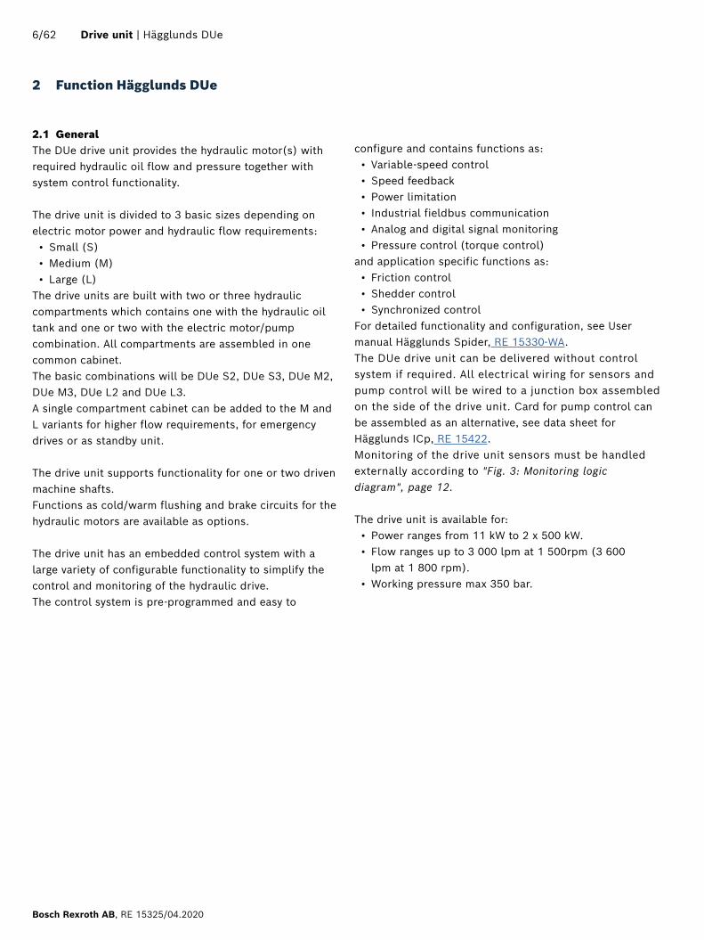
2.1 GeneralThe DUe drive unit provides the hydraulic motor(s) with required hydraulic oil flow and pressure together with system control functionality.
The drive unit is divided to 3 basic sizes depending on electric motor power and hydraulic flow requirements:• Small (S)• Medium (M)• Large (L)
The drive units are built with two or three hydraulic compartments which contains one with the hydraulic oil tank and one or two with the electric motor/pump combination. All compartments are assembled in one common cabinet.The basic combinations will be DUe S2, DUe S3, DUe M2, DUe M3, DUe L2 and DUe L3.A single compartment cabinet can be added to the M and L variants for higher flow requirements, for emergency drives or as standby unit.
The drive unit supports functionality for one or two driven machine shafts. Functions as cold/warm flushing and brake circuits for the hydraulic motors are available as options. The drive unit has an embedded control system with a large variety of configurable functionality to simplify the control and monitoring of the hydraulic drive. The control system is pre-programmed and easy to
configure and contains functions as: • Variable-speed control• Speed feedback• Power limitation• Industrial fieldbus communication• Analog and digital signal monitoring• Pressure control (torque control)
and application specific functions as:• Friction control• Shedder control• Synchronized control
For detailed functionality and configuration, see User manual Hägglunds Spider, RE 15330-WA. The DUe drive unit can be delivered without control system if required. All electrical wiring for sensors and pump control will be wired to a junction box assembled on the side of the drive unit. Card for pump control can be assembled as an alternative, see data sheet for Hägglunds ICp, RE 15422.Monitoring of the drive unit sensors must be handled externally according to "Fig. 3: Monitoring logic diagram", page 12.
The drive unit is available for:• Power ranges from 11 kW to 2 x 500 kW.• Flow ranges up to 3 000 lpm at 1 500rpm (3 600
lpm at 1 800 rpm).• Working pressure max 350 bar.
6/62 Drive unit | Hägglunds DUe
Bosch Rexroth AB, RE 15325/04.2020

2.1.1 Test certificateTest certificates for each drive unit may be provided upon request. They are issued according to European Standard EN 10204 - 3.1.
2.1.2 StandardsDeclaration of Incorporation, as defined by the EC Machinery Directive 2006/42/EC, Appendix IIB
Control system• EMC Directive 2014/30/EU• Low Voltage Directive 2014/35/EU
Quality assurance system, certified to standard ISO 9001.
2.1.3 Ambient temperatureUpper limitA standard drive unit has an upper ambient temperature limit of 40°C (104°F).
Lower limitA standard drive unit has a lower ambient temperature limit of -20°C (-4°F). Below 0°C (32°F) should water oil cooler be used due to freezing point of water.
Hägglunds DUe | Drive unit 7/62
RE 15325/04.2020, Bosch Rexroth AB
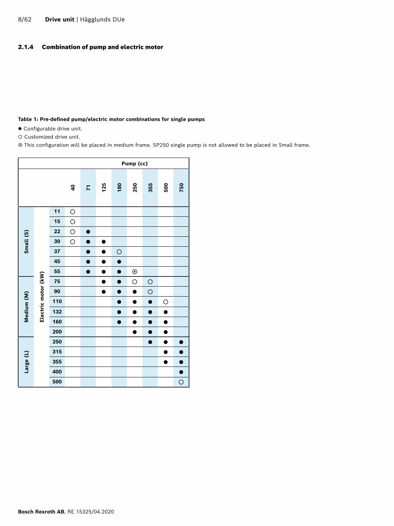
2.1.4 Combination of pump and electric motor
Table 1: Pre-defined pump/electric motor combinations for single pumps
Configurable drive unit. Customized drive unit. This configuration will be placed in medium frame. SP250 single pump is not allowed to be placed in Small frame.
Pump (cc)
40 71 125
180
250
355
500
750
Sm
all
(S)
Elec
tric
mot
or (
kW)
11 15 22 30 37 45 55
Med
ium
(M
)
75 90 110 132 160 200
Larg
e (L
)
250 315 355 400 500
8/62 Drive unit | Hägglunds DUe
Bosch Rexroth AB, RE 15325/04.2020

Table 2: Pre-defined pump/electric motor combinations for tandem pumps
Configurable drive unit. Customized drive unit.
Pump (cc)
40 40 71 40 71 125
40 71 125
180
40 71 125
180
250
40 71 125
180
250
355
40 71 125
180
250
355
500
40 71 71 125
125
125
180
180
180
180
250
250
250
250
250
355
355
355
355
355
355
500
500
500
500
500
500
500
Med
ium
(M
)
Elec
tric
mot
or (
kW)
11
15
22 30 37 45 55 75
90 110 132 160 200
Larg
e (L
)
250 315 355 400 500
Hägglunds DUe | Drive unit 9/62
RE 15325/04.2020, Bosch Rexroth AB

3 Circuit diagram
3.1 Simplified hydraulic circuit single SP pumpFeatures; air-oil cooler, cold flushing via check valve, cold flushing pump case
DD00109194
Fig. 1: Simplified hydraulic circuit single pump
10/62 Drive unit | Hägglunds DUe
Bosch Rexroth AB, RE 15325/04.2020
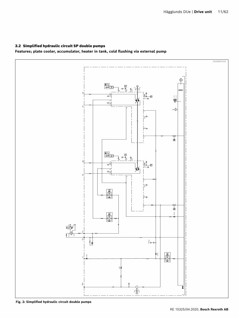
3.2 Simplified hydraulic circuit SP double pumpsFeatures; plate cooler, accumulator, heater in tank, cold flushing via external pump
DD00097420
Fig. 2: Simplified hydraulic circuit double pumps
Hägglunds DUe | Drive unit 11/62
RE 15325/04.2020, Bosch Rexroth AB

3.3 Monitoring logic diagram
Fig. 3: Monitoring logic diagram
DD00066427
12/62 Drive unit | Hägglunds DUe
Bosch Rexroth AB, RE 15325/04.2020

4 Technical data
4.1 Drive unit (DUe)
4.1.1 Weights
Cabinet size Weight without oil, electric motor, tank, top cover, pump and cooler
kg* lb*
DUe S2 750 1 650
DUe S3 1 100 2 450
DUe M2 1 100 2 450
DUe M3 1 750 3 900
DUe L2 1 400 3 100
DUe L3 2 300 5 100* Values are rounded to the higher number fifty.
Table 3: Weight drive unit
SiemensWeight
(kW) kg lb
11 83 183
15 100 220
22 170 375
30 240 529
37 285 628
45 320 705
55 420 926
75 570 1 257
90 670 1 477
110 760 1 676
132 960 2 116
160 990 2 183
200 1 190 2 623
250 1 326 2 923
315 1 653 3 644
355 2 026 4 467
400 2 116 4 665
500 2 296 5 062
Tank size Weight
l kg lb
120 130 287
255 160 353
350 180 397
505 230 507
765 245 540
835 285 628
Top cover height
Frame size
2 compartments 3 compartments
mm kg lb kg lb
320 S 105 232 155 342
320 M 120 265 190 419
500 M 136 300 215 474
620 L 155 342 250 551
700 M 155 342 240 529
800 L 170 375 290 639
900 M 185 408 265 584
1 000 L 190 419 320 705
1 100 M 210 463 290 639
1 200 L 250 551 365 805
1 300 M 215 474 315 694
1 400 L 270 595 395 871
1 700 L 305 672 440 970
2 000 L 340 750 485 1 069
Table 4: Weight top cover
Electric motor
Pump size
Weight
kW cc kg lb
Cold flushing 3 32 90 198
Warm and cold flushing
7.5 32 / 56 152 335
Brake circuit 15 bar 9 20
60 / 200 bar 3 4/ 11 67 148
Table 5: Weight tank
Table 6: Weight electric motor
Table 7: Weight replenishment (included electric motor, pump, and valve block)
Hägglunds DUe | Drive unit 13/62
RE 15325/04.2020, Bosch Rexroth AB

Table 8: Weight pump
Pump Weight Attachment kit Weight
kg lb kg lb
SP40 74 163 SP40 + SP40 4 9
SP71 98 216 SP71 + SP71 5 11
SP125 150 331 SP125 + SP125 10 22
SP180 158 348 SP180 + SP180 10 22
SP250 267 589 SP250 + SP250 25 55
SP355 277 611 SP355 + SP355 29 64
SP500 394 869 SP500 + SP500 33 73
SP750 540 1 191
Table 9: Weight air cooler
Air cooler type Weight
kg Ib
HDC 050-4 38 84
HDC 060-4 60 132
HDC 080-4 101 223
HDC 085-6 131 289
HDC 090-6 173 381
HDC 100-4 222 489
HDC 100-6 196 432
HDC 200-4 429 946
HDC 200-6 357 787
Example
Given:Cabinet type, DUe M3 with 500mm top cover, 350 l tank and B25T-80 plate cooler.Electric motors, Siemens 90 kW and 132 kWPumps, SP250 and SP250+SP125
Solution:Weights from tables:Power unit without e-motors and pumps 1 750 kgTop cover 215 kgTank 180 kgCooler 21 kgElectric motors, from table 670 kg and 960 kgPumps, from table 267 kg and 442 kg (267+150+25)
Total weight :1 750+215+180+21+670+960+267+442=4 505 kgRound the value to the higher number hundred: 4 600 kg
Table 10: Weight plate cooler
Cooler type Weight
kg lb
B015T-30 4 9
B025T-40 12 25
B025T-80 21 46
B120T-60 32 71
B120T-80 40 88
B120T-120 55 121
Table 11: Weight tube cooler
Cooler type Weight
kg lb
FC160 11 24
GK400 54 119
GK600 74 163
PK600 158 348
14/62 Drive unit | Hägglunds DUe
Bosch Rexroth AB, RE 15325/04.2020

Table 12: Recommended minimum space around DUe
Minimum space mm in
A1 *) min. 700 28
A2 *) min. 1 100 43
B min. 1 500 59
C min. 900 35
D min. 200 8
E min 300 12
*) The control unit (Spider) can be placed on either side of the cabinet. A2 is needed on the spider side and A1 is for the opposite side.
4.1.2 Positioning the DUeThe following space should be left free around the drive unit, to allow free ventilation and to provide sufficient working space for maintenance. Heavier maintenance such as change of motor/pump will demand more working space.The drive units is recommended not be installed side by side without facing panels removed.It is important that all pipes (both for water and hydraulics) are arranged to provide sufficient working space for maintenance.
Fig. 4: Recommended minimum space around drive unit
DD00057281
C
D
E
A1
A2
B
Hägglunds DUe | Drive unit 15/62
RE 15325/04.2020, Bosch Rexroth AB

Table 13: Dimensions Hägglunds DUe
Dimensions, height (H)* Dimensions, width (W)
Type H1** H2 H3 W1 W2 W3 W4 W5
mm in mm in mm in mm in mm in mm in mm in mm in
DUe S2 2 220 87.4 90 3.5 1 985 78.2 2 070 81.5 1 820 71.6 250 9.8 1 720 67.7 - -
DUe S3 2 220 87.4 90 3.5 1 985 78.2 2 970 116.9 2 720 107.1 250 9.8 2 620 103.1 1 310 51.6
DUe M22 520/3 500
99.2/137.8
90 3.5 2 285 90.0 2 250 88.6 2 000 78.7 250 9.8 1 900 74.8 - -
DUe M32 520/3 500
99.2/137.8
90 3.5 2 285 90.0 3 250 128.0 3 000 118.1 250 9.8 2 860 112.6 1 430 56.3
DUe L22 820/4 200
111.0/165.4
90 3.5 2 285 90.0 2 440 96.1 2 190 86.2 250 9.8 2 090 82.3 - -
DUe L32 820/4 200
111.0/165.4
90 3.5 2 285 90.0 3 750 147.6 3 500 137.8 250 9.8 3 360 132.3 1 680 66.1
4.1.3 Dimensions DUe
H2
H1
W4
W2
W1
W3 W4
W2
W1
W3
W5
Fig. 5: Front view, example DUe with two compartments and DUe with three compartments
DD00062525DD00062508
* Usage of machine feet will increase height with 30 mm (1.2 in).** Min/max height (only one height on DUe S2 and S3)
Ø 20 mm
(Ø 0.8 in)
H3
16/62 Drive unit | Hägglunds DUe
Bosch Rexroth AB, RE 15325/04.2020

Fig. 6: Side view DUe
Table 14: Hägglunds DUe, frame depth
Dimensions, depth (D)
Type D1 (frame) D2 H4
mm in mm in mm in
DUe S2 1225 48.2 1125 44.3 1132 44.6
DUe S3 1225 48.2 1125 44.3 1132 44.6
DUe M2 1500 59.1 1400 55.1 1432 56.4
DUe M3 1500 59.1 1400 55.1 1432 56.4
DUe L2 1500 59.1 1400 55.1 1432 56.4
DUe L3 1500 59.1 1400 55.1 1432 56.4
D2
D1
H4
DD00089404
Hägglunds DUe | Drive unit 17/62
RE 15325/04.2020, Bosch Rexroth AB
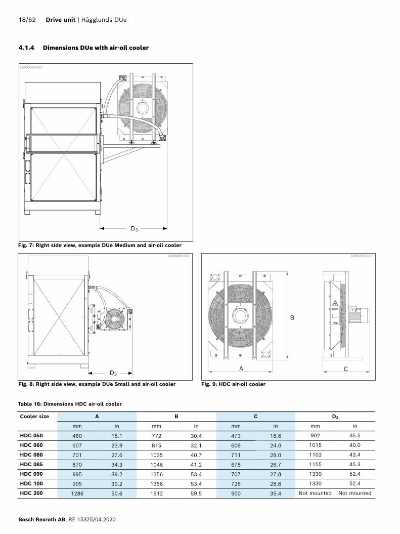
Fig. 7: Right side view, example DUe Medium and air-oil cooler
Cooler size A B C D3
mm in mm in mm in mm in
HDC 050 460 18.1 772 30.4 473 18.6 902 35.5
HDC 060 607 23.9 815 32.1 609 24.0 1015 40.0
HDC 080 701 27.6 1035 40.7 711 28.0 1103 43.4
HDC 085 870 34.3 1046 41.2 678 26.7 1155 45.3
HDC 090 995 39.2 1356 53.4 707 27.8 1330 52.4
HDC 100 995 39.2 1356 53.4 726 28.6 1330 52.4
HDC 200 1286 50.6 1512 59.5 900 35.4 Not mounted Not mounted
DD00089383
Table 16: Dimensions HDC air-oil cooler
D3
Fig. 8: Right side view, example DUe Small and air-oil cooler
B
C D3
Fig. 9: HDC air-oil cooler
DD00089384 DD00089385
A
4.1.4 Dimensions DUe with air-oil cooler
18/62 Drive unit | Hägglunds DUe
Bosch Rexroth AB, RE 15325/04.2020
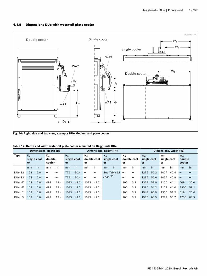
Table 17: Depth and width water-oil plate cooler mounted on Hägglunds DUe
Dimensions, depth (D) Dimensions, height (H) Dimensions, width (W)
Type D4
single cool-er
D4
double cooler
H5
single cool-er
H5
double cool-er
H6
single cool-er
H6
double cool-er
W6
single cool-er
W7
single cool-er
W8
double cooler
mm in mm in mm in mm in mm in mm in mm in mm in mm in
DUe S2 153 6.0 — — 772 30.4 — — See Table 32 page 30
— — 1275 50.2 1027 40.4 — —
DUe S3 153 6.0 — — 772 30.4 — — — — 1285 50.6 1037 40.8 — —
DUe M2 153 6.0 493 19.4 1073 42.2 1073 42.2 100 3.9 1368 53.9 1120 44.1 509 20.0
DUe M3 153 6.0 493 19.4 1073 42.2 1073 42.2 100 3.9 1377 54.2 1129 44.4 1500 59.1
DUe L2 153 6.0 493 19.4 1073 42.2 1073 42.2 100 3.9 1548 60.9 1300 51.2 519 20.4
DUe L3 153 6.0 493 19.4 1073 42.2 1073 42.2 100 3.9 1537 60.5 1289 50.7 1750 68.9
4.1.5 Dimensions DUe with water-oil plate cooler
Fig. 10: Right side and top view, example DUe Medium and plate cooler
DD00062539
D4
H6
H5
WA2
WA1
WA2
H6
WA1 H5
W6
W7
W8 Double cooler
Single cooler
D4
Single cooler Double cooler
Hägglunds DUe | Drive unit 19/62
RE 15325/04.2020, Bosch Rexroth AB

4.1.6 Dimensions DUe with water-oil tube cooler
Fig. 11: Right side view example DUe M2, cooler, size 400
Table 18: Depth and width water-oil tube cooler mounted on Hägglunds DUe
DD00064732
D5 D6
Dimensions, depth (D)
Type D5
Series mounted cooler
D6
Bracket for allsingle mounted cooler
E1
Tube cooler size 400
E1
Tube cooler size 600
mm in mm in mm in mm in
DUe S2 879 34.6 710 27.9 251 9.9 760 29.9
DUe S3 879 34.6 710 27.9 --- --- --- ---
DUe M2 879 34.6 710 27.9 163 6.4 676 26.6
DUe M3 879 34.6 710 27.9 --- --- --- ---
DUe L2 879 34.6 710 27.9 153 6.0 662 26.1
DUe L3 879 34.6 710 27.9 --- --- --- ---
D2
D1
Series cooler Single cooler
E1
Fig. 12: Hägglunds top view example DUe S2 series cooler size 400
20/62 Drive unit | Hägglunds DUe
Bosch Rexroth AB, RE 15325/04.2020
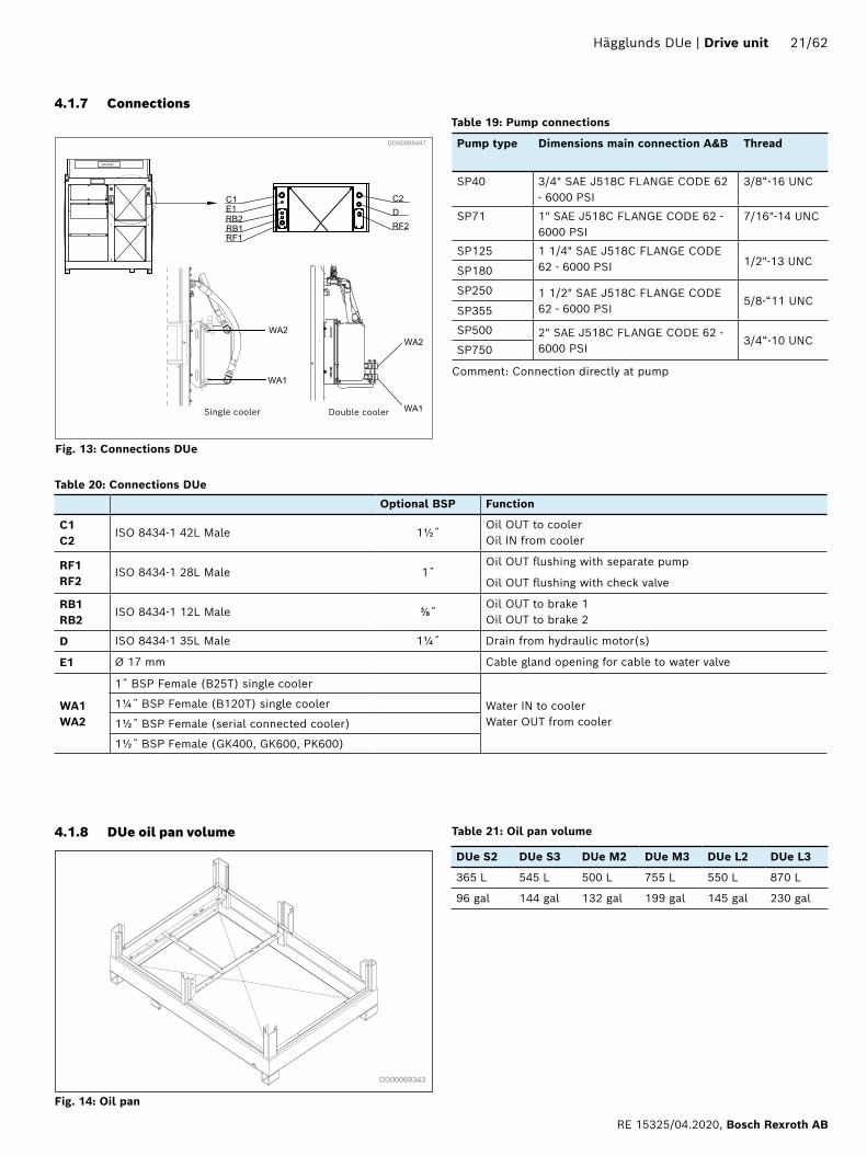
Single cooler Double cooler
Optional BSP Function
C1C2
ISO 8434-1 42L Male 1½˝Oil OUT to coolerOil IN from cooler
RF1 RF2
ISO 8434-1 28L Male 1˝Oil OUT flushing with separate pump
Oil OUT flushing with check valve
RB1RB2
ISO 8434-1 12L Male ⅜˝Oil OUT to brake 1Oil OUT to brake 2
D ISO 8434-1 35L Male 1¼˝ Drain from hydraulic motor(s)
E1 Ø 17 mm Cable gland opening for cable to water valve
WA1WA2
1˝ BSP Female (B25T) single cooler
Water IN to coolerWater OUT from cooler
1¼˝ BSP Female (B120T) single cooler
1½˝ BSP Female (serial connected cooler)
1½˝ BSP Female (GK400, GK600, PK600)
DUe S2 DUe S3 DUe M2 DUe M3 DUe L2 DUe L3
365 L 545 L 500 L 755 L 550 L 870 L
96 gal 144 gal 132 gal 199 gal 145 gal 230 gal
DD00069343
4.1.7 Connections
4.1.8 DUe oil pan volume
DD00089447
Fig. 13: Connections DUe
Fig. 14: Oil pan
Table 19: Pump connections
Pump type Dimensions main connection A&B Thread
SP40 3/4" SAE J518C FLANGE CODE 62 - 6000 PSI
3/8“-16 UNC
SP71 1" SAE J518C FLANGE CODE 62 - 6000 PSI
7/16"-14 UNC
SP125 1 1/4" SAE J518C FLANGE CODE 62 - 6000 PSI 1/2"-13 UNC
SP180
SP250 1 1/2" SAE J518C FLANGE CODE 62 - 6000 PSI
5/8-“11 UNCSP355
SP500 2" SAE J518C FLANGE CODE 62 - 6000 PSI
3/4“-10 UNCSP750
Comment: Connection directly at pump
Table 20: Connections DUe
Table 21: Oil pan volume
Hägglunds DUe | Drive unit 21/62
RE 15325/04.2020, Bosch Rexroth AB

4.2 Main components
4.2.1 Electric motor
Technical data
Fig. 15: Electric motor
Conditions, voltageThe motors can withstand a continuous voltage deviation of 5% and a maximum deviation of up to 10% for a short time.
Conditions, altitudeAmbient temperature: -20°C - +40°C (-4°F - +104°F).Altitude above sea level: 1000 m.
DD00068749
FunctionThe electric motor is a totally enclosed, fan cooled TEFC squirrel-cage, 4-pole 3-phase motor
If the Hägglunds DUe will be operating in damp enviroment, it is advised to use an anti condensation heater to reduce the risk of short circuit in the electric motor.The electric motors used as standard in the drive unit are manufactured by Siemens.
Output power3-500kW
Voltage Frequency
380 VD 50 Hz 440 VD 60 Hz400 VD / 690 VY 50 Hz 460 VD 60 Hz415 VD 50 Hz 480 VD 60 Hz
Table 22: Technical data electric motor
Operating Duty: S1
Method of mounting: B5/V1
Degree of protection: IP55 (Motor and conn.box)
Cooling form: IC411, fan cooler.
Insulation class: F/B
Motor protection: 3 PTC thermistors, 150ºC, in stator winding
Greasing: Grease nipples for bearing D and N side, Type H1, acc. to DIN 71412
Heater elements: 230 VAC
Painting: Corrosion class C3
Sound press. level Lp: ≤ 85 dB(A) acc. to IEC 60034-9
Table 23: Standards electrical motor
Standard IEC/EN 60034
EU Efficiency classes: According to IEC 60034-30,
3-500 kW, Efficiency class IE3.
Certificate: Type approval test certificate type 3.1 according to EN 10-204 (on request)
Standards
22/62 Drive unit | Hägglunds DUe
Bosch Rexroth AB, RE 15325/04.2020

D and Y -connectionsThe three windings of the motor can be connected inside the terminal box to the three phase supply net in two different ways, Y-(star-) or D-(∆-) connection.
Y -connectionD -connection
Fig. 16: D and Y connections
DD00062668
Fig. 17: Hydraulic symbol
Fig. 18: Electrical symbol
DD00062681 Fig. 19: Electrical symbol (thermistor)
DD00066345
DD00066347
Hägglunds DUe | Drive unit 23/62
RE 15325/04.2020, Bosch Rexroth AB

4.2.2 Main pump SP
Fig. 20: Pump SP size 40 to 180 Fig. 21: Pump SP size 250 to 750
DD00065517 DD00065554
Functions Variable displacement axial piston pump of swashplate design for hydrostatic closed circuit transmissions• Flow is proportional to speed and displacement
and is infinitely variable through adjustment of the swivel angle
• Output flow increases with swivel angle from 0 to its maximum value
• Swivelling the pump over centre smoothly changes the direction of flow
• A highly adaptable range of control and regulating devices are available
• The pump is equipped with two pressure relief valves on the high pressure ports to protect the hydrostatic transmission (pump and motor) from overloads
• One common pump for charge and EP displacement control
• Compact overall design• Low noise level• Long service life• High efficiency• Throughdrive for multiple pump combinations also
possible with integrated charge pump up to 100%• SP pumps can be tandem mounted to the same
electric motor in combinations according to Table 2
Charge pump and control valves • Auxillary for SP 40 to SP 180• Integrated for SP 250 to SP 750
24/62 Drive unit | Hägglunds DUe
Bosch Rexroth AB, RE 15325/04.2020

Table 24: Operating pressure range, according to DIN 24312
Inlet operating pressure bar
Required static charge pressure (MK4), pc min 15
Heavy duty pressure, pc max 20
Static charge pressure (short periods), relief valve setting, pc min. Min.
8
Static charge pressure, pc max. Max. 20
Dynamic charge pressure (fluctuations) Min. 4
Dynamic charge pressure (fluctuations) Max. 40
Inlet pressure at port S1 (auxiliary pump) Ps. Min. ≥ 0,8 bar abs
Inlet pressure at port S1 (auxiliary pump) Ps. Max. 2
Outlet operating pressure, variable pumpPressure at port A or B
bar
Nominal pressure pN 350
Peak pressure pmax 400
Case drain pressureMax. case pressure (housing pressure):
bar
pL continous 5
PL max 8
*T1 ,T2 and T3 must be unloaded to tank.
*Only for SP 40 - SP 180
Operating pressure rangeDepending on the behaviour of the transmitted hydraulic energy in the system, charge pressure fluctuations can occur. In order to prevent damage to the system, charge pressure protection, which monitors the static charge pressure part is necessary. Port MK4 is suitable to monitor the charge pressure. It is recommended to check regularly the charge pressure for the permissible max. and min. spikes with suitable measuring equipment.
In order to prevent excessive charge pressure spikes, a low pressure accumulator can be connected to port K4. Accumulator sizing as well as the selection for the best connecting location depend on the system behaviour and the operating conditions under consideration of the available charge flow. Depending on the total systems leakage flow, it may be necessary to increase the charge flow by means of a larger or additional charge pump, see Inlet pressure at port S1 (auxiliary pump).
EP - Electro-hydraulic control with proportional solenoid
The EP control adjusts the pump displacement proportional to the solenoid current. The pump displacement is therefore step-less variable. One proportional solenoid is assigned to each direction of flow.
Operating voltage: 24 VNominal current: 800 mACurrent range 210...740 mANominal resistance at 20 °C: 21 Ω
Fig. 22: EP, hydraulic control
DD00063446
Hägglunds DUe | Drive unit 25/62
RE 15325/04.2020, Bosch Rexroth AB

Table 25: Ports
Ports Description Ports Description
A, B Pressure port ME, ME3 Test points charge pressure
S Inlet port K4 Accumulator port
MA1, MA2, MB1, MB2 Test points operating press. MK4 Test point charge pressure
T, K2, K3 Oil drain port M1, M2 Test point control pressure
E1 Brake function XA2, XB2, XAB Ports for remote pressure pilot valves
K1 Return flow T1, T3 Ports for unloading of high pressure relief valves and charge pressure relief valve.
T(D) Measure point T2 Port for unloading of shaft seal
U Bearing flushing port/air bleed port
Charge pressure relief valve
Crossover relief valves/High pressure relief valves
Control pressure relief valve
Pressure control valve A
Flushing valve
Bypass valve
Pressure control valve B
Pressure compensator adjustment
Mounted charge pump
Hydraulic circuit
Check valves charge flow
Electro-hydraulic control with proportional solenoid and remote pressure control
D00065863
Fig. 23: Principal hydraulic circuit for SP pump size 40-180
26/62 Drive unit | Hägglunds DUe
Bosch Rexroth AB, RE 15325/04.2020

Table 26: Ports
Port Description Port Description
A, B Pressure ports ME3 Measuring port ex. charge pressure
S Inlet port MK4 Measuring port flushing pressure
E1 To charge filter (optional) M1, M2 Measuring ports control pressure
E2 From charge filter (optional) T(D) Measure point
E3 External charge port T, K2, K3 Oil drain port
K1 Return flow T1 Drain port pressure relief valve
K4 Accumulator port U Bearing flushing port/air bleed port
MA, MB, MAB Measuring ports operating pressure XA2, XB2, XAB Pilot port pressure control
MS Measuring port inlet pressure
Charge pressure relief valve
Flushing valve
Crossover relief valves/ High pressure relief valve
Bypass valve
Check valves charge flow
Control pressure relief valve
Integrated charge pump
EP Electr.-hydr. control with prop. solenoids and remote pressure control
Pressure compensator adjustment
Fig. 24: Principal hydraulic circuit for SP pump size 250-750
DD00108957
Hägglunds DUe | Drive unit 27/62
RE 15325/04.2020, Bosch Rexroth AB

Technical dataTable 27: Technical data SP 40-180
Size 40 71 125 180
Displacement Variable pump V g max cm3 40 71 125 180
Auxiliary pump V g H cm3 20 25 38 45
Speed max. speed n max rpm 3 000 3 000 2 600 2 400
min. speed n min rpm 500 500 500 500
Flow at nmax o v max l/min 120 213 325 432
at nE=1500 rpm l/min 60 107 188 270
Power, max. at (Dp=350 bar) at n o max P o max kW 86 132 190 252
at nE=1500 rpm kW 35 62 109 158
Torque at V g max Dp=350 bar T max Nm 223 395 696 1 002
Variable pump (without aux.pump) Dp=100 bar T Nm 64 113 199 286
Moment of inertia about drive axis J kgm2 0.0049 0.0121 0.03 0.055
Case volume l 2 2,5 5 4
Table 28: Technical data SP 250-750.
Size 250 355 500 750
Displacement variable pump Vg max cm3 250 355 500 750
charge pump Vg max cm3 63 80 98 143
Speed max. speed nmax min-1 2 200 2 000 1 800 1 600
min. speed nmin min-1 800 800 800 800
Flow at nmax qV max l/min 550 710 900 1 200
at nE=1500 min-1 qVE max l/min 375 533 750 1 125
Power , max. at (Dp = 350 bar) at n max P max kW 321 414 525 700
at nE=1500 min-1 PE max kW 219 311 438 656
Torque at Vg max Dp = 350 bar Tmax Nm 1 391 1 976 2 783 4 174
Variable pump (without aux. pump) Dp = 100 bar T Nm 398 564 795 1 193
Moment of inertia about drive axis J kgm2 0.0959 0.19 0.3325 0.66
Case volume l 10 8 14 19
28/62 Drive unit | Hägglunds DUe
Bosch Rexroth AB, RE 15325/04.2020

Size Flushing flow, qfl l/min
40 3
71 4
125 5
180 7
250 10
355 15
500 20
750 30
Size Installed electric motor power, kW
Installed electric motor power, hp
40 50 67
71 69 93
125 108 145
180 133 178
250 186 249
355 242 324
500 303 406
750 445 597
Table 29: Recommended flushing flows
Table 30: Installed electric motor power when flushing is needed
Bearing flushingFor the following operating conditions bearing flushing is required for reliable continuous operation:• Applications with special fluids (non mineral oils),
due to limited lubricity and narrow operating temperature range
• Operation with critical conditions of temperature and viscosity with mineral oil
Flushing is carried out via U-port, which is located in the front flange area of the pump. The flushing oil flows through the front bearing and leaves the system together with the leakage oil at the case drain port.
Recommended flushing flows for the various pump sizes: These flushing flows create a pressure drop of approximately 3 bar between U-port and pump housing (including fitting).
Note. When using bearing flushing at U-port the throttle screw, which can be found at U-port, has to be turned in all the way to the stop.
Charge pressure and control valves
High pressure relief valvesTwo pilot operated relief valves that prevent pump damage from excessive pressure levels. Each pressure side has its own relief valve, which is vented to the low pressure side of the loop.
Charge pressure relief valveThe charge pressure relief valve is direct operated. T1 needs external drain. Setting pressure range: 12-21 bar (174-305 psi).Standard setting 15 bar (218 psi).
Control pressure relief valve Control pressure relief valve is direct operated with unloading function.Setting pressure range: 30-45 bar (435-653 psi)Normal setting range: 35-42 bar (508-610 psi) depending on pump size.
Hägglunds DUe | Drive unit 29/62
RE 15325/04.2020, Bosch Rexroth AB
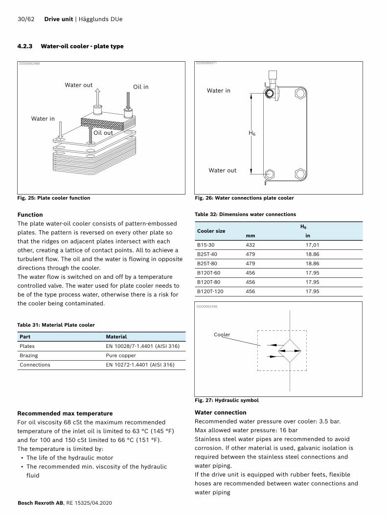
Oil in
4.2.3 Water-oil cooler - plate type
DD00062496
DD00062486
FunctionThe plate water-oil cooler consists of pattern-embossed plates. The pattern is reversed on every other plate so that the ridges on adjacent plates intersect with each other, creating a lattice of contact points. All to achieve a turbulent flow. The oil and the water is flowing in opposite directions through the cooler. The water flow is switched on and off by a temperature controlled valve. The water used for plate cooler needs to be of the type process water, otherwise there is a risk for the cooler being contaminated.
Water in
Oil out
Water out
Fig. 25: Plate cooler function
Part Material
Plates EN 10028/7-1.4401 (AISI 316)
Brazing Pure copper
Connections EN 10272-1.4401 (AISI 316)
Recommended max temperatureFor oil viscosity 68 cSt the maximum recommended temperature of the inlet oil is limited to 63 °C (145 °F) and for 100 and 150 cSt limited to 66 °C (151 °F).The temperature is limited by:• The life of the hydraulic motor• The recommended min. viscosity of the hydraulic
fluid
Table 31: Material Plate cooler
Fig. 26: Water connections plate cooler
Cooler
Cooler sizeH6
mm in
B15-30 432 17,01
B25T-40 479 18.86
B25T-80 479 18.86
B120T-60 456 17.95
B120T-80 456 17.95
B120T-120 456 17.95
Water in
Water out
Fig. 27: Hydraulic symbol
H6
Table 32: Dimensions water connections
Water connectionRecommended water pressure over cooler: 3.5 bar. Max allowed water pressure: 16 barStainless steel water pipes are recommended to avoid corrosion. If other material is used, galvanic isolation is required between the stainless steel connections and water piping.If the drive unit is equipped with rubber feets, flexible hoses are recommended between water connections and water piping
DD00089371
30/62 Drive unit | Hägglunds DUe
Bosch Rexroth AB, RE 15325/04.2020

Influence of water composition on corrosion resistanceThe guide below is to give a picture of the corrosion resistance of stainless steels and brazing materials in tap water at room temperature.
Explanations: + = Good resistance under normal conditions 0 = Corrosion problems may occur especially when more factors are valued 0 - = Use is not recommended
Table 33: Acceptable water chemical content
Water content Concentration (mg/l or ppm)
Time limits Analyze before
AISI 316 Copper
Alkalinity (HCO3) < 70 70-300 > 300
Within 24 h + ++
0+
=/+
Sulfate * (SO42) < 70 70-300 > 300
No limit + + +
+0/--
HCO3 / SO42 < 1.0 > 1.0
No limit + +
+0/-
Electrical conductivity < 10 μS/cm 10-500 μS/cm > 500 μS/cm
No limit + + +
0+0
pH ** < 6.0 6.0-7.5 7.5-9.0 > 9.0
Within 24 h 0 + ++
00+0
Ammonium (NH4+) < 2 2-20 > 20
Within 24 h + + +
+ 0-
Chlorides (Cl) at 60° At 80° the Cl value is limited to 150 ppm.
< 100 100-200 200-300 > 300
No limit + + +-
+ ++
0/+
Free chlorine (Cl2) < 1 1-5 > 5
Within 5 h +--
+ 0
0/-
Hydrogen sulfide (H2S) < 0.05 > 0.05
No limit + +
+0/-
Free (aggressive) carbon dioxide (CO2) < 5 5-20 > 20
No limit + + +
+ 0-
Total hardness (°dH) 4.0-8.5 No limit + +
Nitrate * (NO3) < 100 > 100
No limit + +
+0
Iron *** (Fe) < 0.2 > 0.2
No limit + +
+ +
Aluminium (Al) < 0.2 > 0.2
No limit + +
+0
Manganese *** (Mn) < 0.1 > 0.1
No limit + +
+0
* Sulfates and nitrates works as inhibitors for pitting corrosion caused by chlorides in pH neutral environments ** In general low pH (below 6) increase corrosion risk and high pH (above 7.5) decrease the corrosion risk *** Fe3+ and Mn4+ are strong oxidants and may increase the risk for localised corrosion on stainless steels SiO2 above 150 ppm increase the risk of scaling
Hägglunds DUe | Drive unit 31/62
RE 15325/04.2020, Bosch Rexroth AB

4.2.4 Water-oil cooler - tube type
Fig. 28: Tube cooler
DD00065480
FunctionThe tube water-oil cooler consists of several tubes in a tubestack for heat exchange. The tube cooler is easy to clean and it is suitable for contaminated water. The oil and water is flowing in opposite directions. The water flow is switched on and off by a temperature controlled valve.
DD00062496
Fig. 29: Hydraulic symbol
Chemical Level
Free Chlorine 1.0 - 3.0 ppm
Calcium Hardness 200 - 400 ppm
pH 7.2 -7.8
Alkalinity 100 - 150 ppm
Bromine 2.0 - 4.0 ppm
Chloride > 150 ppm
Recommended max temperatureFor oil viscosity 68 cSt the maximum recommended temperature of the inlet oil is limited to 63 °C (145 °F) and for 100 and 150 cSt limited to 66 °C (151 °F).The temperature is limited by:• The life of the hydraulic motor• The recommended min. viscosity of the hydraulic
fluid
Part Material
Housing: Aluminium
End cover: Cast iron
Tube stack: 90/10 Cu.NI
Table 34: Material tube cooler
Table 35: Acceptable water chemical content
Water connectionRecommended water pressure over cooler: 3.5 bar. Max allowed water pressure: 16 barStainless steel water pipes are recommended to avoid corrosion. If other material is used, galvanic isolation is required between the stainless steel connections and water piping.If the drive unit is equipped with rubber feets, flexible hoses are recommended between water connections and water piping
32/62 Drive unit | Hägglunds DUe
Bosch Rexroth AB, RE 15325/04.2020

4.2.5 Hägglunds HDC cooler (air-oil cooler)
Function• The air-oil cooler consists of a fan driven by an
electric motor, blowing air through the cooler matrix.• The cooling pipes are made by extruded aluminium
sections. They are flat with narrow short sides to expose a maximum heat-emitting area and to allow low air pressure drop.
• The electric motor is a 3-phase asynchronous motor.• An 8 bar bypass valve is always installed inside the
DUe between the inlet and outlet of the cooler. An extra bypass valve is mounted directly on the cooler under following conditions -When the cooler is mounted separately and the ambient temperature is below 0°C. -When the cooler is mounted on the unit and the ambient temperature is below -20°C ,
Electric motor:• Insulation: Class F• Temperature rise: Class B• Protection standard: IP55
Table 36: Oil volume
Cooler Type Oil volume of the cooler
l gal
HDC 050 5.7 1.51
HDC 060 8.7 2.30
HDC 080 17.7 4.68
HDC 085 15.5 4.09
HDC 090 28.6 7.56
HDC 100 32.7 8.64
HDC 200 54.8 14.48
Recommended max temperatureFor oil viscosity 68 cSt the maximum recommended temperature of the inlet oil is limited to 63 °C (145 °F) and for 100 and 150 cSt limited to 66 °C (151 °F).The temperature is limited by:• The life of the hydraulic motor• The recommended min. viscosity of the hydraulic
fluid
Fig. 30: Hydraulic symbolDD00062721
Note!When the air-oil cooler is separated from the Power unit, the pressure drop through the piping hoses is not allowed to exceed 1 bar (14 psi). Always applicable for size HDC 200.
Table 37: Material types
Part Material
Matrix Aluminum
Fan blades Nylon PAG
Fan housing Steel
Fan guard Steel
Electric motor Aluminum
Other parts Steel
Coating Painted black RAL 9005
DD00062500
Fig. 31: Hägglunds HDC cooler
Mechanical data
Hägglunds DUe | Drive unit 33/62
RE 15325/04.2020, Bosch Rexroth AB

Voltage (V) Frequency (Hz)
380 50
400 50
440 60
460 60
Fig. 32: Electrical symbolDD00066437
Table 38: Ordering code HDC cooler and electric motor data / sound data
HDC cooler, electric motor data / sound data
Electrical data
Table 39: Rated data electric motors
Cooler ordering code
Driving power (kW) Noise Max perm.dynamic pressure Max. perm.static pressure
50 Hz 60 Hz dBA bar psi bar psi
HDC 050-4 0.37 0.43 78 14 203 26 377
HDC 060-4 0.75 0.90 78 14 203 26 377
HDC 080-4 1.5 1.8 78 14 203 26 377
HDC 085-6 2.2 2.6 78 14 203 21 305
HDC 090-6 2.2 2.6 85 14 203 21 305
HDC 100-6 2.2 2.6 87 14 203 21 305
HDC 100-4 7.5 9.0 97 14 203 21 305
HDC 200-6 7.5 9.0 92 14 203 21 305
HDC 200-4 18.5 22.2 100 14 203 21 305
34/62 Drive unit | Hägglunds DUe
Bosch Rexroth AB, RE 15325/04.2020

01 02 03 04 05 06 07 08 09 10 11 12
HDC 200 - A 6 G 01 - 20 - 40 - 0 - 1 - 4 - 00
Ordering codeIn order to identify Hägglunds equipment, the following ordering code is used.
Example Hägglunds HDC200
01 Hägglunds air-oil cooler
HDC
02 Cooler size
20 020
30 030
50 050
60 060
80 080
85 085
90 090
100 100
200 200
03 Cooling media
Air A
04 Number of poles, electric motor
4-pole 4
6-pole 6
8-pole 8
05 Electric motor type/voltage
230V 50Hz A
380V 50Hz B
400V 50Hz C
415V 50Hz D
415V 50Hz (355-455V) (47-53Hz) E
460V 50Hz F
500V 50Hz G
525V 50Hz H
550V 50Hz I
660V 50Hz J
690V 50Hz K
440V 60Hz L
460V 60Hz M
480V 60Hz N
Special electric motor Z
Hägglunds DUe | Drive unit 35/62
RE 15325/04.2020, Bosch Rexroth AB

06 Motor output
0,18 kW 50Hz 00
0,37 kW 50Hz 01
0,75 kW 50Hz 02
1,5 kW 50Hz 03
2,2 kW 50Hz 04
3 kW 50Hz 05
4 kW 50Hz 06
5,5 kW 50Hz 07
7,5 kW 50Hz 08
11 kW 50Hz 09
18,5 kW 50Hz 10
22 kW 50 Hz 11
30 kW 50 Hz 12
0,21 kW 60Hz 20
0,43 kW 60Hz 21
0,9 kW 60Hz 22
1,8 kW 60Hz 23
2,6 kW 60Hz 24
3,6 kW 60Hz 25
4,8 kW 60Hz 26
9,0 kW 60Hz 27
13,2 kW 60Hz 28
22,2 kW 60Hz 29
07 Ambient temperature min
-20°C (Standard) 20
-30°C 30
-40°C 40
-45°C 45
08 Ambient temperature max
+40°C (Standard) 40
+45°C 45
+50°C 50
09 Heater
None (Standard) 0
Space heater S
10 Altitude (A)
A < 1000 m (standard) 1
1000 m < A < 2000 m 2
2000 m < A < 3000 m 3
3000 m < A < 4000 m 4
4000 m < A < 4500 m 5
4500 m < A < 5000 m 6
11 Cooler matrix
Without bypass (Standard) 0
4 bar bypass 4
12 Special design
Standard 00
Special index 01-99 01
36/62 Drive unit | Hägglunds DUe
Bosch Rexroth AB, RE 15325/04.2020

Table 40: Tank volume
Frame variant/version Tank volume (l)
Small / 2 compartments 120, 255
Small /3 compartments 120, 255, 350
Medium /2 compartments 120, 255, 350, 505
Medium /3 compartments 120, 255, 350, 505, 765
Large /2 compartments 120, 255, 350, 505
Large /3 compartments 255, 350, 505, 765, 835
4.2.6 Tank
Table 41: Material
Part Material
Tank Stainless steel 1.4301
Fluid level gauge
Lens Polyamid
Lens base Nylon
Shroud Polystyrene
Fluid level temperature gaugeThe fluid level gauge is resistant to mineral and petroleum based fluids.
StandardsWelding according to SS-ISO 5817
DD00066149
Fig. 33: Tank
Mechnical data
Function The tank contains cooled clean oil for the continous oil exchange in the hydraulic system.The tank is welded of stainless steel plates. In the drive unit the tank supplies up to four pumps. The tank volume has a ratio of minimum 1:1 to the exchange demand of the drive unit.
The tank is equipped with:• Visual level gauge• Suction valve with position switch• Level sensor• Temperature sensor • Drain tap• Filling point with quick release coupling.(oil filling
via drain filter)• Air breather filter • Oil heater (option)• Bladder (option)• Inspection cover (option).• Leveling pipe connection (option)
Leakage test by supplier:Air pressure 0,2 bar, max 0,3 bar inside tank.Soap water are sprayed at the weldings outside the tank and check for leakage.
Hägglunds DUe | Drive unit 37/62
RE 15325/04.2020, Bosch Rexroth AB

Table 42: Technical data, filters
Part Single/Duplex
Filter complete: Filter head Low pressure Aluminum alloy
Medium pressure Ductile cast iron
Filter bowl Low pressure Aluminum
Medium pressure Steel
Seals Nitrile rubber
Max pressure Low pressure 25 bar (360 psi)
Medium pressure 210 bar (3 050 psi)
Bypass pressure Δp Low pressure 3.5 bar (50 psi) + 10%
Medium pressure 7 bar (100 psi) + 10%
Max flow Size 250 250 l/min (66 gpm)
Size 400 400 l/min (106 gpm)
Size 600 600l/min (160 gpm)
Filter element: Filtration grade 10 µm (standard)
6 µm (optional)
Filter Synthetic glass fibre material
End shields Sn plated
Inside tube Sn plated
Antistatic layer Optional
Mechnical data
The filter elements are β-stable (Fig. 35), has a multi layered structure and are compatible with HFA , HFB and HFC fluids. The opening pressure for the by-pass valve ∆P = 3.5 bar (50.8 psi) + 10%.
The β-ratio for the particle size 10 (μm) fullfills ISO 4572 (β10 ≥ 75).
StandardsFilter and filter elements according to DIN 24550
Separation characteristics
Fig. 34: Oil filter
4.2.7 Oil filterDD00070464
DD00082286
Fig. 35: Separation characteristics
Single Duplex
FunctionThe filters are used in drain and return lines. The filter housing is equipped with bypass valve and an electrical and visual contamination indicator. The oil flow through the filter is according to the picture above. Single (standard) or duplex (option) filters can be selected. There is a contamination indicator that gives indication if the differential pressure is above 2.2 bar (31.9 psi) - 10% and the temperature of the oil is above 30 °C (86 °F). A single filter has one filter element and a duplex filter has two filter elements but only one filter is used at any one time. On duplex filters the filter elements can easily be replaced without interrupting operation.
38/62 Drive unit | Hägglunds DUe
Bosch Rexroth AB, RE 15325/04.2020
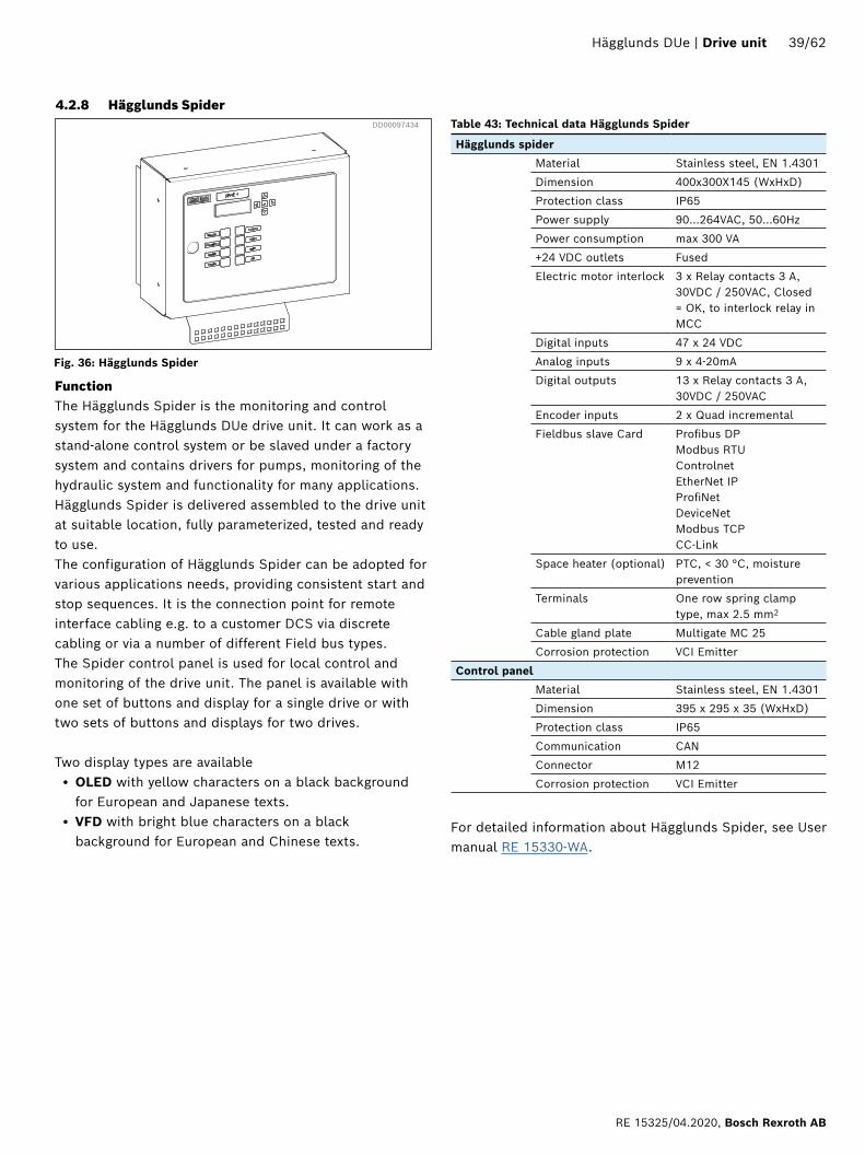
4.2.8 Hägglunds Spider DD00097434
Fig. 36: Hägglunds Spider
FunctionThe Hägglunds Spider is the monitoring and control system for the Hägglunds DUe drive unit. It can work as a stand-alone control system or be slaved under a factory system and contains drivers for pumps, monitoring of the hydraulic system and functionality for many applications. Hägglunds Spider is delivered assembled to the drive unit at suitable location, fully parameterized, tested and ready to use.The configuration of Hägglunds Spider can be adopted for various applications needs, providing consistent start and stop sequences. It is the connection point for remote interface cabling e.g. to a customer DCS via discrete cabling or via a number of different Field bus types. The Spider control panel is used for local control and monitoring of the drive unit. The panel is available with one set of buttons and display for a single drive or with two sets of buttons and displays for two drives.
Two display types are available• OLED with yellow characters on a black background
for European and Japanese texts.• VFD with bright blue characters on a black
background for European and Chinese texts.
Table 43: Technical data Hägglunds Spider
Hägglunds spider
Material Stainless steel, EN 1.4301
Dimension 400x300X145 (WxHxD)
Protection class IP65
Power supply 90…264VAC, 50…60Hz
Power consumption max 300 VA
+24 VDC outlets Fused
Electric motor interlock 3 x Relay contacts 3 A, 30VDC / 250VAC, Closed = OK, to interlock relay in MCC
Digital inputs 47 x 24 VDC
Analog inputs 9 x 4-20mA
Digital outputs 13 x Relay contacts 3 A, 30VDC / 250VAC
Encoder inputs 2 x Quad incremental
Fieldbus slave Card Profibus DP Modbus RTU Controlnet EtherNet IP ProfiNet DeviceNet Modbus TCP CC-Link
Space heater (optional) PTC, < 30 °C, moisture prevention
Terminals One row spring clamp type, max 2.5 mm2
Cable gland plate Multigate MC 25
Corrosion protection VCI Emitter
Control panel
Material Stainless steel, EN 1.4301
Dimension 395 x 295 x 35 (WxHxD)
Protection class IP65
Communication CAN
Connector M12
Corrosion protection VCI Emitter
For detailed information about Hägglunds Spider, see User manual RE 15330-WA.
Hägglunds DUe | Drive unit 39/62
RE 15325/04.2020, Bosch Rexroth AB

4.2.9 Hägglunds ICp Pump control
FunctionThe Hägglunds ICp pump control is an alternative to Spider for controlling the pump. The solenoid coils of each pump in the drive unit is connected to an ICp unit. The pumps can be controlled without feedback, using the ICp as an amplifier or locked into closed loop control using either work pressure or swash angle as input. Configuration of ICp is done via Bluetooth and the Hägglunds ICp app is available for both android and iOS.
Table 44: Technical data Hägglunds ICp
Dimension 111x310x31 (WxHxD)
Protection class IP67
Power supply +24VDC(18-30)
Power consumption Max 60VA
+24V outlets Fused 100mA
Digital inputs 12 x 24VDC
Analog inputs 6 x 4-20 mA, 1 x PT100
Digital outputs 8 x 24VDC, 800mA
Contacts M12
Wireless connection Bluetooth low energy
For detailed information about Hägglunds ICp, see data sheet RE 15422.
Fig. 37: Hägglunds ICp pump control
DD00097432
40/62 Drive unit | Hägglunds DUe
Bosch Rexroth AB, RE 15325/04.2020
Mechnical data
Electrical data
4.3 Other components
4.3.1 Water valve
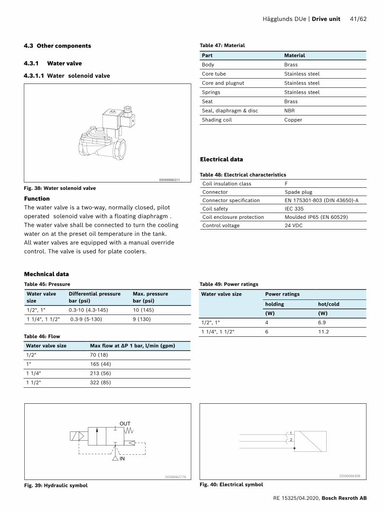
FunctionThe water valve is a two-way, normally closed, pilot operated solenoid valve with a floating diaphragm .The water valve shall be connected to turn the cooling water on at the preset oil temperature in the tank.All water valves are equipped with a manual override control. The valve is used for plate coolers.
4.3.1.1 Water solenoid valve
DD00066311
Fig. 38: Water solenoid valve
DD00066358DD00062779
Fig. 39: Hydraulic symbol Fig. 40: Electrical symbol
Table 45: Pressure
Table 46: Flow
Table 47: Material
Table 48: Electrical characteristics
Table 49: Power ratings
Water valve size
Differential pressure bar (psi)
Max. pressure bar (psi)
1/2", 1" 0.3-10 (4.3-145) 10 (145)
1 1/4", 1 1/2" 0.3-9 (5-130) 9 (130)
Water valve size Max flow at ΔP 1 bar, l/min (gpm)
1/2" 70 (18)
1" 165 (44)
1 1/4" 213 (56)
1 1/2" 322 (85)
Part Material
Body Brass
Core tube Stainless steel
Core and plugnut Stainless steel
Springs Stainless steel
Seat Brass
Seal, diaphragm & disc NBR
Shading coil Copper
Coil insulation class F
Connector Spade plug
Connector specification EN 175301-803 (DIN 43650)-A
Coil safety IEC 335
Coil enclosure protection Moulded IP65 (EN 60529)
Control voltage 24 VDC
Water valve size Power ratings
holding hot/cold
(W) (W)
1/2", 1" 4 6.9
1 1/4", 1 1/2" 6 11.2
Hägglunds DUe | Drive unit 41/62
RE 15325/04.2020, Bosch Rexroth AB

4.3.1.2 Water ball valve
DD00066313
Fig. 41: Water ball valve
Fig. 42: Electrical symbol
DD00066356
Fig. 43: Hydraulic symbol
DD00066590
FunctionThe water valve for tube cooler is a two-way ball valve manoeuvred by an electric actuator.The water valve will turn the cooling water at the preset oil temperature in the tank.The water valve is equipped with a manual override control and visual position.The valve is used for tube coolers.
Mechanical data
Size Max pressure
1 ½” 10 bar (145 psi)
Table 50: Ball valve
Table 51: Electric actuator
Enclosure IP67 Nema 4 and 6
Ambient temp -20°C to +70°C
Limit switches Open/Close, 2+2 pcs
Travel Angle 90°±5°
Weight 2.8 kg
Opening time 90° 17/14 sek (50/60Hz)
Table 52: Material
Part Material
Valve Body CF8M
Ball SS316
Seat CTFE
Electric actuator Steel, Aluminum and Al Bronze
Electrical data
Conduit Entries: M20 x 1,5Space Heater: 5W (110/230VAC & 24VDC)Anti-condensation
Control voltagesTwo different voltages are available for the water valve
Table 53: Supply
Voltage Max Current
110 VAC 0.35 A
230 VAC 0.23 A
Table 54: Connection
Terminal Function
1 Neutral
2 Heater 5 W
3 Close
4 Opened
5 PE
42/62 Drive unit | Hägglunds DUe
Bosch Rexroth AB, RE 15325/04.2020
Max. voltage Max. cont. current Max. switch on current
400 VAC 6 A 16 A
Part Material
Cage, valve Aluminium
Shifter Aluminium
Seals Nitrile rubber
Valve, other parts Steel galvanized
Cage and lifter, limit switch Thermoplast glass-fibre reinforced
Item Standard
Construction DIN-EN 50047
Electrical safety VDE 0113
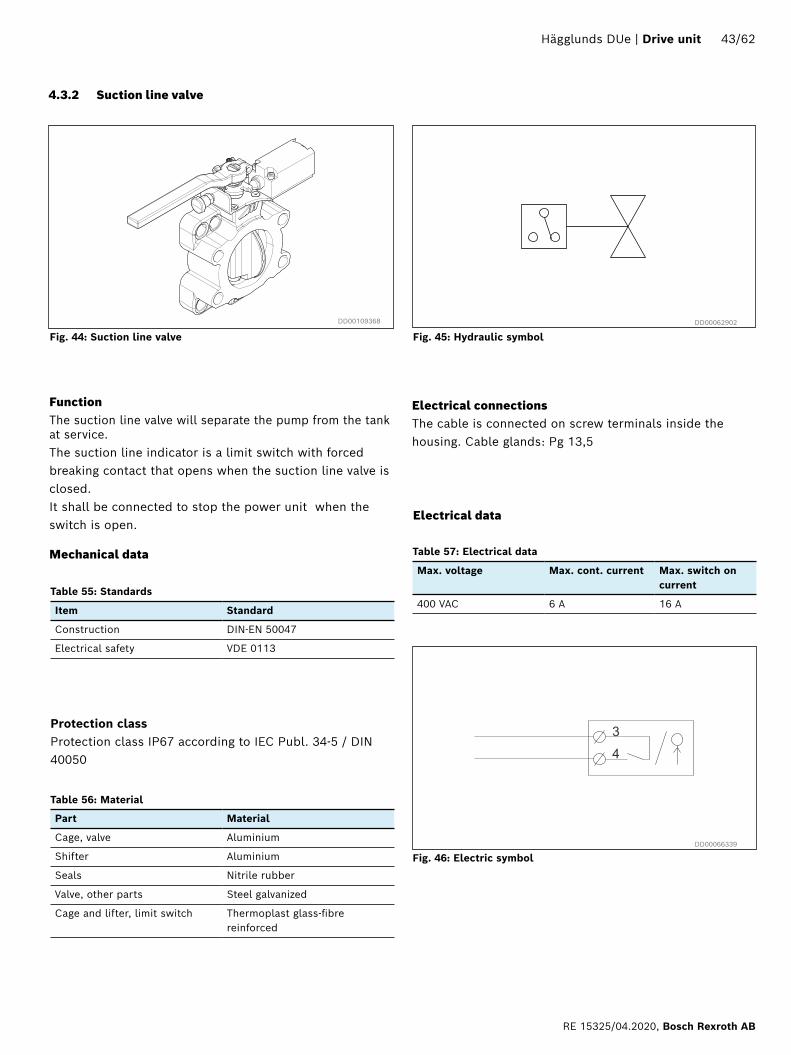
4.3.2 Suction line valve
Protection classProtection class IP67 according to IEC Publ. 34-5 / DIN 40050
Electrical data
Electrical connectionsThe cable is connected on screw terminals inside the housing. Cable glands: Pg 13,5
Fig. 44: Suction line valve
DD00066339
DD00062902
Table 55: Standards
Table 56: Material
Table 57: Electrical data
FunctionThe suction line valve will separate the pump from the tank at service. The suction line indicator is a limit switch with forced breaking contact that opens when the suction line valve is closed.It shall be connected to stop the power unit when the switch is open.
Mechanical data
Fig. 45: Hydraulic symbol
Fig. 46: Electric symbol
DD00109368
Hägglunds DUe | Drive unit 43/62
RE 15325/04.2020, Bosch Rexroth AB
Switch type normally closed
Indication Mechanical
Switching voltage nominal 24 VDC max 48 VDC
Max. switching power with resitive load
20 VA/20 W
Cold start supression 30°C, rising
20°C, falling
Table 58: Clogging indicator
Material Lower section Aluminum alloy, Steel
Upper section Polyamid
Seals Nitrile rubber
Max. operating pressure 420 bar
Temperature range -10°C ... +100°C (50°F...212 °F)
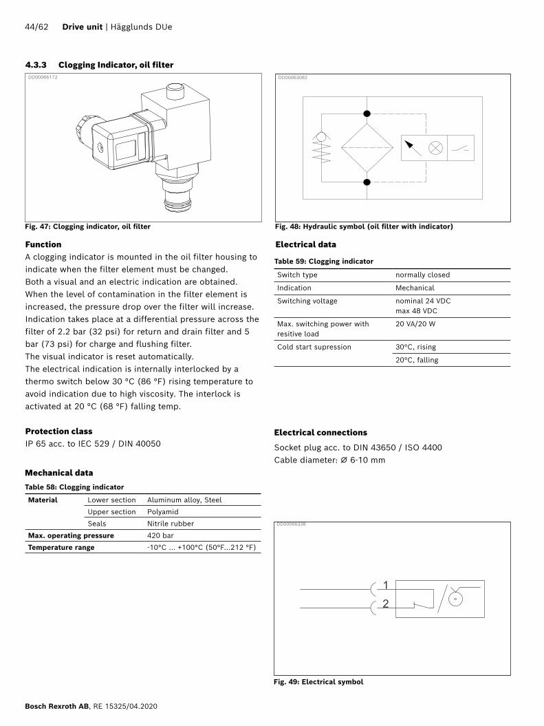
4.3.3 Clogging Indicator, oil filter
Electrical connections
Socket plug acc. to DIN 43650 / ISO 4400Cable diameter: ⌀ 6-10 mm
Fig. 47: Clogging indicator, oil filter
DD00066172 DD00063082
Electrical data
Table 59: Clogging indicator
Mechanical data
Fig. 48: Hydraulic symbol (oil filter with indicator)
Fig. 49: Electrical symbol
FunctionA clogging indicator is mounted in the oil filter housing to indicate when the filter element must be changed. Both a visual and an electric indication are obtained. When the level of contamination in the filter element is increased, the pressure drop over the filter will increase. Indication takes place at a differential pressure across the filter of 2.2 bar (32 psi) for return and drain filter and 5 bar (73 psi) for charge and flushing filter.The visual indicator is reset automatically.The electrical indication is internally interlocked by a thermo switch below 30 °C (86 °F) rising temperature to avoid indication due to high viscosity. The interlock is activated at 20 °C (68 °F) falling temp.
Protection classIP 65 acc. to IEC 529 / DIN 40050
DD00066338
44/62 Drive unit | Hägglunds DUe
Bosch Rexroth AB, RE 15325/04.2020

FunctionThe air breathing of the tank is via an air filter element to prevent contamination of the oil by particles in the air. The breather filter consists of a housing which is screwed onto the oil tank and a built-in filter element.
Mechanical dataTable 60: Material, Air breather filter
Filter Standard For bladder
Filtration rating 3 μm (absolute)
Check/bypass valve: No Yes Δp at 0.2 bar
Clogging indicator No
Temperature range -30 °C or +100 °C
Material Hose Steel, zinc-plated/plastic coated
Filter element Paper fiber
Seal NBR (Nitrile)
Tread G3/4˝
Additional attributes Anti-splash device
Hydraulic fluids The standard models are suitable for use with mineral and lubrication oils
according to ISO 2943
The filter elements are made from phenolic resin impregnated pa-per and cannot therefore be cleaned
4.3.4 Air breather
Fig. 50: Air breather
DD00063128
DD00097423
4.3.5 Tank bladder
FunctionThe separators (bladder) task is to prevent contamination to enter into the tank and contaminate the hydraulic fluid. If the drive unit is operating in dusty environment it is advisable to choose an air bladder combine with an air relief valve for the tank air breathing.
Mechanical dataVolume (Expanded): 6 l, 8 l, 15 l, 25 l.Shape: Rectangular Standard.Thread: 3/4˝ BSP Carbon Steel.Material: Reinforced Polyurethane with coated thermo-plastic sheet.
DD00097427
Fig. 51: Hydarulic symbol
Fig. 52: Tank bladder
Hägglunds DUe | Drive unit 45/62
RE 15325/04.2020, Bosch Rexroth AB

FunctionThe tank oil sensor gives analog outputs for oil temperature and oil level. Sensor readings and threshold levels are set in the control system depending on the tank volume.
4.3.6 Electronic level and temperature sensor
Mechnical dataTable 61: Electronic level and temperature sensor
Sensing method temperature Pt 100
Sensing method level Reed contacts
Material in contact with media Stainless steel
Probe length 500 mm
Medium temperature range -20 .. +80 °C
Protection class IP65
DD00068509
Fig. 53: Electronic level and temperature sensor
Fig. 54: Hydraulic symbol
DD00068472
Electrical dataTable 62: Electronic level and temperature sensor
Supply voltage U 10…36VDC
Output signal 4-20mA,
Max load (U-9.0V)/20mA
Signal increment steps level 5 mm
Temperature range 0...100°C
Accuracy ± 1.5 °C
Electrical connection 4 pin, Female M12
Pin connection pin 1 +U
pin 2 Temp signal
pin 3 Not used
pin 4 Level signal
Fig. 55: Electrical symbolDD00066473
Max level Nominal level Warning level Alarm (Stop) level
Tank type
Volume Distance from top
Volume Distance from top
Volume Distance from top
Volume Distance from top
L gal mm inch L gal mm inch L gal mm inch L gal mm inch
120 l 128 34 97 3,82 120 32 136 5,35 109 29 190 7,48 100 26 234 9,21
255 l 264 70 115 4,53 255 67 142 5,59 229 60 220 8,66 211 56 273 10,75
350 l 370 98 110 4,33 350 92 170 6,69 315 83 274 10,79 289 76 352 13,86
505 l 526 139 111 4,37 505 133 155 6,10 455 120 260 10,24 417 110 339 13,35
765 l 785 207 112 4,41 765 202 148 5,83 677 179 307 12,09 631 167 390 15,35
835 l 878 232 119 4,69 835 221 181 7,13 746 197 309 12,17 685 181 397 15,63
Table 63: Volumes for threshold levels, electronic level and temperature sensor
46/62 Drive unit | Hägglunds DUe
Bosch Rexroth AB, RE 15325/04.2020
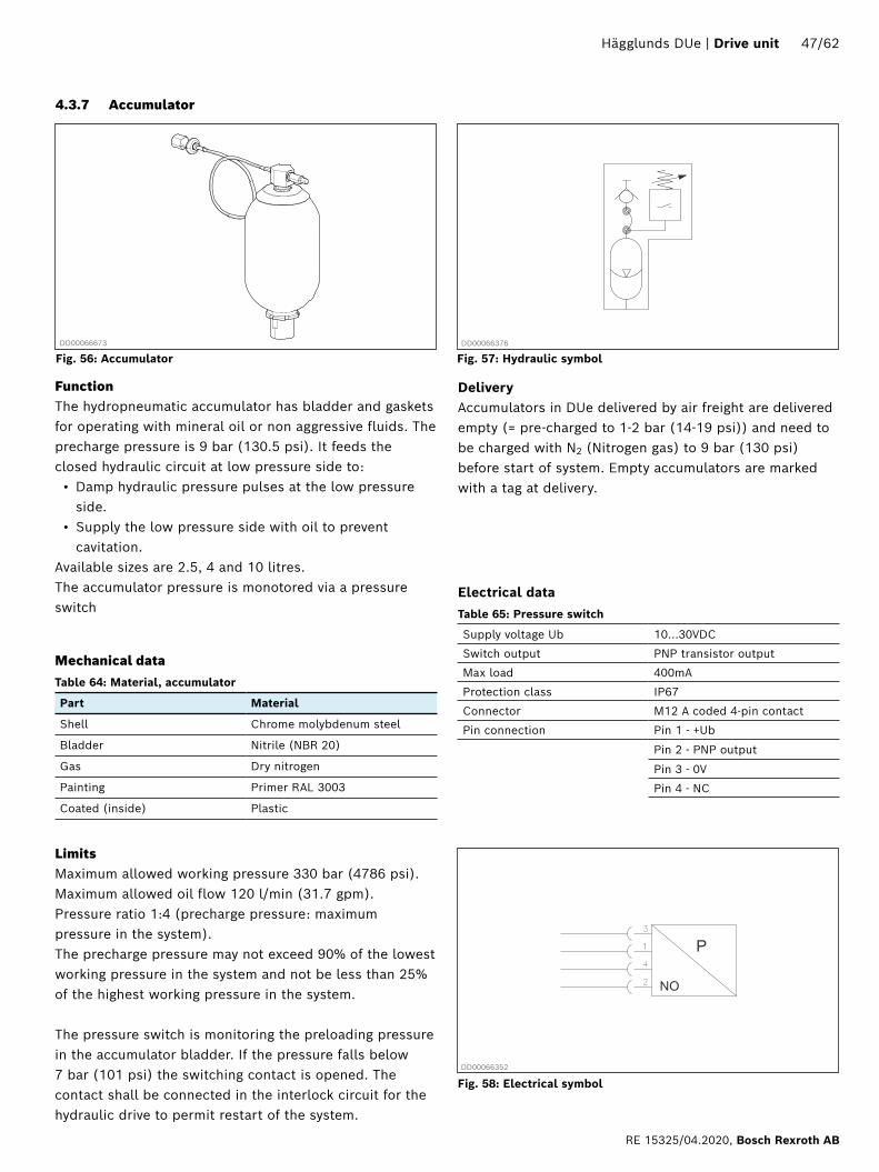
4.3.7 Accumulator
FunctionThe hydropneumatic accumulator has bladder and gaskets for operating with mineral oil or non aggressive fluids. The precharge pressure is 9 bar (130.5 psi). It feeds the closed hydraulic circuit at low pressure side to:• Damp hydraulic pressure pulses at the low pressure
side.• Supply the low pressure side with oil to prevent
cavitation.Available sizes are 2.5, 4 and 10 litres.The accumulator pressure is monotored via a pressure switch
Mechanical dataTable 64: Material, accumulator
Part Material
Shell Chrome molybdenum steel
Bladder Nitrile (NBR 20)
Gas Dry nitrogen
Painting Primer RAL 3003
Coated (inside) Plastic
LimitsMaximum allowed working pressure 330 bar (4786 psi).Maximum allowed oil flow 120 l/min (31.7 gpm).Pressure ratio 1:4 (precharge pressure: maximum pressure in the system).The precharge pressure may not exceed 90% of the lowest working pressure in the system and not be less than 25% of the highest working pressure in the system.
The pressure switch is monitoring the preloading pressure in the accumulator bladder. If the pressure falls below 7 bar (101 psi) the switching contact is opened. The contact shall be connected in the interlock circuit for the hydraulic drive to permit restart of the system.
Fig. 56: Accumulator Fig. 57: Hydraulic symbolDD00066376DD00066673
Fig. 58: Electrical symbolDD00066352
Electrical dataTable 65: Pressure switch
Supply voltage Ub 10...30VDC
Switch output PNP transistor output
Max load 400mA
Protection class IP67
Connector M12 A coded 4-pin contact
Pin connection Pin 1 - +Ub
Pin 2 - PNP output
Pin 3 - 0V
Pin 4 - NC
DeliveryAccumulators in DUe delivered by air freight are delivered empty (= pre-charged to 1-2 bar (14-19 psi)) and need to be charged with N2 (Nitrogen gas) to 9 bar (130 psi)before start of system. Empty accumulators are marked with a tag at delivery.
Hägglunds DUe | Drive unit 47/62
RE 15325/04.2020, Bosch Rexroth AB

4.3.8 Auxillary pumps
FunctionThe auxiliary pumps are used when external circuits are needed for flushing and/or brake functionalities.
The pump type used is an external gear pump.
Fig. 59: Auxillary pump
Fig. 60: Hydraulic symbol
ReferenceFor more information see the specific data sheets chapter 7 Required and additional documents
Table 66: Auxillary pumps
Pump size
Ordering code Max continuous pressure
Max peak pressure
cc bar psi bar psi
4 AZPF-12-004RCB20MB 250 3626 300 4351
11 AZPF-12-011RCB20MB 250 3626 300 4351
32 AZPG-22-032RCB07MB 250 3626 300 4351
56 AZPG-22-056RCB07MB 195 2828 250 3626
DD00109433
DD00109434
48/62 Drive unit | Hägglunds DUe
Bosch Rexroth AB, RE 15325/04.2020

FunctionThe pressure sensor gives information about the pressure level in different parts of the hydraulic system. The signal is used for information about system usage and/or used for control functions.
Electrical dataTable 67: Pressure sensor
Measuring range Work pressure 0…400bar
Low pressure 0...250bar
Supply voltage Ub 16...36VDC
Output 4…20mA
Max load (ohm) (Ub-8.5V)/20mA
Protection class IP65
Connector 4 pole M12
Pin connection Pin 1 - +Ub
Pin 2 - signal output
4.3.9 Pressure sensor
Fig. 61: Pressure sensor
DD00066344
Fig. 62: Hydraulic symbolDD00066597
Fig. 63: Electrical symbol
DD00068508
Bosch Bosch lkdhls lkhdl sch dkru vis siulösld dlsp skru vis siul
49/62 Drive unit | Hägglunds DUe
Bosch Rexroth AB, RE 15325/04.2020

4.3.10 Oil heater
DD00066312
Fig. 64: Oil heater
DD00066363
DD00066377
FunctionAt installation in ambient temperature below 0 °C (32 °F)a heater is needed in the oil tank to keep the oil temperature above a set level. The control system measures the temperature in the tank and gives an output to control an external relay to switch on/off power to the heater. The oil heater is an electrical block heater, with the heating coils in direct contact with the oil.
Fig. 65: Hydraulic symbol
Fig. 66: Electrical symbol
Mechanical dataTable 68: Oilheater
Tubular elements Stainless steel 1.4404
Head Brass 2”
Heater length 435 mm
Terminal box Silumin
Lid Carbonate plastic
Protection class IP54
Electrical dataTable 69: Oilheater
Power 670 W
Voltage 220-240 V
380-415 V
440-480 V
660-690 V
Fig. 67: Electrical connections
Electrical connectionsThe cable is connected on screw terminals inside the terminal box.
PE
L1
L2
L3
PE
L1
N
(415/480/690) VAC (240) VAC
DD00073645
Hägglunds DUe | Drive unit 50/62
RE 15325/04.2020, Bosch Rexroth AB

4.3.12 Electrical connection box
FunctionElectrical signals from sensors and valves in the drive unit are connected to the control system or junction box via distributed connection boxes. Connections from the boxes to the actuators are distributed via short connection cables with M12 contacts on the connection box side.
Electrical dataTable 71: Connection box
Material Housing PBT, Moulding PUR
Degree of protection IP67
Contact material CU alloy goldplated
Cable type PUR black (LiYY11Y-HF)
Cable area 0.5 mm² (Power 1 mm²)
Ambient temperature -25 °C ... 80 °C
Electrical connections 4 pin, Female M12 A-standard (IEC 610 76-2-101)
Number of connections 4 or 8
DD00066653
4.3.11 Drain temperature sensor
DD00066383
DD00066354
FunctionThe drain temp sensor measures the temperature in the drain line from the hydraulic motor or/and from the main pump. The signal is controlling the flushing circuit for cooling/heating of the hydraulic motor and the main pump.
Temp range 0…100°C
Supply voltage Ub 10…30VDC
Output 4…20mA
Max load (ohm) (Ub-7.5V/22mA
Protection class IP65
Connector DIN 43650 (Hirschman)
Pin connection Pin 1 - +Ub
Pin 2 - signal output
Electrical dataTable 70: Drain temperature sensor
DD00066598
Fig. 68: Drain temperature sensor
Fig. 69: Hydraulic symbol
Fig. 70: Electrical symbol
4.3.13 LED lightning
FunctionThe lightning inside the drive unit is of LED list type. One LED list per compartment is installed. The LED list is controlled via the Hägglunds Spider.
Electrical dataTable 72: LED lightning
Material Aluminum
Lenght 500 mm
Degree of protection IP68
Ambient temperature -40 °C ... 80 °C
Supply voltage 24VDC
Light output 260 Lumen
Power consumption 7,2W
Fig. 71: Electrical connection box
51/62 Drive unit | Hägglunds DUe
Bosch Rexroth AB, RE 15325/04.2020
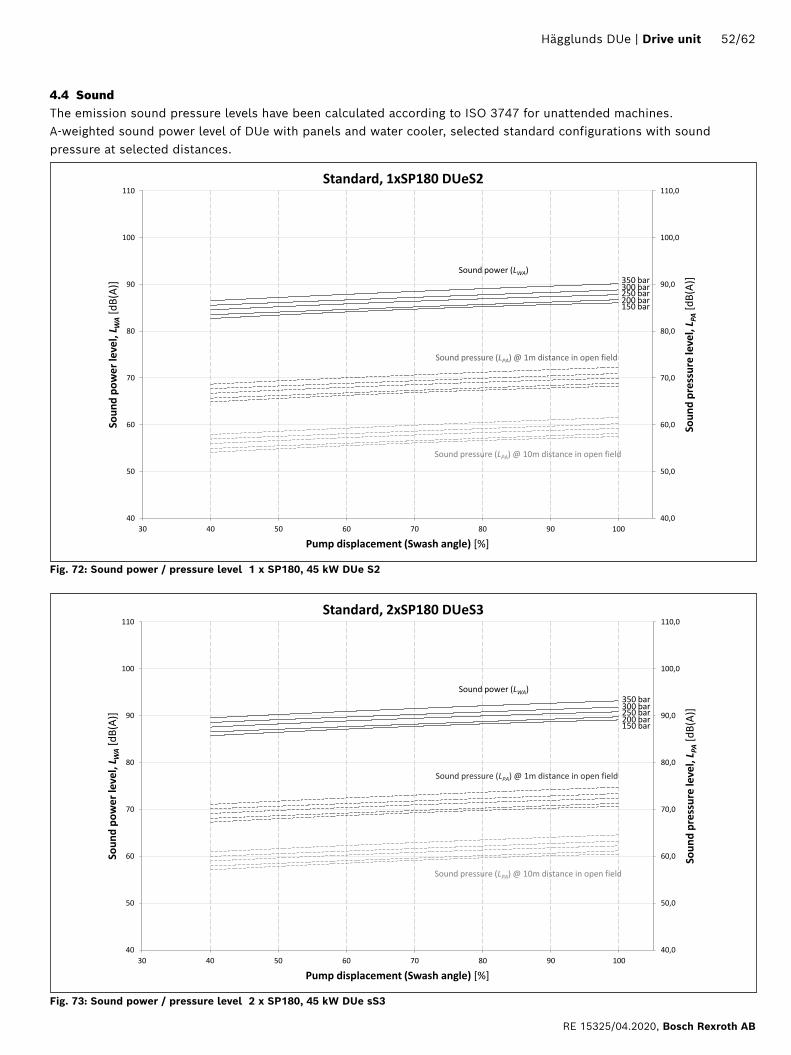
4.4 SoundThe emission sound pressure levels have been calculated according to ISO 3747 for unattended machines. A-weighted sound power level of DUe with panels and water cooler, selected standard configurations with sound pressure at selected distances.
40,0
50,0
60,0
70,0
80,0
90,0
100,0
110,0
40
50
60
70
80
90
100
110
30 40 50 60 70 80 90 100
Soun
d pr
essu
re le
vel, L P
A [dB
(A)]
Soun
d po
wer
leve
l, L W
A [dB
(A)]
Pump displacement (Swash angle) [%]
Standard, 1xSP180 DUeS2
350 bar 300 bar 250 bar 200 bar 150 bar
Sound power (LWA)
Sound pressure (LPA) @ 1m distance in open field
Sound pressure (LPA) @ 10m distance in open field
Fig. 72: Sound power / pressure level 1 x SP180, 45 kW DUe S2
40,0
50,0
60,0
70,0
80,0
90,0
100,0
110,0
40
50
60
70
80
90
100
110
30 40 50 60 70 80 90 100
Soun
d pr
essu
re le
vel, L P
A [dB
(A)]
Soun
d po
wer
leve
l, L W
A [dB
(A)]
Pump displacement (Swash angle) [%]
Standard, 2xSP180 DUeS3
350 bar 300 bar 250 bar 200 bar 150 bar
Sound power (LWA)
Sound pressure (LPA) @ 1m distance in open field
Sound pressure (LPA) @ 10m distance in open field
Fig. 73: Sound power / pressure level 2 x SP180, 45 kW DUe sS3
Hägglunds DUe | Drive unit 52/62
RE 15325/04.2020, Bosch Rexroth AB

40,0
50,0
60,0
70,0
80,0
90,0
100,0
110,0
40
50
60
70
80
90
100
110
30 40 50 60 70 80 90 100
Soun
d pr
essu
re le
vel, L P
A [dB
(A)]
Soun
d po
wer
leve
l, L W
A [dB
(A)]
Pump displacement (Swash angle) [%]
Standard, 2xSP355 DUeM2
350 bar 300 bar 250 bar 200 bar 150 bar
Sound power (LWA)
Sound pressure (LPA) @ 1m distance in open field
Sound pressure (LPA) @ 10m distance in open field
Fig. 74: Sound power / pressure level 2 x SP355, 60 kW DUe M2
40,0
50,0
60,0
70,0
80,0
90,0
100,0
110,0
40
50
60
70
80
90
100
110
30 40 50 60 70 80 90 100
Soun
d pr
essu
re le
vel, L P
A [dB
(A)]
Soun
d po
wer
leve
l, L W
A [dB
(A)]
Pump displacement (Swash angle) [%]
Standard, 4xSP355 DUeM3
350 bar 300 bar 250 bar 200 bar 150 bar
Sound power (LWA)
Sound pressure (LPA) @ 1m distance in open field
Sound pressure (LPA) @ 10m distance in open field
Fig. 75: Sound power / pressure level 4 x SP355, 60 kW DUe M3
53/62 Drive unit | Hägglunds DUe
Bosch Rexroth AB, RE 15325/04.2020

40,0
50,0
60,0
70,0
80,0
90,0
100,0
110,0
40
50
60
70
80
90
100
110
30 40 50 60 70 80 90 100
Soun
d pr
essu
re le
vel, L P
A [dB
(A)]
Soun
d po
wer
leve
l, L W
A [dB
(A)]
Pump displacement (Swash angle) [%]
Standard, 2xSP500 DUeL2
350 bar 300 bar 250 bar 200 bar 150 bar
Sound power (LWA)
Sound pressure (LPA) @ 1m distance in open field
Sound pressure (LPA) @ 10m distance in open field
Fig. 76: Sound power / pressure level 2 x SP500, 315 kW DUe L2
40,0
50,0
60,0
70,0
80,0
90,0
100,0
110,0
40
50
60
70
80
90
100
110
30 40 50 60 70 80 90 100
Soun
d pr
essu
re le
vel, L P
A [dB
(A)]
Soun
d po
wer
leve
l, L W
A [dB
(A)]
Pump displacement (Swash angle) [%]
Standard, 4xSP500 DUeL3
350 bar 300 bar 250 bar 200 bar 150 bar
Sound power (LWA)
Sound pressure (LPA) @ 1m distance in open field
Sound pressure (LPA) @ 10m distance in open field
Fig. 77: Sound power / pressure level 4 x SP500, 315 kW DUe L3
Hägglunds DUe | Drive unit 54/62
RE 15325/04.2020, Bosch Rexroth AB

4.5 Environment options
4.5.1 Flushing
Flushing is used either to cool or warm up the hydraulic motor and/or pump, depending on need due to the environ-mental conditions that the drive unit will be working at.Cold flushing is done by one of two different methods; • A separate pump that takes oil from the oil tank and
pumps it through one of the drain connections on the motor and/or pump and back to the tank.
• A check valve leads a part of the cooled oil from the oil cooler to the connecting ports on the motor and/or pump and back to the tank via drain line. This method can cause problems for air coolers due to pressure spikes, if the drive unit is supporting chock load applications.
When warm flushing is activated, oil from the tank is pumped by a separate flushing pump through a pressure relief valve and further to the motor and pump. When the oil passes the valve it gets warmed up.
4.5.2 Brake release system
The brake release system is an additional function where flow from either the charge pump or a separate pump is used to open the brake on the hydraulic motor depending on brake opening pressure level. The preset brake opening pressure level is 15, 60 or 200 bar (218, 870 or 2 901 psi) depending on brake type. The flow is controlled via a directional valve in the drive unit.
4.5.3 Low temperature
< 0°C (< 32°F)• It is recommended to equip the oil tank with a
heater.• It is recommended to equip the drive unit with an
auxiliary flushing circuit for warm flushing of pump(s) and hydraulic motor(s).
• An air-oil cooler has to be used, due to the freezing point of water.
< -20°C (< -4°F) • It is mandatory to equip the oil tank with a heater.• It is mandatory to equip the drive unit with an
auxiliary flushing circuit for warm flushing of pump(s) and hydraulic motor(s). The electric motor for the auxiliary circuit will be placed outside of the drive unit.
• All electric motors will be specified for temperatures < -20°C.
• Spider control unit will be equipped with heater.• The hydraulic compartment in the drive unit will be
sealed off, to avoid cold air from the electric motor to cool down the hydraulic area.
• The hydraulic compartments in the drive unit will be equipped with heaters.
< -30°C (< -22°F) All electric motors will be specified for temperatures < -30°C.
< -40°C (< -40°F) The drive unit has to be placed indoors.
4.5.4 High temperatureAmbient temperatures > 40 °C (104 °F) limit the permit-ted output power for the electric motor.For ambient temperatures > 40 °C (104 °F) it is recom-mended to use water-oil cooler.
55/62 Drive unit | Hägglunds DUe
Bosch Rexroth AB, RE 15325/04.2020

DD00066315
Rain cover
The drive unit can be equipped with rain protection if the hydraulic unit is placed outdoors exposed to rain. This is to prevent water to follow the air into the unit. An additional rain cover is protecting the top of Spider control unit.
4.5.5 Sound protection
4.5.6 Dust protection
If the unit is mounted on an inclined plane or if it is exposed to external influences such as wind or vibration, the unit can be anchored according to Fig. 81 .Anchoring support is not included in scope of supply.
DD00068721
Shield plate
DD00066404
Fig. 79: Shield plate
The drive unit can be equipped with dust protection if the unit is located in an environment with high dust content in the air. The unit is sealed off with shield plates between electiric motor and hydraulic compartment to prevent dirt contamination into the hydraulic part of the unit.
Shield plate
4.5.8 Anchoring possibility
Fig. 78: Sound trap
DD00066403
Sound trap
The drive unit can be equipped with extra sound protec-tion, which means that the weighted sound power level is in average 2dB(A) lower than than a drive unit with origi-nal panels. A drive unit with sound protection has sound trap fitted at the outlet for electric motor air and the outlet area for the pump high pressure hoses is covered with a thick insula-tion.
4.5.7 Rain protection
Fig. 80: Rain cover
Fig. 81: Anchored DUe
Rain cover
Hägglunds DUe | Drive unit 56/62
RE 15325/04.2020, Bosch Rexroth AB

4.5.9 Machine feetIf the unit needs to be isolated regarding vibrations or to compensate for uneven surfaces machine feet can be used. They have an adjustment range of 30-38 mm (1.18-1.50 inch).
4.5.10 Oil panThe bottom part of the DUe is designed to work as an oil pan for leakage oil. The oil can be removed from the pan via a drain tap on the front side. For oil pan size see 4.1.8
4.5.11 PaintingTwo different corrosivity categories regarding corrosion protection are available in accordance with SS-EN ISO 12944:• Corrosivity category - C3 Frame and external brackets: RAL 9005 BlackDoors, hoods and panels RAL 2002 Orange
• Corrosivity category - C5Frame and external brackets: RAL 9005 BlackDoors, hoods and panels: Stainless steel EN 1.4301
All external bolts, washers and nuts are A4 stainless steel.
4.5.12 Hazardous areasThe drive unit can be adapted to work in hazardous areas, ATEX Zone 1 or Zone 2. In order to comply with the requirements for certification particular components are needed and there may also be some limitations of functions from what a non-certified drive unit can handle.
57/62 Drive unit | Hägglunds DUe
Bosch Rexroth AB, RE 15325/04.2020

4.6 External pipe work GeneralThe drive unit should be placed close to the hydraulic motor in order to minimise piping if it is possible. See"4.1.2 Positioning the DUe", page 15
4.6.1 Pipe sizeThe pipe work between motor and the drive unit shall be dimensioned for at least four times the maximum pressure, the equipment may be re-adjusted to higher pressures in service.It is important that the lines between the main connections of the motor and drive unit are as short as possible. The total pressure drop in the main and return line must not exceed 5% of the normal working pressure.The pipe shall be sized to give the following approximate flow rates:Main lines < 5-7 m/sReturn lines < 3 m/sDrain & suction lines < 1 m/sIt is particularly important that the pressure in drain lines does not exceed the max. case pressure for motor/pump.
4.6.2 Material in hydraulic pipes Use a high-grade steel as per ISO 3304, DIN 2391/C or ASTMA 519 1010 for the hydraulic pipes.
4.6.3 Pipe couplings For pipes with:d ≤ 25 mm: SAE J514 (SAE-16)25 ≤ d ≤ 60 mm: SAE J518 (SAE-16)
4.6.4 Pipe clampsThe pipes shall be clamped with uniformly spaced clamps.The distance between the clamps depends on the type of clamps but it may not exceed the following values:15 ≤ d ≤ 38 mm max. 2 000 mmd ≥ 38 mm max. 3 000 mmIn addition, the pipes must be clamped immediately before and after a bend and immediately before transition to a hose.The pipe clamps shall be secured to a stable and non vibrating surface.The pipe clamps must be of a type permitting a certain amount of axial and radial motion in the clamped joint and have good vibration-absorbing property.
4.6.5 Welded couplings Welded couplings shall be avoided because of the high possibility of system contamination due to the welding process.
4.6.6 Hoses • Hoses shall always be used between piping and
hydraulic motor/pump.• Use flexible hoses to prevent imposing stress from
moving/vibrating equipment.• Connect hoses with attention to bending radius,
adequate slack for machine movement and select to hang without stressing the end fittings.
• Use hoses, if it is possible, to connect direct between unit and machine to ease fitting and reduce transmission of noise.
• The hoses must be short and have the smallest possible diameter in order to obtain a small compression volume. Maximum flow velocities listed under “Pipe size“ must however be taken into consideration.
4.7 Hydraulic fluidsThe Hägglunds DUe is primarily designed foroperation with hydraulic fluids according to ISO 11158 HM.Before the start of project planning, see data sheetRE 15414, Hydraulic fluid quick reference, for detailedinformation on hydraulic fluids and specific additionaldemands.
ISO 11158 ISO 15380 ISO 12922
Mineral oil based and mineral oil related hydraulic fluids
Environmentally acceptable hydraulic fluids
Fire resistanthydraulic fluids
Within these standards, not all fluid classes are allowed,some are recommended, and there are also additionaldemands (see data sheet RE 15414).
Hägglunds DUe | Drive unit 58/62
RE 15325/04.2020, Bosch Rexroth AB
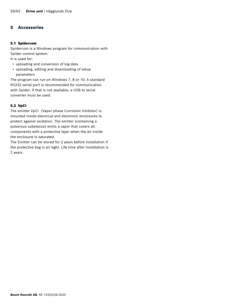
5 Accessories
5.1 SpidercomSpidercom is a Windows program for communication with Spider control system. It is used for: • uploading and conversion of log data • uploading, editing and downloading of setup
parameters The program can run on Windows 7, 8 or 10. A standard RS232 serial port is recommended for communication with Spider. If that is not available, a USB to serial converter must be used.
5.2 VpCIThe emitter VpCI (Vapor phase Corrosion Inhibitor) is mounted inside electrical and electronic enclosures to protect against oxidation. The emitter (containing a pulverous substance) emits a vapor that covers all components with a protective layer when the air inside the enclosure is saturated.The Emitter can be stored for 2 years before installation if the protective bag is air tight. Life time after installation is 2 years.
59/62 Drive unit | Hägglunds DUe
Bosch Rexroth AB, RE 15325/04.2020
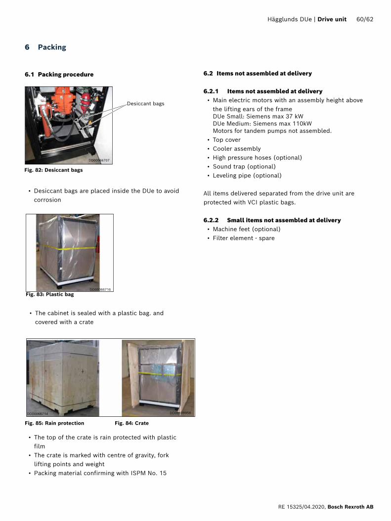
• The cabinet is sealed with a plastic bag. and covered with a crate
Desiccant bags
• Desiccant bags are placed inside the DUe to avoid corrosion
• The top of the crate is rain protected with plastic film
• The crate is marked with centre of gravity, fork lifting points and weight
• Packing material confirming with ISPM No. 15
Fig. 82: Desiccant bags
DD00066707
DD00066716
DD00108958DD00066714
Fig. 83: Plastic bag
Fig. 84: CrateFig. 85: Rain protection
6 Packing
6.1 Packing procedure 6.2 Items not assembled at delivery
6.2.1 Items not assembled at delivery• Main electric motors with an assembly height above
the lifting ears of the frame DUe Small: Siemens max 37 kW DUe Medium: Siemens max 110kW Motors for tandem pumps not assembled.
• Top cover• Cooler assembly • High pressure hoses (optional)• Sound trap (optional)• Leveling pipe (optional)
All items delivered separated from the drive unit are protected with VCI plastic bags.
6.2.2 Small items not assembled at delivery• Machine feet (optional)• Filter element - spare
Hägglunds DUe | Drive unit 60/62
RE 15325/04.2020, Bosch Rexroth AB
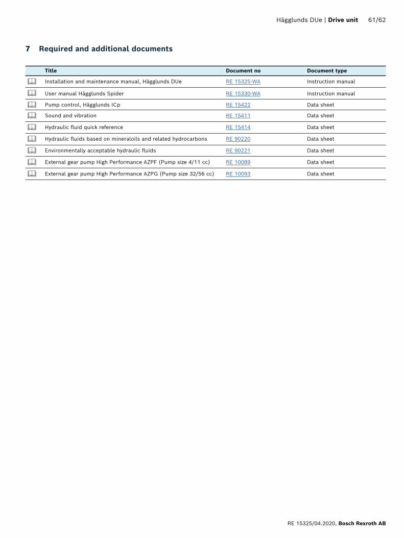
Title Document no Document type
Installation and maintenance manual, Hägglunds DUe RE 15325-WA Instruction manual
User manual Hägglunds Spider RE 15330-WA Instruction manual
Pump control, Hägglunds ICp RE 15422 Data sheet
Sound and vibration RE 15411 Data sheet
Hydraulic fluid quick reference RE 15414 Data sheet
Hydraulic fluids based on mineraloils and related hydrocarbons RE 90220 Data sheet
Environmentally acceptable hydraulic fluids RE 90221 Data sheet
External gear pump High Performance AZPF (Pump size 4/11 cc) RE 10089 Data sheet
External gear pump High Performance AZPG (Pump size 32/56 cc) RE 10093 Data sheet
7 Required and additional documents
Hägglunds DUe | Drive unit 61/62
RE 15325/04.2020, Bosch Rexroth AB

Bosch Rexroth AB895 80 Mellansel, SwedenTel: +46 (0) 660 870 00Fax: +46 (0) 660 871 [email protected]
The data specified above only serve to describe the product. As our products are constantly being further developed, no statements concerning a certain condition or suitability for a certain application can be derived from ourinformation. The information given does not release the user from the obligation of own judgment and verification. It must be remembered that our products are subject to a natural process of wear and aging
Bosch Rexroth AB,RE 15325/04.2020