hid light pocket guide
DESCRIPTION
HID Light MaintenanceTRANSCRIPT

Pocket Guide to
High Intensity Discharge Lamp Ballasts
Description of HID Lamp Types - 5Mercury Vapor - 5 Low Pressure Sodium - 5High Pressure Sodium - 6Metal Halide - 6Pulse Start Metal Halide - 7
General Ballast Description - 8
Ballast Circuitry - 9Lamp/Ballast Regulation Characteristics - 9
Ballast Circuits - 10Reactor - 10High Reactance Autotransformer - 11Constant Wattage Autotransformer (CWA) - 12Constant Wattage Isolated (CWI) - 13Regulated Lag - 14Electronic HID Ballasts - 15
Standards and Safety Agencies - 16ANSI – American National Standards Institute - 16UL – Underwriters Laboratories - 16
UL Bench Top Temperature Rise - 16CSA- Canadian Standards Association - 17
Ballast Design Applications - 18Magnetic Ballasts - 18
Core & Coil - 18Encapsulated Core & Coil - 19Indoor Enclosed - 19F-Can - 19Outdoor Weatherproof - 20Postline - 21
Electronic HID (eHID) - 21e-Vision® Low Frequency - 21DynaVision® - 21
TABLE OF CONTENTS

Ballast Components - 22Capacitors - 22
Dry Metalized Film - 22Oil Filled - 23
Ignitors (Starters) - 23
Application and Installation Information - 25Remote Mounting - 27Input Wiring - 27Bi-Level Operation - 27Warranty - 28
Troubleshooting - 28Safety - 28Instruments and Test Equipment - 29Troubleshooting Procedures - 29
Normal End of Lamp Life - 29Mercury and Metal Halide Lamps - 30High Pressure Sodium Lamps - 30Low Pressure Sodium Lamps - 30
Electronic Ballasts - 30
Troubleshooting Charts - 32Measuring Line Voltage - 36Measuring Open Circuit Voltage - 36Short Circuit Lamp Current Test - 40Capacitor Testing - 42Ballast Continuity Checks - 43
Continuity of Primary Coil - 43Continuity of Secondary Coil - 44
Ignitor Testing - 45Further Magnetic Ballast Checks - 46Electronic HID Ballasts - 47
Electronic Troubleshooting Flow Chart - 48
TABLE OF CONTENTS
4
High Intensity Discharge (HID) lighting sources are important for commercial, industrial and outdoor locations, such as high bay, parkinglot and street lighting. HID lighting sources include mercury vapor, lowpressure sodium (LPS), high pressure sodium (HPS), and metal halide(MH) ballast and lamp systems. Since the introduction of HID lighting,steady improvements in lamp and ballast technology have increasedefficiency and other performance characteristics of HID systems. Theimproved systems include pulse start (both quartz, ceramic arc tubesand ballasts), as well as electronic HID ballasts.
The purpose of this booklet is to provide technical information with a major focus on troubleshooting techniques for all HID systems including pulse start and electronic systems. The booklet is physicallydesigned to fit in your pocket or tool bag as a technical and troubleshooting ready reference.
For more detailed operational descriptions and specifications, refer tothe Philips Lighting Electronics Atlas (referred to in this document as"Atlas") or www.philips.com/advance.
Note: The information in this pocket guide is written based on our experience to date and believed to be reliable. It is a guide intended for use by persons having the necessary technical skills at their owndiscretion and risk. We do not guarantee favorable results or assumeany liability in connection with its use. This information is not intendedto conflict with existing code, ordinances and regulations. Existingcodes, ordinances and regulations should be observed at all times.

DESCRIPTION OF HID LAMP TYPES
5
There are four basic types of lamps considered as HID lightsources: mercury vapor, low pressure sodium, high pressuresodium and metal halide. All are arc discharge lamps. Light isproduced by an arc discharge between two electrodes at oppo-site ends of the arc tube within the lamp. Each HID lamp typehas its own characteristics that must be individually considered for any lighting application.
There are four key parameters:1. System efficiency (lumens per watt and ballast efficiency)2. Lamp life3. Lumen maintenance4. Color rendition and stability over the life of the lamp
Mercury VaporOften used in roadway lighting, mercury vaporlamps are the least efficient HID light source. To move users to more efficient technologies, a federal mandate now outlaws the manufactureand importing of mercury vapor ballasts into the United States for replacement or for use innew luminaries.
In the event of a mercury ballast failure, users should contacttheir sales representative to discuss lighting system replacementand upgrade options.
Low Pressure SodiumLow pressure sodium (LPS) lamps are grouped with HID lamps,but in fact do not have a compact, high intensity arc. They aremore like a fluorescent lamp with a long stretched-out arc. Theselamps are the most efficient light source with an efficacy of 100to 185 lumens per watt. LPS lamps have no color renderingindex as the color output is monochromatic yellow.

6
DESCRIPTION OF HID LAMP TYPES
Consequently, LPS has few viable applicationsbeyond street, parking lot and tunnel lighting. Low pressure sodium lamps range in size from18W to 180W and average 14,000 to 18,000 hour lifetimes. They have excellent lumen maintenance but the longest warm up times, from 7 to 15 minutes. LPS lamps feature theshortest re-strike time among HID sources—only 3 to 12 seconds.
High Pressure SodiumHigh pressure sodium lamps have an efficacy of 80 to 140 lumens per watt, a long lamp life of 20,000 to 24,000 hours, and the best lumenmaintenance of all HID sources. Wattages rangefrom 35W to 1000W and the warm-up time isfrom 2 to 4 minutes. Re-strike time is approxi-mately 1 minute. The biggest drawback of highpressure sodium is the yellowish color light output, but it is acceptable for use in manyindustrial and outdoor applications (e.g. roadway lighting). High pressure sodium andmetal halide lamps comprise the majority of HIDlighting applications.
Metal HalideMetal halide lamps have an efficacy of 60 to 110lumens per watt and have a warm-up time of 2 to5 minutes. They have a re-strike time of 10 to 20minutes. Lamp wattages range from 20W to1000W with lamp life of 6,000 to 20,000 hours.Wattages from 1500W to 2000W are specialtylamps used for sports lighting, and have lamplife ratings of only 3000 to 5000 hours. Theadvantage of metal halide lighting is its bright,

DESCRIPTION OF HID LAMP TYPES
7
crisp, white light output suitable for commercial, retail, andindustrial installations where light quality is important. However,lumen maintenance over the life of the lamps is less than optimalrelative to other HID sources.
The arc tube material for metal halide lamps was quartz until1995 when ceramic arc tube technology was developed.Ceramic arc tubes are now predominantly used in low wattage(20W to 150W) lamps, though new designs up to 400W haveemerged in recent years. Ceramic arc tubes provide improvedcolor consistency over lamp life. This technology is ideal forlamp applications requiring truer color as in fruit, vegetable,clothing and other accent lighting in retail displays.
Pulse Start Metal HalideIn the mid 1990s lamp manufacturers sought to improve stan-dard probe start metal halide lighting (175W to 1000W). They didso by changing the chemistry and fill pressure in the lamp arctube to increase lumen efficacy (lumens per watt). These lampimprovements required introduction of an ignitor or starter toprovide a high voltage starting pulse eliminating the internalstarting probe and its bi-metallic switch. Removal of the startingprobe and switch from the arc tube construction allowed anoptimized arc tube design and manufacturing process.
This technology improved the overall performance of metalhalide systems. Lumen output per watt consumed can increaseby 25%. Lumen maintenance is improved as much as 15%, lamplife is extended, warm-up time is reduced to two minutes andthere is some improvement in color rendition. Adding an ignitorreduced re-strike time to 4 to 5 minutes from the standard metalhalide lamp time of 10 to 20 minutes.

8
GENERAL BALLAST DESCRIPTION
GENERAL BALLAST DESCRIPTIONHID lamps provide light from an electric discharge or arc andhave a negative resistance characteristic that would cause themto draw excessive current leading to instant lamp destruction if operated directly from line voltage. The ballast is a power supply for arc discharge lamps. Its purpose in HID lighting is to provide the proper starting voltage to initiate and maintain the lamp arc and to sustain and control lamp current once thearc is established.
A ballast design incorporates basic circuitry to provide specific lamp/ballast operating characteristics. For some typesof lighting applications a particular ballast circuit has proven the most cost effective and is, therefore, the only circuit offered.Other applications may require an optimum ballast selectionfrom two or three available alternatives for that particular application. Final selection is based upon cost vs. performancerequirements.
As described in the previous section, HID lamps come in various types and wattage selections. Each lamp type andwattage requires specific starting and operating conditions todevelop rated light output and operate the lamp within allowable limits. Ballasts and lamps are designed to meet stan-dards for interchangeability between lamps and ballasts of thesame type and wattage. A lamp must be operated by the ballastdesigned for that lamp, as improper matching of lamp and bal-last may cause damage to the lamp or ballast or both. TheAmerican National Standards Institute (ANSI) provides specifi-cations to standardize lamp and ballast compatibility.
For many years all HID ballasts were magnetic ballasts operating at the power line frequency of 50 or 60 Hertz to pro-vide proper lamp operation. In the past few years electronic ballasts have been developed, primarily for metal

GENERAL BALLAST DESCRIPTION
9
halide lamps, using integrated circuits that monitor and control lamp operation. Electronic ballast circuits sense lampoperation characteristics and regulate lamp current to operatethe lamp at constant wattage, thus providing a more uniformlight output and color rendition throughout lamp life. They alsosense lamp end of life and other circuit conditions and shutdown the ballast when the lamp operating characteristics fail to meet operating specifications. These characteristics presentmore complicated troubleshooting conditions that will be discussed later.
BALLAST CIRCUITRYLamp/Ballast Regulation CharacteristicsOne of the most important characteristics of each particular ballast circuit is the degree to which it controls the lampwattage, and hence light output, with changes of input line voltage. Ballast circuit design dictates the lamp wattage regula-tion characteristics. As a rule, better lamp regulation requireslarger, more expensive ballasts. The following chart comparesthe relationship of the three basic types of ballast circuits as theinput voltage changes.
As an example, the CWA line indicates that at 90% of line volt-age, the ballast will operate the lamp at 90% of it nominalwattage. Similarly, at 110% of line voltage, the ballast will oper-ate the lamp at 110% of nominal wattage.
475
450
425
400
375
350
325
300
275
0 50 60 70 80 90 100 110 120 130 140 150 160 170
LAMP VOLTS
LAM
P W
ATTS
VOLT-WATT TRACES
INPUTVOLTAGE
TRAPEZOID BOUNDARY
NOMINAL LAMP VOLTAGE
NOMINAL
+10%
-10%
112
110
102 100
98
95
88
87 90 95 100 105 110 113
REACTOR (R)*
CWA**
CONSTANTWATTAGE(CW)***
PRIMARY VOLTAGE (%)
LAM
P W
ATTS
(%)
EHID

10
BALLAST CIRCUITRY
The voltage of a typical mercury or metal halide lamp remainsrelatively constant throughout its operational life — for this reason, the lamp wattage regulation of these ballasts can bedefined as a simple percent wattage change. High pressure sodi-um lamps, however, see significant arc tube voltage increasesduring their operational life; therefore, the high pressure sodiumlamp ballast must compensate for this changing lamp voltage(even with stable input voltages) to maintain constant lampwattage. Consequently, a simple percent wattage change is notan adequate definition for high pressure sodium lamp regula-tion. Instead, a trapezoid, established by the American NationalStandards Institute (ANSI), is defined, which restricts the opera-tion of the lamp to certain acceptable limits with respect to lampvoltage and resulting lamp wattage. The ballast is designed tooperate a high pressure sodium lamp throughout its life withinthe trapezoid for any input voltage within the rated input voltagerange of the ballast. The resultant value of the lamp's actualoperation wattage over the life of the lamp when shown on agraph follows a rising-then-falling path called a volt-watt trace.
BALLAST CIRCUITSReactor (R)– A single coil ballast can be used when the inputvoltage to a fixture meets the starting and operating voltagerequirements of an HID lamp. In this situation, the reactor ballastperforms only the current-limiting function since the voltagenecessary to initiate the ignitor pulses, and start and sustain thelamp comes directly from the input voltage to the fixture.
The reactor ballast is electrically in series with the lamp. There is no capacitor involved with the operation of the lamp.Because of that, the lamp current crest factor is desirably low, inthe 1.4 to 1.5 range.

BALLAST CIRCUITS
11
Without a capacitor, the reactor ballasts are inherently normalpower factor devices (50%). When desired to reduce the ballast input current required during lamp operation, a capacitor may be utilized across the input line to provide highpower factor (90%) operation, but the addition of the capacitorwill not affect how the ballast operates the lamp.
Reactor ballasts with power factor correction capacitors, can limitthe number of fixtures that can be used on a circuit because theydraw substantially more current during lamp starting (warm-up)and/or open-circuit operation (burned-out or missing lamp), thanwhen the lamp is operating normally.
High Reactance Autotransformer (HX) - When the inputvoltage does not meet the starting and operating voltage require-ments of the HID lamp, a high reactance autotransformer ballastcan be used. In addition to limiting the current to the lamp, an HXballast transforms the input voltage to the lamp’s required level.Two coils, called the primary and secondary, are employed withinthe ballast. The operating characteristics, such as lamp wattageregulation are similar to the reactor.
LAMP
CAP LAMP
LINE V
Typical ReactorCircuit withOptionalCapacitor

12
BALLAST CIRCUITS
The high reactance autotransformer ballast is also inherently anormal power factor (50%) ballast but can be corrected to a high power factor (90%) with the addition of a capacitor acrossthe primary coil. As with the reactor ballast, the addition of thiscapacitor does not affect the lamp’s operation.
Both reactor and high reactance ballasts provide the samedegree of lamp wattage regulation. For example, a simple 5% change in line voltage results in a 10-12% change in lampoperating wattage. However, this fair degree of lamp regulation is acceptable for many applications.
Typical HighReactanceAutotransformerCircuit withoutCapacitor
Constant Wattage Autotransformer (CWA), alsoreferred to as a “Peak Lead Autotransformer” – To correct the higher input current associated with reactor andhigh reactance ballasts, and to provide a greater level of lampwattage regulation, the 2-coil CWA ballast was developed. It isthe most commonly used ballast circuit for medium and highwattage (175W – 2000W) applications and typically representsthe best compromise between cost and performance. The CWAis a high power factor ballast utilizing a capacitor in series withthe lamp rather than across the input. The capacitor works withthe core-and-coil to set and regulate the lamp current to the pre-scribed level.

BALLAST CIRCUITS
13
The CWA ballast provides greatly improved lamp wattage regulation over reactor and high reactance circuits. A ± 10% linevoltage variation will result in a ± 10% change in lamp wattagefor metal halide. The metal halide and high pressure sodium ballasts also incorporate wave shaping of the open circuit voltageto provide a higher peak voltage than a normal sine wave. Thispeak voltage (along with a high voltage ignition pulse when anignitor is used) starts the lamp and contributes to the lamp cur-rent crest factor (typically 1.60 -1.65).
With the CWA ballast, input current during lamp starting or opencircuit conditions does not exceed the input current when thelamp is normally operating. CWA ballasts are engineered to tol-erate 25-30% drops in line voltage before the lamp extinguishes(lamp dropout), thus reducing accidental lamp outages.
Typical ConstantWattageAutotransformerCircuit
Constant Wattage Isolated (CWI) – The CWI ballast is atwo-coil ballast similar to the CWA ballast except that its secondary coil is electrically isolated from the primary coil. Thisisolated design permits the socket screw shell to be grounded forphase-to-phase input voltage applications such as 208, 240 and480 volt inputs. The use of the CWI ballast for these voltages is aCSA safety requirement in Canada.
LAMP
LAMP
LINE V
COM COM
LINE V
LINE V
LINE V
CAPCAP

14
BALLAST CIRCUITS
Typical ConstantWattage IsolatedCircuit
Regulated Lag (REG-LAG), also referred to as“Magnetic Regulator” or “MAG-REG” – This three-coilballast circuit consists of a reactor ballast with a two-coil voltage regulator circuit all assembled on one core. The primary coil works with the tertiary coil and its capacitor to reg-ulate the current through the lamp coil, and hence, the lamp.The lamp current crest factor is typically 1.5, similar to that ofsingle-coil reactor ballast.
The lamp coil portion of the ballast is essentially isolated fromline voltage variations and deviations from nominal. This circuit provides the best lamp wattage regulation for magneticballasts, (a ± 10% change in input voltage yields only a ± 4%change in lamp wattage) but carries an increase in ballast size,ballast losses and cost.
TypicalRegulated LagCircuit
LAMP 1
CAP
LAMP
COM
LINE V
LINE V
LINE V
IGNITORX1X3
X2
LINE V
CAP
CAP
LAMP 2
LAMP 1
LAMP
LINE V
COM
LINE V
LINE V
CAPCAP
LAMP 2

BALLAST CIRCUITS
15
Electronic HID (eHID) BallastsThere are two basic designs for electronic HID ballasts; lowfrequency square wave (typically used for low-wattage lampsor with ceramic arc tube lamps in the 250W-400W range) andhigh frequency (for medium wattage lamps in the 250W to400W range). Both make use of integrated circuit technologyto provide closer regulation and control of lamp operation overa variety of input voltage and lamp aging conditions. The inte-grated circuits in both types of ballasts continuously monitorinput line voltage and lamp conditions and regulate lamppower to the rated wattage. If any power line or lamp circuitcondition exists that will cause the lamp or ballast to operatebeyond their specified limits the ballast shuts down (removespower from the lamp) to prevent improper operation.Electronic HID ballasts improve lamp life, lamp lumen mainte-nance, and system efficiency.
Integrated circuit control allows most electronic ballasts to oper-ate at multiple input line voltages and, in some cases, operatemore than one lamp wattage. The lamps are operated with con-stant lamp power that provides better light output regulation andmore consistent light color over the life of the lamp. Some elec-tronic HID ballasts also offer a continuous dimming functionthat will dim the lamp to 50% (minimum) lamp power using 0-10V (DC) dimming control voltage.
All functions required to correct power factor, line current harmonics, and to start and control lamp operation are inherent in the ballast. The lamp socket must be pulse rated(dependant on lamp type) because there is an ignition pulsesupplied to start the lamp.

16
STANDARDS AND SAFETY AGENCIES
STANDARDS AND SAFETY AGENCIESANSI – American National Standards Institute is a non-profit organization that generates voluntary product performance standards for many U.S. industries, including ballasts and lamps. ANSI lighting committees consist of mem-bers from ballast, lamp, and fixture designers and manufacturersthat meet periodically to provide consistent product performancerequirements. There are specific performance standards for eachlamp and ballast type.
UL – Underwriters Laboratories, Inc sets safety standards for building materials, electrical appliances and otherproducts, including ballasts and lighting fixtures. These stan-dards include prescribed requirements for insulation systems and maximum operating temperatures.
UL provides, through testing, two different approvals for ballasts, UL Listed and UL-Recognized. UL Listing indicates the ballast is approved as a stand-alone unit and nofurther safety testing of the ballast is required by the fixturemanufacturer. UL Listed ballasts are manufactured in an enclo-sure and the fixture manufacturer cannot change the internalcomponents. UL-Recognized is a limited approval given to indi-vidual components that are not enclosed when manufactured.The fixture manufacturer must obtain UL Listing for the fixtureenclosure that includes meeting temperature and insulationrequirements of the ballast and associated components. Theballast manufacturer provides temperature and insulation ratinginformation to the fixture manufacturer.
UL Bench Top Temperature Rise information is providedas a letter code for each core and coil ballast in the Atlas and onthe ballast label to facilitate UL inspection. The temperature risecode is shown on the label as 1029X, where 1029 is the ULstandard for HID ballasts and the X is the temperature letter

code. This temperature information should be used when ballastreplacements are required. A ballast with a lower or equal letterrating may be used as a replacement without affecting UL listingof the fixture. For example, if a fixture is UL listed for 1029Cthen, automatically, electrically equivalent ballasts with an A, B,or C temperature classification are acceptable for use within thatsame fixture.
A table is shown below giving the letter code and the temperature range.
UL approves maximum temperature ratings for insulation
systems that include the wire insulation and the ballast impreg-nation material. Philips Advance ballasts may have one or bothof two temperature ratings, Class H - 180°C or Class N - 200°C. These temperature ratings are maximum operationtemperatures. However, greater ballast reliability will berealized when the operating temperatures are lower than themaximum. The rule of thumb is: Ballast life can double for each10°C decrease in operating temperature.
CSA – Canadian Standards Association is the Canadianequivalent to UL. They generate performance and safety stan-dards for many Canadian industries. When a product has theCSA symbol on the label, it has been investigated and approvedfor use in Canada.
STANDARDS AND SAFETY AGENCIES
17
UL Bench Top RiseLetter Code
Temperature Range forClass H (180°C) Ballasts
Temperature Range forClass N (200°C) Ballasts
A less than 75°C less than 95°CB 75°C < 80°C 95°C < 100°CC 80°C < 85°C 100°C < 105°CD 90°C < 95°C 105°C < 110°CE 90°C < 95°C 110°C < 115°CF 95°C < 100°C 115°C < 120°C
etc. etc. etc.

18
BALLAST DESIGN APPLICATIONS
BALLAST DESIGN APPLICATIONS
Magnetic BallastsPhilips Advance HID ballasts are available in a variety of shapesand sizes for the most popular lighting applications. Six basicdesigns are available for magnetic ballasts.
Core & Coil (71A)The electromagnetic or “magnetic” ballast is an inductor consisting of one, two or three copper or aluminum coilsassembled on a core (or “stack”) of electrical-grade steel laminations – commonly referred to as a core-and-coil ballast(71A). This assembly transforms electrical power into a form appropriate to start and operate HID lamps. Ballasts for highpressure sodium and pulse start metal halide lamps also includean ignitor to start the lamp. The third major component is thecapacitor, which improves the power factor, subsequently reduc-ing line current draw, and in some ballasts circuits works withthe core-and-coil to set the lamp operating wattage.
Typically, all three components – the basic open core-and-coil,capacitor, and ignitor – are assembled directly into the lightingfixture by the lighting luminaire manufacturer. However, someballast core-and-coil assemblies are encased in a container tomeet specific needs. Core-and-coil ballasts are UL-Recognized.A description of the various encased ballasts follows.

BALLAST DESIGN APPLICATIONS
19
Encapsulated Core & Coil (73B) In this configuration the capacitor is mounted separately in theluminaire, as is the ignitor (where required). Typical applicationsare installations requiring minimum ballast noise, includingindoor installations such asoffices, schools and retailstores. For a given applicationthe encapsulated core & coilballast also operates about10°C cooler than the opencore & coil. Encapsulatedcore & coil ballasts are UL-Recognized.
Indoor Enclosed (78E)Indoor enclosed ballasts are UL-Listed for indoor use where theballast must be mounted remotely from the luminaire. Theseballasts are typically used in applications where the luminairemay be mounted in an area withvery high ambient temperatures.The ballast can be mountedremotely in a cooler location. Thecase contains the core-and-coilballast potted in a heat-dissipatingresin (Class H, 180°C max.) withinthe ballast compartment. Thecapacitor and ignitor (where used)are also included within the case.
F-Can (72C)F-Can ballasts are also UL-Listed for indoor use and are com-monly used with recessed downlighting fixtures to minimizeinherent ballast noise. F-Can ballasts are stand-alone productsencased and potted in larger fluorescent ballast-style housings.F-Can ballasts utilize Class A (105°C rating, 90°C maximum

20
BALLAST DESIGN APPLICATIONS
case temperature) insulating materials for normal indoor ambi-ents. Each ballast unit has an integral auto-reset thermal protec-tor, which disconnects the ballast from the power line in theevent of overheating to protect the ballast and prevent meltingand dripping of the asphalt fill. All ballasts include the capacitorwithin the housing. All models for high pressure sodium, andmedium and low wattage pulse start metal halide ballasts alsoinclude the ignitor within the housing.
Outdoor Weatherproof (79W)Outdoor weatherproof ballasts are designed for remote mount-ing outdoors under all weather conditions. They may also beplaced inside a pole base, but care must be taken to avoid areasprone to flood situations as weatherproof ballasts are not water-submersible. They must also be mounted base (nipple) down,with a drip loop for the wiring, when exposed to weather. A core& coil, with capacitor and ignitor(where required) are firmly mountedto the heat-sink base. This assemblyis then protected with an aluminumcover, gasketed and bolted to thebase. The most common applicationsare billboard, road sign lighting andsome outdoor sports facilities, suchas tennis courts. Outdoor weather-proof ballasts are UL Listed for opera-tion remote from the lighting fixture.

BALLAST DESIGN APPLICATIONS
21
Postline (74P)Lantern-type, post-top fixtures mounted on slender poles oftenrequire ballasts which fit in the poles. Postline ballasts include aspecial, elongated core & coil encased and pot-ted in high temperature resin (Class H, 180°Cmax.) in cylindrical housings of a diameter toaccommodate being placed within 3” or 4”diameter poles. The capacitor and ignitor (whererequired) are included within the housing.Postline ballasts are often supplied with hangerchain for mounting and a spring clip designed topress the ballast against the pole wall for addedheat sinking. Postline ballast are UL-Recognized.
Electronic HID (eHID)Note: eHID ballast development is a rapidly expanding segmentof the lighting industry. Consult Philips Lighting Electronicsoften for the latest specifications on currently available ballasts.
e-Vision Through color consistency, versa-tility, and cost-efficiency, e-Visionballasts for 20-315W eHIDlamps offer retail, institutional,commercial and outdoor users an optimal choice for low wattage applications.
DynaVisionOffering superior lumen mainte-nance capabilities, our DynaVisionelectronic HID ballasts for 320-400watt pulse-start metal halide lampsrepresent a powerful and cost-effective lighting option for retail,manufacturing, and institutional users.

22
BALLAST COMPONENTS
The Philips Advance DynaVision electronic ballasts aredesigned for operation of 320W, 350W and 400W quartz arctube, pulse start metal halide lamps, and provide dramaticlumen maintenance improvement over magnetically ballastedprobe start MH and pulse start MH systems.
BALLAST COMPONENTSCapacitorsAll high power factor (HPF) Reactor (R) and High Reactance(HX) ballasts, as well as all Constant Wattage Autotransformer(CWA), Constant Wattage Isolated (CWI) and Regulated Lag ballasts require a capacitor. With core and coil and encapsulated core-and-coil units the capacitor is a separatecomponent and must be properly connected electrically. The capacitor for outdoor weatherproof, indoor enclosed, F-can and postline types are already properly connected withinthe assembly.
Two types of capacitors are currently in use: dry metalized filmand oil-filled. Present capacitor technology has allowed all but afew capacitor applications to be dry film. Oil-filled capacitors areused only when dry film technology cannot satisfy capacitorvoltage requirements.
Dry Metalized Film Capacitors are available to fill almostall needs for HID ballast applications.Philips Advance dry film capacitors typi-cally require only half the space used byoil filled capacitor and do not require additional spacing for safety. The compact, light weight, cylindrical non-conductive case and two insulatedwires or terminals reduce the requiredmounting space as compared with

BALLAST COMPONENTS
23
oil-filled capacitors. The discharge resistors (when required) areinstalled within the capacitor case. Dry film capacitors are UL-Recognized and contain no PCB material.
The maximum allowed dry film capacitor case temperature is 105°C.
Oil-Filled capacitors supplied today contain non-PCB oil andare a UL-Recognized component. Oil-filled capacitors are onlysupplied with ballasts where the capacitor operating voltage cannot be satisfied by dry film capacitors. Whenrequired, the capacitor discharge resistor is connected acrossthe capacitor terminals.
Additional precautions must be takenwhen an oil filled capacitor is installed.Underwriters Laboratories, Inc. (UL)requires clearance of at least 3/8 inchabove the terminals to allow for expansion of the capacitor in the eventof failure.
The maximum case temperature for oil-filled capacitors is 90°C.
Ignitors (Starters)An ignitor is an electronic component that must be included inthe circuitry of all high pressure sodium, low wattage metalhalide (35W to 150W) and pulse start metal halide (175W to 1000W) lighting systems. The ignitor provides a pulseof at least 2500 volts peak to initiate the lamp arc. It is important to note that ignitors are specifically designedto operate properly with specific ballasts and cannotbe interchanged with other ignitors or different brandsof ignitors and ballasts. The ignitor should always bemounted near the ballast but not on the ballast.

24
BALLAST COMPONENTS
When the lighting system is energized, theignitor provides therequired high voltagepulse until the lamp arcis established and auto-matically stops pulsingonce the lamp has started. It also furnishes the pulse continu-ously when the lamp has failed or the socket is empty.
All lighting systems requiring ignitors must be supplied with special pulse rated lamp sockets to prevent voltage breakdown and arcing from the highvoltage ignitor pulse. If a lighting system is being convertedto a lamp and ballast requiring an ignitor from a system without an ignitor, the lamp socked must be changed to a pulserated lamp socket or the lamp may not start reliably.
Ballasts that include an ignitor to start the HID lamp are limited in the distance they may be mounted remotely from thelamp because the ignitor pulse attenuates as the wire lengthbetween the ballast and lamp increases. All Philips Advanceopen core and coil ballasts listed in the Atlas include a standardignitor that provides the proper electrical pulse to start lampswhen the ballast is mounted within the lighting fixture. For mostof these ballast/ignitor combinations, the typical maximum bal-last-to-lamp distance is listed in the Atlas as 2 feet. When thisdistance is exceeded the lamp may not start reliably and a longrange ignitor is required. The Atlas lists the proper long rangeignitor required for various high pressure sodium and metalhalide ballasts.
Philips Lighting Electronics has developed a long range ignitorcalled the Xtenza® for extended metal halide ballast to lamp dis-tances. Ballasts using this ignitor have an extended distance to

BALLAST COMPONENTS
25
lamp of 50 feet for reliable starting. The list of ballasts that canbe used with this extended range ignitor is in the ignitor sectionof the Atlas. There are also other long range ignitors for applica-tions not satisfied by the Xtenza®.
Some lighting applications require instant restarting of lampsafter a momentary loss of power to the fixtures. When an HIDlamp is hot after operation and power is removed and reapplied,it will not restart with a standard ignitor until the lamp sufficient-ly cools. When instant restrike of a hot lamp is required, a spe-cial ignitor is necessary that will provide a pulse with muchgreater peak voltage.
APPLICATION AND INSTALLATIONINFORMATION
Remote Mounting of ballasts is often done to reduce ballastaudible noise in sensitive applications and requires specialattention to ballast spacing and temperature considerations, distance to the lamp, and wire sizing.
Remote mounted ballasts are often mounted in groups in apanel box or room away from the lamp location. Ballasts dissipate heat that must be removed to prevent the ballasts from overheating.
Spacing between ballasts and the mounting surface must beconsidered when the ballasts are remote-mounted. Twelve inch-es between ballasts must be maintained. If multiple rows verti-cally are used, there should be at least 12 inches between rows.In addition to ballast and row spacing, the ballast must not bedirectly mounted to a non-metallic surface.

26
APPLICATION & INSTALLATION INFORMATION
In such cases F-Can ballasts must be spaced with mountingbrackets (available from Philips Lighting Electronics) to allowair flow under the ballast base.
Ballasts from the 72C, 78E and 79W series and some eHID bal-lasts are designed for stand-alone mounting, but maximum casetemperature ratings must be adhered to for proper ballast oper-ation and maximum ballast life. Take time to measure bal-last case temperatures of ballasts installed to verifythe ballasts are operating below the maximum casetemperature rating.
Ballast to lamp (BTL) distance and wire size are also importantmounting considerations. For ballasts using ignitors (high pres-sure sodium, low wattage metal halide and pulse start metalhalide), the BTL distance is restricted by the ignitor used. TheAtlas ballast specifications list the maximum allowable distance.The remote distance of ballasts with ignitors can often beextended by using long range ignitors, but there is a limit to thisdistance. Be sure to check the Atlas for maximum ignitor dis-tances. When an ignitor is used, increasing wire size does notnecessarily help to increase the allowable maximum distance. In fact, increased wire size can usually result in increased wirecapacitance which, can further attenuate the ignition pulse. If thewire from ballast to the lamp is routed through metal conduit,the wire insulation rating may have to be increased to preventinsulation failure due to the ignitor pulse.
For ballasts without ignitors (mercury and probe start metalhalide) the ballast to lamp distance is determined by wire sizewith the prevailed concern being voltage drop. In the Atlas HIDsection there is a wire size table. This table lists the wire size by distance to the lamp to keep voltage drop to the lamp below1%. Wire used must have a voltage rating above the open circuit voltage of the ballast.

APPLICATION & INSTALLATION
27
Input Wiring to the BallastMany Philips Advance HID ballasts have multiple voltage inputtaps. These taps allow 120, 208, 240, 277, 347 or 480 volt input connections. For 120, 277 and 347 volt input a common ballast lead wire is provided to be connected to the neutral inputlead. However, for the 208, 240 or 480 volt inputs both supplyconductors have voltage referenced to ground. One lead is con-nected to the proper ballast voltage lead and the other is con-nected to the ballast common lead. This connection causes theshell of the lamp socket to have voltage referenced to ground.The ballast will operate the lamp properly with these connec-tions. The fixture can be grounded but the lamp shell cannot. Anisolated output ballast (CWI or regulated lag) must be used if thelamp socket shell must be grounded, as is required for someinstallations in Canada.
Bi-Level OperationBi-level or two level dimming provide a means of saving energywhen full light output from a fixture is not required. This isaccomplished by changing capacitor values in the output ofCWA ballast circuits using a control relay in the fixture.Generally, the lamp power level selections are 100% and 50%.Both high pressure sodium and metal halide ballasts may bedimmed using this method.
The required capacitor values for bi-level ballast operation arelisted in the HID section of the Atlas. The listed capacitor valuesare for 100% and 50% lamp power. Also the capacitor circuitarrangement, parallel or series, is listed. HID lamps should notbe operated at less than 50% lamp power per lamp manufactur-er specifications and must be started and operated until lamp ishot (15 minutes) at 100% power.

28
APPLICATION & INSTALLATION INFORMATION
Warranty of Philips Advance branded Ballasts and ComponentsAll Philips Lighting Electronics magnetic HID ballasts and com-ponents are warranted for 2 years from the date of manufacture.eHID ballasts are warranted for 3 years. The date of ballast manufacture is stamped on the product. Contact PhilipsLighting Electronics at 800-372-3331 and select option 2 (tech-nical support) for additional information.
TROUBLESHOOTINGSafetySafety measures should always be taken when troubleshootingHID systems. Most procedures will require that power beapplied when electrical measurements are made. Wearinggloves and eye protection is a good practice when doing electri-cal measurements on HID systems.
Connection in parallelSwitch open for reducedlight output
Switch closed for fulllight output
Connection in seriesSwitch open forreduced light output
Switch closed for full light output
TROUBLESHOOTING
29
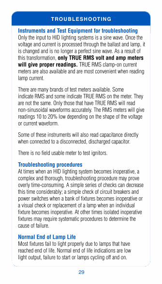
Instruments and Test Equipment for troubleshootingOnly the input to HID lighting systems is a sine wave. Once thevoltage and current is processed through the ballast and lamp, itis changed and is no longer a perfect sine wave. As a result ofthis transformation, only TRUE RMS volt and amp meterswill give proper readings. TRUE RMS clamp-on currentmeters are also available and are most convenient when readinglamp current.
There are many brands of test meters available. Some indicate RMS and some indicate TRUE RMS on the meter. Theyare not the same. Only those that have TRUE RMS will readnon-sinusoidal waveforms accurately. The RMS meters will givereadings 10 to 20% low depending on the shape of the voltageor current waveform.
Some of these instruments will also read capacitance directlywhen connected to a disconnected, discharged capacitor.
There is no field usable meter to test ignitors.
Troubleshooting proceduresAt times when an HID lighting system becomes inoperative, acomplex and thorough, troubleshooting procedure may proveoverly time-consuming. A simple series of checks can decreasethis time considerably; a simple check of circuit breakers andpower switches when a bank of fixtures becomes inoperative ora visual check or replacement of a lamp when an individual fixture becomes inoperative. At other times isolated inoperativefixtures may require systematic procedures to determine thecause of failure.
Normal End of Lamp LifeMost fixtures fail to light properly due to lamps that havereached end of life. Normal end of life indications are low light output, failure to start or lamps cycling off and on.

30
TROUBLESHOOTING
These problems can be eliminated by replacing the lamp. Sincemany HID fixtures are not easily serviced due to theirmounting height, the technician should take a replace-ment lamp when going up a ladder or on a lift.
Mercury and metal halide lamps at end of life are characterized by low light output and/or intermittent starting. It is possible for metal halide pulse start lamps to cycle off andon like high pressure sodium lamps at end of life. Visual indica-tions include blackening at the ends of the arc tube and elec-trode deterioration, but these are not conclusive. The sure testis to replace the lamp.
High pressure sodium lamps will tend to cycle at the end oflife. After start-up, they will cycle off and on as the aged lamprequires more voltage to stabilize and operate the arc than theballast is designed to provide.
Visual indications include general blackening at the ends of thearc tube. The lamp may also exhibit a brownish color (sodiumdeposit) on the outer glass envelope. The sure test is lampreplacement.
Low pressure sodium lamps retain their light output butstarting becomes intermittent and then impossible. Visual signsinclude some blackening of the ends of the arc tube. The suretest is lamp replacement.
Electronic BallastsLamps operated by electronic ballasts will not exhibitthe above metal halide symptoms at end of lamp life.Because electronic ballasts have sensing circuits to detect lampend of life, a ballast connected to an inoperative lamp will likelybe in a shut down mode or will not start. When servicing thefixture, always disconnect or shut off power to that fix-ture for safety. When the power is cycled off and then on, the

TROUBLESHOOTING
31
lamp may re-start and later go off and stay off. Visual indica-tions of the lamp may be the same. However, the true andsure test is to replace the lamp. After the lamp isreplaced the POWER TO THE BALLAST MUST BECYCLED OFF AND BACK ON FOR THE BALLAST TO RE-START THE LAMP.
NOTE: When the power is cycled off and back on via acircuit breaker or switch, other fixtures on the samecircuit will extinguish and not come back on until thelamps cool. The energized ballast will continue to produce high voltage starting pulses for a specifiedperiod, usually between 10 and 30 minutes dependingon the ballast model, allowing enough time for the hotlamp to cool.
It is assumed at this point in the troubleshooting procedure that the lamp has been replaced with aknown good lamp. If there is any doubt about a replacementlamp, it should be tested in an operational, good fixture.
Because troubleshooting can be time consuming, power to thefixture should be verified at the fixture. Photo cells, circuitbreakers and switches should all be checked. The following flowcharts are designed to minimize troubleshoot time and—if possible—eliminate taking the ballast housing apart.

32
TROUBLESHOOTING
TROUBLESHOOTING HID FIXTURES
Check Breaker,Fuse, Photocell
Lamp Starts(bad lamp)
Visually verify propercombination of lamp, ballast,
capacitor, ignitor andassociated wiring
Correct if not allcompatible
Inspect ballast capacitor, ignitorand lamp socket for physical
damage or signs of failure
Replace alldamagedcomponents
Measure open circuit voltage atlamp socket page 36
CAUTION!!If ignitor is presentit must be disabled before performing test!!
If in spec:Perform tests for
lighting componentsmove to STEP 3
If out of spec:continue testing
move on toSTEP 2
Replace Lamp withknown good lamp
Lamp will not start (STEP 1)

TROUBLESHOOTING
33
Measuring Line Voltage
Open Circuit VoltageMeasurement Out of Spec
Measure line voltage at ballastinput and verify conformance
with ballast label page 36
If not conforming:Electrical exist
outside of fixture
If conforming:Perform lighting component Tests
STEP 3
Recheck circuit wiring,fuses,breakers, photocells,switches, etc.
Lamp will not start (STEP 2)
34
TROUBLESHOOTING
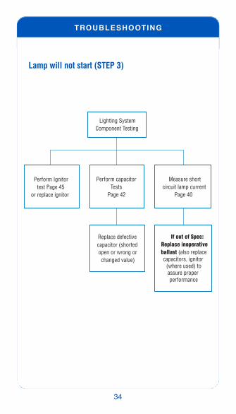
Lighting System
Perform Ignitortest Page 45
or replace ignitor
Perform capacitorTests
Page 42
Measure shortcircuit lamp current
Page 40
Replace defective capacitor (shorted open or wrong orchanged value)
If out of Spec:Replace inoperative ballast (also replace capacitors, ignitor
(where used) toassure proper performance
Component Testing
Lamp will not start (STEP 3)

TROUBLESHOOTING
35
Replace Lamp with anew or knownoperative lamp
Visually inspect andverify use of propercombination of lamp,ballast and capacitor
Replace anyapparently damagedballast, capacitor or
lamp socket
Check fixture supplyvoltage per ballast or
fixture label
If out of spec:Problem is outside
of the fixture
If in Spec:Go to STEP 3
Lamp Cycles
36
TROUBLESHOOTING
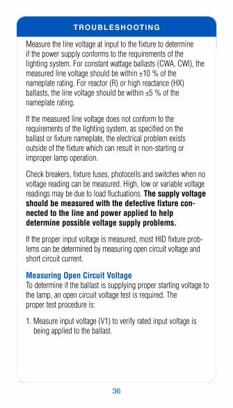
Measure the line voltage at input to the fixture to determine if the power supply conforms to the requirements of the lighting system. For constant wattage ballasts (CWA, CWI), themeasured line voltage should be within ±10 % of the nameplate rating. For reactor (R) or high reactance (HX) ballasts, the line voltage should be within ±5 % of the nameplate rating.
If the measured line voltage does not conform to the requirements of the lighting system, as specified on the ballast or fixture nameplate, the electrical problem exists outside of the fixture which can result in non-starting orimproper lamp operation.
Check breakers, fixture fuses, photocells and switches when novoltage reading can be measured. High, low or variable voltagereadings may be due to load fluctuations. The supply voltageshould be measured with the defective fixture con-nected to the line and power applied to help determine possible voltage supply problems.
If the proper input voltage is measured, most HID fixture prob-lems can be determined by measuring open circuit voltage andshort circuit current.
Measuring Open Circuit VoltageTo determine if the ballast is supplying proper starting voltage tothe lamp, an open circuit voltage test is required. The proper test procedure is:
1. Measure input voltage (V1) to verify rated input voltage isbeing applied to the ballast.

TROUBLESHOOTING
2. If the ballast has an ignitor [HPS, low wattage MH (35W to 150W) or pulse start MH], the ignitor must be disconnected or disabled with a capacitor (1000 pF or larger) across the voltmeter input to protect the meter fromthe high voltage ignitor pulse. Some ballasts have anintegral or built in ignitor. If you are not sure if anignitor is used put a capacitor across the meter forall open circuit voltage measurements.
3. With the lamp out of the socket and the voltage applied to theballast or the proper tap of the ballast with multiple voltageinputs, read the voltage (V2) between the lamp socket centerpin and shell. Some lamp socket shells are split. Make sureconnection is being made to the active part. The reading mustbe within test limits shown in table on page 38. Open circuitvoltage must be measured with a TRUE RMS voltmeter toprovide an accurate reading.
4. Constant wattage (CWA, CWI) ballasts have a capacitor inseries with the lamp. If the capacitor is open there will be noopen circuit voltage. Measure the voltage on both sides of thecapacitor. If the voltage exists on the ballast side but not onthe lamp side, change the capacitor and re-measure the open circuit voltage at the lampsocket. If there is still no voltage disconnect thelamp socket from the ballast and measure open circuit voltage again. Once a voltage is measuredtest the lamp socket for shorts with an Ohm-meteror replace the lamp socket. An ohm-meter test isnot conclusive as the test is at low voltage and thefailure may be due to the open-circuit voltage.
37

38
TROUBLESHOOTING
InputInput Output
LineLampSocket
OPEN-CIRCUIT VOLTAGE TEST LIMITS
OPEN-CIRCUIT VOLTAGE TEST M
ETAL
HAL
IDE
BALL
ASTS
LAMP RMSWattage ANSI Number Voltage*
50 H46 215-27075 H43 220-275100 H38 225-285125 H42 230-290175 H39 200-290250 H37 210-295400 H33 210-285
2-400 (Series) 2-H33 445-5451000 H36 385-465
35/39 M130 205-29050 M110 or M148 235-30070 M85 200-27070 M98 or M143 205-29070 M139 220-280100 M90 or M140 210-315150 M81 215-265150 M102 or M142 180-300 175 M57 or M107 275-355
175 P.S M137 or M152 250-340200 P.S. M136 215-330
250 M58 270-345250 M80 215-265
250 P.S. M138 or M153 245-330320 P.S. M132 or M154 240-310350 P.S. M131 240-315
400 M59 250-360400 P.S. M135 or M155 235-340400 P.S. M128 285-345
2-400 (ILO) 2-M59 300-360450 P.S. M144 235-340
MER
CURY
BAL
LAST
S

TROUBLESHOOTING
As an alternative, this test may be performed by screwing anadapter into the lamp socket for easy access. Some lamp sock-ets have a split shell and an adapter assures good electrical connection.
39
HIG
H P
RES
SUR
E SO
DIU
M B
ALLA
STS*
LOW
PRE
SSUR
ESO
DIU
M
BALL
ASTS
*Always disconnect the ignitor where equipped (typically used with metal halide<150W, pulse start metal halide, and high pressure sodium) before measuringthe output voltage of ballasts. High voltage starting pulses can damage com-monly used multi-meters
MET
AL H
ALID
EBA
LLAS
TSLAMP RMS
Wattage ANSI Number Voltage*750 P.S. M149 305-390875 P.S. M166 375-455
1000 M47 385-4851000 P.S. M141 370-475
1500 M48 405-5301650 M112 420-5102000 M134 405-495
35 S76 114-12650 S68 114-14070 S62 100-135100 S54 95-135150 S55 100-135150 S56 165-250200 S66 205-260250 S50 170-255310 S67 155-255400 S51 170-255430 SonAgro S145 180-220600 S106 200-265750 S111 200-2451000 S52 395-485
18 L69 280-33035 L70 430-53055 L71 430-53090 L72 430-575180 L74 610-760

TROUBLESHOOTING
40
Short Circuit Lamp Current TestDo not be concerned about momentarily shorting amagnetic HID ballast output. They will not instantlyburn up. An HID ballast is designed to limit current atthe specified value range.
To assure that the ballast is delivering the proper current underlamp starting conditions, a measurement may be taken by con-necting an ammeter between the lamp socket center pin and thesocket shell with rated voltage applied to the ballast. If available,a lamp socket adapter may be used as described in the opencircuit voltage test.
1. Energize ballast with proper rated input voltage.
2. Measure current with ammeter at A1 and A2 as shown in thediagram shown below.
3. Readings must be within test limits shown on page 41.
A clamp-on TRUE RMS ammeter may also be used to performthis test by placing an 18 gauge wire between the lamp andcommon leads of the ballast. When using a clamp-on ammeterfor this measurement, be certain the meter is not near the ballastmagnetic field or any steel object that may affect the reading.
The short circuit current test will also determine a defectivecapacitor in constant wattage circuits. A shorted capacitor will result in high short circuit current, while an open capacitor or low value capacitor will result in no or low shortcircuit current.

TROUBLESHOOTING
41
InputInput Output
LineLampSocketCommon
A
SHORT-CIRCUIT CURRENT TEST
SHORT-CIRCUIT LAMP CURRENT TEST LIMITS
MET
AL H
ALID
E BA
LLAS
TS
Secondary ShortCircuit Current Amps
MER
CURY
BAL
LAST
S
LAMPWattage ANSI Number
50 H46 .75-1.6075 H43 .85-1.50100 H38 1.15-2.00125 H42 1.60-2.60175 H39 1.90-3.30250 H37 2.60-5.00400 H33 4.55-7.10
2-400 (Series) 2-H33 4.4-5.401000 H36 5.50-6.70
25/39 M130 0.40-0.8050 M110 or M148 0.65-0.9570 M85 1.10-1.4070 M98 or M143 0.70-1.2570 M139 1.05-1.40100 M90 or M140 1.00-1.65150 M81 2.10-3.00150 M102 or M142 1.60-2.90175 M57 or M107 1.50-2.00
175 P.S. M137 or M152 1.60-1.95200 P.S. M136 1.80-2.70
250 M58 2.00-3.00250 M80 3.20-4.00
250 P.S. M138 or M153 2.35-3.05320 P.S. M132 or M154 2.90-3.70350 P.S. M131 3.25-4.40
400 M59 3.25-4.60400 P.S. M135 or M155 3.25-4.60400 P.S. M128 or M135 3.30-4.05
2-400 (ILO) 2-M59 3.90-4.80450 P.S. M144 3.85-5.10

42
TROUBLESHOOTING
Capacitor Testing and Ballast Performance1. Disconnect the capacitor from the circuit and discharge it by
shorting the terminals or wires together.
2. Check the capacitor with an ohmmeter set to the highestresistance scale• If the meter indicates a very low resistance then gradually
increases, the capacitor does not require replacement.• If the meter indicates a very high initial resistance that does
not change, it is open and should be replaced.
LAMPWattage ANSI Number
Secondary ShortCircuit Current Amps
HIG
H P
RES
SUR
E SO
DIU
M B
ALLA
STS*
LOW
PRE
SSUR
ESO
DIU
M
BALL
ASTS
MET
AL H
ALID
E BA
LLAS
TS
750 P.S. M149 4.90-6.00750 P.S. S111 9.20-11.70875 P.S. M166 4.45-5.40
1000 M47 4.70-6.401000 P.S. M141 4.60-6.90
1500 M48 7.00-10.501650 M112 7.80-9.602000 M134 9.80-12.00
35 S76 0.9-1.4050 S68 1.30-2.2070 S62 1.70-2.90100 S54 2.40-3.60150 S55 3.50-5.50150 S56 2.20-3.80200 S66 2.50-3.85250 S50 3.15-5.30310 S67 4.10-6.30400 S51 4.90-7.50430 SonAgro S145 6.00-7.40600 S106 6.85-10.50750 S111 9.20-11.701000 S52 6.40-7.80
18 L69 0.30-0.4035 L70 0.50-0.7055 L71 0.50-0.7090 L72 0.90-1.12180 L74 0.90-1.20

TROUBLESHOOTING
43
• If the meter indicates a very low resistance that does notincrease, the capacitor is shorted and should be replaced.
The ohmmeter method of testing capacitors will only determineopen or shorted capacitors. The capacitance value can be testedby many available portable TRUE RMS meters having that capa-bility, though a test using a dedicated capacitance meter is moreconclusive.
The capacitance value will affect lamp performance of Constant Wattage ballasts in ways that cannot be determined by the ohmmeter method. A capacitor may look good visually, but should be tested for capacitance value or replaced.
The capacitor in a reactor or high reactance ballast circuits willonly affect the ballast power factor and not ballast operation.Capacitor failure in these circuits will cause line supply currentchanges possibly causing circuit breakers to activate or fixturefuse failures.
Ballast Continuity ChecksContinuity of Primary Coil1. Disconnect the ballast from power source and discharge the
capacitor by shorting its terminals or wires together.
2. Check for continuity of ballast primary coil between the volt-age input leads as shown below.
Constant Wattage(CWA, CWI) TypeBallast Between Common andLine leads(CWA shown)
LAMP
LINE V
COMCOM
CAP
C

44
TROUBLESHOOTING
High Reactance(HX) Type BallastBetween Common and Capacitor leads
Reactor (R) TypeBallastBetween Line and Lamp leads
Continuity of Secondary Coil1. Disconnect the ballast from power source and discharge the
capacitor by shorting its terminals or wires together.
2. Check for continuity of ballast secondary coil between lampand common leads as shown below.
Constant Wattage(CWA, CWI) TypeBallasts not usingIgnitorsBetween Common and Capacitor leads(CWA shown)
High Reactance(HX) Type BallastBetween Common and Lamp leads
LAMP
LINE V
COMCOM
CAP
CCOMCAP
LAMP
LAMP
LINE V
COM
C
LAMP
LAMP
LINE V
COMCOM
CAPC
LAMP
LINE V
COMCOM
CCAP
LAMP
TROUBLESHOOTING
45
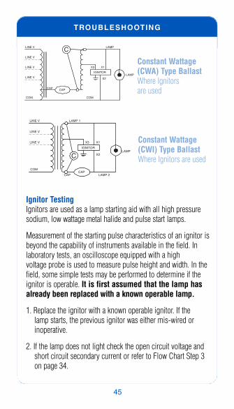
Constant Wattage(CWA) Type BallastWhere Ignitors are used
Constant Wattage(CWI) Type BallastWhere Ignitors are used
Ignitor TestingIgnitors are used as a lamp starting aid with all high pressuresodium, low wattage metal halide and pulse start lamps.
Measurement of the starting pulse characteristics of an ignitor isbeyond the capability of instruments available in the field. Inlaboratory tests, an oscilloscope equipped with a high voltage probe is used to measure pulse height and width. In thefield, some simple tests may be performed to determine if theignitor is operable. It is first assumed that the lamp hasalready been replaced with a known operable lamp.
1. Replace the ignitor with a known operable ignitor. If the lamp starts, the previous ignitor was either mis-wired orinoperative.
2. If the lamp does not light check the open circuit voltage andshort circuit secondary current or refer to Flow Chart Step 3on page 34.
LAMP
CAP
LAMP
COM COM
LINE V
LINE V
LINE V
IGNITOR
X1X3
X2
LINE V
CAP
C
LAMP 1
CAP
LAMP
COM
LINE V
LINE V
LINE V
IGNITOR
X1X3
X2
LAMP 2CAP
C

46
TROUBLESHOOTING
Further Magnetic Ballast ChecksProbable Causes of Inoperable Ballasts1. Normal ballast end-of-life failure
2. Operating incorrect lamps. Use of higher or lower wattagelamps than rated for the ballast may cause premature ballast end-of-life.
3. Overheating due to heat from the fixture or high ambient temperatures causing the ballast temperature to exceed thespecified temperature.
4. Voltage surge from lightening or power source malfunction.
5. Mis-wired, pinched or shorted wires.
6. Shorted or open capacitor.
7. Incorrect capacitor for the ballast.
8. Capacitor not connected to the ballast correctly.
Probable Causes of Shorted or Open Capacitors1. Normal capacitor end-of-life failure.
2. Overheated due to heat in the fixture or ambient temperature.
3. Capacitor mounted too close to ballast.
4. Incorrect voltage or capacitor value for ballast.
5. Mechanical damage such as over-tightened capacitor clamp.

TROUBLESHOOTING
47
Electronic HID BallastsElectronic HID ballasts present special troubleshooting challenges. The previously discussed procedures cannot beused to test electronic HID circuits. Electronic integrated circuitcontrol limits reliable testing that can be performed in the field.
An energized electronic HID ballast will attempt lamp ignition byproducing high voltage pulses for a specified time period, usu-ally between 10 and 30 minutes. Consult the ballast label forspecific times. Unlike magnetic HID ballasts, momentaryshorting either output lead of an electronic HID ballastto ground or each other will render the ballast perma-nently inoperable.
Verify that there is voltage at the input of the fixtureand the ballast before proceeding with the proceduresof the following Flow Chart.

48
TROUBLESHOOTING
Remove power from fixture (turn off switch
or circuit breaker or disconnect)
Replace Lampwith a new or known
operative lamp
Restore power tothe fixture
If lamp does not light:Check lamp socket andreplace if defective or
replace ballast
If the lamp lights:Defective lamp
Lamp will not start orcycles off after Lighting
NOTE: After lamp extinguishes or is replaced, fixture power must beremoved and restored to reset the electronics. Electronic ballasts aredesigned to shut down (remove power to the lamp) when irregularityoccurs in applied power or a lamp fails to operate within specifications.

NOTES
49

50
NOTES

NOTES
51

Philips Lighting Electronics10275 West Higgins RoadRosemont, Illinois 60018Tel: 800.322.2086 Fax 888.423.1882Customer Support/Technical Services: 800.372.3331
www.philips.com/advance
Form No. RT-8100-R02 12/09