high lead - superior sewing machine & supply llc gc20638, -d.pdf · purchasing dept copy high...
TRANSCRIPT

Purchasing Dept Copy
HIGH LEAD
GC20638/GC20638-D Compound Split Needle Bar Feed Lockstitch
Sewing Machine
Instruction Manual
Parts Catalog
SHANGHAI HUIGONG N0.3 SEWING MACHINE FACTORY
From the library of: Superior Sewing Machine & Supply LLC

From the library of: Superior Sewing Machine & Supply LLC

--- CONTENTS ---
Instruction Manual
1. PREPARATION FOR OPERATION ...................................................... 1
1) Latnp leads . . . . . . . . . . . . . . . . . . . . . . . . . . . . . . . . . . . . . . . . . . . . . . . . . . . . . . . . . . . . . . . . . . . . . . . . . . . 1
2) Connection of control box ............................................................... 1
3) Adjustment of needle bar stop position ..................................................... 2
2. CAUTIONS ON USE ................................................................... 2
1) Lubrication (1) ........................................................................ 2
2) Lubrication (2) ........................................................................ 2
3) Adjustment of oiling to rotating hook ...................................................... 2
4) Condition of oil lubrication .............................................................. 3
5) Cautions on operation ................................................................... 3
3. OPERATION ......................................................................... 3
1) How to attach needle ................................................................... 3
2) How to wind the lower thread ........................................................... 3
3) Selection of Thread .................................................................... 3
4) How to route the upper thread ............................................................ 4
5) Adjustment of stitch length and reverse sewing ............................................... 4
6) Settingbobbin ........................................................................ 4
7) Threading ofbobbin thread .............................................................. 5
8) Tension adjustment ofbobbin threads ...................................................... 5
9) Balance of thread tension ................................................................ 5
10) Needle thread tension .................................................................. 5
11) Adjustment of pressure of presser foot .................................................... 5
12) Timing between rotating hook motion and needle motion ...................................... 6
13) Adjustment of Feed dog height .......................................................... 6
14) Adjustment the needle stop position ....................................................... 6
15) Needle bar stop position (left & right) ...................................................... 7
16) Walking foot and presser foot vertical stroke adjustment ....................................... 7
1 7) Relationship between rotating hook motion and take-up lever motion ............................ 7
18) Relationship between hook motion and opener motion ......................................... 7
19) Relationship between needle motion and feed dog motion ...................................... 8
20) Safe clutch device .................................................................... 8
From the library of: Superior Sewing Machine & Supply LLC

21) Adjustnlent .......................................................................... 9
22) Installation of movable knife ............................................................ 9
23) Adjustnlent ofthread trimmer cam ...................................................... 10
24) Adjustnlent of threads tension release assembly ............................................. 11
25) Adjustnlent of scissoring pressure of movable knife and fixed knife ............................ 11
26) Sharpening of fixed knife .............................................................. 12
27) Adjustnlent for change ofneedle-to-needle distance ......................................... 12
Parts Catalog
A, ARM BED MECHANISM ............................................................. 13
B, THREAD TENSION REGULATOR MECHANISM ......................................... 16
C, ARM SHAFT*LOWER SHAFT MECHANISM ............................................ 20
0, PRESSER FOOT MECHANISM ......................................................... 22
E, NEEDLE BAR & TAKE-UP LEVER MECHANISM ........................................ 25
F, TOP FEED ROCK SHAFT MECHANISM ................................................ 28
G, LOWER SHAFT & FEED ROCK SHAFT MECHANISM .................................... 30
H, HOOK SADDLE MECHANISM ........................................................ 33
. L KNIFT MECHANISM ( 1) ............................................................... 35
J, KNIFT MECHANISM (2) ............................................................. 37
K, TOUCH BACK AND DETECTOR MECHANISM .......................................... 40
L OIL LUBRICATION MECHANISM ..................................................... 42
J, ACCESSORIES ...................................................................... 45
2
From the library of: Superior Sewing Machine & Supply LLC

1. PREPARATION FOR OPERATION
1) Lamp Leads
A. When installing the illuminating lamp (6V, 15-20W), The connecting wire is attached on the back of
the Control box. It should be removed and connected by removing the insulating tube from the wire
and stripping properly. The wire connections should be," then, insulated by wrapping insulating tape on
B.
the wires.
CAUTION: The power switch must be turned off before connecting the lamp.
When the illuminating lamp is not used, (b) lns~ating tape (a) Bare wire (2 to 3 turns wrapped)
the end of the lamp leads must be
insulated as (a ) or (b) as shown in the
figure on right side. If a short circuit
occurs failing to insulate, the transformer
in the control box will be possibly
burned out.
Lamp leads
lnsl.daHng tape (2 to 3 turns \\fapped)
Lamp leads
CAUTION: The illuminating lamp must not be connected with any heater, such as a foot
warmer and others, in parallel. Otherwise, the load capacity will be exceeded. It may cause
transformer winding burned out.
C. Rotary direction
It is possible to change the rotary direction of the motor by removing the rubber cap from the bottom
left side of the front cover on the control box, and push the internal direction selector switch. The
built-in lamp in the internal switch is off when the motor is
rotating counterclockwise as facing to the motor pulley, and on
when rotating clockwise. The rotary direction has been set to
counterclockwise as facing to the motor pulley, matching with the
machine prior to shipping.
2) Connection of control box(Fig.l)
The control box should be connected as shown to the right.
Note:
A. Be sure to turn the power switch off for safety before
connecting or disconnecting the connectors.
B. The combination of the machine heads with the motor control
panels are specified below. Use special care for the correct
combination when replacing the machine head or motor
control panel.
-I-
Black mark DOWN position
From the library of: Superior Sewing Machine & Supply LLC

3) Adjustment of needle bar stop position(Fig.2,Fig.3)
A. Adjust of "UP" position: When the pedal is kicked down by heel, the machine stops at "UP" position.
If the marks deviate larger than 3 mm, adjust as follows.
a. Disconnect the plug (12 pins) of cable from the
machine head.
b. Run the machine and stop at "UP" position.
c. While holding the pulley, insert the "adjusting
tool" in the hole "A", then remove the tool.
B. Adjust of "Down" position: When the pedal is
"Neutral" the machine stops at "Down" position. If
the marks deviate large than 5 mm, adjust as follows.
®
a. Disconnect the plug (12 pins) of cable from the machine head.
b. Run the machine and stop at "Down" position.
Adjueting toll
c. While holding the pulley, insert the "adjusting tool" in the hole "B", then remove the tool.
C. Confirm the stop operation, then set the plug (12 pings) coming from the machine head into the
receptacle.
2.CAUTIONS ON USE
-1) Lubrication (1 )(Fig.4)
Pour oil up to position "H" of the oil tank.
During operation, check the oil level periodically, and in cases
where the oil level is below position "L", replenish the oil
supply up to position "H".
Use white spindle oil.
2) Lubrication (2)(Fig.5)
When a new sewing machine is used for the first time, or sewing machine left out of use for a long time is
used again, replenish a suitable amount of oil to the portions indicated by arrow in the fig.
Note: Lubricate the Hook Base everyday.
3) Adjustment of
oiling to rotating
hook( Fig.6)
-2-
From the library of: Superior Sewing Machine & Supply LLC

4) Condition of oil lubrication (Fig.5):
While operating the machine, check the condition of oil lubrication through the oil check window.
5) Cautions on operation
A When the power is turned on or off, keep foot away from the pedal.
B It should be noted that the brake may not work when the power is interrupted or power failure occurs
during sewing machine operation.
C Since dust in the control box might cause malfunction or control troubles, be sure to keep the control
box cover close during operation.
D Do not apply a multimeter to the control circuit for checking; otherwise voltage of multimeter might
damage semiconductor components in the circuit.
3.0PERATION
1) How to attach needle (Fig. 7):
Note: Before attach needle, be sure to tum off the power.
Loosen the needle clamping screw; Hold the needles so that the
two needles side with the long grooved (faces each other), and
insert it as deeply as it will go into the needle clamping holes,
tighten screws.
2) How to wind the lower thread (Fig.S):
Strength of winding: Particularly in the case of nylon or
polyester thread, \Vind the bobbin loosely. 7
Uneven winding: If the bobbin is wound unevenly, slide the thread guide toward the less wound portion of
bobbin.
Winding amount: When the bobbin is wound excessively, loosen the adjusting screw. When the bobbin is
wound insufficiently, tighten the adjusting screw.
3) Selection of Thread (Fig.9):
\/Vindlng amount adjusting screw
Thread guid
I -· 3-
0
-Even winding With an amount 4/5 of fully capacny
Fig.8 Fig.9
From the library of: Superior Sewing Machine & Supply LLC

It is recommended to use "S" twist thread in the left needle (Viewed from front), and "Z" twist thread in the
right needle.
When discriminate use of needle thread 1s impossible, use "Z" twist thread in the needle. For bobbin thread,
"S" twist thread as well as "Z" twist thread can be used.
4) How to route the upper thread (Fig.lO, Fig.ll):
A Pass each upper thread through thread guide A
Note: when thin slippery thread (polyester thread for example) is used pass the thread through
thread guide Bas show in Fig.lO
B With the take-up lever located at the upper most position, pass each thread in the order in Fig.ll.
Note: Pressing the upper thread lt:t~sening button, the upper thread can be pulled out easily.
A 8 A 8 Needle thread tension releasing button
Lead the Lead the thread thread leftward rightward
5) Adjustment of stitch length and reverse sewing (Fig.12):
A Rotate the stitch length adjusting dial to change the stitch length
B Pressing the stitch length adjusting lever for reverse stitching.
6) Setting bobbin (Fig.13):
-4-
Fig.ll
From the library of: Superior Sewing Machine & Supply LLC

Leading the lower thread and install the bobbin
Pull out thread from side A, then install the bobbin case, Threading following CD-®; Put the bc,obin case
to rotating hook, then replace hook shaft; Press the bobbin bar, leading the lower thread over bedplate.
7) Threading of bobbin threads (Fig.14)
While holding the two needle Threads by left hand, rotate the hand-wheel one turn by right hand. By
pulling up the needle threads, as shown in the figure, the bobbin threads will be lifted. Each combination of
bobbin thread and needle thread should be aligned and led backward.
8) Tension adjustment of bobbin threads (Fig.15)
9) Balance of thread tension (Fig.16)
10) Needle thread tension (Fig.17)
Needle thread tension should be adjusted in reference to
bobbin thread tension. To adjust needle thread tension, tum
each tension adjusting nut. Needle thread tension can be
also adjusted for special fabric and thread by changing
intensity and movable range of slack thread adjusting spring.
11) Adjustment of pressure of presser foot (Fig.18):
Tension adjusting screw
AQ/"~33~ Balance tension
BX ~~~I~ E:= Ti;h't needle or loose
bobbin tension
cx.<~----1 bobbin tension I Fig.l6
~---
1~~-r~
}(-~· ! (
A Pressure should be adjusted according to the material to be sewn.
-5-From the library of: Superior Sewing Machine & Supply LLC

B Turning the pressure adjusting screw to adjust the pressure of presser foot
12) Timing between rotating hook motion and needle motion (Fig.19):
A Set stitch length to "6";
B When needle is lifted 2.4mm from the lower dead point,
the following position relationship should be maintained:
a. The upper edge of needle eye should be 2.3mm below
the hook point
b. The hook point should be located at the center of
needle axis.
c. Gap between the hook point and the side face of
needle should be 0.05 mm
13) Adjustment of Feed dog height (Fig.20):
Height of feed dog should be adjusted for individual fabrics
with the following cautions:
·--------~--------,
Gap between hook point and upper edge of needle eye
LS~ ..... , .. \=:~~ 2.4rm1 from ___:.· needle lower dead point
Center of needle uis
A Fabric will be damaged if the feed dog extends too high or pressure of presser foot is too large
B Even stitch length cannot be assured if the feed dog is too low or
pressure of presser foot is too small
C Feed dog height should be measured at the point where the needle
is at the top position.
For light fabric: Approx 0.8mm
For usual fabric: Approx l.Omm
For heavy fabric: Approx 1.2mm
Adjustment procedure:
A Lay down the machine bed toward the other side;
w~I0.8mm
1~11.0mm
a~m I 1.2mm
I Fig.20
B Turn the balance wheel by hand stop when the feed dog is raise to its highest position from the surface
of needle place;
C Loosen the Screw and adjust the height of the feed dog;
D After adjusted, tighten the screw.
The feed dog height is factory-adjusted to 1.2mm
14) Adjustment the needle stop position ( 00 21 ):
A Loosen the needle bar Screw A;
B Rotate the needle clamp B one circuit (amount of Adjustment is
0.6mm), or loosen the needle bar screw C, rotate position screw D
half a circuit (amount of Adjustment is 0.3mm)
Needle bar screw ,__ ~ Needle bar screw A_.,.
Position screw o
Needleclamp B ~0 ~
Fig.21
C Be sure to make the needle clamp facing left side, tighten needle bar screw C and A
-6-From the library of: Superior Sewing Machine & Supply LLC

15) Needle bar stop position (left & right) (Fig.19):
A Stop the motion of left-side needle bar:
Make the stopper wrench to the position L
B Stop the motion of right-side needle bar:
Make the stopper wrench to the position R
C Two needles running at the same time:
Return the needle bar of left or right from standstill to
running: Press down restore plate, stopper wrench
restore to 0 position automatically
16) Walking foot and presser foot vertical stroke
adjustment (Fig.23):
When fabric with large elasticity is sewn, or when thickness of
fabric changes, the vertical stroke (movable range) of the
presser feet should be adjusted as follows:
A Loosen the special bolt;
B The vertical strokes of presser feet become mtmmum
when the crank rod is moved downward and set;
C The vertical strokes of presser feet become mtmmum
when the crank rod is moved upward and set;
D After the adjustment, tighten the special nut.
Special bolt Crank
Crank rod
The vertical strokes of presser feet can be adjusted within a range from 2mm to 6mm.
17) Relationship between rotating hook motion and take-up lever motion (Fig.24)
Fig.22
When the timing belt (toothed belt) was removed for its replacement, for example, the relationship between
rotating hook motion and take-up lever motion should be
adjusted as follows:
A Tum the balance wheel and stop when the take-up lever is
lifted to its upper dead point.
B Lean the machine head backward and make sure the arrow
(timing mark) put on the timing belt is in line with the black
line on the boss of lower shaft bearing.
C If the timing mark is not in line with the black line, remove
the timing belt and install it again to adjust.
18) Relationship between hook motion and opener motion (Fig.25)
Timing mark
Timing belt sprocker Fig.24
A Tum the balance wheel by hand and stop when the opener holder is located most remotely from the
-7-
From the library of: Superior Sewing Machine & Supply LLC

B
throat plate.
Make sure gap between the bobbin case
the opener is approximately 0.2mm.
holder A and
C If the gap is too large or small, loosen the opener holder
set screw B and adjust position of the opener.
19) Relationship between needle motion and feed dog
motion
A Set feed length to "0" on the feed setting dial
B Lean the machine head backward. (Fig.26)
C Loosen the feed lifting rockshaft crank set screws A and B
D Set the needle at the lowest position. Adjust the distance
between presser rod and vibration prevention rod to 9mm
and temporarily tighten the feed lifting rockshaft crank set
screws A and B.(Fig.27)
E Check that the right feed lifting rockshaft crank is
connected with the link at right angle, as shown in Figure.
F If the connection is not at right angle, remove the back
cover, loosen screw C and move the right link to connect
Approx 0 2mm
Feed lifting rock Feed lifting rock shaft crank (middle) shaft crank (right)
A
B
the right feed lifting rock shaft with the link at right angle.(Fig.28)
G After the completion of adjustment, fully tighten the screws A , B and C.
Fig.25
• At this time make certain that needle can enter the feed dog needle hole at the center of the hole.
Needle rod
Vibration prevention rod
Fig.27
20) Safety clutch device (Fig.21, Fig.22) :
Feed lifting rock shaft crank (right)
Safety clutch device is installed to prevent the hook and cog belt from damage in case the
-8-
From the library of: Superior Sewing Machine & Supply LLC

thread is caught into the hook when the machine is loaded abnormally operation.
A Function of safety clutch:
a. When the safety clutch acts, the cog belt pulley will be
unloaded. Then the rotation of hook shaft will stop. The
ann shaft only will rotate. Stop the operation of
machine.
b. Clean the thread thoroughly which is caught into the
hook.
c. Turn the cog belt hub by hand, and check whether the
Push button
hook shaft rotates lightly and properly, place the clutch device as follows.
B How to set the safety clutch (Fig.29)
a. While pressing down the push button on the
opposite side of bed by left hand, turn the balance
wheel slowly by right hand away from you;
b. The balance wheel will stop by the gear plate, but
turn the balance wheel more firmly;
c. Release the push button, the safety clutch device
is set.
C Force applied to the safety clutch (Fig.30)
White mark Timing Be~
Eccentric Pin Set Screw
Low Shaft Eccentric Pin
Fig.29
Fig.30
a. The force applied to the safety clutch is the smallest when the mark of ec<;,entric pin faces the
center of the lower shaft. The force proportionally increases as the mark faces the outside;
b. To adjust the force slide the timing belt, loosen the set screw, and turn the eccentric pin;
c. After the adjustment, tighten the set screw.
21) Adjustment
Screwing the pin that connects the link of back-sewing with the crank of back-sewing (down) can adjust the
tolerance ofbetween the stitches.
Screwing the pin in clockwise
can mcrease the stitch of
forward sewing; otherwise, the
stitch of back-sewing will be
increased.
22) Installation of movable
knife
Thread trimmer roc~Jng crank
-9-
Fig.31
From the library of: Superior Sewing Machine & Supply LLC

A Installation of movable knife (Fig.31)
a. Tum the balance wheel and lower the needle bar to the
lowest position.
b. Push the cam follower crank so that the cam roller enters
into the thread trimmer cam groove.
c. Tum the balance wheel until the black mark point on the
arm meets the white mark point on the balance wheel. Set
the cam follower crank at this position with a screwdriver
temporarily preventing the cam roller coming out from the
cam groove.
d. Loosen the thread trimmer rocking crank clamp bolts A and B.
Monable knife
e. Adjust the movable knife so that the movable knife end slant portion protrudes 0-0.5 mm from the
fixed knife, as shown in Figure and tighten the bolts A and B.
B Gap between movable knife and bobbin case holder stopper (Fig.32)
a. Tum the balance wheel by hand until needle reaches the Lowest position.
b. With the needle at the lowest position, depress cam follower crank, turn the balance wheel until
the movable knife reaches the extremity of its stroke.
c. Manually rotate the inner hook in the direction indicated by arrow in Figure and adjust gap
between the movable knife and the inner hook stopper to about 0.5 mm (the screws A and B
should be loosened for this adjustment).
23) Adjustment of thread trimmer cam
A Turn the balance wheel by hand until the needles reach the lowest position.
B Maintaining the needle position, depress the cam follower crank and put the cam roller into the groove
of thread trimmer cam.
C Turning the balance wheel by hand, adjust the thread trimmer cam so that the movable knife starts
moving when the green mark point on the balance wheel comes in line with the black mark point on
the arm.
Cam follower crank
Cam roller
Thread trimmer cam
-10-
Green mark point
Black mark point
Fig.33
From the library of: Superior Sewing Machine & Supply LLC

Note: To adjust, Loosen two thread trimmer cam clamp screws A
24) Adjustment of needle threads tension release assembly (Fig.34)
A Turn the balance wheel by hand until the needles reach the lowest position.
B Maintaining the needle position, depress the cam follower crank and put the cam roller into the groove
of thread trilThller cam.
C Turning the balance wheel by hand, adjust the thread tension release cam so that the tension disc close
when the white mark point on the balance wheel comes in line with the black mark point on the arm.
D To adjust, loosen two tension release cam clamp screws A
E Opening degree of tension disc should be adjusted with the tension release roller B mounted on the
convex portion of thread release cam, as shown in Fig. To· adjust, loosen the screws C and draw the
wire.
F Make fine adjustment by loosening the nut D.
G Loosen the nut D and make the outer casing approach rightward to increase the opening value.
Thread release cam
' Thread trimmer cam Screw C:
White park point
point
Nut D
25) Adjustment of scissoring pressure of movable knife and fixed knife (Fig.35)
A Loosen the fixed knife bracket clamp bolt A
Fig.34
B Tum the vertical position adjusting screw B to adjust meshing pressure and then righter the hexagon
socket head cap screw A
Note: Since excess pressure causes large torque to the thread
trimming mechanism and trimming failure, adjust it so
that thread can be trimmed with minimum pressure.
C Move the movable knife and check that the thread can be
sharply trimmed.
-II-
Fig.35
From the library of: Superior Sewing Machine & Supply LLC

26) Sharpening of fixed knife
When the knives dull, the fixed shovld be sharpened as illustrated in Fig. Since it is very difficult to sharpen
the movable knife, replace it with a ne\V one when it dulls (Fig.36).
27) Adjustment for change of needle-to-needle dishuu:e (Fig,37)
A Replace the throat plate, feed dog and needle clamp. (Since the r throat plate and feed dog are special parts designed for thread
trimming machine, be sure to use those specified by us.)
B Lean the machine head backward.
C Loosen two connecting link clamp bolts J.
D Remove the spring M.
E Loosen the hook bracket clamp screws A and B and adjust gap
between each needle and hook.
F When the needles and hooks have
been adjusted, install the spring M.
G Contact the rocking cranks C and D
to the stopper pins E and F and
tighten the connecting link clamp
bolt J.
H Turn the balance wheel by band until
the needles reach the lowest
position.
Loosen the nuts G and H.
Cnnner.tino link
Hook bracket (left)
Screw B
Screw B
Lower shaft
Fig.37
J Depress the cam follower crank K and adjust the connecting rod L so that the cam roller can smoothly
enter the groove of thread trimmer cam.
Adjustment of the cam groove and the cam roller
A Push the cam follower crank K so that the cam roller enters into the cam groove.
B Tum the connecting rod L and adjust the clearance between the cam roller and the cam groove surface
Las small as possible, and tighten the nuts G and H.
C Push the cam follower crank K again and check that the cam roller enters into the thread trimmer cam
groove smoothly.
-12-
From the library of: Superior Sewing Machine & Supply LLC

A.ARM BED MECHANISM
2 3 4 (2) 5 6 8 9 10
11
I
40 39 38 37 36 35 (33) 34 33 32 31 30 29 15 14 13 12
-- 13-
From the library of: Superior Sewing Machine & Supply LLC

A.ARM BED MECHANISM
00
I 9
I I Fig. M 00
Part No. Description \C M 0 I!:: rleniarL;:-; No. S'' c:,;
' \,~ N I 0 u 0
AOI HA300B2090 Rubber plug 2 2 l A02 HA300B2170 Screw 15 15 Si"li 1104 ( 40) xlj
' A03 H4716B8001 Oil guide plate 1 ' 1
A04 H4717B8001 1bread take-up cover 1 1
A05 H4715B8001 Rubber plug 1 1
A06 H4718B8001 Arm side cover (left) 1 1
A07 H2000B2010 Rubber plug 1 1
A08 H4719B8001 Arm side cover (right) 1 1
A08 H4919B8001 Side cover (right) I 1
A09 HA700B2060 Screw 2 2 SMll/64 (40) x8
AIO H2400B2100 1bread guide I 1
All HA307B0673 Rubber plug 1 1
Al2 H4715H8001 Push button 1 1
A13 H4714H8001 Spring 1 I
Al4 H007013050 E-type ring 1 1
A15 H2000M0090 Cap 2 2
A16 H3200B2100 Screw 1 1 SM9/64 (40) x6.5
Al7 H3212B0066 1bread guide 1 1
Al8 H3000D2160 Screw 1 1 SM9/64 (40) x4.5
Al9 H4726B8001 1bread guide 1 1
A20 H0213B8001 Face plate 1 1
A21 H2400B2080 Screw 2 2 SM3/16 ( 28) X 12.1
A22 H2400B2070 1bread guide 1 1
A23 H0212B8001 Shaft supporter I 1
A24 H2400B2060 Spacer 1 I
A25 H3200B2060 Oil guide plate I I
A26 HA7311C606 Screw 2 2 SM11164(40)x 15
A27 H602030200 Pin 2 2 A
A28 HA100B2110 Screw 2 2 SM11/64(40)x5.5
A29 H3219B0067 Slide plate complete 1
A30 H3200B2170 Screw 1 SMI3/64 (32) x4.8
A31 H4912B8001 Screw 2 SM1/4 (24) x9
A32 H4913B8001 Supporter I
A33 H4914B8001 Screw 4 SM9/64 (40) x6
A34 H4915B8001 Cover I
A35 H4911B8001 Cover I I
A36 H4733B8001 Slide plate(right) I 1
A37 HA300B2190 Screw I 1 SMI J/64 (40) x8
A38 H4740B8001 Needle plate 1
A38 H4741B8001 Needle plate 1
A38 H4940B8001 Needle plate I
A38 H4941B8001 Needle plate 1
A39 H3200B2120 Screw I I SM9/64 (36) x6.5
-14-
From the library of: Superior Sewing Machine & Supply LLC

A.ARM BED MECHANISM
0() 9 Fig.
,..., 0() \0 M
Part No. Description 0 \0 Remarks No. N 0 u N C) u
C)
A40 H4746B8001 Slide plate(left) 1 1
-15-
From the library of: Superior Sewing Machine & Supply LLC

B. THREAD TENSION REGULATOR MECHANISM
1 2 3 4 8 9 10 11 12 13
48 4 7 46 45 44 43 42 41 40 39 38 37 36 35
-16-
14 15 16 17 18
34 33 32 31 30
26
27 28
29
From the library of: Superior Sewing Machine & Supply LLC

B. THREAD TENSION REGULATOR MECHANISM
49 50 51 52 53 54 (11)
~~~ 81
78 77 76 75 74 73 72 71 70 69 68 67 66 65 64 63 62 61 60
- 17-
From the library of: Superior Sewing Machine & Supply LLC

B.THREAD TENSION REGULATOR MECHANISM
00 Q
I
Fig. M 00 '-D M
Part No. Description 0 '-D Remarks No. N 0 u N
0 u 0
BOI H2504C6510 Screw 2 2 SM9/64 (40) X3
B02 H3221B3142 Tension releasing plate I I
B03 H3221B6812 Tension releasing spring 1 1
B04 H4705C8001 Screw I I SM9/64 (40) x5.5
B05 H4706C8001 Lever 1 1
B06 HA7311C306 Screw 1 1 SM9/64 ( 40) x7
B07 H4707C8001 Mounting plate 1 1
B08 H007013050 E-type ring 1 1
B09 H3221B6820 Mounting plate 1 1
BlO HA300C2030 Screw 2 2 SM11164 (40) x8
B11 H3221B6810 Nut 2 2
Bl2 H4708C8001 Spring I 1
B13 H4709C8001 Push button I 1
Bl4 H3221B0685 Thread tension stud I 1 SM11164 (40) xl4
B15 H3221B0683 Thread tension stud 1 I SMil/64 (40) x14
B16 HAII2B0693 Thread tension disc 4 4
Bl7 H3300B2040 Spring 2 2
B18 HA710B0671 Thumb nut 2 2
B19 H3221B0682 Pin 3 3
B20 HA106B0676 Screw 1 I SM9/64 C 40) x6
B21 H3306B0661 Thread guide 1 1
B22 HA310B0702 Tension releasing disc 2 2
B23 H4710C8001 Spring 2 2
B24 HAII5B7010 Thumb nut revolution stopper 2 2
B25 HA310B0701 Thumb nut 2 2
B26 HA310B0705 Thread tension disc 4 4
B27 H3221B6816 Pin 1 1
B28 H3221B0689 Thread tension stud 1 1 SMl/4 (40) x23
B29 H3221B0686 Thread tension stud 1 1 SMl/4 (40) x23
B30 H32481B721 Thumb nut I 1
B31 H32481B621 Take-up spring guide I I
B32 H32481BC21 Screw 1 1 SM9/64 (40) x6
B33 H32481BB21 Stopper 1 1
B34 H32481B921 Thread tension post 1 1
B35 H32481B521 Screw 2 2 SM1/8 (44) X3.9
B36 H32481B821 Bushing 1 1
B37 H32481BF21 Plate complete 1 1
B38 H4712C8001 Thread take-up spring 1 1
B39 H32481BE21 Plate complete 1 1
B40 H4713C8001 Thread take-up spring J 1
B41 H32481BD21 Plate complete 1 1
B42 H32481B421 Thread tension stud 1 1 SM9/64 ( 40) x2. 9
B43 H32481B121 Thread tension stud 1 1 SMI/4 (40) x38.5
-18-
From the library of: Superior Sewing Machine & Supply LLC

B.THREAD TENSION REGULATOR MECHANISM
00 '? Fig.
('<") 00 \C) ('<")
Part No. Description 0 \C) Remarks N 0 No. u N
Cl u Cl
B44 H3230K0751 Screw 1 1 SM11164 (40) xiO
B45 H3221B6817 Pin 1 1
B46 H4769E8001 Pin 1 1
B47 H3200B2100 Screw 1 1 SM9/64 C 40) x6.5
B48 H3221B6819 Stopper 1 1
B49 H3400D2030 Screw 2 2 SM11/64(40)x9.5
BSO H3405D0663 Link 2 2 JKM5
B51 H003057050 Nut 2 2 M5
B52 H3405D0661 Screw bar 1 1
B53 H0207C8001 Crank 1 1
B54 HE512D8001 Screw 1 1 SM11/64 (32) xJ2
B55 H0204C7101 Stop motion control lever complete 1 1
B56 H3400L0050 Thread guide 1 1
B57 HA7311C606 Screw 1 1 SM11/64(40)x15
B58 H3400D2060 Cannulation 1 1 L=7.7
B59 H3407D0671 Pin 1 1
B60 H3408D0681 Pin 1 1
B61 H3408D0682 Spring 1 1
B62 H3408D0686 Tension bracket 1 1
B63 H0210C8001 Screw 1 1 SM11/64(40)x22
B64 H007013040 E-type ring 1 1 GB/T896 4
B65 H3408D0684 Lever 1 1
B66 H3408D0685 Pin 1 1
B67 H3400D2100 Spring 1 1
B68 HA300C2030 Screw 2 2 SM11164(40)x8
B69 H0208C8001 Plate 1 1
B70 H0209C8001 Cannulation I 1 L=15.2
B71 H3400D2110 Screw I 1 SM9/64(40)x5
B72 H3210C3021 Crank 1 1
B73 H3404D0652 Pin 1 1
B74 HA7311CC06 Screw I 1 SM9/64 (40) x6.5
B75 H3404D0653 Pin 1 1
B76 H3404D0655 Pin 2 2
B77 H3404D0657 Spring 2 2
B78 H3404D0656 Screw 4 4 SM5116 (28) x4
B79 H3404D0658 Spring 2 2
B80 H3404D0654 Pin 2 2
B81 H3404D0651 Guide 1 1
-19-From the library of: Superior Sewing Machine & Supply LLC

C.ARM SHAFT*LOWER SHAFT MECHANISM
4 5 6 7 8 9 10 11 12 13 14 15 17
--~ ~~_[~~~
='!
-20-
(1 0)
(11)
+------18
30 29 28 27 26
From the library of: Superior Sewing Machine & Supply LLC

C.ARM SHAFT*LOWER SHAFT MECHANISM
00 0 I
M 00 Fig. 1.0 M
Part No. Description 0 1.0 Remarks N 0 No. u N
0 u 0
COl HA307C0662 Set screw 1 1 SMl/4 (40) x6
C02 H3404B0011 Crank 1 1
C03 HA105D0662 Set screw 1 1 SMl/4 (40) x4
C04 HA100C2060 Screw 1 1 SM9/32 (28) xl3
cos HA100C2070 Screw 1 1 SM9/32 (28) x14
C06 H4708D8001 Set screw 1 1 SM1/4(24)x 13
C07 H32111Bl04 Felt 1 1
C08 H32111B204 Arm shatl: bushing (left) 1 1
C09 H4709D8001 Arm shaft 1 1
C10 H3205C0661 Spring flange 3 3
C11 HA113F0684 Screw 3 3 SM15/64 (28) X8.5
C12 H3205C1021 Pulley 1 1
C13 HA100F2130 Screw 1 1 SM15/64 (28) x14.5
C14 H3205J0662 Bearing 1 1
C15 H3205J0661 Collar 1 1
C16 HA110D0672 Screw 2 SM15/64 (28) X12
C17 H4100C2040 Pulley 1
C18 H3200C2030 Cog belt 1 1
C19 HA104F0654 Screw 1 1 SM15/64 (28) x10
C20 H4713D8001 Link 1 1
C21 H4714D8001 Pin 1 1
C22 H4716D8001 Spring 1 1
C23 H007013025 E-type ring 1 1
C24 H4717D8001 Link 1 1
C25 H4718D8001 Pin 1 1
C26 H4719D8001 Link 1 1
C27 H4715D8001 Pin 1 1
C28 H4720D8001 Bushing 1 1
C29 H4721D8001 Screw 1 1 SM15/64(28)x 10.5
C30 H4722D8001 Pulley 1 1
C31 H4723D8001 Screw 2 2 SM15/64(28)x4.5
-21-From the library of: Superior Sewing Machine & Supply LLC

D.PRESSER FOOT MECHANISM
40
39
38
37
58""'
:~""-'!--! ~1 55~~
I
2 3
I
62
(2) 5 6 7 8 9 1 0 11 12 1 3 1 4
-22-
From the library of: Superior Sewing Machine & Supply LLC

D.PRESSER FOOT MECHANISM
00 0 I
Fig. M 00 I.D M
Part No. Description 0 I.D Remarks No. N 0 u N
0 u 0
DOl H4705E8001 Feed lifting rock shaft I 1
D02 H4707E8001 Bushing 2 2
D03 H0030580608 Nut 1 I (M6x0.75)
D04 H4706E8001 Set screw 2 2 SMl/4 ( 24)x7
DOS H4709E8001 Crank 1 1
D06 H3115F0671 Screw 1 1 SM1/4 (28) X16
D07 H2013J0065 Washer 1 1
D08 H2014J0066 Connecting rod 1 1
D09 H2000J2100 Screw I 1 M6(0.75)x24
DIO H4713E8001 Oil wick 1 1
Dll H20111C106 Holder 1 1
D12 H007009250 C-type ring 1 1
D13 H4714E8001 Eccentric 1 I
D14 HA307C0662 Screw 2 2 SM1/4 (40) x6
D15 H4732E8001 Screw 1 I SM1/4 (24) XJ4
D16 H4739E8001 Snap pin 1 1
D17 H4734E7101 Knee lifter lifting lever 1 1
D18 H4738E8001 Operation rod 1 1
D19 H4741E8001 Collar 1 1
D20 H4742E8001 Screw 1 1 SMll/64 (40) x5.5
D21 H3100G2170 Screw 1 1 SMl/4 (24) x17
D22 H4730E8001 Lever spring 1 1
D23 H4729E8001 Screw I 1 SM15/64 (28) x79
D24 H4727E8001 Twist spring I 1
D25 H4728E8001 Knee lifting lever I 1
D26 H3100G2130 Screw 1 1 SMl/4 (24) x7
D27 H4726E8001 Nut 1 1
D28 H4725E8001 Screw 1 1 SM1/4 (24) x19
D29 HA111G0683 Screw 2 2 SM11164(40)x12
D30 H4723E8001 Guide 1 1
D31 H4754E8001 Presser bar 1 1
D32 H4744E8001 Bushing 1 1
D33 H3200E2020 Screw 1 1 SM1/8(44)x9
D34 H4746E8001 Spring bracket 1 1
D35 H4768E8001 Thread releasing plate 1
D36 H2404I0034 Screw 1 1 SM9/64 (40) x8.5
D37 H4748E8001 Lift lever 1 1
D38 H4767E8001 Spring 1
D39 H4752E8001 Bracket 1 1
D40 H4749E8001 Screw 1 1 SM11164 C 40) x8.5
D41 H0207E8001 Bell crank 1 1
D42 H2004J0655 Screw 1 1 SM3/16 (28) x10
D43 H4717E8001 Roller 1 1
-23-
From the library of: Superior Sewing Machine & Supply LLC

D. PRESSER FOOT MECHANISM
00 Q
I
Fig. M 00 \D M
Part No. Description 0 \D Remarks No. N 0 u N
d u d
D44 H4718E8001 Screw 1 1 SM11!64(32)x6
D45 H2004J0662 Screw 1 1 SM1/4(40)x5
D46 H4719E8001 Link 1 1
D47 HAIOOE2150 Screw 2 2 SM11/64 (40) x10
D48 H4722E8001 Washer 2 2
D49 HD809E8001 Bell crank guide 1 1
DSO H4753E8001 Screw 1 1 SM11/64 (40) X17.5
D51 H4708D8001 Set screw 2 2 SM1/4(24)x13
D52 HE504D8001 Lifting presser 1 1 5116
D52 HE304E8001 Lifting presser 1 1 3/8
D53 HE013N8001 Finger gusrd 1 1
D54 H0205E8001 Bushing 1 1
D55 H3210F0681 Screw 1 1 M5x6
D56 HE510D8001 Bushing 1 1
D57 HE511D8001 Cover 1 1
D58 HE106F8001 Screw 2 2 SM1!8(44)x6
D59 HE512D8001 Screw 1 1
D60 HE507D8001 Crank 1 1
D61 H4708D8001 Screw 1 1 SM1/4(24)x13
D62 H0206E8001 Presser bar position guide 1 1
-24-
From the library of: Superior Sewing Machine & Supply LLC

E.NEEDLE BAR & TAKE-UP LEVER MECHANISM
35
36
37-{j
38'n 39-{j 40-e
41--1
:~~ 444 45---r
46--
48~ 47~ 49 5o--=
29
58
51--1 =OJ 51
::==\ 7i-
54 53
72 73
5 6 7
~ 59 60
52
-25-
10 11 12 13
0
From the library of: Superior Sewing Machine & Supply LLC

E.NEEDLE BAR &THREAD TAKE-UP LEVER MECHANISM
00 Q I
Fig. C') 00 \D C')
Part No. Description 0 \D Remarks No. N 0 u N
0 u 0
EO! H3410C3023 Oil wick 1 1
E02 H3410C3022 Shaft 1 1
E03 H007013070 E-type ring 1 1 GB/T896 7
E04 H609030220 Pin 1 1 GB/T879.1 3x22
E05 H3410C3010 Oil wick 1 1
E06 H0209F8001 Shaft 1 1
E07 HE033C8001 Thread take-up lever 1 1
E08 HE034C8001 Thread take-up slide brock 1 1
E09 HA110D0672 Screw 1 1 SM 15/64(28) X 12
EIO H24211D405 Oil wick 1 1
Ell H24211D305 Plug 1 1
El2 H2405D0662 Needle bar crank pin 1 1
El3 H4716F8001 Oil wick 1 1
El4 H3409C0671 Needle bar connecting link 1 1
El5 HAIOOH2050 Screw 1 1 SM9/64( 40)x 11
El6 H3409C0672 Bushing 1 1
El7 H3410C30!6 Washer 4 4
El8 H3410C3015 Needle bar holder 1 1
El9 H3410C301K Screw 1 1 SM9/64(40)x6.5
E20 HE523E8001 Guide plate 1 1
E21 HA7121N304 Screw 1 1
E22 H3410C301C Screw 1 1 SM3/32(56)x4.2
E23 H3410C301B Needle bar supporter 1 1
E24 H3410C3019 Screw I 1 SM9/64(40)x3.5
E25 H3410C3018 Needle bar holding stopper 1 1
E26 H3410C3017 Needle bar holder 1 1
E27 H3204D6513 Felt 1 1
E28 H3410C3014 Needle bar holder 1 1
E29 HE505E8001 Needle bar rock frame 1 1
E30 H34411C410 Screw 2 2 SM9/64(40)x4
E31 H34411C310 Bashing for needle bar supporter 2 2
E32 H3410C3025 Bashing 1 1
E33 HA605E0662 Screw 2 2
E34 H34412C810 Screw 2 2 M5.5x5
E35 H34412C510 Pin 2 2
E36 H34412Cll0 Spring 2 2
E37 H34412C210 Sleeve 2 2
E38 H34412C310 Pin 2 2
E39 H3410C1261 Nut 2 2 SM5/64(64)x6
E40 H3410C1262 Nut 2 2 SM5/64(64)x2
E41 H3410C1265 Spring 2 2
E42 H3410C1263 Stud 2 2
E43 H3410C301I Steel ball 12 12
-26-
From the library of: Superior Sewing Machine & Supply LLC
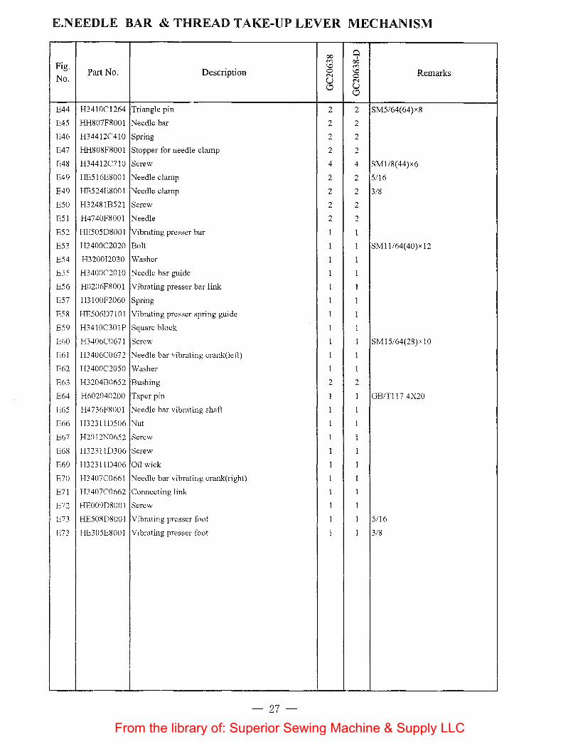
E.NEEDLE BAR & THREAD TAKE-UP LEVER MECHANISM
00 Q I
Fig. ("') 00 \0 ("')
Part No. Description 0 \0 Remarks No. N 0 u N
0 u 0
E44 H3410Cl264 Triangle pin 2 2 SM5/64(64)x8
E45 HH807F8001 Needle bar 2 2
E46 H34412C410 Spring 2 2
E47 HH808F8001 Stopper for needle clamp 2 2
E48 H34412C710 Screw 4 4 SM1/8(44)x6
E49 HE516E8001 Needle clamp 2 2 5/16
E49 HE524E8001 Needle clamp 2 2 3/8
E50 H32481B521 Screw 2 2
E51 H4740F8001 Needle 2 2
E52 HE505D8001 Vibrating presser bar 1 1
E53 H3400C2020 Bolt 1 1 SM11164(40)x12
E54 H3200l2030 Washer 1 1
E.i5 H3400C2010 Needle bar guide 1 1
E56 H0206F8001 Vibrating presser bar link 1 1
E57 H3100F2060 Spring 1 1
E58 HE50GD7101 Vibrating presser spring guide 1 1
E59 H3410C301P Square block 1 1
E60 H3406C0671 Screw 1 1 SM15/64(28)x 10
E61 H3406C0672 Needle bar vibrating crank(left) 1 1
EG2 H3400C2050 Washer 1 l
E63 H3204B0652 Bushing 2 2
E64 H602040200 Taper pin 1 1 GB/T117 4X20
E65 H4736F8001 Needle bar vibrating shall 1 1
EGG H32311D506 Nut 1 1
E67 H2012N0652 Screw 1 1
E68 H32311D306 Screw 1 1
E69 H32311D406 Oil wick 1 1
E70 H3407C0661 Needle bar vibrating crank(right) 1 1
E71 H3407C0662 Connecting link 1 1
E72 HE009D8001 Screw 1 1
E73 HE508D8001 Vibrating presser foot 1 1 5/16
E73 HE305E8001 Vibrating presser foot 1 1 3/8
I
I
-27-
From the library of: Superior Sewing Machine & Supply LLC

F. TOP FEED ROCK SHAFT MECHANISM
2 3 4
\ 34 33 32 31 30 29 28 26
-28-
13
~14
~15
From the library of: Superior Sewing Machine & Supply LLC

F.TOP FEED ROCK SHAFT MECHANISM
00 Ci I
Fig. M 00 \D M
Part No. Description 0 \D Remarks No. N 0 u N
"' u 0
FOl H4706G8001 Feed regulatcr cam 1 1
F02 HA113F0684 Screw 2 2 SM15/64 (28) x8.5
F03 H3200F2020 Screw 1 1 SM15/64 (28) X12
F04 H4707G8001 Link 1 1
FOS HA100G2070 Eccentric shaft 1 1
F06 H4709G8001 Reverse stitch shatl (upper) 1
F06 H4909G8001 Reverse stitch shaft (upper) 1
F07 H3207F0671 Arm 1
F07 H4905G8001 Arm 1
F08 HA800F2020 Screw 1 1
F09 HA100F2110 Spring Washer 1
FlO HA113F0684 Screw 2
I Fll H4711G8001 Reverse sewing lever 1
Fll H4906G8001 Reverse sewing lever 1
F12 H3207F0672 Screw 1 1 SMll/64 (40) x8.5
F13 H4710G8001 Spring 1 1
F14 H3200F2050 Guide plate 1
F15 HA300C2030 Screw 1 SMll/64 (40) x8
F16 H3200F2110 Spring 1 1
F17 HA700F2030 Pin 1 1
F18 HA720F0686 Screw I 1 SM3116(28)x 18
F19 HA720F0685 Bushing 1 1
F20 H4910G8001 Stitch length indicating plate 1 1
F21 HA7421F120 Dial 1 1
F22 HA720F0683 Stopper pin rclea~ing lever 1 1
F23 HA720F0687 Coil spring 1 1
F24 HA.I09F0671 Screw bar 1 1
F25 HA109F0674 0-ring 1 1
F26 H3206F0662 Pin 1 1
F27 H415050200 Screw 1 1 GB/T70.1 M5x20
F28 H428050060 Screw 2 2 GB/T77 M5x6
F29 H471408001 Reverse sewing crank 1 1
F30 H4715G71Ul Collar 1 1
F31 HA3411D308 Screw 2 2 SM15/64(28)x7
F32 H4719<:J8001 Felt 1 1
f33 H4720G8001 R verse block 1 1
F34 H4721G8001 Felt 1 1
F35 H4722G8001 Square block 2 2
F36 H4723G8001 1Guide plate 2 2
F37 lli\300C2ii:''l jS;:rew 4 4 SM11/64 (40) x8
I _ _j I I
-29-
From the library of: Superior Sewing Machine & Supply LLC

G.LOWER SHAFT & FEED ROCK SHAFT MECHANISM
13 14 15 1 8 19 20 21 22 23 I
1 2 4 5
I
16 17
~
58
37 26
li 53 54 43 42 40 35 34 33 32 31 30
-30-
From the library of: Superior Sewing Machine & Supply LLC

G.LOWER SHAFT & FEED ROCK SHAFT MECHANISM
~r=T - "'-
00 'il Fig. Part No. !
C') 00 \C) C')
Description 0 \C) Remarks No.
(') 0 u (')
0 u 0
-· 001 H4706H8001 Lower shaft bushing (left) 1 1
002 H4707H8001 Oil wick 1 1
003 H4708H8001 Lower shaft 1 1
004 H4710H8001 Feed eccentric cam 1 1
005 H3205H0654 Screw 1 1 SM1/4(40)x5
006 H4712H8001 Lower shaft bushing (right) 1 1
007 H4713H8001 Oil wick 1 1 ' I Gil H2405D0664 Screw 2 2 SM15/64(28)x14
012 H4717H8001 Feed eccentric 1 1
013 H4719H8001 Needle bearing 1 1
014 H4718H8001 Feed connecting rod 1 1
G15 H007009260 C-type stop ring 1 1 GB/T894.1 26
016 H4720H8001 Oil wick 1 1
G17 H4721H8001 Shaft 1 1
018 H4722H7101 Lower shaft bushing complete (middle) 1 1
Gl9 H4725H8001 Bushing 1 1
G20 HA105D0662 Screw 1 1 SM1/4 (40) x4
G21 H3205H0654 Screw 1 1 SM1/4(40)x5
G22 H4723H8001 Ball bearing 1 1
G23 H4727H8001 Bearing holder 1 1
G24 HA7311C306 Screw 3 3 SM9/64 (40) x7
G25 H4728H8001 Washer 1 1
G26 H4729H8001 Screw 1 1 M6
G27 I-1003058060 Nut 1 1 GB52008 M6
I G28 H4731H8001 Feed connection crank (right) 1 1
G29 H2012N0652 Screw 1 1 SM114(24)x 16
G30 HA100G2120 Feed rock shaft bushing 2 2
G31 H4708D8001 Screw 2 2 SMJ/4(24)x13
G32 HA108GD661 Collar 2 2
G33 HA105D0662 Screw 4 4 114(40)x4
G34 JI2012N0652 Screw 1 1 SM114(24)x16
G35 H4736H8001 Feed connection crank (middle) 1 1
G36 H4737H8001 Link 1 1
G37 I-1007013050 E-type stop ring 2 2 GB/T896 5
G38 H4738H8001 Pin 1 1
G39 H4739H8001 Oil wick 1 1
G40 H3204G0651 Feed rock shaft 1 1
G41 H4740H8001 Felt 2 2
G42 Il3204G0031 Oil wick I 1
G43 H3200G2030 Clip 1 1
G44 HA104G0012 Screw 2 2 SM3/16 (28) x12
G45 I-1320501032 Feed connection crank (let!) 1
G45 H4905H8001 Feed connection crank (letl) 1
-31-From the library of: Superior Sewing Machine & Supply LLC

G.LOWER SHAFT & FEED ROCK SHAFT MECHANISM
00 Q I
Fig. <') 00 \0 <')
Part No. Description 0 \0 Remarks No. N 0 u N
0 u 0
G46 H32243G205 Feed bar shaft 1 1
G47 H3205G0662 Oil wick 1 1
G48 H32211G205 Bolt 2 2 SM1/8(40)x7
G49 H429050050 Bolt 1 1 GBfr78 M5x5
G50 H32211GC05 Feed bar 1
G50 H4942H8001 Feed bar 1
G51 H3200H2040 Screw 1 1 SM15/64(28)x 17
G52 H2013J0065 Washer 1 1
G53 H003002030 Nut 1 1 GB/T6170 M3
G54 H429030140 Screw 1 1 GB/T78 M3x14
G55 H3205H0653 Screw 1 1 SMl/8 (44) X4
G56 H3205H0652 Felt 1 1
G57 H4743H8001 Feed bar forked connection 1 1
G58 H4748H8001 Feed dog 1 5/16
G58 H4749H8001 Feed dog 1 3/8
G58 H4948H8001 Feed dog 1 5/16
G58 H4949H8001 Feed dog 1 3/8
G59 H007009070 C-type stop ring 1 1
- 32 --
From the library of: Superior Sewing Machine & Supply LLC

H.HOOK SADDLE MECHANISM
-33-
28 29
From the library of: Superior Sewing Machine & Supply LLC

H.HOOK SADDLE MECHANISM(LEFT) ~
00 0 I
Fig. M 00 \C) M
Part No. Description 0 \C) Remarks No. N 0 u N 0 u
0
HOI H3304I065I Hook saddle (right) I
HOI H4906I800I Hook saddle (right) I
H02 H3207I066I Screw 2 2 SMI5/64(28)x30
H03 H3207I0066 Bushing 2 2
H04 H3500I20IO Hook complete 2
H04 H9304J7IOI Hook complete 2 HSH-I2MC (3)
H05 H4922I800I Spring 2
H06 H3306I0067 Bobbin 2
H06 H9305J800I Bobbin 2 BO-II2 (A) M
H07 H3505I065I Bobbin case 2
H07 H9306J800I Bobbin case 2 CP-I2MC (3)
H08 H3204I0656 Oil wick 2 2 2.5x I5
H09 H32I53I504 Bobbin case opener holder pin 2 2
HIO H32I53I204 Screw 2 2 SM3/16(32)x7.8
HII H33I31I204 Link 2 2
HI2 H33I31Il04 Bobbin case opener holder 2 2
HI3 H2004J0067 Screw 2 2 SM9/64 (40) x7
HI4 H3200I2030 Washer 2 2
HI5 H3305I0066 Opener 2 2
HI6 H005008050 Spring washer 2 2 GB/T93 5
H17 HA104G0658 Nut 2 2 SM3/I6(32)
HI8 H33I21I204 Spacer 2 2
HI9 H33I21Il04 Hook shaft bushing (upper) 2 2
H20 H3204I0657 Screw 2 2 SM3/16(28)x14.5
H2I H4705I800I Gear (small) 2 2
H22 HAI05D0662 Screw 6 6 SMl/4 (40) X4
H23 H4706I800I Gear (large) 2 2
H24 H3204I0653 Hook shaft bushing (lower) 2 2
H25 H20I3J0065 Washer 2 2
H26 H3200I2050 Screw 2 2 SM114(24)x23
H27 H3204I0658 Screw 2 2 SM3/I6(28)x43
H28 H3204I0659 Nut 2 2 SM3116(28)
H29 H0050I4050 Spring washer ~ 2 GB/T955 5 L
H30 HA305E0662 Screw 4 4 SMI5/64 (28) x4.5
H31 HA307C0662 Screw 2 2 SMl/4 ( 40) x6
H32 H4707I800I Screw 2 2 SM1/4(40)x6.5
H33 H3307I068I Hook saddle (left) I
H33 H49I7I800I Hook saddle (left) 1
-34-
From the library of: Superior Sewing Machine & Supply LLC

I.KNIFE MECHANISM (1)
3
\\ 20 18 (8) 17 16 (6)
(15) (14) (11)
-- 35-
From the library of: Superior Sewing Machine & Supply LLC

tKNIFE MECHANISl\'l (1) ~~
00 0 I
Fig. M 00 1.0 M
Part No. Description 0 1.0 Remarks No. N 0 u N
c.:; u c.:;
f-- ·--· --IOl H4905J8001 Screw 2
I02 H4906J8001 Bolt 2 SMll/64 (40) x12
I03 H4907J8001 Trimming knife holder 2
104 · H4908J800 1 Screw 6 SM9/64 (40) x4
105 H4909J8001 Fixed blade 2
106 H4914B8001 Screw 4 SM9/64 (40) X4
I07 H4911J8001 !Moved knife 2
108 H4912J8001 Screw 2 SMl/8 (44) x9.2
I09 H4913J8001 Screw 2 SM9/64 (40) X4.5
no H4914J8001 Spring plate 2
Ill H4915J8001 Screw 6 SM3/32 (56) x3.8
I12 H4916J8001 Reversing spring 2
Il3 H4917J8001 Guide 1
!14 H4920J8001 Roller 2
!15 H4921J8001 Lever 2
!16 H4922J8001 Cover 1
!17 H4923J8001 Guide (right) 1
I18 H4924J8001 Knife pad (right) 1
I19 H4925J8001 Screw 1 SM9/64 (40) X9.5
I20 H4926J8001 Knife pad (left) 1
I21 H4927J8001 Cover 1
-36-
From the library of: Superior Sewing Machine & Supply LLC
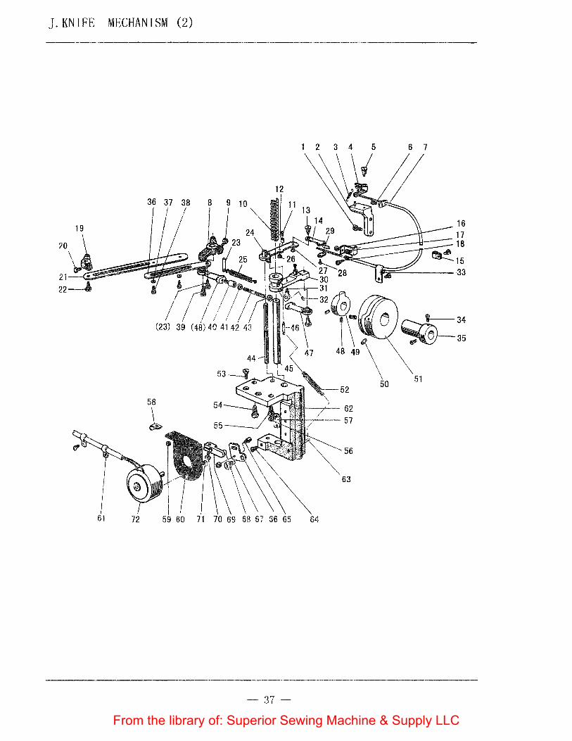
KNIFE MECHANISM (2) J.
36 37
19
20~:::::-.:::, ~~'if!i!i.~~~ 21 •
22~
I 61 72
56
63
~---
-- 37-
6 7
16
i-34
~35 \
51
From the library of: Superior Sewing Machine & Supply LLC

J .KNIFE MECHANISM (2)
00 0 I
Fig. (") 00 \D (")
Part No. Description 0 \D Remarks No. N 0 u N
0 u ! 0
.. 101 HA300C2030 Screw 2 SMll/64 (40) x8
102 H4915K7101 Thread releading bracket 1
J03 H4918K8001 Spring l
104 l14919K7101 Threat~ releading plate I l
I J05 H2400I2040 Screw 1 SM11164 (40) xs
106 HA300B2170 Screw 4 SMll/64 (40) X8
J07 H4923K7101 Flexible wire complete 1
J08 H4912K8001 Arm 1
J09 H4913K8001 Bolt 1 SM15/64 (28) x12.5
JIO H4945K8001 Spring 1
Jl1 H4950K8001 Screw 1 SMll/64 (40) X3.6
J12 H4949K8001 Roller 1
Jl3 H4952K8001 Screw 1 SM3/16 (28) x5
Jl4 H4953K8001 Mounting plate 1
J15 HA700Q0030 Nylon clip 1
J16 H4925K8001 Mounting plate 1
J17 H003002050 Nut 2 GB/T6170 M5
Jl8 HA300C2030 Screw 1 SMll/64 (40) x7
J19 H4908K8001 Arm 1
J20 H4907K8001 Bolt 1 SM15/64 (28) X 12.5
J21 H4906K8001 Link 1
J22 H4905K8001 Screw 2 M5(0.5)x7.5
123 HA100H2080 Pin type 1
J24 H4946K7101 Thread releasing lever 1
125 H4943K8001 Spring 1
J26 H4951K8001 Nut 1 SMll/64 C 40)
127 H4954K8001 Nut 1 SM3/16 (28)
128 H4956K8001 Screw 2 SMl/8 (44) x7
J29 H4955K8001 Bushing 1
J30 H4957K7101 Vibrating crank 1
J31 H4944K8001 Screw 1 SMll/64 (40) x5.5
J32 H3205G1114 Screw 2 M5x5
J33 HA708P0668 Nylon clip 1
134 HA113F0684 Screw 2 SM15/64 (28) x8.5
135 H4931K8001 Bushing 1
136 H4909K8001 Link 1
137 H005001050 Washer 1 GB/T97.1 5
138 H4911K8001 Bolt 2
139 H4936K8001 Screw 2 M5(0.5)x8.5
J40 H4987K800l Bolt 1
J41 H4940K8001 Nut (left) 1 M5(letl)
J42 H4939K8001 Bolt 1
J43 H003002050 Nut (right) 1 GB/T6170 M5 '-· -
-38-
From the library of: Superior Sewing Machine & Supply LLC

J.KNIFE MECHANISM (2)
00 0 I
Fig. M 00 ID M
Part No. Description 0 ID Remarks No. N 0
u N C) u
C)
144 H4964K8001 Shaft 1
145 H4963K8001 Shaft 1
146 H4985K8001 Screw 1 SM11/64 (40) x4
147 H3405D0663 Ball joint (right) 2
J48 H3205G1114 Screw 4 M4x4
149 H4934K8001 Cam 1
150 HA710E0692 Screw 2 SM1/4 (40) x9.5
151 H4932K8001 Cam 1
152 H4986K8001 Spring 1
153 H411050160 Screw 2 GB!f819.1 M5x16
154 H2012N0652 Screw 1 SM1/4 (24) x16
155 H4983K8001 Screw 1 SM1/4 (24) x13
156 H4967K8001 Screw 3 SM11164 (40) x7
157 H4966K8001 Stopper 1
158 H4981K8001 Holder 1
159 H003008050 Nut 2 GB!f6172.1 M5
160 H4977K8001 Mounting plate 1
161 H4980K8001 Holder 2
162 H4965K8001 Set plate 1
163 H3700E2080 Pin type 1
164 H4969K8001 Screw 1 SM11/64 (40) x8.5
165 H4970K8001 Screw 1 SM11/64 (40) x6
166 H4971K8001 Lever 1
167 H4972K8001 Screw 1 SM11164 (40) x6.8
168 H4973K8001 Pin 1
169 H4974K8001 Ann 1
170 HA111G0683 Screw 1 SM11164 (40) X12
171 HA7111N304 Nut 1 SM11/64 (40)
172 H4979K8001 Solenoid complete 1
-39-
From the library of: Superior Sewing Machine & Supply LLC

K. TOUCH BACK AND DETECTOR MECHANISM
2 3 4 6 7 8 9 10 11 12
-40-
From the library of: Superior Sewing Machine & Supply LLC

K.TOUCH BACK AND DETECTOR MECHANISM
00 Ci I
M 00 Fig. \0 M
Part No. Description 0 \0 Remarks N 0 No. u N C) u
C)
K01 H8505L7101 Touth switch complete 1
K02 H4918L8001 Screw 4 M5
K03 HA700Q0030 Holder 2
K04 H4922L8001 Holder I
K06 H007009300 Retaining ring C-type 1 GB!f894.1 30
K07 HA700R0060 Washer 1
K08 HA700R0050 Support spring 1
K09 HA700R0040 Spacer B 1
K10 H4928L8001 Speed command disk F20 (up) I
K11 HA700R0030 Spacer A 2
K12 H4930L8001 Speed command disk F11 (down) I
Kl3 HA110D0672 Screw 2 SM15/64 (28) x12
K14 H4931L8001 Pulley (complete) I
K15 HA703R0067 Washer 1
K16 HA703R0065 Detector bracket (complete) 1
K17 HA341!D308 Screw 1 SMI5/64 (28) x7
K18 H4936L8001 Lever 1
K19 HAI13F0684 Screw 1 SM15/64 (28) x7.5
K20 H4937L8001 Screw 1 SM15/64 (28) X6
K21 H4938L8001 Rubber ring 1
K22 H4939L8001 Spring 1
K23 H4940L8001 Nut 2
K24 H4941L8001 Screw 2 SM15/64 (28) x[4
K25 H4942L8001 Nut 1
K26 H4943L8001 Solenoid (complete) 1
K27 lil 02080120 Blot 2 GB/T5781 M8x!2
K28 H4945L8001 Set plate 1
K29 H005008060 Spring washer 2 GB!f93 6
K30 H003002060 Nut 2 GB!f6170 M6
K31 H4948L8001 Link 1
K32 H4949L8001 Blot 1 SM15/64 ( 28) x13
K33 H4950L8001 Arm 1
K34 HA300C2030 Screw 2 SM11!64 C 40) xs
-41-From the library of: Superior Sewing Machine & Supply LLC

L.OIL LUBRICATION MECHANISM
1 2 3
45~
39
37 (1 0) 36 (15)
6 7 8 9
\
10
--+---11
12 __ ___,,J--- 13
::---~.c.-- (32)
15 14 181716
19
-42-
From the library of: Superior Sewing Machine & Supply LLC

L.OIL LUBRICATION MECHANISM
l I Fig.
! No. '
L01
L02
L03
L04
LOS
UJ6
L07
L08
L09
L!O
Lll
Ll2
L13
I L14
Ll5 '
I L1G
Tll
I
Ll/i
l 19
.. 1.0 I 1]
I L22
! L23
L24
L.~5
I 2(J
r ·-~ _..::/
L21l
L29
LJO
Ul
u: -~ :
L 15
UG
Part No. Description
H32175B304 Felt
H4705J7101 Oil pipe complete
H3204K0011 Oil reservoir complete
H411040160 Screw
H4707J8001 Holder
H4708J8001 Oil pipe <D 3 x 1 x 400
H4709J8001 Oil pipe <D 5 x 1 x 360
H4711J7101 Oil reservoir complete
H471JJ8001 Hoider
HA7311CC06 Screw
HA.l 0012050 Spring washer
H2000MO 110 Holder
H 4 714.1800 I Holder
I !::~,~~~3~~::6 :::.:r I .
1 . '~'KlJ"! j 1 r'c'·"·w
1 fi.r: 1:<001 1Btu<hi:1g 1
H32l.'K0696,0il pipe
Hl100I2070 !Pin
: H1 1 · :u::090 jsprinr
I' H111Jl<12110 Springholder
H3204D651 0 Screw
I H32l5K0693 Screw
! H32J5!(fJ(;(l2 Filter
lll3' 5K0694 "'·~r~". I H47 :U7101 !Mounting plate conmkle
1 H32i 5K!Jii95 !Holder
H3200KO 17(1 I Holder
J-L\ "/ ~ 1 ll ~CU(; ~)cre\V
H3210~06~4~l:old~r ..
I H3210K06; 1 Cd p:pc Jllmt
HAiOOE2150 Screw
I l 14721J>lfl(J] (;il pipe <D3xl x')()
I !;472:::1800 1 joil pipe Cl)3x 1 xJor l I2U\,('''-'\L'; lO I Holder
i L37 l !32,; l<Hlri8 Oil reserv,m complete
I UX I H3 ~ ' ,:o UW Oil Wlck <D2 5 <35
u; H4-'~: "'' I l I
' j :<
·-- 43 -
00 ,...., 'D 0 N u 0
1
1
1
2
1
1
1
1
1
7
1
1
1
1
I g
f j i ' i I 1 I I I
1 l I I
I
I
1
l 1 I ! ' \ J
4
')
3
0 I
00 ,...., \D 0 N u 0
1
1
1
2
1
l
1
1
1
7
1
1
1
1
R
2
]
1
1
1
1
1
1
1
Remarks
GB/T819.1 M4xJ6
SM9/64 (40~ x[}.5
I l Sl\19/64 ( 40) X4. 5
I
!
SMHI (44) x4.5
SM9/64 ( 40) :.c)
SM9/64 ( •iO) x6.5
4 SMI l/64 (40) x9
2
3
From the library of: Superior Sewing Machine & Supply LLC

L.OIL LUBRICATION MECHANISM
00 0 I
Fig. M 00 'D ('<')
Part No. Description 0 'D Remarks No. N 0 u N c.:;; u
0
L45 HA300C2030 Screw 1 1
-44-
From the library of: Superior Sewing Machine & Supply LLC

M.ACCESSORIES
13-P
19
/ 41 40 39
10
26
33
_____ " _______ _ -45-
5
6
231l
----------27
29
-·--
From the library of: Superior Sewing Machine & Supply LLC

M.ACCESSORIES
00 0 I
Fig. ("<") 00 \0 ("<")
Part No. Description 0 \0 Remarks No. N 0 u N
0 u Cj
1-· ·-MOl H4740F8001 Needle DPx17-23 6 6
M02 H3209L8001 Socket wrench 1
M03 H3208L8001 Socket wrench 1 1
M05 H3306I0067 Bobbin 4
M05 H9305J8001 Washer 4 BO-B872 (A)
M06 H3200L0050 Screw 2 2
M07 H801045200 Vibration preventing rubber 4 4 GB/T99 4.5x20
M08 H4700K0020 Vibration preventing rubber 2 2
M09 H4700K0030 Vibration preventing rubber 2 2
M10 HA100J2110 Oiler 1 1
Mll HA100J2140 Screw driver (middle) 1 1
M12 HA100J2150 Screw driver (small) 1 1
M13 H3207L0065 Thread a needle kit 1 1
Ml4 HA704S0654 Adjusting plate for speed command disk 1
M17 H3200L0130 Oil can I 1
Ml8 H3200L0120 Cotton stand 1 1
M19 H3300L0040 Bobbin winder 1 1
M20 H200800068 Belt cover 1
M21 HA300C2170 Screw 2 SM11/64(4Q)x8
M22 HA300J2280 Screw 2 2 SM11/64(28)x8
M23 HA300J2250 Screw 1 M4x8
M24 H2405K6601 Belt cover complete 1
M24 H4953N7101 Belt cover complete 1
M25 H003008040 Nut 1 GB/T6172.1 l\14
M26 HA305J0665 Belt cover 1 1
M27 HA100J2120 Magnet block for reservoir 1 1
M28 HA307J0067 Hinge complete 2 2
M29 HA300J2070 Screw driver (large) 1 1
M30 H3214L0067 Small parts 1 1
M31 H3214L2011 Knee lifter pin 1 1
M32 H3213L0662 Knee lift shaft 1 1
M33 HAI04J0657 Spring 1 1
M34 HA106J0664 Bolt 1 1
M35 HAI04J6510 Nut 2 2
M36 HA104J0659 Screw 2 2
M37 H3213L0664 Knee lifter crank I 1
M38 H007013090 E-type stop ring 1 1 GB/T896 9
M39 HA104J0653 Washer I 1
M40 HA104J0652 Screw 1 1
M41 H3213L0661 Oil reservoir 1 1
M42 HA100J2180 Vinyl cover 1 I
-46-
From the library of: Superior Sewing Machine & Supply LLC

From the library of: Superior Sewing Machine & Supply LLC

SHANGHAI HUIGONG N0.3 SEWING MACHINE FACTORY
ADD: 1418, Yishan Road, Shanghai, China
Zip Code: 201103
Overseas Business: TEL: 86-21-64853303 FAX: 86-21-64854304
E-mail:[email protected] http://www.highlead.com.cn
The description covered in this manual is subject to change for improvement of the commodity without notice
2005.1. Printed
From the library of: Superior Sewing Machine & Supply LLC