high-power xenon light source - ocean...
TRANSCRIPT
000-00000-000-02-A
High-Power Xenon Light Source HPX-2000
Installation and Operation Manual Document Number 000-10000-080-02-201207
Offices: Ocean Optics, Inc. World Headquarters 830 Douglas Ave., Dunedin, FL, USA 34698 Phone 727.733.2447 Fax 727.733.3962 8 a.m.– 8 p.m. (Mon-Thu), 8 a.m.– 6 p.m. (Fri) EST
Ocean Optics Germany Maybachstraße 11, D73760, Ostfildern, Germany Phone +49 (0)711 34 16 96-0 Fax +49 (0)711 34 16 96-85
E-mail: [email protected] (General sales inquiries)
[email protected] (Questions about orders) [email protected] (Technical support)
Protective Eye Wear Must Be Worn When Using This Instrument - Intense Ultraviolet Radiation Present
See Important Safety Notices inside. WARNING

Copyright © 2010 Ocean Optics, Inc. All rights reserved. No part of this publication may be reproduced, stored in a retrieval system, or transmitted, by any means, electronic, mechanical, photocopying, recording, or otherwise, without written permission from Ocean Optics, Inc. This manual is sold as part of an order and subject to the condition that it shall not, by way of trade or otherwise, be lent, re-sold, hired out or otherwise circulated without the prior consent of Ocean Optics, Inc. in any form of binding or cover other than that in which it is published. Trademarks Microsoft, Windows, Windows 95, Windows 98, Windows Me, Windows NT, Windows 2000, Windows XP and Excel are either registered trademarks or trademarks of Microsoft Corporation. Limit of Liability Every effort has been made to make this manual as complete and as accurate as possible, but no warranty or fitness is implied. The information provided is on an “as is” basis. Ocean Optics, Inc. shall have neither liability nor responsibility to any person or entity with respect to any loss or damages arising from the information contained in this manual.
000-10000-080-02-201207 A
Important Safety Notices 1. Do not remove or modify any installed safety device on this equipment. Doing so will void your
warranty and create an unsafe operating environment.
2. Dangerous voltages are present in this device. There are NO user serviceable parts inside.
3. Only allow qualified personnel to service this unit.
4. Do not use the unit if it is damaged in any way. Contact your dealer for repair or replacement information.
5. Always screw in the fiber optic cables before starting the instrument.
Protective eyewear must be worn when using this equipment. Intense ultraviolet radiation is present. Never look directly into the light beam, as this can cause eye damage. WARNING
Warranty Ocean Optics warrants to the original user of this instrument that it shall be free of any defects resulting from faulty manufacture of this instrument for a period of 12 months from the original data of shipment. There are no warranties for the Xenon Bulb (REPAIR-HPX-1) and the Xenon-Bulb-Module (HPX-2000-BM).
This instrument should not be used for any Clinical or Diagnostic purposes. Data generated in these areas is not warranted in any way by Ocean Optics Germany GmbH. Any defects covered by this Warranty shall be corrected either by repair or by replacement, as determined by Ocean Optics Germany GmbH.
There are no warranties that extend beyond the description herein.
This Warranty is in lieu of, and excludes, any and all other warranties or representations expressed, implied, or statutory, including merchantability and fitness, as well as any and all other obligations or liabilities of Ocean Optics including, but not limited to, special or consequential damages. No person, firm, or corporation is authorized to assume for Ocean Optics. Any additional obligation or liability not expressed provided for herein except in writing duly executed by an officer of Ocean Optics:
Ocean Optics Germany GmbH Maybachstraße 11 D-73760 Ostfildern Tel.: +49 (0)711 34 16 96-0 • Fax.: +49 (0)711 34 16 96-85 e-mail: [email protected]

Important Safety Notices
B 000-10000-080-02-201207

000-10000-080-02-201207 i
Table of Contents
About This Manual .............................................................................................................iii Document Purpose and Intended Audience .............................................................................. iii What’s New in this Document ................................................................................................... iii Document Summary .................................................................................................................. iii Product-Related Documentation ............................................................................................... iii
Upgrades ............................................................................................................................iv Chapter 1: Setup ................................................................................... 1
Overview .............................................................................................................................1 Unpacking the HPX-2000...................................................................................................2 Contents .............................................................................................................................2 Connecting the Fiber Optic Cable ......................................................................................2
Chapter 2: HPX-2000 Specifications .................................................. 3
Operating Environment ......................................................................................................3 HPX-2000 Components .....................................................................................................3
Front Panel ................................................................................................................................ 4 Rear Panel ................................................................................................................................. 5
Specifications .....................................................................................................................6 Parts List .............................................................................................................................6 Pinout Information ..............................................................................................................7
Pinout Diagram .......................................................................................................................... 7

Table of Contents
ii 000-10000-080-02-201207
Chapter 3: Operating Instructions ...................................................... 9
Operating the Xenon Lamp ................................................................................................9 Starting Main Power .................................................................................................................. 9 Starting the Lamp ...................................................................................................................... 9 Turning the Lamp Off ................................................................................................................. 10 Warming Up the Lamp ............................................................................................................... 10
Operating the TTL Shutter .................................................................................................10 Automatic Operation .................................................................................................................. 10 Manual Operation ...................................................................................................................... 10
Operating the Filter Slit ......................................................................................................10 Chapter 4: Troubleshooting ................................................................ 11
Appendix A: Bulb Replacement ......................................................... 13
Replacing the Bulb .............................................................................................................13
Index ...................................................................................................... 15
000-10000-080-02-201207 iii
About This Manual
Document Purpose and Intended Audience This document provides you with an installation section to get your system up and running.
What’s New in this Document This version of the High-Power Xenon Light Source Installation and Operation Manual updates the part number for the bulb.
Document Summary Chapter Description
Chapter 1: Setup Contains a list of package contents and unpacking instructions. Also contains instructions for connecting the fiber optic cable.
Chapter 2: HPX-2000 Specifications Contains operating environment specifications, as well as other physical details of the product, a parts list, and pinout information for the15 DB-15 connector.
Chapter 3: Operating Instructions Provides instructions for operating the Xenon lamp and the TTL shutter.
Chapter 4: Troubleshooting Contains a table of troubleshooting information.
Appendix A: Bulb Replacement Provides instructions for changing the bulb.
Product-Related Documentation You can access documentation for Ocean Optics products by visiting our website at http://www.oceanoptics.com. Select Technical → Operating Instructions, then choose the appropriate document from the available drop-down lists. Or, use the Search by Model Number field at the bottom of the web page.
You can also access operating instructions for Ocean Optics products on the Software and Technical Resources CD included with the system.
Engineering-level documentation is located on our website at Technical → Engineering Docs.

About This Manual
iv 000-10000-080-02-201207
Upgrades Occasionally, you may find that you need Ocean Optics to make a change or an upgrade to your system. To facilitate these changes, you must first contact Customer Support and obtain a Return Merchandise Authorization (RMA) number. Please contact Ocean Optics for specific instructions when returning a product.

000-10000-080-02-201207 1
Chapter 1
Setup
Overview The following sections provide instructions on unpacking and setting up your HPX-2000 High-Power Light Source.
Before using the HPX-2000 for the first time check for transport damage. Be sure to adhere to all warnings on the unit and in this manual.
HPX-2000 High-Power Light Source

1: Setup
2 000-10000-080-02-201207
Unpacking the HPX-2000 ► Procedure
1. Unpack your lamp assembly carefully. Although the lamp is rigidly mounted, dropping this instrument can cause permanent damage.
2. Inspect the outside of the instrument and make sure that there is no damage. Do not use the instrument if damage is present. Contact your dealer for repair or replacement information, if necessary.
3. Use this instrument in a clean laboratory environment (see Operating Environment).
Contents Your HPX-2000 package should contain the following:
HPX-2000 High-Power Light Source Power cord UV safety goggles One IC-DB15-2 interface cable for shutter operation This manual
Connecting the Fiber Optic Cable ► Procedure
To connect the fiber optic cable to the HPX-2000,
1. Locate the cap on the front of the HPX-2000.
2. Lift the cap on the front of the HPX-2000 to expose the SMA connector.
3. Connect the fiber optic cable to the SMA connector.
000-10000-080-02-201207 3
Chapter 2
HPX-2000 Specifications
This section provides information on the operating environment, physical controls, and dimensions of the HPX-2000. It also provides pinout information for the connector.
Operating Environment The following table provides information on optimizing the operating environment of your HPX-2000.
Operating Environment The HPX-2000 Unit . . .
Moisture Is designed for operation in dry rooms only.
Ventilation Should be situated so that its location or position does not interfere with proper ventilation.
Heat Should be situated away from any device that emits excessive heat.
Object and Liquid Entry Should be positioned so that objects do not fall on top of the unit. Additionally, ensure that no liquids are spilled into the enclosure through openings.
HPX-2000 Components The following sections describe the components located on the front and rear of the HPX-2000 unit.
2: HPX-2000 Specifications
4 000-10000-080-02-201207
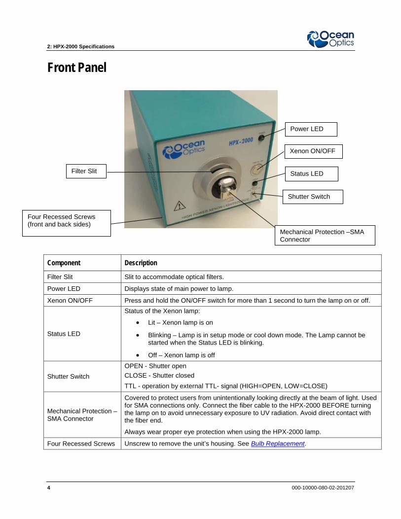
Front Panel
Component Description
Filter Slit Slit to accommodate optical filters.
Power LED Displays state of main power to lamp.
Xenon ON/OFF Press and hold the ON/OFF switch for more than 1 second to turn the lamp on or off.
Status LED
Status of the Xenon lamp:
• Lit – Xenon lamp is on
• Blinking – Lamp is in setup mode or cool down mode. The Lamp cannot be started when the Status LED is blinking.
• Off – Xenon lamp is off
Shutter Switch OPEN - Shutter open CLOSE - Shutter closed TTL - operation by external TTL- signal (HIGH=OPEN, LOW=CLOSE)
Mechanical Protection – SMA Connector
Covered to protect users from unintentionally looking directly at the beam of light. Used for SMA connections only. Connect the fiber cable to the HPX-2000 BEFORE turning the lamp on to avoid unnecessary exposure to UV radiation. Avoid direct contact with the fiber end.
Always wear proper eye protection when using the HPX-2000 lamp.
Four Recessed Screws Unscrew to remove the unit’s housing. See Bulb Replacement.
Filter Slit
Four Recessed Screws (front and back sides)
Mechanical Protection –SMA Connector
Power LED
Xenon ON/OFF
Status LED
Shutter Switch

2: HPX-2000 Specifications
000-10000-080-02-201207 5
Rear Panel
Component Description
Voltage Selector Switch Select regional voltage setting for lamp (AC 230-240V, 50/60Hz or AC 110-115V, 50/60Hz).
Main Power Switch Turn on to supply power to the HPX-2000. The Power LED lights when this switch is in the ON position.
Fuse Compartment Contains the fuse to protect the unit against overload:
Fuse Type: Miniature fuse 5 x 20 mm, 1.25 Amp slow blow
Input Terminal for Power Cord
Plug power cord into this terminal.
Note: Only connect the power cable to the lamp when the Main Power Switch is in the OFF position.
TTL Input SUB-D 15-pin connector for automatic shutter control.
Type Sign
Label providing lamp information: - Type High Power Xenon Lightsource - Version Europe / USA - Order-No. HPX-2000 - Serial-No. Xxxxxx - Mains connection 115 / 230V 47-63Hz - Power consumption 50 Watt - Max. Ambient Temperature 35°C
Cooling Fan Cools the interior of the HPX-2000. Do not obstruct.
TTL Input
Type Sign
Fuse Compartment
Cooling Fan
Main Power Switch
Voltage Selector Switch
Input Terminal for Power Cord
2: HPX-2000 Specifications
6 000-10000-080-02-201207
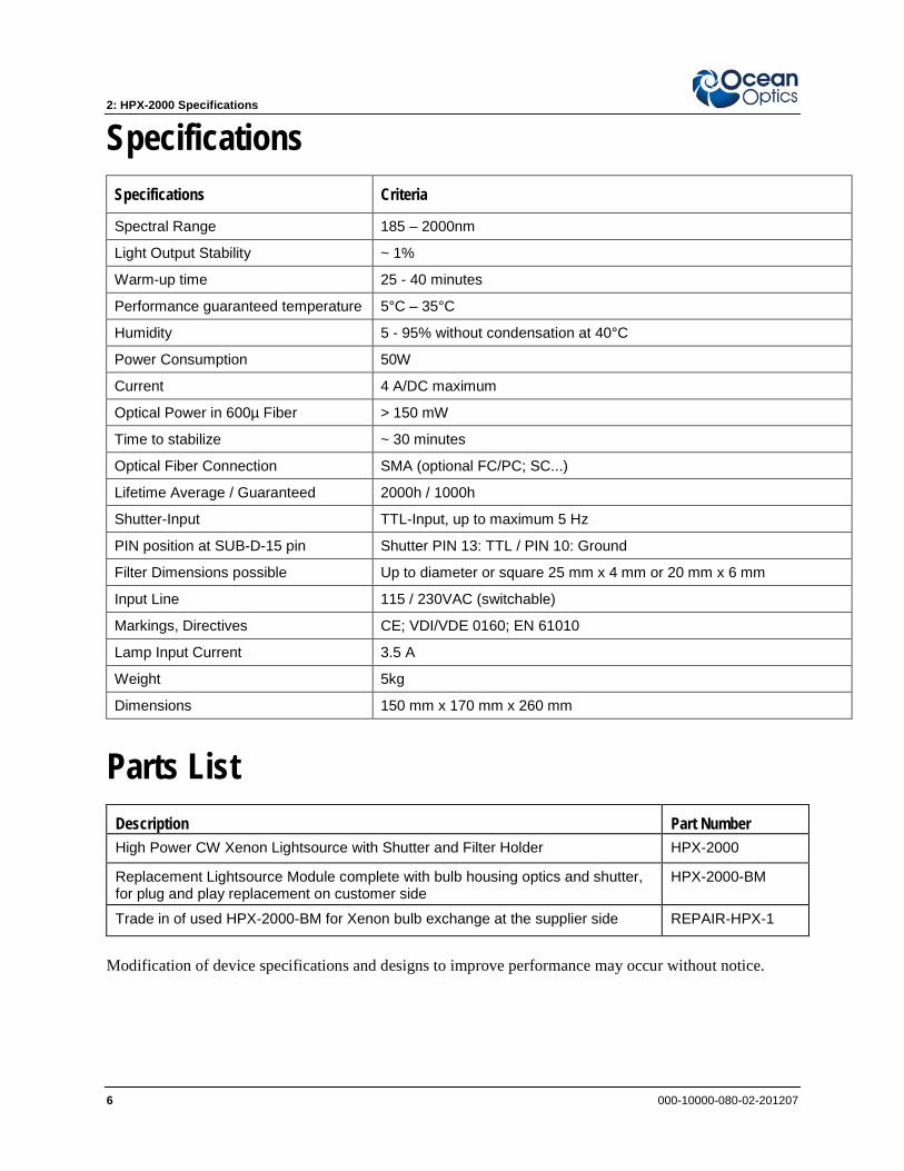
Specifications Specifications Criteria
Spectral Range 185 – 2000nm
Light Output Stability ~ 1%
Warm-up time 25 - 40 minutes
Performance guaranteed temperature 5°C – 35°C
Humidity 5 - 95% without condensation at 40°C
Power Consumption 50W
Current 4 A/DC maximum
Optical Power in 600µ Fiber > 150 mW
Time to stabilize ~ 30 minutes
Optical Fiber Connection SMA (optional FC/PC; SC...)
Lifetime Average / Guaranteed 2000h / 1000h
Shutter-Input TTL-Input, up to maximum 5 Hz
PIN position at SUB-D-15 pin Shutter PIN 13: TTL / PIN 10: Ground
Filter Dimensions possible Up to diameter or square 25 mm x 4 mm or 20 mm x 6 mm
Input Line 115 / 230VAC (switchable)
Markings, Directives CE; VDI/VDE 0160; EN 61010
Lamp Input Current 3.5 A
Weight 5kg
Dimensions 150 mm x 170 mm x 260 mm
Parts List Description Part Number High Power CW Xenon Lightsource with Shutter and Filter Holder HPX-2000
Replacement Lightsource Module complete with bulb housing optics and shutter, for plug and play replacement on customer side
HPX-2000-BM
Trade in of used HPX-2000-BM for Xenon bulb exchange at the supplier side REPAIR-HPX-1
Modification of device specifications and designs to improve performance may occur without notice.

2: HPX-2000 Specifications
000-10000-080-02-201207 7
Pinout Information The following table contains pinout information for the HPX-2000 Light Source:
Pin Description
1 na
2 na
3 na
4 na
5 na
6 na
7 na
8 na
9 na
10 Ground
11 na
12 na
13 TTL Signal – Shutter control
14 na
15 na
na = not applicable
Pinout Diagram

2: HPX-2000 Specifications
8 000-10000-080-02-201207
000-10000-080-02-201207 9
Chapter 3
Operating Instructions
Operating the Xenon Lamp
The following sections provide instructions on operating the Xenon lamp in the HPX-2000 Light Source. The HPX-2000 unit must be in a horizontal position for it to work.
Starting Main Power
► Procedure To apply main power to the unit,
1. Ensure that the proper voltage is set on the Voltage Selector Switch on the rear panel of the unit (see Rear Panel).
2. Ensure that the Main Power Switch is OFF. Then, connect the power cord to the Terminal Input on the rear panel of the unit.
3. Turn the Main Power Switch ON. The Power LED lights, indicating that the unit is receiving power. The Xenon bulb remains off after power-on.
Starting the Lamp Hold the Xenon ON/OFF switch down for 1 full second to illuminate the HPX-2000 lamp.
The lamp cannot be started when the Status LED is blinking. The Status LED blinks for about 5 seconds after the main power is switched on (main power switch is located on rear of unit).
WARNING
Protective eyewear must be worn when using this equipment - Intense ultraviolet radiation present. Never look directly into the light beam, as this can cause eye damage.
3: Operating Instructions
10 000-10000-080-02-201207
Turning the Lamp Off Turn the Xenon lamp off by holding the Xenon ON/OFF switch down for one full second. The Status LED blinks for about 30 seconds while the lamp cools down.
Warming Up the Lamp The HPX-2000 requires 25-30 minutes of operation to reach a state of thermal equilibrium. During this warm-up period, the intensity of the output power can vary substantially.
If applications require extreme intensity stability, the lamp should be warmed up for an additional 30-45 minutes. Once warmed up for this amount of time, the lamp will reach specified drift values.
Operating the TTL Shutter
Automatic Operation For automatic operation, plug the SUB-D 15-pin TTL connector into the appropriate socket on your spectrometer.
Manual Operation Manually set the operating mode of the HPX-2000 with the Shutter Switch as follows:
• OPEN - Shutter open
• CLOSE - Shutter closed
• TTL - Controlled over external TTL signal (HIGH=OPEN, LOW=CLOSE)
Operating the Filter Slit ► Procedure
1. Rotate the light beam protection cap to open the filter slit (see Front Panel).
2. Insert your filter with a maximum size of 1” round or square into the filter slit.
3. Rotate the light beam protection cap to close the filter slit.
000-10000-080-02-201207 11
Chapter 4
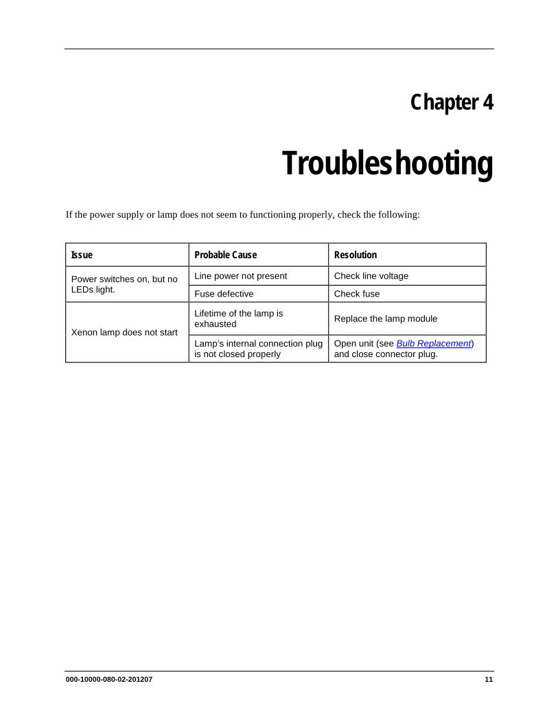
Troubleshooting If the power supply or lamp does not seem to functioning properly, check the following:
Issue Probable Cause Resolution
Power switches on, but no LEDs light.
Line power not present Check line voltage
Fuse defective Check fuse
Xenon lamp does not start
Lifetime of the lamp is exhausted Replace the lamp module
Lamp’s internal connection plug is not closed properly
Open unit (see Bulb Replacement) and close connector plug.

4: Troubleshooting
12 000-10000-080-02-201207
000-10000-080-02-201207 13
Appendix A
Bulb Replacement To order replacement bulbs for the HPX-2000, order item number HPX-2000-BM.
Replacing the Bulb
WARNING
During operation, the lamp reaches a temperature of approximately 250°C. Before changing the lamp’s bulb, please wait at least 20 minutes for cooling before touching the lamp module.
► Procedure
Follow the steps below to change the bulb in the HPX-2000:
1. Turn the Main Power Switch OFF.
Caution
Connection/disconnection of the power cord from the Xenon lamp MUST only be done when the Main Power Switch is turned OFF. Because the output of the power supply is not galvanically separated from the line voltage, the connecting lead for the Xenon lamp can carry a voltage >42 V when the Main Power Switch is turned ON.
2. Disconnect the power cord from the unit.
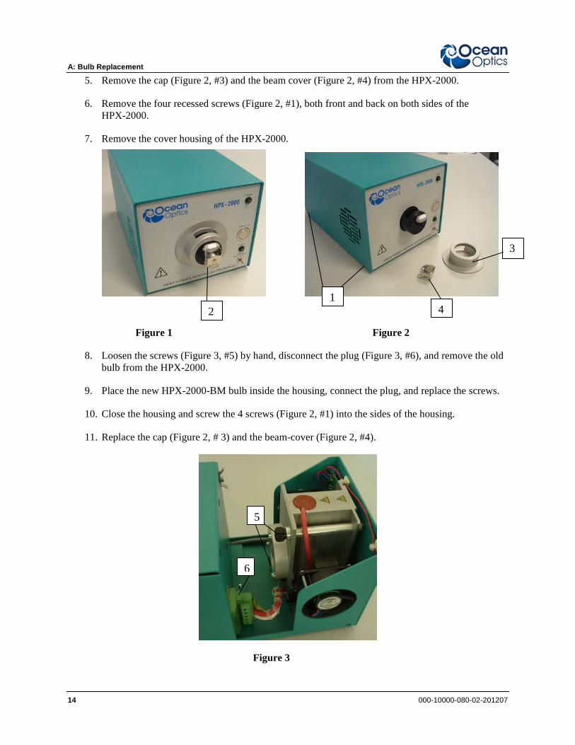
3. Rotate the cap (Figure 2, #3) until the round hole is at the bottom and a screw (Figure 1, #2) becomes visible.
4. Remove the screw using the 1.5 mm Allen wrench included with the replacement bulb.
A: Bulb Replacement
14 000-10000-080-02-201207
5. Remove the cap (Figure 2, #3) and the beam cover (Figure 2, #4) from the HPX-2000.
6. Remove the four recessed screws (Figure 2, #1), both front and back on both sides of the HPX-2000.
7. Remove the cover housing of the HPX-2000.
Figure 1 Figure 2
8. Loosen the screws (Figure 3, #5) by hand, disconnect the plug (Figure 3, #6), and remove the old bulb from the HPX-2000.
9. Place the new HPX-2000-BM bulb inside the housing, connect the plug, and replace the screws.
10. Close the housing and screw the 4 screws (Figure 2, #1) into the sides of the housing.
11. Replace the cap (Figure 2, # 3) and the beam-cover (Figure 2, #4).
Figure 3
1 2 4
3
6
5

000-10000-080-02-201207 15
Index B
bulb replacement, 13
C cable connection
fiber optic, 2 components, 3
front panel, 4 rear panel, 5
connecting the fiber optic cable, 2
D document
audience, iii purpose, iii summary, iii
F fiber optic cable
connecting, 2 filter slit, 10
O operating environment, 3
P package contents, 2
parts list, 6 pinouts, 7 product-related documentation, iii
S setup, 1 specifications, 3, 6
T troubleshooting table, 11 TTL shutter, 10
automatic operation, 10 manual operation, 10
U unpacking procedure, 2 upgrades, iv
W warranty, A what's new, iii
X Xenon Lamp, 9
starting, 9 turning off, 10 warming up, 10

Index
16 000-10000-080-02-201207