high precision surface grinder - puma … · and as a guarantee of that reliability we offer one...
TRANSCRIPT

FSG-2A818/3A818
HIGH PRECISION SURFACE GRINDER

F S G - 2 A 8HIGH PRECISION SUU
FSG-2A818.3A818These grinders have been specially developed and improved in recent years by us to continuously offer you reliable high performance precision surface grinders.And as a guarantee of that reliability we offer one full year limited warranty including parts and labor for mechanical as well as electrical components.The Double-V crossfeed guideway span has been designed applying kinematics to calibrate for minimum bending moments, thus achieving maximum support capability for table and workpiece.All essential castings are made of a high grade of cast iron that is stress relieved by annealing, therefore ensuring the greatest stability and rigidity with low stress.An interlock has been placed between the electrical cabinet door and power supply as an added safety feature. The maximum distance from table surface to spindle centerline is 18”(450m) which provides more clearance for grinding.
Longitudinal table movement is driven by hydraulic unit. Cross movement is driven by AC motor.
Longitudinal table movement is driven by hydraulicunit. Cross movement is driven by AC motor.Vertical feed is driven by AC motor and equippedwith automatic downfeed device and manual microdownfeed device.
FSG-3A818Note:Machine shown with optional accessories
FSG-2A818Note:Machine shown with optional accessories
1 FEATURES
F S G - 2 A 8 1 8 • 3 A 8 1 8 S e r i e sHIGH PRECISION SURFACE GRINDER
F S G - 2 A 8 1 8 • 3 A 8 1 8 S e r i e sHIGH PRECISION SURFACE GRINDER
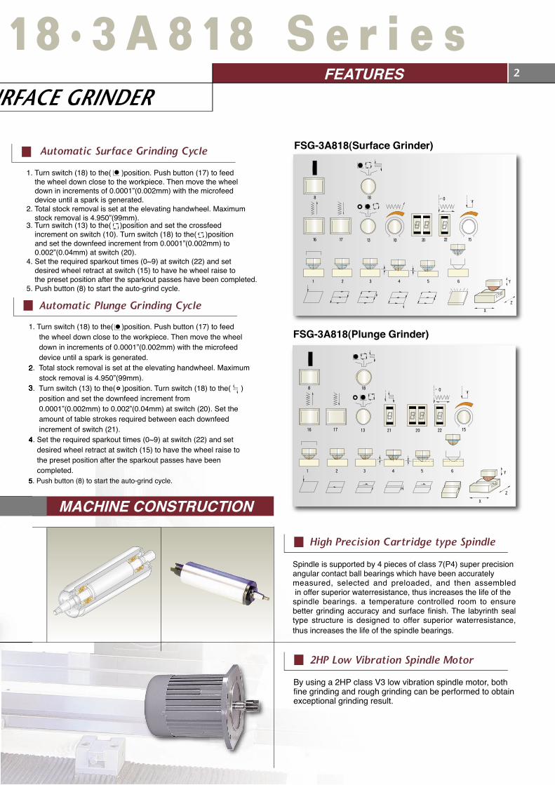
1. Turn switch (18) to the( )position. Push button (17) to feed the wheel down close to the workpiece. Then move the wheel down in increments of 0.0001”(0.002mm) with the microfeed device until a spark is generated.2. Total stock removal is set at the elevating handwheel. Maximum stock removal is 4.950”(99mm).3. Turn switch (13) to the( )position and set the crossfeed increment on switch (10). Turn switch (18) to the( )position and set the downfeed increment from 0.0001”(0.002mm) to 0.002”(0.04mm) at switch (20).4. Set the required sparkout times (0~9) at switch (22) and set desired wheel retract at switch (15) to have he wheel raise to the preset position after the sparkout passes have been completed.5. Push button (8) to start the auto-grind cycle.
111
1. Turn switch (18) to the( )position. Push button (17) to feed the wheel down close to the workpiece. Then move the wheel down in increments of 0.0001”(0.002mm) with the microfeed device until a spark is generated.2. Total stock removal is set at the elevating handwheel. Maximum stock removal is 4.950”(99mm).3. Turn switch (13) to the(
Y
Z
X
1 2 3 4 5 6
16 17 13 10 20 22 15
1880
)position. Turn switch (18) to the( ) position and set the downfeed increment from 0.0001”(0.002mm) to 0.002”(0.04mm) at switch (20). Set the amount of table strokes required between each downfeed increment of switch (21).4. Set the required sparkout times (0~9) at switch (22) and set desired wheel retract at switch (15) to have the wheel raise to the preset position after the sparkout passes have been completed.5. Push button (8) to start the auto-grind cycle.
Spindle is supported by 4 pieces of class 7(P4) super precisionangular contact ball bearings which have been accuratelymeasured, selected and preloaded, and then assembled in offer superior waterresistance, thus increases the life of thespindle bearings. a temperature controlled room to ensure better grinding accuracy and surface finish. The labyrinth seal type structure is designed to offer superior waterresistance, thus increases the life of the spindle bearings.
FSG-3A818(Plunge Grinder)
FSG-3A818(Surface Grinder)
By using a 2HP class V3 low vibration spindle motor, both fine grinding and rough grinding can be performed to obtain exceptional grinding result.
MACHINE CONSTRUCTION
device until a spark is generated.2. Total stock removal is set at the elevating handwheel. Maximum stock removal is 4.950”(99mm).3. 0.0001”(0.002mm) to 0.002”(0.04mm) at switch (20). Set the amount of table strokes required between each downfeed increment of switch (21).4. Set the required sparkout times (0~9) at switch (22) and set desired wheel retract at switch (15) to have the wheel raise to the preset position after the sparkout passes have been completed.5. Push button (8) to start the auto-grind cycle.
Automatic Plunge Grinding Cycle
Automatic Surface Grinding Cycle
High Precision Cartridge type Spindle
2HP Low Vibration Spindle Motor
2FEATURES

F S G - 2 A 8HIGH PRECISION SS
By using proximity switches, the operator can easily set a suitable table stroke for each workpiece to save grinding time and obtain higher grinding efficiency. The proximity switches have been properly covered for operator safety.
The control station can be easily adjusted to a comfortable position for the operator’s convenience. All switches, indicators, lamps, LEDS, and displays are ergonomically designed for ease of operation.
3 MACHINE CONSTRUCTION
Table Reversing Mechanism
Control Station(FSG-3A818)
The table traverses on hardened and round guideways with accurately sieved steel ball bearings, p rov id ing smooth , accurate and efficient table movement.
Table Guideways
MACHINE BASE SLIDEWAYS ARE INATED WITH TURCITE-B AND PRECISELY HAND CRAPED. LOW FRICTION SLIDWAYS
DURABLE SLIDEWAYS
The elevating system is equipped with a precision 0.0001” graduated micro feed device, consisting of a worm and wormgear for precise manual positioning of the corss axis.
Elevating Micro Feed Device (FSG-3A818)
INCORPORATED WITH AN AUTOMATIC INTERMITTENT
L U B R I C AT I O N S Y S T E M ENSURE HIGH ACCURACY AND LONGER WAY LIFE.

1 8 • 3 A 8 1 8 S e r i e sSURFACE GRINDER
INSPECTION 4
Due to excellent rigidity and stability of machine structure, the flatness tolerance of ground workpieces shall be 0.00012"(0.003mm) or better.
Attach the base of a test indicator to the wheel head. Touch the stylus of the indicator to the table surface.Traverse the table in and out, The indicator variation shall be within 0.00008"(0.002mm).
Attache the base of test indicator the the wheel head. Touch the stylus of the indicator to the table surface.Move the table left to right and reverse. The indicator variation shall be within 0.0001"(0.0025mm).
Apply a test indicator to the rear,middle and front points of conicalsurface of the wheel spindle, androtate the wheel spindle, the variation shall be under 0.00006"(0.0015mm).
Before delivery, the spindle of each machine has to be calibrated by a portable precision dynamic vibration measuring equipment. The final amplitude of spindle vibration shall be under 0.0012"/s(0.03mm/s)
Steel balls used in longitudinalmovement are all heat treated andsieved by automatic machine whichassures the diameter tolerance ofsteel balls in the same machine isunder 0.00008"(0.002mm)
Attach the base of a test indicator to the wheel head. Touch the stylus of the indicator to the table surface. Traverse the table in and out. The indicator variation shall be within 0.00016"(0.004mm).
Steel Ball Sifting
Parallelism of Table Surface toTable Cross Transverse
Runout of Wheel SpindleConical Surface
Parallelism of Table Surface toTable Longitudinal Movement Spindle Dynamic Balancing Test
Parallelism and Squareness of Wheel Spindle Centerline to Table Surface
Flatness of Ground Workpiece
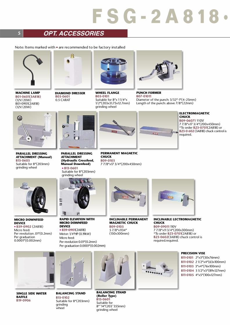
MACHINE LAMPB01-0601(3A818)(12V/20W)B01-0901(2A818)(12V/20W)
DIAMOND DRESSER WHEEL FLANGEB05-0101 Suitable for 8”x 1 1/4”x1/2”(203x31.75x12.7mm) grinding wheel
PUNCH FORMERB07-01011 Diameter of the punch: 3/32”-1”(4~25mm)Length of the punch: above 7/8”(22mm)
PARALLEL DRESSINGATTACHMENT (Manual)B13-0603Suitable for 8”(203mm) grinding wheel
PERMANENT MAGNETIC CHUCKB09-0103 7 7/8”x17 3/4”(200x450mm)
ELECTROMAGNETICCHUCKB09-06071 110V7 7/8”x17 3/4”(200x450mm)*To order B23-0701(2A818) orB23-0 602 (3A818) chuck control isrequired.
INCLINABLE PERMANENT MAGNETIC CHUCKB09-01055 7/8”x1134”(150x300mm)
INCLINABLE LECTROMAGNETICCHUCKB09-09011 110V7 7/8”x11 3/4”(200x300mm)*To order B23-0701(2A818) orB23-0602(3A818) chuck control is required.required.
BALANCING STANDB15-0102 Suitable for 8”(203mm) grindingwheel
BALANCING STAND(Roller Type)B15-0601Suitable for 8”~14”(203~355mm)grinding wheel
PRECISION VISEB11-0101 2”x3”(50x76mm)B11-0102 2 1/2”x4”(63x100mm)B11-0103 3”x4”(76x100mm)B11-0104 3 1/2”x5”(89x127mm)B11-0105 4”x5”(100x127mm)
SINGLE SIDE WATERBAFFLEB19-0906
RAPID ELEVATION WITHMICRO DOWNFEEDDEVICE• B39-0901(2A818)Motor: 1/4”HP (0.19kW)Micro feed:Per revolution 0.01”(0.2mm)Per graduation 0.0001”(0.002mm)
PARALLEL DRESSINGATTACHMENT(Hydraulic Crossfeed,Manual Downfeed) • B13-0601 Suitable for 8”(203mm) grinding wheel
MICRO DOWNFEEDDEVICE• B39-0902 (2A818)Micro feed:Per revolution .01”(0.2mm)Per graduation 0.0001”(0.002mm)
5 OPT. ACCESSORIES
Note: ltems marked with • are recommended to be factory installed
F S G - 2 A 8 1 8 •
B03-06010.5 CARAT

COOLANT SYSTEM WITHMANUAL PAPER FEEDINGDEVICE (With 1 Roll of Paper)B17-0107Volume: 85L,Pump: 1/8HPCoolant Capacity: 20L/minSpace: 21 21/32”x39 3/8”(550x1000mm)Height: 30 1/2”(775mm)
DUST COLLECTORB17-0102Suction Motor: 1/2HP, 2PSpace: 18 1/2”x19 11/16”(470x500mm)Height: 23”(585mm)
COOLANT SYSTEMB17-0110Volume: 42L, Pump:1/8HPCoolant Capacity: 20L/minSpace: 21”x14 1/4”(530x360mm)Height: 19 7/8”(500mm)
SPLASH GUARD WITHNOZZLE FOR COOLANTSYSTEMB19-0909
UNIVERSAL WHEEL GUARD OR SIDE FORMINGB41-0901Suitable for: 8”(203mm) grinding wheel
COMBINATION COOLANT &DUST EXHAUST UNITB17-0101Volume: 34L, Pump: 1/8HPCoolant Capacity: 20L/minSpace: 15 3/4”x31 1/16”(398x798mm)Height: 26 3/4”(680mm)
COOLANT SYSTEM WITHMAGNETIC SEPARATORB17-0105Volume: 50L, Pump: 1/8HPCoolant Capacity: 20L/minSeparator Capacity: 20L/minSpace: 25 3/4”x20 1/2”(655x520mm)Height: 28 3/4”(730mm)
CHUCK CONTROLLER• B23-0701 (2A818)Input: 140V ACOutput: 115V DCWith variable holding power control and auto.demagnetizer.
COOLANT SYSTEM WITHFILTERB17-0901Volume: 95L,Pump: 1/8HPCoolant Capacity:20L/minSpace: 26”x19”(660x480mm)Height: 24”(610mm)
COMBINATION COOLANT &DUST EXHAUST UNIT WITHMAGNETIC SEPARATORB17-0106Volume: 34L, Pump:1/8HPCoolant Capacity: 20L/minSuction Motor: 1/2HPSeparator Capacity: 20L/minSpace: 24 3/4”x31 1/16”(628x790mm)Height: 26 3/4”(680mm)
CHUCK CONTROLLER• B23-0602 (3A818)Input Voltage: 135V ACOutput Voltage: 110V DCWith variable holding power control and auto.demagnetizer.
6 OPT. ACCESSORIES
3 A 8 1 8 S e r i e s
STD. ACCESSORIES
1. Pin spanner wrench 2. Wrench 3. Dust rotection plate 4. Tool box 5. Hex. wrenches 6.Touch-up paint 7. Levelling pad 8. Levelling set screw 9. Small plug10. Fuse11. Balancing arbor12. Wheel flange extractor 13. Big plug14. Magnetic chuck setting screw15. Lifting rods

C
at.:
0916
-000
03C
00 /
R00
0048
153
/ 200
5050
4 / 1
000
D
TP D
esig
n: V
IVI /
FAL
CO
N M
ACH
INE
TOO
LS C
O.,
LTD
.
MODEL 818 Series
A lbs(kg) 474(215)
B lbs(kg) 77(35)
C lbs(kg) 551(250)
Description FSG-2A818/3A818Table size 8”x18”(203x457mm)Max. grinding length Longitudinal 18”(457mm)Max. grinding width Crosswise 8”(203mm)Max. Distance from Table Surface to Spindle Centerline 18”(457mm)
Standard Magnetic Chuck Size 7 7/8”x17 3/4”(200x450mm)
LongitudinalMovement of Table
Travel, hydraulic 19 3/4”(500mm) Maximum travel, manual 21”(530mm) Table speed, variable 16~82 fpm(5~25m/min)
Cross transverseTravel
Rapid travel, approx. 48 imp(960mm/min) Auto increment. 0.02~0.24”(0.4~6mm) Max. auto travel 9”(230mm) Max. manual travel 9 1/2”(240mm) Handwheel per revolution 0.2”(4mm) Handwheel per graduaion 0.001”(0.02m)
WheelheadVerticalInfeed
Automatic infeed (3A only) 0.0001”~0.002” (0.002~0.04mm) Handwheel per revolution 0.1”(2mm) Handwheel per graduation 0.0005”(0.01mm) Rapid travel, approx. (3A only)13 imp(330mm/min) Micro Per revolution (3A only)0.01”(0.2mm) feed Per graduation (3A only)0.0001”(0.002mm)
Grinding SpindleDrive
Speed 60Hz / 3450 rpm, 50Hz / 2850 rpm Power rating 2HP/1.5kW
Hydraulic Drive Standard accessory 1HP/0.75kWCrossfeed Drive Standard accessory 0.05HP/40WElevating Drive Standard accessory (3A only)1/4HP/0.19kW
Standard Grindingwheel
Diameter 8”(203mm) Width 1/2”(12.7mm) Bore 1 1/4”(31.75mm)
Floor Space (LxWxH) 90”x62”x68”(2300x1575x1740mm)
Net Weight approx. Based on 2A 2620 lbs(1190kg)
Rated Power 5HP/3.7kW
Packing Dimensions (LxWxH) 73”x61”x87”(1854x1549x2210mm)
A
B
E
FG
IH
D
LKJ
C
PERMISSIBLE LOADS OF MACHINE
Grinding with Electromagnetic Chuck
Grinding without Electromagnetic Chuck
A=Workpiece B=Magnetic Chuck C=A+B
The total suggested maximum loads of working table are shown as follows:
DIMENSIONAL DRAWINGS
MODEL 2A818 3A818
A 85 7/8"(2180mm) B 27 1/8"(690mm)
C 68"(1740mm) 47 1/2"(1900mm)
D 1/2" (12.7mm)
E 12" (305mm)
F 15/32"(12mm)
No. 34, Hsing Kong Road, Shang Kang, Chang HuaTAIWAN 509TEL: 886-4-7991126 FAX: 886-4-7980011http://www.chevalier.com.twE-mail: [email protected] Factory TEL:886-4-25673266
U.S.A. OFFICE
9925 Tabor Place Santa Fe Springs, CA 90670 U.S.ATEL:(562)903-1929FAX:(562)903-3959
Manual rinders CNC Profile Grinders Automatic Grinders Molecular ecompositionProcess (MDP) Grinder VMC (Various Sizes) VMC w. turntable Slant Bad CNC Lathes Teach-in Lathes
MODEL 2A/3A818 G 8 1/8"(206mm) H 10 3/4"(274mm)
I 10 5/8"(271mm)
J 18" (457mm)
K 8" (203mm)
L 2 1/8"(54mm)
※ Note: The manufacturer reserves the right to modify the design, specifications, mechanisms... etc. of the machine without prior notice.All the specifications shown above are just for reference.
SPECIFICATION
approx.