high temperature leakage performance of a hybrid brush seal
TRANSCRIPT

HIGH TEMPERATURE LEAKAGE PERFORMANCE OF A
HYBRID BRUSH SEAL COMPARED TO A STANDARD BRUSH
SEAL AND A LABYRINTH SEAL
A Thesis
by
ZACHARY SPENCER ASHTON
Submitted to the Office of Graduate Studies of Texas A&M University
in partial fulfillment of the requirements for the degree of
MASTER OF SCIENCE
August 2009
Major Subject: Mechanical Engineering
ii
HIGH TEMPERATURE LEAKAGE PERFORMANCE OF A
HYBRID BRUSH SEAL COMPARED TO A STANDARD BRUSH
SEAL AND A LABYRINTH SEAL
A Thesis
by
ZACHARY SPENCER ASHTON
Submitted to the Office of Graduate Studies of Texas A&M University
in partial fulfillment of the requirements for the degree of
MASTER OF SCIENCE
Approved by:
Chair of Committee, Luis San Andrés Committee Members, Alan Palazzolo
Peter Keating Head of Department, Dennis L. O’Neal
August 2009
Major Subject: Mechanical Engineering

iii
ABSTRACT
High Temperature Leakage Performance of a Hybrid Brush Seal Compared to a
Standard Brush Seal and a Labyrinth Seal. (August 2009)
Zachary Spencer Ashton, B.S., Clemson University
Chair of Advisory Committee: Dr. Luis San Andrés
Adequate sealing in turbomachinery reduces secondary leakage and results in more
efficient and stable systems. Labyrinth seals are most common, although brush seals are
popular in specialized applications. The Hybrid Brush Seal (HBS) is a novel design that
adds to the bristle brush matrix a number of cantilever pads that rest on the rotor surface.
Upon shaft rotation the pads lift due to the generation of a hydrodynamic gas film while
the brushes effectively seal an upstream pressure. Hence the HBS has no wear and no
local thermal distortion effects.
Measurements of leakage versus pressure differential are obtained in a three-teeth
labyrinth, a conventional brush seal, and a hybrid brush seal for operation at high
temperature (300ºC), with shaft surface speeds to 27 m/s, and at supply pressures to 3.5
bar. Flow measurements are presented in terms of a flow factor to remove dependency
on the air temperature and supply pressure. The measurements demonstrate the HBS
leaks less (~61%) than a standard brush seal and is significantly better (~38%) than a
similarly sized labyrinth seal. Predictions of flow through a labyrinth seal predict well at
supply pressures under 1.7 bar but overpredict by as much as 25% at high supply
pressures. A porous medium fluid flow model predicts the flow through the HBS and
brush seal. The model for the HBS and brush seal underpredicts the flow rate at low
supply pressures but match well at high supply pressures.

iv
Measurements of the drag torque of the test seals show the HBS has a larger torque
when pressurized compared to the brush seal and labyrinth seal. This indicates that the
HBS experiences a larger degree of blow-down due to the pads decreasing the clearance.
The mechanical parameters of the brush seal and HBS are found based upon the
flexibility function from impact load tests. A combined structural and dry friction
damping model represent well the measured flexibility. An equivalent damping is found
based upon the energy dissipation. Based upon the damping ratio, the HBS has twice of
the viscous damping as the brush seal at a supply pressure of 2.0 bar.

v
DEDICATION
To my wife, Anna, for her covenantal love and support through all times. I am so
blessed to have you by my side. To my son, Owen, for the joy he has brought to our
lives. To my parents, Mark and Cathy, for their continual love and guidance.

vi
ACKNOWLEDGEMENTS
Thanks to Dr. Luis San Andrés, my advisor and committee chair, for providing the
opportunity to research the problem presented. His technical guidance and support have
been invaluable for the duration of this research.
Thanks to Dr. Adolfo Delgado for educating me in the details of the test rig and of
the previously work done on Hybrid Brush Seals. His experience at the Texas A&M
University Turbomachinery Laboratory provided a strong foundation upon which to
build the body of research. Additionally, thanks to the other students at the
Turbomachinery Lab who have provided help along the way.
Thanks to Brian Butler for the excellent work in the construction of a wide range of
components for the test rig. His knowledge and expertise have been essential in the
creation of the high temperature rig.
Thanks to the sponsor, Siemens Power Generation, for providing financial support
for the duration of the project and to John Justak of Advanced Technology Group, Inc.
for providing the test brush seal and HBS.

vii
NOMENCLATURE A πDCr . Flow area in non-contacting clearance seal [m2]
Ceq System equivalent damping [N-s/m]
Cr IDs - ODd. Seal radial Clearance [m]
D ODd . Rotor diameter [m]
F Input force to system [N]
I Shaft and disc area moment of inertia [m4]
IDh Air cylinder housing inner diameter [m]
IDs Seal ring inner diameter [m]
IF Interference fit between housing and seal [m]
kV V/ω. Motor constant [V.sec/rad]
Keq System equivalent stiffness [N/m]
l Seal axial length [m]
L Shaft length [m]
Le Location of displacement measurements and impact load [m]
Ls Location of test seal [m]
m Mass flow rate [kg/s]
Md Mass of disc [kg]
Meq System equivalent mass [kg]
NT Number of teeth in labyrinth seal
ODs Seal ring outer diameter [m]
ODd Disc outer diameter [m]
P Gas (absolute) pressure in seal [Pa]
Pe Absolute exhaust pressure [Pa]
Ps Absolute supply pressure [Pa]
Pr Pressure ratio (Ps/Pe)
V i . Motor power (voltage x current) [W]

viii
g Gas constant [J/kg-K]
X Displacement response of disc at sensor location [m]
T Gas temperature [K]
Torque
. Motor Torque [N.m]
b Bristle material thermal expansion coefficient [13.5*10-6 /ºC]
d Disc material thermal expansion coefficient [11.2*10-6 /ºC]
h Cylinder housing material thermal expansion coefficient [12*10-6 /ºC]
s Seal ring material thermal expansion coefficient
Labyrinth seal: [23.6*10-6 /ºC]
Brush seal and HBS: [12*10-6 /ºC]
ρ Shaft and disc density [kg/ m3]
γeq Equivalent structural damping
µ Dry friction damping
i Flow coefficient
0 Kinetic-energy carryover factor
Bristle lay angle [degrees]
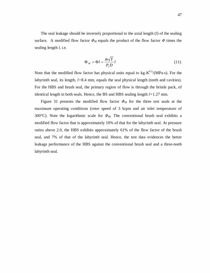
Φ
DPTm
s
Flow factor [kg- K0.5/(MPa-m-s)]
Shape function for cantilevered beam
Φ M s
ml TP D
Modified flow factor [kg-K0.5/(MPa-s)]
ω Shaft angular speed [rad/s]
n System natural frequency [rad/s]
eqeq
eq
MKC
2Viscous damping ratio

ix
TABLE OF CONTENTS
Page
ABSTRACT .................................................................................................................. iii
DEDICATION................................................................................................................ v
ACKNOWLEDGEMENTS ........................................................................................... vi
NOMENCLATURE ..................................................................................................... vii
TABLE OF CONTENTS............................................................................................... ix
LIST OF FIGURES ...................................................................................................... xii
LIST OF TABLES....................................................................................................... xvi
CHAPTER
I INTRODUCTION.................................................................................... 1
II LITERATURE REVIEW......................................................................... 4
Seals for Gas Turbines ....................................................................... 4 Labyrinth Seals .................................................................................. 5 Brush Seals ........................................................................................ 7 Hybrid Brush Seals ............................................................................ 9
III HIGH TEMPERATURE TEST APPARATUS ...................................... 12
Seal Test Rig.................................................................................... 12 Test Seals......................................................................................... 17
IV LEAKAGE MEASUREMENT IN A THREE-TEETH LABYRINTH
SEAL..................................................................................................... 20
Experimental Procedure ................................................................... 20 Results and Discussion..................................................................... 21

x
CHAPTER Page
V MEASUREMENTS OF CLEARANCE AND LEAKAGE
PREDICTIONS FOR A TEST THREE-TEETH LABYRINTH
SEAL..................................................................................................... 25
Experimental Procedure ................................................................... 25 Results and Discussion..................................................................... 27
VI LEAKAGE MEASUREMENT IN A CONVENTIONAL BRUSH
SEAL..................................................................................................... 36
Experimental Procedure ................................................................... 36 Results and Discussion..................................................................... 37
VII LEAKAGE MEASUREMENTS IN A HYBRID BRUSH SEAL ........... 41
Experimental Procedure ................................................................... 41 Results and Discussion..................................................................... 41
VIII COMPARISON OF LEAKAGE FOR THREE TEST SEALS ............... 46
IX SEALS DRAG TORQUE AT AMBIENT TEMPERATURE ................ 50
Experimental Procedure ................................................................... 50 Results and Discussion..................................................................... 51
X IDENTIFICATION OF SEAL EQUIVALENT MECHANICAL
PARAMETERS FROM IMPACT LOAD TESTS ................................. 55
Experimental Procedure ................................................................... 55 Results and Discussion..................................................................... 59
XI CONCLUSIONS AND RECOMMENDATIONS.................................. 64
REFERENCES ............................................................................................................. 67

xi
Page
APPENDIX A: CALIBRATION OF FLOW METER FOR OPERATION AT A
RANGE OF PRESSURES AND TEMPERATURES.......................... 70
APPENDIX B: CALIBRATION OF PRESSURE SENSOR......................................... 72
APPENDIX C: USER INTERFACE FOR DATA ACQUISITION AND
CONTROL ......................................................................................... 74
APPENDIX D: CALIBRATION OF HIGH TEMPERATURE OPTICAL
SENSORS .......................................................................................... 76
APPENDIX E: ROTOR WEAR DUE TO SEAL CONTACT....................................... 77
VITA................................................................................................................................. 79

xii
LIST OF FIGURES
Page
Figure 1: View of downstream (left) and inside view of teeth (right) of a three-teeth
labyrinth seal. ............................................................................................... 5
Figure 2: Upstream (left) and downstream (right) view of a conventional brush seal
with brushes on the upstream and the backing plate on the downstream
side............................................................................................................... 7
Figure 3: Upstream (left) and downstream (right) view of a HBS with brushes on
the upstream and the cantilever pads on the downstream side...................... 10
Figure 4: High temperature seal test rig with major components................................. 12
Figure 5: Cutaway view of the pressurization cylinder with instrumentation. ............. 14
Figure 6: Cutaway view of the shaft support with tapered roller bearings. .................. 15
Figure 7: Cutaway view on disc centering system with fiber optic displacement
sensors........................................................................................................ 16
Figure 8: Soft mounted shaker connecting to shaft via load cell and stinger................ 17
Figure 9: Dimensions of three-teeth labyrinth seal for leakage measurements............. 20
Figure 10: Mass flow rate for three-teeth labyrinth versus pressure ratio for various
inlet gas temperatures (30-300ºC). Rotor speed at 3,000 RPM. ................... 22
Figure 11: Flow factor Φ for three-teeth labyrinth seal versus pressure ratio
(supply/exhaust) for varying inlet temperatures (30-300ºC). Rotor speed
at 3,000 RPM. ............................................................................................ 23
Figure 12: Mass flow rate for three-teeth labyrinth seal versus rotor speed at three
pressure ratios (PR=Ps/Pe=1.2,2.0,2.8). Air inlet temperature of 300ºC ....... 24
Figure 13: Seal centering device and optical sensors for measuring gap in
horizontal and vertical directions. ............................................................... 26
Figure 14: Location of thermocouples viewed from the downstream end (low
pressure side) with exhaust duct removed. Thermocouple on housing is
located on the outer surface of housing (exposed to ambient air)................. 27

xiii
Page
Figure 15: Temporal evolution of temperatures at various locations in test rig for
three-teeth labyrinth seal. Constant air flow at 35 g/s. Air inlet
temperature vs. time specified..................................................................... 28
Figure 16: Temporal evolution of diametral clearance and air inlet temperature
(nominal clearance of 1.04 mm at room temperature) in three-teeth
labyrinth seal. Operation with constant flow at 35 g/s. No shaft rotation. ... 29
Figure 17: Temporal evolution of supply pressure and air inlet temperature and in
three-teeth labyrinth seal. Operation with constant flow at 35 g/s................ 29
Figure 18: Three-teeth labyrinth seal diametral clearance using feeler gauges and
predictions versus gas inlet temperature. No shaft rotation. ......................... 31
Figure 19: Predicted mass flow rate versus (inlet/exhaust) pressure ratio for
three-teeth labyrinth seal using model and XLLaby©. No shaft rotation.
Predictions based on measured clearance at 30ºC and 300ºC (0.52 mm). .... 33
Figure 20: Predicted and measured mass flow rate versus (inlet/exhaust) pressure
ratio for three-teeth labyrinth seal at two inlet temperatures. No shaft
rotation. Predictions based on two distinct (measured) clearances. .............. 34
Figure 21: Predicted and experimental flow factor Ф versus (inlet/exhaust) pressure
ratio for three-teeth labyrinth seal at two inlet temperatures. No shaft
rotation. Predictions based on two distinct clearances. ................................ 35
Figure 22: Mass flow rate for conventional brush seal versus pressure ratio
(supply/exhaust) for varying inlet temperatures (30-300ºC). Rotor Speed
at 3,000 RPM. ............................................................................................ 37
Figure 23: Flow factor Φ for conventional brush seal versus pressure ratio
(supply/exhaust) for varying inlet temperatures (30-300ºC). Rotor speed
of 3,000 RPM. ............................................................................................ 38
Figure 24: Mass flow rate for conventional brush seal versus rotor speed at three
pressure ratios (PR=Ps/Pe=1.3,1.7,3.0). Air inlet temperature of 300ºC ....... 39

xiv
Page
Figure 25: Comparison of predicted and measured mass flow rates in brush seal
versus pressure ratio [Ps/Pe]. Rotor speed of 3000 RPM. Air inlet
temperature at 300ºC. Predictions from model in [25]................................. 40
Figure 26: Mass flow rate for HBS versus pressure ratio (supply/exhaust) for
varying inlet temperatures (30-300ºC). Rotor speed at 3,000 RPM.............. 42
Figure 27: Flow factor Φ for HBS versus pressure ratio (supply/exhaust) for
varying inlet temperatures (30-300ºC). Rotor speed of 3,000 RPM. ............ 43
Figure 28: Mass flow rate for HBS versus rotor speed at three pressure ratios
(PR=Ps/Pe=1.5,2.5,3.6). Air inlet temperature of 300ºC .............................. 44
Figure 29: Comparison of predicted and measured mass flow rate in HBS versus
pressure ratio [Ps/Pe]. Rotor speed of 1000 RPM. Air inlet temperature
at 300ºC...................................................................................................... 45
Figure 30: Flow factor Φ for three test seals versus pressure ratio [Ps/Pe]. Air inlet
temperature at 300°C. Rotor speed at 3,000 RPM. ...................................... 46
Figure 31: Modified flow factor ΦM for three seal types versus pressure ratio
[Ps/Pe]. Air inlet temperature at 300°C. Rotor speed at 3,000 RPM............. 48
Figure 32: Mass flow rate versus pressure ratio [Ps/Pe] for current HBS and
previous HBS (Ref [22]). Air inlet temperature at 30°C. Rotor speed at
1,000 RPM and 600 RPM for the current HBS and previous HBS,
respectively. ............................................................................................... 49
Figure 33: Baseline motor power versus rotor speed. No gas pressurization. ............... 51
Figure 34: Baseline motor voltage and drag torque versus rotor speed. No gas
pressurization. Ambient temperature. Motor speed constant
kVω=V/ω = 0.24 V-s/rad (0.025 V/rpm). ...................................................... 52
Figure 35: Motor torque versus rotor speed for three seals with supply pressure of
2 bar. Tests without pressures (no leakage) also shown. Operation at
ambient temperature (25ºC). ....................................................................... 53

xv
Page
Figure 36: Torque versus rotor speed for current HBS and other HBS operating at
inlet pressure up to 2.0 bar and 1.7 bar, respectively. Operation at
ambient temperature (25ºC). ....................................................................... 54
Figure 37: First mode shape of test rotor and element model with structural and
support elements......................................................................................... 56
Figure 38: Schematic view of shaft-disc and seal assembly and its equivalent
representation as a single degree of freedom mechanical system................. 57
Figure 39: Amplitude of flexibility function for test rotor and hybrid brush seal
(HBS). Tests with air at supply pressure/exhaust pressure (PR)=1.5 and
2.0. Baseline (no seal) and with seal and no pressurization (PR=1.0)
included. Impact load tests. No shaft rotation. Ambient
temperature=25ºC....................................................................................... 59
Figure 40: Amplitude of flexibility function for test rotor and brush seal. Tests with
air at supply pressure/exhaust pressure (PR)=1.5 and 2.0. Baseline (no
seal) and with seal and no pressurization (PR=1.0) included. Impact load
tests. No shaft rotation. Ambient temperature=25°C ................................... 60
Figure 41: Measured flexibility in HBS and physical models with (a) structural
damping-dry friction and (b) viscous damping. Supply pressure ~ 2.0 bar.
Ambient temperature, no shaft rotation. ...................................................... 62
Figure 42: Measured flexibility in brush seal and physical models with (a) structural
damping-dry friction and (b) viscous damping. Supply pressure ~ 2.0 bar.
Ambient temperature, no shaft rotation. ...................................................... 62
Figure 43: Measured flexibility of test system without a seal in place and physical
models with (a) structural damping-dry friction and (b) viscous damping.
Ambient temperature, no shaft rotation, no pressurization........................... 63

xvi
LIST OF TABLES
Page
Table 1: Test seals-geometry and material properties .................................................. 19
Table 2: Pressurized cylinder air temperature and shaft speed for labyrinth seal
leakage tests .................................................................................................. 21
Table 3: Uncertainty for pressure ratio and mass flow rate in labyrinth seal................. 22
Table 4: Uncertainty for pressure ratio and mass flow rate in conventional brush
seal................................................................................................................ 38
Table 5: Uncertainty for pressure ratio and mass flow rate in conventional brush
seal................................................................................................................ 42
Table 6: Equivalent system coefficients with HBS and brush seal at three supply
pressures. Air inlet at 25°C. No shaft rotation. ............................................... 61

1
CHAPTER I
INTRODUCTION
Seals in turbomachinery affect both the efficiency, through leakage control, and the
rotordynamic stability of the entire system [1]. Improving seal design is often the most
cost-effective way to increase performance by limiting secondary leakage [1]. As
efficiency and power output requirements for turbomachinery rise, higher temperatures,
pressures, and shaft speeds become prevalent. Seals must be able to restrict flow while
withstanding often inclement conditions.
Labyrinth seals are non-contacting elements that provide an inexpensive and simple
method of obstructing flow from a high pressure region to a low pressure region [2]. The
design of the labyrinth seal is fairly simple and can be made to accommodate a large
range of sizes and operating conditions. New developments in labyrinth seals have
increased efficiency and decreased the likelihood of unstable rotor-bearing system
operation. The labyrinth seal, however, still allows a relatively large amount of leakage
because of its inherent clearance between the seal and rotor. A clearance must always be
present during long-term labyrinth seal operation. Clearances are enlarged due to
intermittent contact and wear at start-up and shutdown. The design of the labyrinth seals
in high temperature environments must include considerations for the thermal expansion
of the seal and rotor as well as considerations for windage heating. In certain instances,
long labyrinth seals may lead to rotordynamic instability due to swirling shear induced
flow in the circumferential direction [1].
In some industrial applications [3], brush seals replace labyrinth seals at the locations
of secondary leakage. The brush seal can exhibit leakage as low as 10% that of a
similarly sized labyrinth seal and will not excite a rotordynamic instability [3]. The
decrease in leakage renders higher engine efficiency in two ways. The brush seal allows
This thesis follows the style of the ASME Journal of Tribology.

2
less pressurized gas to escape and permits the rotor length and weight to decrease. In
addition to the benefit of less leakage, the brush seal can handle rotor radial movement
due to the soft structural stiffness of its bristles. The bristles are known to blow-down
during operation. Blow-down is described as the bristles moving radially towards the
rotor. This effect can aid to further decrease leakage. However, the brush seal best limits
leakage when in contact with its rotating disc. Contact leads to an increase in drag torque
and localized heat generation. Most brush seals are designed to rub until the proper level
of interference is reached. Therefore, certain design tradeoffs exist to minimize leakage
while preventing thermal instability of a brush seal due to excessive contact [4]. The
brush seal also only allows rotation in one direction due to the lay angle of the bristles.
Any degree of rotation in the opposing direction will often cause the bristles to buckle
and deform. Further, brush seals suffer from poor axial stiffness as the bristles tend to
bend in the direction of the pressure drop. This axial bending is controlled by the length
the bristles extend past the backing support plate. If the bristles are too long, and the
bending is excessive; the bristle tips may disconnect from the disc and allow a large
amount of leakage.
The Hybrid Brush Seal (HBS) seeks to improve engine performance and reliability
in comparison to labyrinth seals and brush seals. The HBS incorporates to the bristle
matrix of a brush seal a number of cantilever pads that initially rest on the rotor surface
when the rotor is not spinning [5]. HBSs have shown potential to decrease secondary
leakage by greater amounts than a shoed brush seals [6]. The design permits radial
movement of the rotor similar to a brush seal but with the added benefit of a high degree
of seal axial stiffness. This increase in axial stiffness should allow the HBS to operate at
higher pressure differentials. The HBS is designed to limited heat generation since the
pads experience a hydrodynamic lift from a thin air film during operation [5]. Further,
the HBS allows the benefit of rotor rotation in both directions. Due to the initial contact,
however, the HBS has high levels of drag torque during unpressurized conditions such
as those experienced during machine start-up [6].

3
For this novel technology to continue its advancement, its leakage, drag torque, wear
rate, and vibration characteristics must be quantified for a range of operating
temperatures, pressure differentials, and rotational speeds. The performance of the HBS
can then be directly compared to the performance of labyrinth seals and brush seals at
similar conditions. Direct comparisons of performance may provide the necessary
motivation for OEMs to consider updating existing seals. Furthermore, when introducing
a new component into a rotating machine, it is critical to quantify its impact on the
behavior and life of the overall system.

4
CHAPTER II
LITERATURE REVIEW Seals for Gas Turbines
This literature review discusses the general requirements for secondary seals in
turbomachinery. The review also reports on the previous research, detailing the
advantages and disadvantages, of two well established seals: labyrinth and brush.
Additionally, discussion is given to previous research on the Hybrid Brush Seal (HBS)
and its demonstrated potential to provide effective sealing at ambient temperature
conditions with reduced wear and increased radial stiffness. The previous research
serves as the basis for the high temperature measurements and predictions which follow
the literature review.
Chupp et al. [1] provide a comprehensive review of the uses and benefits of sealing
in turbomachinery. The review also discusses the location for seals and the benefits and
disadvantages for specific sealing methods. The seal types reviewed are for use in both
aero and land based gas turbines. During typical operation, interstage turbine seals may
experience temperatures up to 600ºC and absolute pressure differentials of 2.1 MPa [1].
Under these conditions growth of components and wear become increasingly important
to the life and performance of the seals. Over time, wear can drastically affect the
effectiveness of the seal and the overall efficiency of the turbomachine.
Floyd [2] discusses three main categories for rotary seals: clearance seals, contact
seals, and gas film seals. Contact and gas film seals provide the best leakage resistance
but are limited by the pressure differentials and surface speeds. As the pressure
differential and speed increase for contact seals, the rotating and stationary surfaces
begin to experience high levels of heating due to dry friction. This heating can lead to
thermal instabilities that could lead to high leakages at best, or complete machine failure
at worst. Therefore, careful design plays a critical role in all sealing methods, but
particularly in those which can come in contact with the rotating component. New

5
materials, coatings in particular, and novel designs for contact seals continue to expand
the boundary for acceptable operating conditions.
Labyrinth Seals Labyrinth seals represent the most prevalent means of reducing secondary leakage.
Labyrinth seals are clearance annular seals that operate with a gap between the stationary
and rotating component [1]. Figure 1 presents a basic three-teeth labyrinth seal. The
basic design of a labyrinth seal consists of a ring with multiple thin teeth spaced axially
running along the circumference of the seal ring [2]. The effectiveness of a labyrinth
seal is largely determined by the actual clearance between the tips of the teeth and the
opposing surface. Floyd [2] states that labyrinth seals typically have a radial clearance
(C) of 0.25-0.5 mm, while Childs [7] discusses cases with radial clearance to radius
ratios (C/R) of 0.0016-0.0076.
Demands for better performance led to design modifications such as steps,
honeycomb lands, and abradable contact surfaces [1]. The improvements allow for the
teeth to operate at a lower clearance with better wear characteristics in the case of radial
contact. The wear will eventually rub away the inner diameter of the seal until a
sufficient clearance develops. All of these designs, however, work on the basic principle
that a high pressure gas flow is retarded by the presence of a sharp-edged obstruction
which leads to a lower pressure in the succeeding cavity. Additional labyrinths can be
placed in parallel to add flow resistance thus decreasing further the leakage.
Figure 1: View of downstream (left) and inside view of teeth (right) of a three-teeth labyrinth seal.

6
Due to the simplicity of this design, labyrinth seals cost less to manufacture than
many other options and can be used over a wide range of operating temperatures, rotor
speeds, and pressures. Labyrinth seals can also be manufactured as rings or segmented
for easy installation, particularly for large land-based gas turbines. Floyd [1] states that
there are no limitations to the surface speed and pressure differential in which non-
contacting seals, such as the labyrinth seal, can withstand. El-Gamal et al. [8]
demonstrate theoretically that shaft speed has no affect on the leakage performance of
typical straight through labyrinth seals.
Design of labyrinth seals operating at high temperatures requires considerations for
the thermal growth of the seal and the rotor so that an allowable clearance is maintained
during normal operation. The radial clearance must also be large enough to permit the
radial excursions of the rotor for the particular operation and running speed at which it is
being used. The flow through the clearance can also introduce cross-coupled stiffness
due to circumferential swirl in the cavity, which may lead to rotor-bearing instability [9].
Childs et al. [10] effectively use swirl brakes to lower cross-coupled stiffnesses that lead
to rotordynamic instability.
Denecke et al. [11] show that a complex relationship exists between the heating of
the air traveling through a labyrinth seal and the development of circumferential swirl.
Choi et al. [12] show that small clearances and a large tooth pitch can reduce the seal
leakage. However, small clearances also lead to more windage heating and shorter part
life. The heating can lead to changes in clearance, higher operating torques, and even
shaft bowing. Further, hot air ingestion may prove harmful to the succeeding turbine
stages. Therefore, it is particularly important to understand the heating and rotordynamic
effects in axially long labyrinth seals, since these seals typically are most prone to
develop undesirable circumferential swirl flow.
Effective labyrinth seal designs often require multiple seals working in parallel to
step down from the supply pressure to the discharge pressure. This can result in multiple
sections of labyrinth seals over the course of a lengthy axial segment. As the axial

7
length of the shaft is increased, the shaft becomes heavier and the engine has a lower
efficiency. Additionally, the natural frequency of the system will decrease with a longer
rotor.
Brush Seals
Brush seals may increase engine efficiency by up to one-sixth (1/6) of a percentage
point [4]. The brush seal design consists of a bed of densely packed metallic or plastic
bristles attached to an outer ring. Figure 2 displays a typical brush seal from upstream
and downstream views. Common practice requires that the bristle tips contact the
rotating shaft during operation. If the bristles lose contact, performance will drastically
decrease. On the exhaust side of the seal, a back plate prevents the bristles from extreme
axial bending caused by the imposed pressure differential [3]. The bristles are set at a
specific lay angle, usually between 30° and 60°, in the direction of shaft rotation. The
rotor must rotate in the direction of the bristle lay angle; otherwise, the bristles will
buckle and distort causing higher levels of leakage [1].
Figure 2: Upstream (left) and downstream (right) view of a conventional brush seal with brushes on the upstream and the backing plate on the downstream side.
Ferguson reports the brush seals can result in as low as 10% of the leakage of a
similarly sized labyrinth seal [3]. Since the brush seal exhibits a lower leakage per axial
length, the rotor length and weight decrease. Ferguson [3] first discusses the
phenomenon of brush seal blow-down and the benefit on leakage performance. Blow-
down is described as the bristles of the seal moving in towards the rotor during

8
pressurized operation. This action serves to reduce leakage while increasing the drag
torque. Two main forces drive the phenomenon: axial compression of the bristle pack
and aerodynamic forces on the bristle tips. Crudgington and Bowher [13] discuss axial
compression due to the pressure differential as the source of blow down. The authors
[13] compare the level of blow-down using measurements of bristle movement and
Finite Element Analysis (FEA) model results and find that torque increases nearly
linearly as a function of interference and pressure drop. They also determine the
magnitude of clearance to estimate the blow-down for different pressure differences.
Crudgington and Bowher [13] find that the blow-down can be broken into two types of
regimes with respect to the pressure drop: a linear increase up to a pressure drop of 1
bar, followed by a constant level of blow-down for pressure differentials above 1 bar.
Franceschini et al. [14] study blow down due to aerodynamic forces on the bristles.
These forces create a moment on the bristle tip, pulling the bristles closer to the rotor.
As with the axial compression of the bristle pack, the aerodynamic forces increase at
higher pressure differentials.
Brush seals are known to not promote rotordynamic instability. Conner and Childs
[15] present rotordynamic measurements of a four-stage brush seal. Their results show
low and often times stabilizing cross-coupled stiffnesses. Chupp et al. [1] also note that,
because of their inherent compliance, brush seals are better suited to handle rotor
excursion during transient excursions. However, brush seal stiffening or bristle
hysteresis can sometimes occur due to excursions of the rotor into the bristles. Basu et
al. [16] describe the phenomenon in which the bristles fail to close onto the rotor after
some excursion, thus resulting in a significantly higher leakage and decreasing the
efficiency of the machine. Zhao and Stango [17] study the interbristle forces causing
brush seal hysteresis; finding that brush seals with the smallest lay angles are least likely
to experience hysteresis.
Brush seal design is critical to proper operation. Dinc et al. [18] outline the general
process to designing brush seals. Bristle length is one of the greatest design tradeoffs.
Short bristle packs can cause failure if radial excursions of the shaft cause contact with

9
the back plate. If the bristles are too long, on the other hand, the pressure differential
causes the bristles to buckle thus reducing the effectiveness of the seal to prevent
leakage [4]. Additionally, design considerations are involved with the level of contact
the bristles make with the rotating component. If the contact is too hard, the rub may
cause excessive frictional heating which causes thermal growth in the interference. This
leads to more friction and rotor growth until the seal fails. This represents a thermal
instability. Too little interference, however, may result in a higher mass flow rate,
negating the seal usefulness.
Proper brush seal operation also requires considerations for multiple frictional
interactions within the seal itself. Aksit [19] shows analysis of the stresses due to the
frictional interactions of brush seals. These interactions can be classed into three
categories: interbristle contact, bristle to back plate contact, and bristle to rotor contact.
Each of these factors can limit the life of the brush seal leading to unscheduled engine
maintenance, and even possible overhaul for seal replacement. Further, the friction in
brush seals may lead to high levels of drag torque during shaft rotation. Friction
between the bristles is also likely to cause high levels of hysteresis in brush seals.
Hybrid Brush Seals
The HBS is a novel design developed to further limit secondary leakage. Justak [5]
claims leakage equivalent to a similarly sized labyrinth seal at 0.038 mm radial
clearance. As with efficiency improvements from the labyrinth seal to brush seal, the
HBS results in more judicious usage of fuel and a lighter rotor. The HBS design
incorporates cantilevered pad elements to the bristle matrix. Wire EDM spring elements
connect the pads to the outer ring, and the bristle tips contact the outer surface of each
pad to prevent air passage through the seal. Figure 3 shows the seal with the bristle pack
on the front side and the cantilevered pads on the back side. During operation, the
arctuate pads result in the formation of a hydrodynamic film. The low radial stiffness of
the cantilever pads and bristles allows the pads to lift. The generation of a gas film

10
results in a relatively low level of leakage while preventing contact between the rotor
and seal.
Figure 3: Upstream (left) and downstream (right) view of a HBS with brushes on the upstream and the cantilever pads on the downstream side.
San Andrés et al. [6] experimentally find, that upon pressurization, the fluid film
greatly reduces the torque required to overcome any interference between the seal and
rotating component. This prevents thermal instability such as that in standard brush
seals. Further, the pads ability to move in the radial direction during operation means
the HBS does not require the precision manufacturing tolerances associated with
labyrinth seals [5]. The cantilever pad elements also add considerable axial stiffness to
the seal [6], thus allowing for operation at higher differentials than with standard brush
seals.
Rotordynamic tests in Ref. [20] show that the HBS does not excite rotordynamic
instability. Delgado and San Andrés [21] find that the bristle-to-bristle and bristle-
backplate contact found in both conventional brush seals and a shoed-brush seal
produces a stick-slip motion regime. A shoed-brush seal is similar to a HBS only without
the spring backing elements. By extension, it is expected that the HBS would experience
a similar stick-slip motion. Therefore, a certain load limit must be reached before the
excitation of the rotor occurs. Delgado and San Andrés [21] use a combined structural
damping and dry friction coefficient to model the mechanical energy dissipation of a
cantilever shaft system with a brush seal on the free end of the shaft. Baker [22] finds
the HBS dry friction is between 0.51-0.69 depending on the supply pressure imposed.

11
Additionally, some degree of viscous damping may be present as a result of the
generation of a hydrodynamic film under the pads [5].
Delgado et al. [20] predict the rotordynamic force coefficients for a shoed-brush seal.
They find that the seal coefficients are fairly independent of operating clearance and
supply pressure. Further, they show that the whirl frequency ratio (WFR) is much lower
than 0.50 for most rotor speeds. This implies stable operation well beyond twice the first
rotor-bearing system critical speed. Baker [22] extends rotordynamic measurements to
the HBS for operating at ambient temperature and shows predictions that closely match
the real equivalent stiffness and damping.
It is imperative to continue the evaluation of the performance and stability of the
sealing methods. By increasing temperature, supply pressure, and rotational speed, the
test conditions are able to better match those of a typical gas turbine.

12
CHAPTER III
HIGH TEMPERATURE TEST APPARATUS Seal Test Rig
Figure 4 displays the high temperature annular seal test rig with its major
components labeled. The test rig contains a pressurization cylinder. In the front side of
the cylinder, a disc connected to a shaft rests within a test seal. On the other side, a quill
shaft passes through the chamber to a DC motor (90 V, 9.4 A) via a flexible coupling.
Figure 4: High temperature seal test rig with major components.
Pressurized air (max ~8.6 bar) passes through a particle and coalescing filter to
remove any water or oil in the air. The supplied air then travels past a flow meter that
records the volumetric flow rate. The air pressure is measured immediately afterward.
With this information, the volumetric flow rate for a specific pressure and temperature
may be transferred into a mass flow rate at standard air conditions. Details on the
calculation of the flow rate at various pressures can be found in Appendix A. The air
Heater
Exhaust duct
Air pressurization cylinder
Motor Test seal Roller bearings
cm
50 25 75 0
Flow in
Flow out
Rotor

13
then flows through an electromechanical control valve and to an electric heater (12 kW,
240 V). The heater warms the air to the desired temperature (max 300 °C) up to the
maximum flow rate of 8.6 bar. The hot pressurized air then passes to the pressurization
cylinder where both the inlet temperature and pressure into the seal are recorded.
Appendix B contains the calibration data for the three pressure sensors used.
Controls for the valve and heater, as well as the data acquisition (DAQ), are set up
using a Field Programmable Gate Array (FPGA). This system allows for robust control
and reconfiguration of the control and acquisition process through a single cable
connection. A Virtual Instrument (VI) allows a user to interface with the rig to control
the temperature and pressure in the chamber. The VI then records and saves the desired
data upon request. Appendix C discusses the user interface for data acquisition and
control.
Figure 5 presents the cross-section view of the pressurized air cylinder and drive
motor. Two tapered roller bearings support the overhung shaft and disc inside of the
pressurization chamber (Ref. Figure 6). Horizontal and vertical soft coil springs connect
the shaft-disc assembly to an external frame. By changing the level of tension in these
springs, the disc moves with respect to the stationary seal. Two fiber optic sensors,
orthogonally positioned, measure the radial displacements of the disc. Calibration for
the fiber optic sensors is presented in Appendix D.

14
Figure 5: Cutaway view of the pressurization cylinder with instrumentation.
Figure 6 presents the shaft support in greater detail. The tapered roller bearings are
packed with Krytox 240-AC, a high temperature grease. Both of the inner bearing rings
are press fit onto the shaft. One of the outer bearing races is pressed into a hole inside
the pressure chamber. The other outer bearing race is pressed into a retainer that is
bolted to the chamber. The tapers of the roller elements are in opposite directions. With
this arrangement, the shaft can withstand thrust loads in both axial directions. When the
cylinder is pressurized, the pressure on the disc creates a push force in the axial
direction. An aluminum silicate plate surrounds the outer bearing to prevent the heating
of the area around the bearings. The quill shaft is bolted to the main shaft and connects
to the DC motor.
1 Hot air inlet 5 Optical displacement sensor 2 Pressurization cylinder 6 Centering device 3 Support bearings 7 Flexible coupling 4 Disc 8 Electric motor
1
8
6
5
4
3
2
7
Figure 6
Figure 7
cm 0 10 20 30
Flow out
Flow in

15
Figure 6: Cutaway view of the shaft support with tapered roller bearings.
Figure 7 shows a detailed view of the disc and centering system within the test rig
with one horizontal spring removed for rotordynamic measurements. Accurate leakage
measurements depend upon the disc being centered with respect to the test seal. Due to
the flexibility of the cantilever shaft, the disc displaces in the vertical direction because
of its own weight. One vertical and two horizontal stainless steel coil springs
(stiffness~5,870 N/m ±2.0) aid to position the disc without the seal enclosure. The
springs only work in tension and are relatively soft compared to the stiffness of the
tapered roller bearings.
Two fiber optic sensors measure the displacements of the disc surface in the
horizontal and vertical directions. In order to locate the center of the disc, the disc is
allowed to settle into its minimum vertical position. Then, the vertical spring raises the
disc until it reaches its highest point. The average distance from the vertical fiber optic
1 Tapered roller bearing 5 Aluminum silicate plate 2 Spacer 6 Main shaft 3 Retainer 7 Quill shaft 4 Chamber wall
1 Connection to motor
4
6
7
Connection to disc
Force due to gas pressure
4
3 2
5
1 2 3
cm
0