high-voltage (hv) power inverter platform for xev traction
TRANSCRIPT
Company Public – NXP, the NXP logo, and NXP secure connections for a smarter world are trademarks of NXP
B.V. All other product or service names are the property of their respective owners. © 2018 NXP B.V.
Vincent M. McNeil, PhD
Segment Line Manager, Powertrain & Electrification
Hunter Zhu(FAE)
High-Voltage (HV) Power Inverter Platform for xEV Traction Motors
September 2018 | APF-AUT-T3200
COMPANY PUBLIC 1COMPANY PUBLIC 1
• xEVs and the electrification landscape
• NXP electrification strategy
• Traction motor power inverter platform
• VEPCO traction motor reference design
• Functional Safety for the HV inverter
Platform
• Key inverter platform product components
• Summary
Agenda

COMPANY PUBLIC 2
Electrification xEV Landscape
and NXP Strategy

COMPANY PUBLIC 3
LEVELE5
Electrification
LevelsE0 E1 E2 E3 E4
Common NameCombustion
Engine
(ICE)
Mild
Hybrid
(M-HV)
Full
Hybrid
(F-HV)
Plug-in
Hybrid
(PHEV)
Range Extended
EV
Pure Electric
Vehicle
Example
Ford Mustang Honda Insight Toyota Prius FCA Pacifica BMW i3 Nissan Leaf
Combustion Engine
Battery System
Mains Charging - - -
Electric Traction -10 – 20 kW 15 – 60 kW 40 – 80 kW 40 – 80 kW > 80 kW
12V 12V 48V LV HV LV HV LV HV LV HV
Vehicle Electrification: Diversity of Approaches

COMPANY PUBLIC 4
0%
10%
20%
30%
40%
50%
60%
70%
80%
90%
100%
2015 2020 2025 2030 2035 2040 2045 2050
Pure Electric
Vehicle (BEV)
PHEV
48V
MHEV
FHEV
SOURCE: STRATEGY ANALYTICS, EVERCORE, NXP CMI
xEV Long Term Market Forecast

COMPANY PUBLIC 5
Mastering xEV Power for Efficient Energy Management Optimized power system control for efficient energy management
Key Differentiation Points
• Efficient system BOM
• Inherent functional safety
• Scalable system & SW
• Power efficient operation

COMPANY PUBLIC 6
Major xEV
Components MC
U
SB
C
CO
MM
Drive
r
AF
E
Motor control,
inverter, HCU
DC/DC voltage
domain converter
On-board charger
AC/DC converter
Battery
management
system
48V eMachine
(BSG, ISG, HVAC)
Efficient Powertrain and Energy Management

COMPANY PUBLIC 7
What’s An Inverter?• The main inverter:
− Converts high voltage, high current DC to AC
− Controls the traction motor, which is a 3-phase AC load
• These traction motors are becoming higher power (>80 kW) and higher voltage (48 V or 400 V+)
• EV range related to efficiency of the traction motor
• Drive electronics in the inverter key to efficiency of the traction motor
Inverter
Phase U
Phase V
Phase W
High
Voltage
Battery
(DC)
Link
Capacitor

COMPANY PUBLIC 8
Major xEV
Components
Mastering xEV Power: ePowertrain Solutions
Motor control,
inverter, HCU
DC/DC voltage
domain converter
On-board charger
AC/DC converter
Battery management
system
48V eMachine
(BSG, ISG, HVAC)
MC
U
SB
C
CO
MM
Drive
r
AF
E
57
75
B
FS
65
TJ
A1
04
x
eS
wit
ch
BC
C7
7x
57
75
E
FS
65
TJ
A1
04
x
GD
31
00
So
ftw
are
res
olv
er
S3
2K
x
FS
45
UJ
A1
16
x
TJ
A1
4x
x
S3
2K
+
FS
26
TJ
A1
04
x
S3
2K
+
FS
26
TJ
A1
04
x
Traction Motor Power Inverter Solution
COMPANY PUBLIC 9
xEV Traction Motor
Power Inverter Platform

COMPANY PUBLIC 10
MC
U
SB
C
CO
MM
Drive
r
AF
E
57
75
B
FS
65
TJ
A1
04
x
eS
wit
ch
BC
C7
7x
57
75
E
FS
65
TJ
A1
04
x
GD
31
00
So
ftw
are
res
olv
er
S3
2K
x
FS
45
UJA
116x
TJ
A1
4x
x
S3
2K
+
FS
26
TJ
A1
04
x
S3
2K
+
FS
26
TJ
A1
04
x
Small footprint power inverter platform
with advanced ASIL-D safety support
Mastering xEV Power for Efficient Energy Management
Motor control,
inverter, HCU
DC/DC voltage
domain converter
On-board charger
AC/DC converter
Battery management
system
48V eMachine
(BSG, ISG, HVAC)
IGBT
Module

COMPANY PUBLIC 11
Power Inverter Platform Software Architecture
Application
layer
Platform
API layer
Abstraction
layer
APPLICATION SOFTWARE
(Application Control Loop, Monitoring of Control Loop)
Software Tools
MCU ABSTRACTION DRIVER FS
65
00
DR
IVE
R
GD
31
00
DR
IVE
R
HW Hardware
eT
PU
FU
NC
LIB
SPLATFORM APIs
MO
DE
L
DE
BU
G
AN
D
CA
LIB
SYSTEM SERVICES (OS, Communication,
Memory, manager, etc.)
SAFETY SOFTWARE
(Safe state manager)AMMCLIB
MCU Driver SDK
APPLICATION
PLATFORM APIsSAFETY APIs
CO
NF
IG

COMPANY PUBLIC 12
EV Traction Motor Power Inverter System Enablement
Platform
Differentiation
• ASIL C/D compliancy with small, compact 9 IC system footprint
• Robust fail-silent SBC with operation from 36V down to 2.7 V
• Secure multi-core 32-bit lockstep MCU w/ eTPU & SW RDC
• Functional safety case and enablement software with API
• <2us iSense compatible 2 level IGBT OC protection w/ soft shutdown
Features
• Efficiently drives 100 kW 3-phase motor from 400 V supply
• Integrated galvanic signal isolation in IGBT gate drivers
• Redundant CAN bus interface with low-power standby
• Primary & backup battery inputs w/ no negative gate driver supply
• Supported by S32DS SDK w/ MCAL drivers
Applications
• xEV motor power inverters
• HV UPS power inverters
• Alternate energy power inverters
Small footprint 400 V 100 kW power inverter platform with secure multi-core 32-bit lockstep MCU,
ASIL D compliant fail-silent safety case software, and fast two-level IGBT over-current protection
PART # PKG Footprint RELEASE
FS65xx Safety SBC w/ fail silent 48p LQFP 9 x 9 mm Now
MPC5775E 32-bit MCU w/ eTPU 416 MAPBGA 27 x 27 mm Now
TJA1044 CAN FD w/ Standby SO8 4.9 x 6 mm Now
GD3100EK Gate Driver (x6) SOICWB32 10 x 18 mm 4Q’18
IGBT 6 in 1 Module Liquid Cooled 117 x 162 mm Now

COMPANY PUBLIC 13
EV Traction Motor Power Inverter System Enablement
PlatformInverter Control Target:
• 3-phase BLDC/PMSM motors
• Peak power: >100 kW
• Top speed: 10k rpm
• Continuous current: >200 A, rms
• Peak current: >400 A, rms
• Min DC link voltage: > 250 VDC
• Max DC link voltage: 420 VDC
• Power efficiency: >95%
• Inverter mechanical envelope− 280 mm x 280 mm x 140 mm
− < 10 kg
Companion traction motor:
• 3-phase 8-pole PMSM motor
• Peak power: 120 kW
• Peak torque: 220 Nm
• Peak current: 400 A, rms
• Top speed: 12k rpm
• Motor mechanical envelope− OD280 mm x 300 mm
− ~55 kg

COMPANY PUBLIC 14
HV Inverter Platform Development Plan
Milestone Date
System requirements Feb 2, 2018
System design specification Feb 22, 2018
First pass prototype HW May 30, 2018
First pass prototype SW June 15, 2018
Functional platform first articles Jun 30, 2018
Customer first article evaluation complete July 30, 2018
Second articles (if needed) Sept 30, 2018
Leadership ASIL-D
Certified MCUs
Smart, flexible
Fail-safe SBCs
FS65
Integrated Isolated
HV IGBT gate
driver
Traction Motor
Inverter Systems
Advanced Si IGBT
Power module

COMPANY PUBLIC 15
VEPCO PIM support and Engineering Services
Power Inverter Platform (PIM)
• Apply NXP hardware, software and toolchains to vehicle motor control
• Setup and training on the use of PIM
• Introduction on safety concept of the PIM
Customization and advanced support:
• Advance PIM design principle to different vehicle architecture and
topology needs
• Participate customer’s packaging design and integration analysis
• Premium support over design of complete eDrivetrain system
• Facilitate customer ISO 26262 functional safety related activities in
system design, development, validation and integration cycle
• Work with agencies on design and development process certification
Value-added services:
• Calibration and tools integration
• Application level integration with advanced auto code generation tools
• Engineering software and tools
• Dyno and Hardware-in-the-loop testing
COMPANY PUBLIC 16
System & Component Level
Functional Safety for HV Inverter
Platform

COMPANY PUBLIC 17
SET SYSTEM RISK CRITICITY (HAZARD ANALYSIS) ASIL A, B, C or D
DEFINE SAFETY GOALS
IMPLEMENT MEASURES TO REDUCE RISK OF FAILUREDIFFERENT TYPE OF FAILURES
Avoid SYSTEMATIC FAILURESduring development
• Process
• Safety management
• Best practices
• Lessons learned
• Verification & validation
Avoid RANDOM FAILURESduring operation
• System safe state
• Safety architecture
• Quantitative & qualitative analysis
• Documentation
Car OEM
Tier1 &
Silicon
Reduce the Risk: Track and Understand Failures

COMPANY PUBLIC 18
Exposure ControllabilitySeverity
ASIL
How often is it
likely to happen?
Can the hazard
be controlled
How much
harm is done?
Quantify A Risk: Automotive Safety
Integrity Level (ASIL) Definition

COMPANY PUBLIC 19
SPFM
LFM
PMHF
FMEDA
Operating Life test coverage
+
FIT rate per IEC TR 62380
Application mission profile
SafeAssure
NXP – Robustness and Safety
Customer
ISO 26262 Safety Metrics – Quantitative Analysis
ASIL B ASIL C ASIL D FS45/65
PMHF – FIT < 100 < 100 < 10 0.721
SPFM >90% >97% >99% 99.3%
LFM >60% >80% >90% 96.9%
COMPANY PUBLIC 20
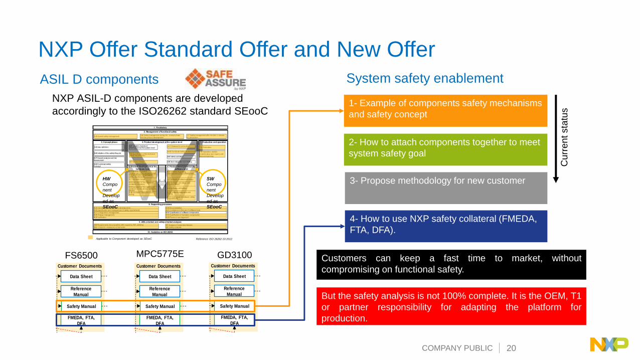
NXP Offer Standard Offer and New Offer
ASIL D components
NXP ASIL-D components are developed
accordingly to the ISO26262 standard SEooC
System safety enablement
Reference ISO 26262-10:2012Applicable to Component developed as SEooC
SW
Compo
nent
Develop
ed as
SEooC
HW
Compo
nent
Develop
ed as
SEooC
NPI LIFECYCLE
TO CES RQ ECQS
CONCEPT DEFINITION PLANNING EXECUTION CLOSURE
PROJECT LIFECYCLE
PDA PPA R PCPCAPI
(4-6/7) Safety
Concept RS & AS
(5-6) Requirements
Specifications (RS)
(5-7) Detailed Design
Specifications (DDTS)
(5-8,9) Initial Safety
Analysis
(5-10) Validation
Testing
(5-7) Block Level
Verification Testing
(8-13) Qualification
Testing
(5-7) Chip Level
Verification Testing
Implement
Safety Documentation Silicon TestingSimulation TestingFunctional Documentation
Diagram Color Schema Development Flow Requirement Traceability
Fault Injection Testing
Fault Injection Testing
Fault Injection Testing
Input Requirements
Standard
Customer
Marketing (MRD)
Internal
Product
Requirements (PRD)
Architectural
Specification (AS)
Data Sheet
Reference
Manual
Safety Manual
FMEDA, FTA,
DFA
(7-5) Production
Testing
Customer Documents
Input Document
PI Gate
Define product type
QM or ISO 26262
R Gate
Product Functional Safety
Assessment Report &
Safety Case
Common to HW and SW
development Model
MPC5775E GD3100FS6500
NPI LIFECYCLE
TO CES RQ ECQS
CONCEPT DEFINITION PLANNING EXECUTION CLOSURE
PROJECT LIFECYCLE
PDA PPA R PCPCAPI
(4-6/7) Safety
Concept RS & AS
(5-6) Requirements
Specifications (RS)
(5-7) Detailed Design
Specifications (DDTS)
(5-8,9) Initial Safety
Analysis
(5-10) Validation
Testing
(5-7) Block Level
Verification Testing
(8-13) Qualification
Testing
(5-7) Chip Level
Verification Testing
Implement
Safety Documentation Silicon TestingSimulation TestingFunctional Documentation
Diagram Color Schema Development Flow Requirement Traceability
Fault Injection Testing
Fault Injection Testing
Fault Injection Testing
Input Requirements
Standard
Customer
Marketing (MRD)
Internal
Product
Requirements (PRD)
Architectural
Specification (AS)
Data Sheet
Reference
Manual
Safety Manual
FMEDA, FTA,
DFA
(7-5) Production
Testing
Customer Documents
Input Document
PI Gate
Define product type
QM or ISO 26262
R Gate
Product Functional Safety
Assessment Report &
Safety Case
Common to HW and SW
development Model
1- Example of components safety mechanisms
and safety concept
2- How to attach components together to meet
system safety goal
3- Propose methodology for new customer
4- How to use NXP safety collateral (FMEDA,
FTA, DFA).
Customers can keep a fast time to market, without
compromising on functional safety.
But the safety analysis is not 100% complete. It is the OEM, T1
or partner responsibility for adapting the platform for
production.
Cu
rre
ntsta
tus

COMPANY PUBLIC 21
NXP Offer Standard Offer and New Offer
ASIL D components
NXP ASIL-D components are developed accordingly
to the ISO 26262 standard SEooC
Reference ISO 26262-10:2012Applicable to Component developed as SEooC
SW
Component
Developed
as SEooC
HW
Component
Developed
as SEooC
Safety enablement kit
NPI LIFECYCLE
TO CES RQ ECQS
CONCEPT DEFINITION PLANNING EXECUTION CLOSURE
PROJECT LIFECYCLE
PDA PPA R PCPCAPI
(4-6/7) Safety
Concept RS & AS
(5-6) Requirements
Specifications (RS)
(5-7) Detailed Design
Specifications (DDTS)
(5-8,9) Initial Safety
Analysis
(5-10) Validation
Testing
(5-7) Block Level
Verification Testing
(8-13) Qualification
Testing
(5-7) Chip Level
Verification Testing
Implement
Safety Documentation Silicon TestingSimulation TestingFunctional Documentation
Diagram Color Schema Development Flow Requirement Traceability
Fault Injection Testing
Fault Injection Testing
Fault Injection Testing
Input Requirements
Standard
Customer
Marketing (MRD)
Internal
Product
Requirements (PRD)
Architectural
Specification (AS)
Data Sheet
Reference
Manual
Safety Manual
FMEDA, FTA,
DFA
(7-5) Production
Testing
Customer Documents
Input Document
PI Gate
Define product type
QM or ISO 26262
R Gate
Product Functional Safety
Assessment Report &
Safety Case
Common to HW and SW
development Model
MPC5775E GD3100FS6500
NPI LIFECYCLE
TO CES RQ ECQS
CONCEPT DEFINITION PLANNING EXECUTION CLOSURE
PROJECT LIFECYCLE
PDA PPA R PCPCAPI
(4-6/7) Safety
Concept RS & AS
(5-6) Requirements
Specifications (RS)
(5-7) Detailed Design
Specifications (DDTS)
(5-8,9) Initial Safety
Analysis
(5-10) Validation
Testing
(5-7) Block Level
Verification Testing
(8-13) Qualification
Testing
(5-7) Chip Level
Verification Testing
Implement
Safety Documentation Silicon TestingSimulation TestingFunctional Documentation
Diagram Color Schema Development Flow Requirement Traceability
Fault Injection Testing
Fault Injection Testing
Fault Injection Testing
Input Requirements
Standard
Customer
Marketing (MRD)
Internal
Product
Requirements (PRD)
Architectural
Specification (AS)
Data Sheet
Reference
Manual
Safety Manual
FMEDA, FTA,
DFA
(7-5) Production
Testing
Customer Documents
Input Document
PI Gate
Define product type
QM or ISO 26262
R Gate
Product Functional Safety
Assessment Report &
Safety Case
Common to HW and SW
development Model
NPI LIFECYCLE
TO CES RQ ECQS
CONCEPT DEFINITION PLANNING EXECUTION CLOSURE
PROJECT LIFECYCLE
PDA PPA R PCPCAPI
(4-6/7) Safety
Concept RS & AS
(5-6) Requirements
Specifications (RS)
(5-7) Detailed Design
Specifications (DDTS)
(5-8,9) Initial Safety
Analysis
(5-10) Validation
Testing
(5-7) Block Level
Verification Testing
(8-13) Qualification
Testing
(5-7) Chip Level
Verification Testing
Implement
Safety Documentation Silicon TestingSimulation TestingFunctional Documentation
Diagram Color Schema Development Flow Requirement Traceability
Fault Injection Testing
Fault Injection Testing
Fault Injection Testing
Input Requirements
Standard
Customer
Marketing (MRD)
Internal
Product
Requirements (PRD)
Architectural
Specification (AS)
Data Sheet
Reference
Manual
Safety Manual
FMEDA, FTA,
DFA
(7-5) Production
Testing
Customer Documents
Input Document
PI Gate
Define product type
QM or ISO 26262
R Gate
Product Functional Safety
Assessment Report &
Safety Case
Common to HW and SW
development Model
How to attach our components and
follow a methodology to certify the
safety goal of the system?

COMPANY PUBLIC 22
Step 1: System Description
System description:
The power inverter control energy conversion
between an electric source (e.g. battery) and the
mechanical shaft of the motor based on torque
requested from Vehicle Control Unit (VCU).
MotorPhases Current
Motor Position and temperature
DC_bus voltage
Vehicle Control Unit Torque
Phases current
Power Inverter Module
Hazard analysis and risk assessment:
HAZ_01: Generate a torque without receivingrequest from VCU.
HAZ_02: Generate higher torque values asrequest from VCU.
HAZ_03: …
Safety Goal:
SG_01: Avoid generating torque that exceeds
the commanded value from VCU (ASIL D) .
SG_02:..

COMPANY PUBLIC 23
Step 2: Assumption and Functional Requirement
Functional requirement: (What is the main function of our system?)
Power Inverter Module
FR1: Receive and Interpret the command
FR2: Measure the state of the System (Phase current, Motor Position,
Battery voltage and Temperature)
FR4: Report Status to VCU
Motor
Vehicle Control Unit
FR3: Control the Phase current based on the torque command

COMPANY PUBLIC 24
Step 3: Functional Requirement to Functional Safety
Requirement
Power Inverter Module
FR1: Receive and Interpret the command
FR2: Measure the state of the System (Phase current, Motor Position,
Battery voltage and Temperature)
FR4: Report Status to VCU
Motor
Vehicle Control Unit
FR3: Control the Phase current based on the torque command
FR1: (Command) The Inverter shall receive and interpret the command from VCU.System Safe
StateFTTI ASIL
FSR1.1 The Inverter shall not apply torque if no command have been received D
FSR1.2 The Inverter shall not apply torque if the received command is incorrect D
FSR1.3 The inverter shall deactivate torque based on a request from VCU D
FSR1.4The inverter shall limit the torque requested by VCU if the command is outside
of plausible range.D
FSR1.5The inverter shall deactivate torque if the communication with VCU is
interruptedD
Functional requirement: (What are the system functions to guarantee we do not violate
our Safety goals ?)

COMPANY PUBLIC 25
Step 4 Define System Safe StateTe=1.5(λm.iq+(Ld−Lq)id.iq),
Safe State description for SG_01:
In the abnormal safe state, the electric motor shall achieve 0 torque output.
Option 1: The MCU can control Id and Iq to achieve 0 Torque => Control Failsafe
Option 2: We can control the state of the IGBT to achieve 0 Torque => Logic Failsafe (with or without MCU)
M M
M M
HS short Iq=0 Te=0 LS short Iq=0 Te=0
Te=0 only if BEMF <DC bus Te=0 but needs action from VCU to open contactor
ID Description
SS1 Normal Operation
SS2 Logic Failsafe
SS3 Control Failsafe (0 Torque control)
SS4 Send warning to VCU
SS5 Follow Safety Request from VCU

COMPANY PUBLIC 26
Safety Architecture
Safe State solution
AND(CPLD)
GD
3100
_H
S_A
FSENB _HS_A
FSTATE_HS_A
PWM_HS_A
PWM_ALT_HS_A
IGBT_state
INTB_HS_A
GD
3100
_H
S_A
FSENB _LS_A
FSTATE_LS_A
PWM_LS_A
PWM_ALT_LS_A
IGBT_state
INTB_LS_A
GD
3100
_H
S_A
FSENB _HS_B
FSTATE_HS_B
PWM_HS_B
PWM_ALT_HS_B
IGBT_state
INTB_HS_A
GD
3100
_H
S_A
FSENB _LS_B
FSTATE_LS_B
PWM_LS_B
PWM_ALT_LS_B
IGBT_state
INTB_LS_B
GD
3100
_H
S_A
FSENB _HS_C
FSENB_HS_C
PWM_HS_C
PWM_ALT_HS_C
IGBT_state
INTB_HS_A
GD
3100
_H
S_A
FSENB _LS_C
FSTATE_LS_C
PWM_LS_C
PWM_ALT_LS_C
IGBT_state
INTB_LS_C
AND(CPLD)
MC
U
INTB_HS
INTB_LS
INTB_HS_A
INTB_LS_A
INTB_HS_B
INTB_LS_B
INTB_HS_C
INTB_LS_C
ACK_FS65
FSEN_MCU_B
FSSTATE_HS_MCU
FSSTATE_LS_MCU
AND(CPLD)
FS65
IO5
IO4
FS0_B
IO3
IO2
INT
FCCU0
FCCU1
SPIx4
RST
INT
SPIx4
RST
AND
FSEN_ACK
CPLDFSLOGIC
FS65_FSb0
MCU_FSen
INT_LS
INT_HS
FSSTATE_HS_MCU
FSSTATE_LS_MCU
FSSTATE_HS_MCU
FSSTATE_LS_MCU
Safe state IO:
The GD3100 can report
error on INT pins
The IO4/IO5 of FS65
can manage GD error
with acknowledgement
of MCU
The FS65 can generate
safe state output with
FS0b
The IGBT state can be
controlled with FSENB
and FSSTATE pins of
GD3100

COMPANY PUBLIC 27
Failure in MCU and HS fault (SS= HS_Short)
AND(CPLD)
GD
31
00
_H
S_A
FSENB _HS_A
FSTATE_HS_A
PWM_HS_A
PWM_ALT_HS_A
IGBT_state
INTB_HS_A
GD
31
00
_H
S_A
FSENB _LS_A
FSTATE_LS_A
PWM_LS_A
PWM_ALT_LS_A
IGBT_state
INTB_LS_A
GD
31
00
_H
S_A
FSENB _HS_B
FSTATE_HS_B
PWM_HS_B
PWM_ALT_HS_B
IGBT_state
INTB_HS_A
GD
31
00
_H
S_A
FSENB _LS_B
FSTATE_LS_B
PWM_LS_B
PWM_ALT_LS_B
IGBT_state
INTB_LS_B
GD
31
00
_H
S_A
FSENB _HS_C
FSENB_HS_C
PWM_HS_C
PWM_ALT_HS_C
IGBT_state
INTB_HS_A
GD
31
00
_H
S_A
FSENB _LS_C
FSTATE_LS_C
PWM_LS_C
PWM_ALT_LS_C
IGBT_state
INTB_LS_C
AND(CPLD)
MC
U
INTB_HS
INTB_LS
INTB_HS_A
INTB_LS_A
INTB_HS_B
INTB_LS_B
INTB_HS_C
INTB_LS_C
ACK_FS65
FSEN_MCU_B
FSSTATE_HS_MCU
FSSTATE_LS_MCU
AND(CPLD)
FS6
5
IO5
IO4
FS0_B
IO3
IO2
INT
FCCU0
FCCU1
SPIx4
RST
INT
SPIx4
RST
AND
FSEN_ACK
CPLDFSLOGIC
FS65_FSb0
MCU_FSen
INT_LS
INT_HS
FSSTATE_HS_MCU
FSSTATE_LS_MCU
FSSTATE_HS_MCU
FSSTATE_LS_MCU

COMPANY PUBLIC 28
Failure in MCU only (SS= HS_Short)
AND(CPLD)
GD
31
00
_H
S_A
FSENB _HS_A
FSTATE_HS_A
PWM_HS_A
PWM_ALT_HS_A
IGBT_state
INTB_HS_A
GD
31
00
_H
S_A
FSENB _LS_A
FSTATE_LS_A
PWM_LS_A
PWM_ALT_LS_A
IGBT_state
INTB_LS_A
GD
31
00
_H
S_A
FSENB _HS_B
FSTATE_HS_B
PWM_HS_B
PWM_ALT_HS_B
IGBT_state
INTB_HS_A
GD
31
00
_H
S_A
FSENB _LS_B
FSTATE_LS_B
PWM_LS_B
PWM_ALT_LS_B
IGBT_state
INTB_LS_B
GD
31
00
_H
S_A
FSENB _HS_C
FSENB_HS_C
PWM_HS_C
PWM_ALT_HS_C
IGBT_state
INTB_HS_A
GD
31
00
_H
S_A
FSENB _LS_C
FSTATE_LS_C
PWM_LS_C
PWM_ALT_LS_C
IGBT_state
INTB_LS_C
AND(CPLD)
MC
U
INTB_HS
INTB_LS
INTB_HS_A
INTB_LS_A
INTB_HS_B
INTB_LS_B
INTB_HS_C
INTB_LS_C
ACK_FS65
FSEN_MCU_B
FSSTATE_HS_MCU
FSSTATE_LS_MCU
AND(CPLD)
FS6
5
IO5
IO4
FS0_B
IO3
IO2
INT
FCCU0
FCCU1
SPIx4
RST
INT
SPIx4
RST
AND
FSEN_ACK
CPLDFSLOGIC
FS65_FSb0
MCU_FSen
INT_LS
INT_HS
FSSTATE_HS_MCU
FSSTATE_LS_MCU
FSSTATE_HS_MCU
FSSTATE_LS_MCU

COMPANY PUBLIC 29
Failure in MCU and HS fault (SS= LS_Short)
AND(CPLD)
GD
31
00
_H
S_A
FSENB _HS_A
FSTATE_HS_A
PWM_HS_A
PWM_ALT_HS_A
IGBT_state
INTB_HS_A
GD
31
00
_H
S_A
FSENB _LS_A
FSTATE_LS_A
PWM_LS_A
PWM_ALT_LS_A
IGBT_state
INTB_LS_A
GD
31
00
_H
S_A
FSENB _HS_B
FSTATE_HS_B
PWM_HS_B
PWM_ALT_HS_B
IGBT_state
INTB_HS_A
GD
31
00
_H
S_A
FSENB _LS_B
FSTATE_LS_B
PWM_LS_B
PWM_ALT_LS_B
IGBT_state
INTB_LS_B
GD
31
00
_H
S_A
FSENB _HS_C
FSENB_HS_C
PWM_HS_C
PWM_ALT_HS_C
IGBT_state
INTB_HS_A
GD
31
00
_H
S_A
FSENB _LS_C
FSTATE_LS_C
PWM_LS_C
PWM_ALT_LS_C
IGBT_state
INTB_LS_C
AND(CPLD)
MC
U
INTB_HS
INTB_LS
INTB_HS_A
INTB_LS_A
INTB_HS_B
INTB_LS_B
INTB_HS_C
INTB_LS_C
ACK_FS65
FSEN_MCU_B
FSSTATE_HS_MCU
FSSTATE_LS_MCU
AND(CPLD)
FS6
5
IO5
IO4
FS0_B
IO3
IO2
INT
FCCU0
FCCU1
SPIx4
RST
INT
SPIx4
RST
AND
FSEN_ACK
CPLDFSLOGIC
FS65_FSb0
MCU_FSen
INT_LS
INT_HS
FSSTATE_HS_MCU
FSSTATE_LS_MCU
FSSTATE_HS_MCU
FSSTATE_LS_MCU

COMPANY PUBLIC 30
Safety Function Architecture
PIM
MCU Domain
Command
Sensing domain
Torque execution
Safe state control
High voltage switching domain
Safe state logic control
Power Domain
Communication domain
Resolver Domain
Analog Domain
Torque control
Monitoring
Power monitor
MCU Monitoring
Local Fast IGBT protection
HV IGBT switch
MCU Monitoring
Command integrity check
Sensor chain monitoring
Resolver Domain
Resolver Monitor
Analog Sensing
Report
Motor
Functional execution
Monitoring
Safe state control
Power
Execution
Monitoring
Safe state
ASIL-B
ASIL-D
QM
Power

COMPANY PUBLIC 31
Key Safety Concepts
Safety concept
ASIL D gate driver to guarantee fast protection of IGBT
Safe state logical connection of FSBC, MCU and GD3100 safety IO to guarantee
correct safe state
MCU monitoring by FSBC to detect HW and SW fault
ASIL D position sensing with independent eTPU resolver and eTPU diagnostic
software
ASIL D phase current with 3 current senses
Software ASIL D decomposition to reduce software complexity (execution and
monitoring)
VCU command monitoring to guarantee integrity of communication

COMPANY PUBLIC 32
Inverter System Safety Package
External third
party certification
Includes other partner stack
Customized Safety
analysis with Customer
Add-On software library(link to safety concept)
Delivered upon request
for customer under NDA
Existing safety collateral Certified NXP Components
ASIL D Certification documentation
Certified Autosar MCAL
Safety
Concept
Safety
Application
Recipe
Example
FTA,
FMEA,
FMEDA
Partial
Test
Plan
Safety SDK
Safety MC Service
Safety MC
Application
Complete FTA, FMEA,
FMEDA, Test plan
Additional third party
software
Certification

COMPANY PUBLIC 33
Key Power Inverter Platform
Components

COMPANY PUBLIC 34
GD3100 IGBT GDIC With Integrated HV Isolation
Differentiation:• Fast short circuit protection via direct feedback through i-sense IGBTs
• High speed over current protection with soft shutdown
• SPI interface for ASIL C/D monitoring/reporting and programmability
• Integrated temperature sense soft shutdown for system protection
• Integrated galvanic signal isolation
• Compact 10 x 18 mm SOIC package for reduced PCB area
Applications:• HEV Motor Inverters
• HV UPS Inverters
• Alternate Energy Inverters
32-Pin
SOIC-WB
PART # PKG SAMPLES RELEASE
MC33HB3100EK SOICWB32 NOW (P2.2) 4Q’18
Logic Block 1
SCLK
CSB
MOSI
MISO
SPI
PWM
FSSTATE
INTB
Config, DT Control,Cross Conduction,Flt Management,
Safing
VSUP
TSENSEA
AMC
GH
VEE
(2 pins)
DESAT
GND1
(2 pins)
GND2
(2 pins)RX TX
INT
DATA_IN
DATA_OUT
PWMALT SerialComm
GL
RX TX
Logic Block 2
CLAMP
ISENSE
TEMP IGBT
AMUXIN
TX RX
NC13
PWM
TX RX
TEMP IC
AOUTDuty Cycle Encoder
VCC
VREF
(5 V, 1 %,
20 mA)GND2
VCCREG
AMUX & 10-bit ADC
VCC
SerialComm
Fault Management,
Conf. Registers,
fault registers,Gate control
logic,ASIL test control
FSENB
VDD
Gate Drive
Control
Active Vce Clamp, Desat
Charge and Discharge
Control
Active Miller Clamp
IGBT Current Sense
Safing Logic
Deadtime Control
IGBT Temp Sense
Power
Management 1VCCLV,
Bandgap,
References,
Oscillators
UV/OVLO, etc.
Power
Management 2VCCHV,
Bandgap,
References,
Oscillators
UV/OVLO, etc.
NC2
FSISO
INTB/VGEMON
Advanced gate driver for high voltage power IGBTs with integrated high voltage isolator and
new current sense features to minimize short circuit stress & reduce IGBT die size

COMPANY PUBLIC 35
MPC5775E MCU for Power Inverter Control
Cores • Two independent z7 dual issue 264 MHz cores
Including VLE, SPE1.1, FPU , MMU
16 kB i-cache & 16 kB data-cache w/ coherency
• Single z7 264 MHz lockstep core
• Integrated security w/ PASS, TDM (Tamper Detection), & CSE2 (Crypto)
Memory• 4.25 MB Flash RWW w/ ECC (including 4 x 64 kB EEPROM)
• 512 kB SRAM w/ ECC (up to 48 KB standby)
• 45 kB eTPU RAM , 32 kB data cache (w/ line locking)
I/O & System• Up to 70 ch eQADC from 4 converters w/12-bit resolution
On-chip temperature sensor and VGA (x1,x2,x4)
12 x Decimation Filters w/ hardware knock integrators
• Timers – up to 128 channels (96 ch eTPU2+ and 32 ch eMIOS)
• 2 x 64ch eDMA support (128ch total)
• 6 x CAN ports (4 x FlexCAN + 2 x MCAN) and Ethernet
• DSPI – 5 channels (2 supporting µSec ch.)
• eSCI – 6 channels (2 supporting uSec ch.)
• Reaction module w/ 8 channels for current control
• Up to 12ch SENT
• 1 x CRC unit – w/ 3 independent channels,
• 4 x protected port outputs, MPU and MMU
• FMPLL + PLL
• Safety Monitors – e2eECC, CLK, Voltage, Fault Collection
COMPUTATIONAL SHELL
4.25MB Flash(4x64kB EEPROM)
512k SRAM(48k Standby)
SRAM
Control
CACHE16k D-Cache
16k I-Cache
VLE
FPU
MPU
Cross Bar Switch with ECC
STM
INTC
SWT
DEBUG
Flash Control
MMU
Bridge
B
Bridge
A
DTS
MMU
Nexus 3+
JTAG
PowerPC™
e200420
e200Z7 lock-step
STM
INTC
SWT
2 x eTPU2+
16ch eMIOS
FCCU
3 x eSCI
2 x DSPI
CMU
(I) Glitch Filter
1 x eQADC
PMU
2 x SIUx
1 x MCAN-FD
2 x FlexCAN
Confidential and
Proprietary
1 x
MC
AN
-FD
8ch R
eactio
n
FM
PLL +
PLL
CR
C (3
ch)
16 x
Sem
aphore
s
DT
S fo
r DA
Q
Safe
ty Module
DT
M (N
exus)
Tem
p S
ensor
1 x
eT
PU
2+
4 x
PIT
16 c
heM
IOS
1 x
eQ
AD
C
12 x
DE
CF
IL
3 x
DS
PI (M
SB
)
3 x
eS
CI
(MS
B)
PA
SS
/ TD
M
CS
E2
BA
M
2 x
Fle
xC
AN
64ch eDMASPE1.1
16k D-Cache
16k I-Cache
VLE
MMU
FPU
SPE1.1
e200Z7
(dual issue)e200Z7
(dual issue)
SRAM
Control
64ch eDMA
Ethernet
SECURITY
CSE2
SENT
Available in 416 MAPBGA package with -40 to 125C Ta operating range
FS651x
Attach

COMPANY PUBLIC 36
FS65 Safety SBC Safety Monitoring Capabilities
Independent Fail Safe State
Machine• Physical & electrical
independance to fit for ASILD
• Power management monitoring
unit (UV / OV)
• Analog & digital built in self test
to minimize latent faults
• Own reference & supply to
reduce common cause failure
Fail Safe Pin (FS0b) • Redundant system fail safe
enabler
• Second fail safe pin to assert
safety path with configurable
delay after failure
Advanced Watchdog• Challenger
• Replace external MCU
monitoring
MCU Monitoring • FCCU: fault collection control
unit
• Monitor dual-core lock step
modes mcus
RSTb – Fail Silent Mode• Configurable RSTb activation
giving more system availability
HW Redundancy• Vcore external monitoring
Safety SBC
FS65
Safety MCU

COMPANY PUBLIC 37
750 V/800 A 6-in-1 Power Inverter Module
Features:
• 750 V/800 A 6-in-1 3-phase power inverter module
• Reverse-conducting IGBT with integrated temperature sensor
• Integrated ‘i-Sense’ current sensor for fast over-current detection
• 162mm × 117mm × 24 mm compact direct-cooling water-jacket aluminum housing with new thin fin structure
• Flange structure at cooling water IN/OUT for 30% lower thermal resistance vs conventional fin type heat sink.
• 175℃ guaranteed operating temperature range
Application Example:
• 70~120 kW motor output power
− Fsw = 6 kHz
− Coolant temp = 65℃
− Coolant flow rate = 10L/min
− Vdc = 450 V
− Ipeak = 460 Arms @ 1s
− Icont = 430 Arms
Top view
Bottom view

COMPANY PUBLIC 38
Summary

COMPANY PUBLIC 39
Summary
• NXP offers a portfolio of products that enables customers to create a HV traction inverter solution which meets ASIL-C/ASIL-D safety goals
• NXP is enhancing this solution by developing a enablement platform system solution (inverter + motor) which incorporates the building blocks for system-level functional safety as well highly functional motor control application software
• Customers can use all or parts of this enablement platform “as is” to kick-start their traction motor system development , or engage with NXP or our third-party (VEPCO) for customization or development of other capabilities
• NXP envisions extending this enablement platform to address the requirements of other electrification systems applications, such as HV DC/DC converters, On-Board Chargers, and Vehicle or Power Control Units.
COMPANY PUBLIC 40
Safety Deliverables

COMPANY PUBLIC 41
Safety Manual
Current Status on Safety
Complete and
needs to be
reviewed
HARA
Safety GoalSystem
description
and
Assumption
Functional Safety
requirement
Technical Safety
requirement
MCU/SW
Safe state Definition
Technical Safety
requirement HV
GD
Technical Safety
requirement
FSBC and
FSLogic
Technical Safety
requirement
Sensing
Safety
Mechanism
MCU/SW
Safety
Mechanism HV
GD
Safety
Mechanism FSBC
and FSLogic
Safety
Mechanism
Sensing
Functional Safety
concept
Partially complete
Review in one week

COMPANY PUBLIC 42
Partner Deliverables
• Signal chain components and support
• System enablement driver software
• Basic safety case and software
• SW development SDK
• Level 1 platform technical support
• IGBT power module
Platform system engineering & development
Prototype HW & SW development
Level 2 platform technical support
Contract system engineering services
HV Power Inverter Enablement Platform
Enclosure
Control Board
Inverter Board
Module
cooling
Bus
bar
12V
CAN
400V
BATT
3 Phase
Motor
Curr
sense
Link
cap
Software
Platform Electronics

COMPANY PUBLIC 43
Mastering xEV Power for Efficient Energy Management
MC
U
SB
C
CO
MM
Drive
r
AF
E
MP
C5
77
5B
FS
65
TJ
A1
04
x
eS
wit
ch
BC
C77x
MP
C5
77
5E
FS
65
TJ
A1
04
x
GD
31
00
So
ftw
are
res
olv
er
S3
2K
x
FS
45
UJ
A1
16
x
TJ
A1
4x
x
S3
2K
+
FS
26
TJ
A1
04
x
S3
2K
+
FS
26
TJ
A1
04
x
Motor control,
inverter, HCU
DC/DC voltage
domain converter
On-board charger
AC/DC converter
Battery
management
system
48V eMachine
(BSG, ISG, HVAC)Fo
cu
s A
pp
lica
tio
ns
Optimized power system control
with NXP ePowerMaster portfolio

NXP, the NXP logo, and NXP secure connections for a smarter world are trademarks of NXP B.V. All other product or service names are the property of their respective owners. © 2018 NXP B.V.
www.nxp.com