highlights from dipac 2009 - cernaccelconf.web.cern.ch/accelconf/biw2010/talks/thimnb01_talk.pdf ·...
TRANSCRIPT
Volker Schlott BIW 2010, Santa Fe, May 2nd - 6th 2010
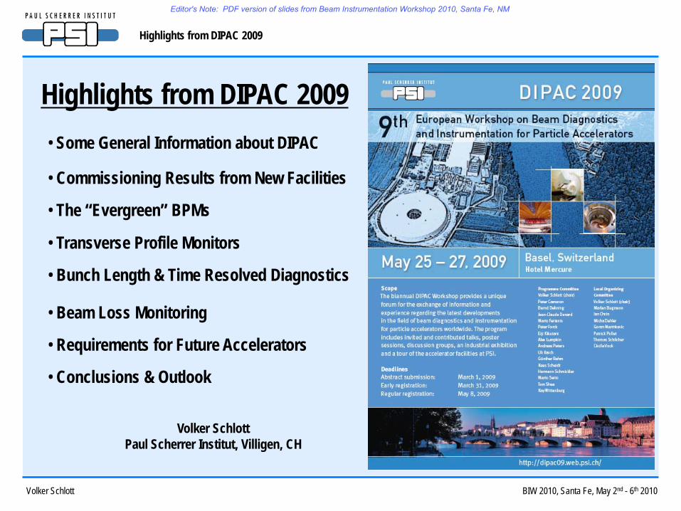
Highlights from DIPAC 2009
Highlights from DIPAC 2009• Some General Information about DIPAC
• Commissioning Results from New Facilities
• The “Evergreen” BPMs
• Transverse Profile Monitors
• Bunch Length & Time Resolved Diagnostics
• Beam Loss Monitoring
• Requirements for Future Accelerators
• Conclusions & Outlook
Volker SchlottPaul Scherrer Institut, Villigen, CH
Editor's Note: PDF version of slides from Beam Instrumentation Workshop 2010, Santa Fe, NM

Volker Schlott BIW 2010, Santa Fe, May 2nd - 6th 2010
Highlights from DIPAC 2009
1997 INFN-Frascati, Italy 129 11 12 50 4Year Location Participants Inv. Talks Contrib. Talks Posters Discussions
1999 Daresbury Lab., UK 103 8 12 31 42001 ESRF, France 150 12 11 42 62003 GSI, Germany 131 10 11 56 32005 CERN, Switzerland 148 12 8 92 62007 ELETTRA, Italy 189 10 10 117 4
2009 PSI, Switzerland 206 10 14 118 -
DIPAC 2009: 206 Participants from 18 Countries World-Wide- 153 colleagues from 12 European countries - 2 colleagues from (South) Africa- 19 colleagues from the US - 19 sponsors and industrial exhibitors- 13 colleagues from Asia and Australia
DIPAC Participants & Scientific Programs (1997 – 2009)
Growing interest in Diagnostics might be caused by…:- tremendous performance and reliability of existing diagnostics, FBs and instrumentation- more complex diagnostics & instrumentation for new and advanced accelerator facilities- new areas of instrumentation like e.g.: lasers, synchronization, micro-positioning, X-rays etc…
Editor's Note: PDF version of slides from Beam Instrumentation Workshop 2010, Santa Fe, NM
Volker Schlott BIW 2010, Santa Fe, May 2nd - 6th 2010
Highlights from DIPAC 2009
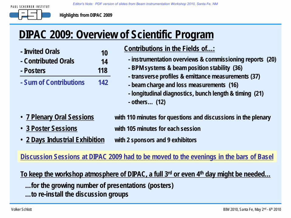
- Invited Orals- Contributed Orals- Posters- Sum of Contributions
• 7 Plenary Oral Sessions with 110 minutes for questions and discussions in the plenary• 3 Poster Sessions with 105 minutes for each session• 2 Days Industrial Exhibition with 2 sponsors and 9 exhibitors
Discussion Sessions at DIPAC 2009 had to be moved to the evenings in the bars of Basel
- instrumentation overviews & commissioning reports (20)- BPM systems & beam position stability (36)- transverse profiles & emittance measurements (37)- beam charge and loss measurements (16)- longitudinal diagnostics, bunch length & timing (21)- others… (12)
DIPAC 2009: Overview of Scientific ProgramContributions in the Fields of…:10
14118142
To keep the workshop atmosphere of DIPAC, a full 3rd or even 4th day might be needed……for the growing number of presentations (posters)…to re-install the discussion groups
Editor's Note: PDF version of slides from Beam Instrumentation Workshop 2010, Santa Fe, NM
Volker Schlott BIW 2010, Santa Fe, May 2nd - 6th 2010
Highlights from DIPAC 2009
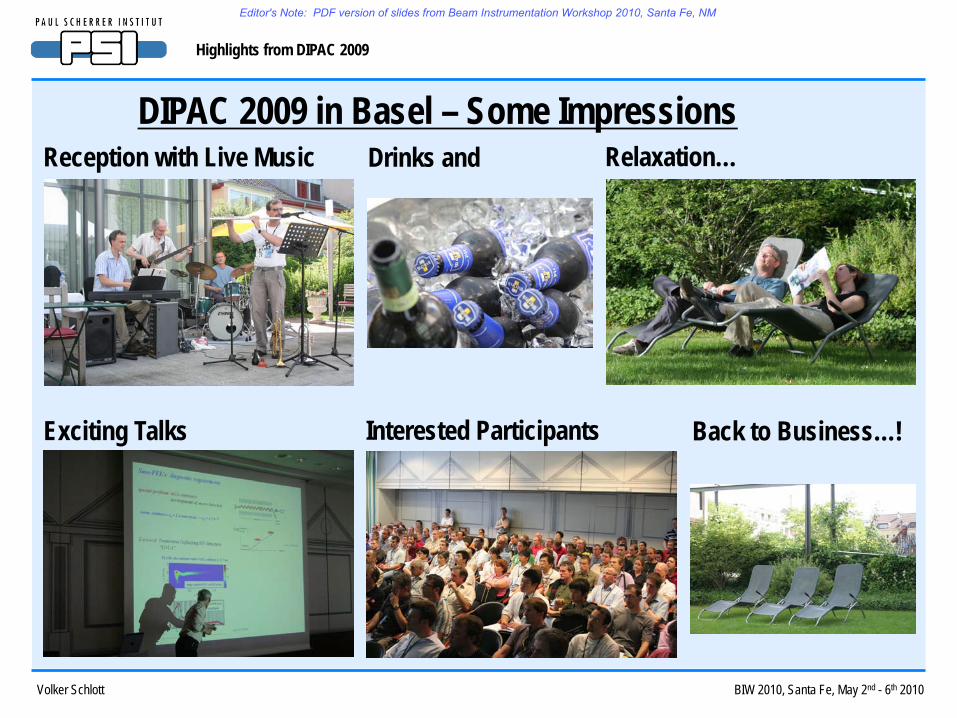
DIPAC 2009 in Basel – Some ImpressionsReception with Live Music Drinks and Relaxation…
Exciting Talks Back to Business…!Interested Participants
Editor's Note: PDF version of slides from Beam Instrumentation Workshop 2010, Santa Fe, NM

Volker Schlott BIW 2010, Santa Fe, May 2nd - 6th 2010
Highlights from DIPAC 2009
DIPAC 2009 in Basel – Some More ImpressionsPoster Sessions Industrial ExhibitionPlenary Discussions
Conference Dinner at Schloss Bottmingen PSI Visit
Editor's Note: PDF version of slides from Beam Instrumentation Workshop 2010, Santa Fe, NM

Volker Schlott BIW 2010, Santa Fe, May 2nd - 6th 2010
Highlights from DIPAC 2009
Performance and First Experiences with the LHC Beam Diagnosticscourtesy of Rhodri Jones / MOOA02
- 37 BTV Systems with 100% availability !!!- 1 mm thick alumina (scintillator) screens- 12 ∝m thick Tantalum foil OTR screens- all BTV stations equipped with both screens- alumina sensitivity: < 109 protons (first injections)- OTR sensitivity: ~ 2.109 protons (pilot bunch)- multiple OTR screens in beam (transfer lines)- multi-turn observations with OTR screens
Beam Profile Measurements (LHC TV System)1st LHC beam & turns
- 1054 BPMs with 99% availability !!!- beam threading around LHC ring- check of polarity errors - measure phase advances- threshold: ≥ 1.5.109 protons (pilot bunch)- short term resolution & stability: ≤ 10 ∝m (rms)- but: temp. drifts of electronics ~ 50 ∝m/°C
Beam Position Monitors
Editor's Note: PDF version of slides from Beam Instrumentation Workshop 2010, Santa Fe, NM

Volker Schlott BIW 2010, Santa Fe, May 2nd - 6th 2010
Highlights from DIPAC 2009
Performance and First Experiences with the LHC Beam Diagnosticscourtesy of Rhodri Jones / MOOA02
- > 4000 BLMs installed at likely loss locations- 50 cm long N2 filled (1.5 l) ionisation chambers- 10 cm long secondary emission monitors- designed for signal speed (85 ∝s) & reliability- dynamic range: > 109
- noise level: ~ 1% of pilot bunch→ quenchless injection @ 5.1011 protons
Beam Loss Monitors
- 2 BCMs installed to measure circulating beam- 4 ranges are provided simultaneously to cover
entire dynamic range from 2.109 to 5.1014 protons- sensitivity: ~ 7.108 (1.3 ∝A)- offset: ~ 2.5.109 (4.5 ∝A) still to be corrected
Beam Charge Monitors
green: BLM signals integrated over 5 s red: threshold settings
First circulating beam in ring 2 seen by BCTDC A (12/9/2008)
Conclusion: good start for all instrumentation systemsthanks to years of planning, testing & HW commissioning and good collaborations with other groups
Editor's Note: PDF version of slides from Beam Instrumentation Workshop 2010, Santa Fe, NM

Volker Schlott BIW 2010, Santa Fe, May 2nd - 6th 2010
Highlights from DIPAC 2009
Diagnostics for SPring8 / XFEL – Experience with SCSS Test Facilitycourtesy of Hirokazu Maesaka / MOOA03
- 56 cavity BPMs operating at 4760 MHz- compact TM110 & TM010 cavity design- electronics: IQ demodulation
Cavity Beam Position MonitorsSPring8 Cavity BPM
- YAG:Ce for low energy beam (< 100 MeV)- OTR: 0.1 mm thick SS foil
surface roughness tens of nm, flatness 3 ∝m- customized lens system
variable magnification (x1 and x4)
Beam Profile Monitors Variable Magnification Imaging System
Imaging System Design by Ray Tracing
OTR Image (250 MeV beam)
YAG:Ce Image (same beam)
13.4 ∝m(std. dev.)
15.8 ∝m(std. dev.)
Position Resolution: 200 nm Arrival Time Resolution: 25 fs
- position resolution: ~ 200 nm (@ 0.3 nC)- arrival time resolution: ~ 25 fs
grid distortion pattern
- spatial resolution: 2.5 ∝m (HWHM)
Editor's Note: PDF version of slides from Beam Instrumentation Workshop 2010, Santa Fe, NM

Volker Schlott BIW 2010, Santa Fe, May 2nd - 6th 2010
Highlights from DIPAC 2009
Other Reports on Accelerator Facility & Diagnostics Commissioning
- 6 GeV storage ring with 2304 m circumference, 100 mA beam current & extremely low emittance 1 nm !- commercial LIBERA Brilliance BPM electronics- transverse multi-bunch feedback available from the beginning- X-ray beam line for emittance diagnostics: pinhole with 20 ∝m resolution,
31 compound refractive Be lenses with 2 ∝m resolution- Hamamatsu C5680 streak camera for bunch length measurements using visible SR
PETRA III Light Source @ DESY (by Klaus Balewski – MOOB02)
- lasing 1.5 Å with nominal „250 pC mode“ and short-pulse, low emittance „20 pC mode“- 12 GHz cavity BPMs with σx ~ 440 nm, ⌠y ~ 230 nm resolution (by SLAC & Argonne NL collaboration)
(more about SLAC BPMs later…)
LCLS Commissioning @ SLAC (by Steve Smith – TUOC03)
- 3.5 GeV storage ring with 432 m circumference, 200 - 300 mA beam current & 3.9 / 11.2 nm emittance- commercial LIBERA Brilliance BPM electronics- visible light diagnostics beam line with…: visible light interferometer (< 10 ∝m res.) & streak camera
SSRF Light Source @ Shanghai (by Yongbin Leng – MOOB03)
Editor's Note: PDF version of slides from Beam Instrumentation Workshop 2010, Santa Fe, NM
Volker Schlott BIW 2010, Santa Fe, May 2nd - 6th 2010
Highlights from DIPAC 2009
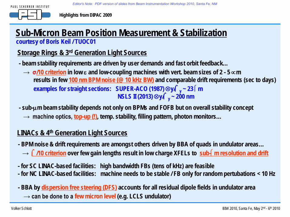
Sub-Micron Beam Position Measurement & Stabilizationcourtesy of Boris Keil / TUOC01
- beam stability requirements are driven by user demands and fast orbit feedback…→ σ/10 criterion in low ε and low-coupling machines with vert. beam sizes of 2 - 5 ∝m
results in few 100 nm BPM noise (@ 10 kHz BW) and comparable drift requirements (sec to days)examples for straight sections: SUPER-ACO (1987) ⊗y/⌠y ~ 23 m
NSLS II (2013) ⊗y/⌠y ~ 200 nm
Storage Rings & 3rd Generation Light Sources
- BPM noise & drift requirements are amongst others driven by BBA of quads in undulator areas…→ ⌠/10 criterion over few gain lengths result in low charge XFELs to sub-m resolution and drift
LINACs & 4th Generation Light Sources
- sub-µm beam stability depends not only on BPMs and FOFB but on overall stability concept→ machine optics, top-up (!), temp. stability, filling pattern, photon monitors…
- for SC LINAC-based facilities: high bandwidth FBs (tens of kHz) are feasible- for NC LINAC-based facilities: machine needs to be stable / FB only for random pertubations < 10 Hz
- BBA by dispersion free steering (DFS) accounts for all residual dipole fields in undulator area→ can be done to a few micron level (e.g. LCLS undulator)
Editor's Note: PDF version of slides from Beam Instrumentation Workshop 2010, Santa Fe, NM

Volker Schlott BIW 2010, Santa Fe, May 2nd - 6th 2010
Highlights from DIPAC 2009
BPM Pick-Up Types for Sub-Micron Beam Position Measurementscourtesy of Boris Keil / TUOC01 resonant stripline
„two-cavity“ BPMcourtesy of A Citterio (PSI)
courtesy of D. Lipka (DESY)
courtesy of L. Sørby (CERN)
current transformer BPM
Editor's Note: PDF version of slides from Beam Instrumentation Workshop 2010, Santa Fe, NM
Volker Schlott BIW 2010, Santa Fe, May 2nd - 6th 2010
Highlights from DIPAC 2009
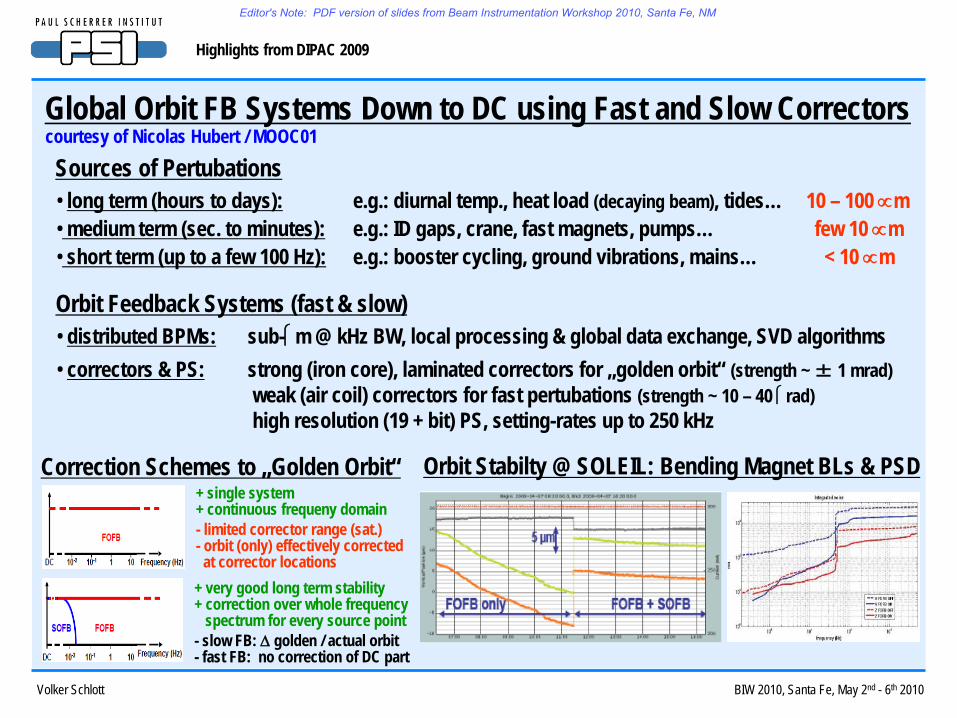
Global Orbit FB Systems Down to DC using Fast and Slow Correctors
• long term (hours to days): e.g.: diurnal temp., heat load (decaying beam), tides… 10 – 100 ∝m• medium term (sec. to minutes): e.g.: ID gaps, crane, fast magnets, pumps… few 10 ∝m• short term (up to a few 100 Hz): e.g.: booster cycling, ground vibrations, mains… < 10 ∝m
Sources of Pertubationscourtesy of Nicolas Hubert / MOOC01
• distributed BPMs: sub-m @ kHz BW, local processing & global data exchange, SVD algorithms• correctors & PS: strong (iron core), laminated correctors for „golden orbit“ (strength ~ ± 1 mrad)
weak (air coil) correctors for fast pertubations (strength ~ 10 – 40 rad)high resolution (19 + bit) PS, setting-rates up to 250 kHz
Orbit Feedback Systems (fast & slow)
Correction Schemes to „Golden Orbit“+ single system+ continuous frequeny domain- limited corrector range (sat.)- orbit (only) effectively corrected at corrector locations
+ very good long term stability+ correction over whole frequency
spectrum for every source point- slow FB: ∆ golden / actual orbit- fast FB: no correction of DC part
Orbit Stabilty @ SOLEIL: Bending Magnet BLs & PSD
Editor's Note: PDF version of slides from Beam Instrumentation Workshop 2010, Santa Fe, NM

Volker Schlott BIW 2010, Santa Fe, May 2nd - 6th 2010
Highlights from DIPAC 2009
Overview of FOFB Implementations in Storage Rings
Global Orbit FB Systems Down to DC using Fast and Slow Correctorscourtesy of Nicolas Hubert / MOOC01
Editor's Note: PDF version of slides from Beam Instrumentation Workshop 2010, Santa Fe, NM
Volker Schlott BIW 2010, Santa Fe, May 2nd - 6th 2010
Highlights from DIPAC 2009
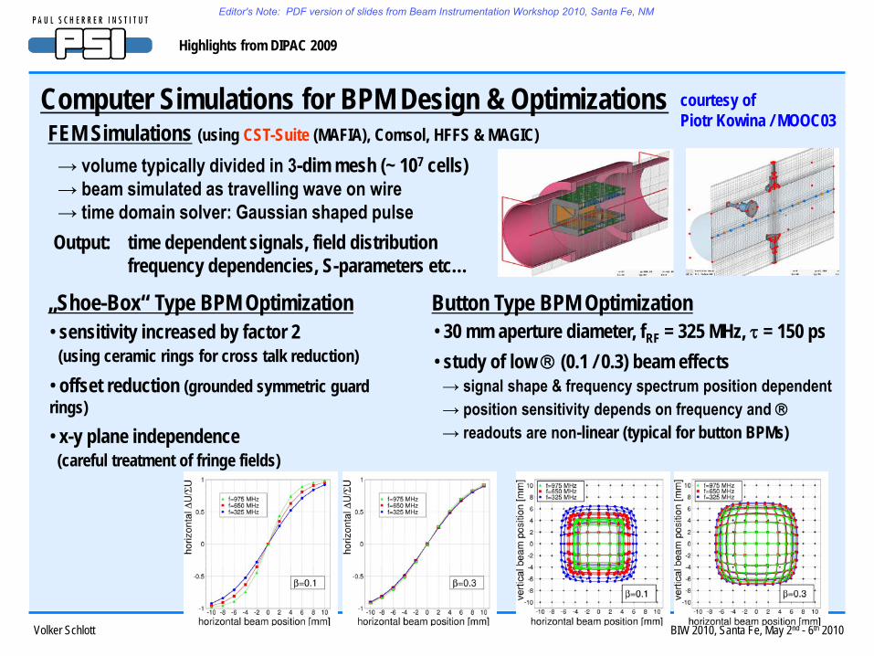
Computer Simulations for BPM Design & Optimizations courtesy of Piotr Kowina / MOOC03
→ volume typically divided in 3-dim mesh (~ 107 cells)→ beam simulated as travelling wave on wire→ time domain solver: Gaussian shaped pulse
Output: time dependent signals, field distributionfrequency dependencies, S-parameters etc…
FEM Simulations (using CST-Suite (MAFIA), Comsol, HFFS & MAGIC)
„Shoe-Box“ Type BPM Optimization• sensitivity increased by factor 2
(using ceramic rings for cross talk reduction)
• offset reduction (grounded symmetric guard rings)• x-y plane independence
(careful treatment of fringe fields)
Button Type BPM Optimization• 30 mm aperture diameter, fRF = 325 MHz, τ = 150 ps • study of low (0.1 / 0.3) beam effects
→ signal shape & frequency spectrum position dependent→ position sensitivity depends on frequency and → readouts are non-linear (typical for button BPMs)
Editor's Note: PDF version of slides from Beam Instrumentation Workshop 2010, Santa Fe, NM

Volker Schlott BIW 2010, Santa Fe, May 2nd - 6th 2010
Highlights from DIPAC 2009
Commissioning Results from LCLS Cavity BPMs courtesy of Steve Smith / TUOC03
• monopole & dipole cavity @ fRF = 11.384 GHz• cavities are 36 mm apart → 130 dB isolation• material copper, diameter 10 mm• 34 cavity BPMs along undulator, 2 in transport line
LCLS Cavity BPMs (collaboration between ANL & SLAC) x-porty-port monopol
mode
vertical dipolmode
• receiver: chassis underneath undulator stand3 channels (x,y,ref) – heterodyne receiverwaveguide in / coax outdown-conversion from X-band to 40 MHz
Calibration (movement: 5m steps) Resolution Histograms
σx ~ 440 nm
σy ~ 230 nm
z (m)
DFS Alignment ofLCLS Undulator(En: 4.3 – 13.64 GeV)
courtesy of H. Loos et al.4 / 3 / 2009
• digitizer: 4 channel VME ADC outside tunnel16 bit, up to 130 MS/sext. clock (119 MHz) sync. to LINAC RF
Editor's Note: PDF version of slides from Beam Instrumentation Workshop 2010, Santa Fe, NM
Volker Schlott BIW 2010, Santa Fe, May 2nd - 6th 2010
Highlights from DIPAC 2009
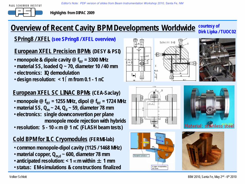
Overview of Recent Cavity BPM Developments Worldwide courtesy of Dirk Lipka / TUOC02
SPring8 / XFEL (see SPring8 / XFEL overview)
• monopole @ fRF = 1255 MHz, dipol @ fRF = 1724 MHz• material SS, Qm ~ 24, Qd ~ 59, diameter 78 mm• electronics: single downconvertion per plane
monopole mode rejection with hybrids• resolution: 5 - 10 ∝m @ 1 nC (FLASH beam tests)
European XFEL SC LINAC BPMs (CEA-Saclay)
• common monopole-dipol cavity (1125 / 1468 MHz)• material copper, Qm,d ~ 600, diameter 78 mm• anticipated resolution: < 1 ∝m within ± 1 mm• status: EM-simulations & constructions finalized
Cold BPM for ILC Cryomodules (FERMI-lab)
European XFEL Precision BPMs (DESY & PSI)• monopole & dipole cavity @ fRF = 3300 MHz• material SS, loaded Q ~ 70, diameter 10 / 40 mm• electronics: IQ demodulation• design resolution: < 1 m from 0.1 - 1 nC
Editor's Note: PDF version of slides from Beam Instrumentation Workshop 2010, Santa Fe, NM

Volker Schlott BIW 2010, Santa Fe, May 2nd - 6th 2010
Highlights from DIPAC 2009
Overview of Recent Cavity BPM Developments Worldwide courtesy of Dirk Lipka / TUOC02
• collaboration of UK & US institutes / universities• monopole & dipole cavity @ fRF = 2859 MHz• material copper, loaded Q ~ 600, diameter 36 mm• electronics: IQ demodulation• resolution: horiz. 0.53 m / vert. 0.46 m @ 2.6 nC
Cavity BPM for ILC Spectrometer
• collaboration of US & Japanese & European institutes• design: minimize X-Y contamination by rect. cavities
supress beam angle effect by thin cavity gap• X-port: fRF = 5707 MHz, QL ~ 2182• Y-port: fRF = 6421 MHz, QL ~ 1308• pipe shape: 6 and 12 mm apertures, material copper • electronics: down-conversion & IQ phase detection
Cavity BPM for ILC IP
• resolution: ~ 8.72 nm @ ~ 1.1 nC (2 nm desired)
Editor's Note: PDF version of slides from Beam Instrumentation Workshop 2010, Santa Fe, NM
Volker Schlott BIW 2010, Santa Fe, May 2nd - 6th 2010
Highlights from DIPAC 2009
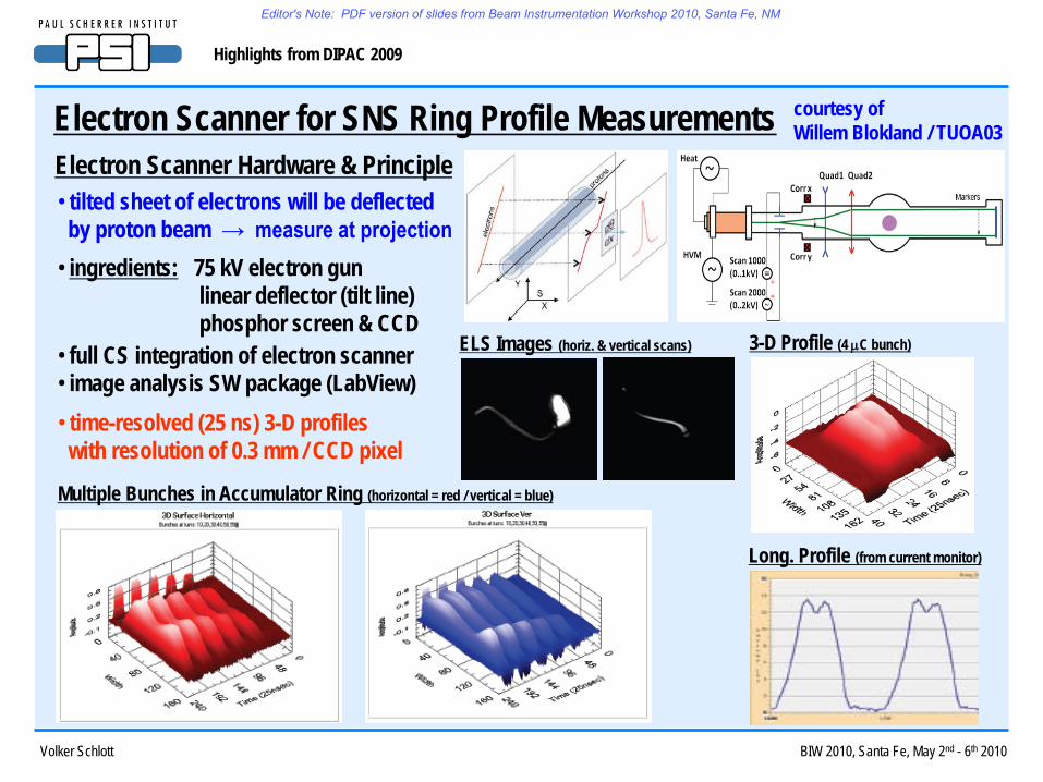
Electron Scanner for SNS Ring Profile Measurements courtesy of Willem Blokland / TUOA03
• tilted sheet of electrons will be deflectedby proton beam → measure at projection
Electron Scanner Hardware & Principle
• ingredients: 75 kV electron gunlinear deflector (tilt line)phosphor screen & CCD
• full CS integration of electron scanner• image analysis SW package (LabView)• time-resolved (25 ns) 3-D profileswith resolution of 0.3 mm / CCD pixel
ELS Images (horiz. & vertical scans) 3-D Profile (4 µC bunch)
Long. Profile (from current monitor)
Multiple Bunches in Accumulator Ring (horizontal = red / vertical = blue)
Editor's Note: PDF version of slides from Beam Instrumentation Workshop 2010, Santa Fe, NM
Volker Schlott BIW 2010, Santa Fe, May 2nd - 6th 2010
Highlights from DIPAC 2009
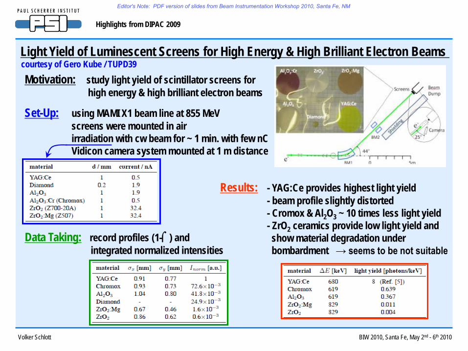
Light Yield of Luminescent Screens for High Energy & High Brilliant Electron Beams courtesy of Gero Kube / TUPD39
Data Taking: record profiles (1-⌠) and integrated normalized intensities
Results: - YAG:Ce provides highest light yield- beam profile slightly distorted- Cromox & Al2O3 ~ 10 times less light yield- ZrO2 ceramics provide low light yield andshow material degradation underbombardment → seems to be not suitable
Set-Up: using MAMI X1 beam line at 855 MeVscreens were mounted in airirradiation with cw beam for ~ 1 min. with few nCVidicon camera system mounted at 1 m distance
Motivation: study light yield of scintillator screens forhigh energy & high brilliant electron beams
Editor's Note: PDF version of slides from Beam Instrumentation Workshop 2010, Santa Fe, NM

Volker Schlott BIW 2010, Santa Fe, May 2nd - 6th 2010
Highlights from DIPAC 2009
Investigation of Different Gases for Beam Induced Flourescence (BIF) Monitors courtesy of Frank Becker / TUPB02
Motivation: investigation of gas transitions for lowprofile distortions at high charge densitiesfor high intensity ion beams
Data Taking: spectra averaged over 2000 pulsescalibration to known transitions1 nm accuracy of central wavelength
Set-Up: imaging spectrograph with intensified CCDchromatically corrected UV opticsresidual gas analyzer & quad. mass spectrometerworking pressure ~ 10-3 mbar N2-equivalent
Results: - N2 & He lines are well seperated- besides He, all gas species showsimilar profile widths
- N2 transitions 1, 5, 6 show profile broadening- only He transitions 2 & 3 show no broadening- N2 shows highest light yield at 390 – 430 nm- all N2 lines show similar profile widthN2 seems to be the optimal choice
Editor's Note: PDF version of slides from Beam Instrumentation Workshop 2010, Santa Fe, NM
Volker Schlott BIW 2010, Santa Fe, May 2nd - 6th 2010
Highlights from DIPAC 2009
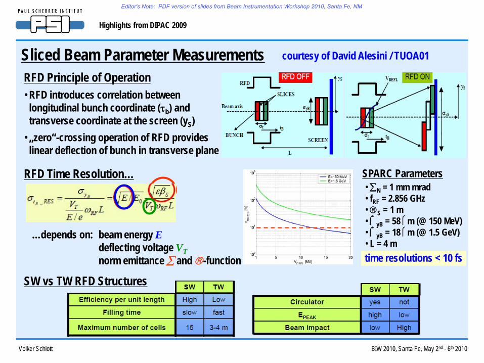
Sliced Beam Parameter Measurements courtesy of David Alesini / TUOA01
RFD Principle of Operation• RFD introduces correlation betweenlongitudinal bunch coordinate (τb) and transverse coordinate at the screen (yS)
• „zero“-crossing operation of RFD provideslinear deflection of bunch in transverse plane
RFD Time Resolution…
…depends on: beam energy Edeflecting voltage VTnorm emittance ∑ and -function
SPARC Parameters• ∑N = 1 mm mrad• fRF = 2.856 GHz• S = 1 m• ⌠yB = 58 m (@ 150 MeV)• ⌠yB = 18 m (@ 1.5 GeV)• L = 4 mtime resolutions < 10 fs
SW vs TW RFD Structures
Editor's Note: PDF version of slides from Beam Instrumentation Workshop 2010, Santa Fe, NM

Volker Schlott BIW 2010, Santa Fe, May 2nd - 6th 2010
Highlights from DIPAC 2009
Sliced Beam Parameter Measurements courtesy of David Alesini / TUOA01
RFD Induced Energy SpreadPanowski-Wenzel theorem directly relates deflecting voltage to longitudinal electric field gradient…:
→ induced energy spread if RFD is operated at „zero“-crossing of deflecting voltage→ energy spread depends linearly on vertical slice size in RFD
Measurements at two different deflecting voltages takes out RFD contribution to sliced energy spread
RFD Measurement: LCLS „Sliced“ Energy Spread @ 135 MeV with Laser Heater off & on
Editor's Note: PDF version of slides from Beam Instrumentation Workshop 2010, Santa Fe, NM

Volker Schlott BIW 2010, Santa Fe, May 2nd - 6th 2010
Highlights from DIPAC 2009
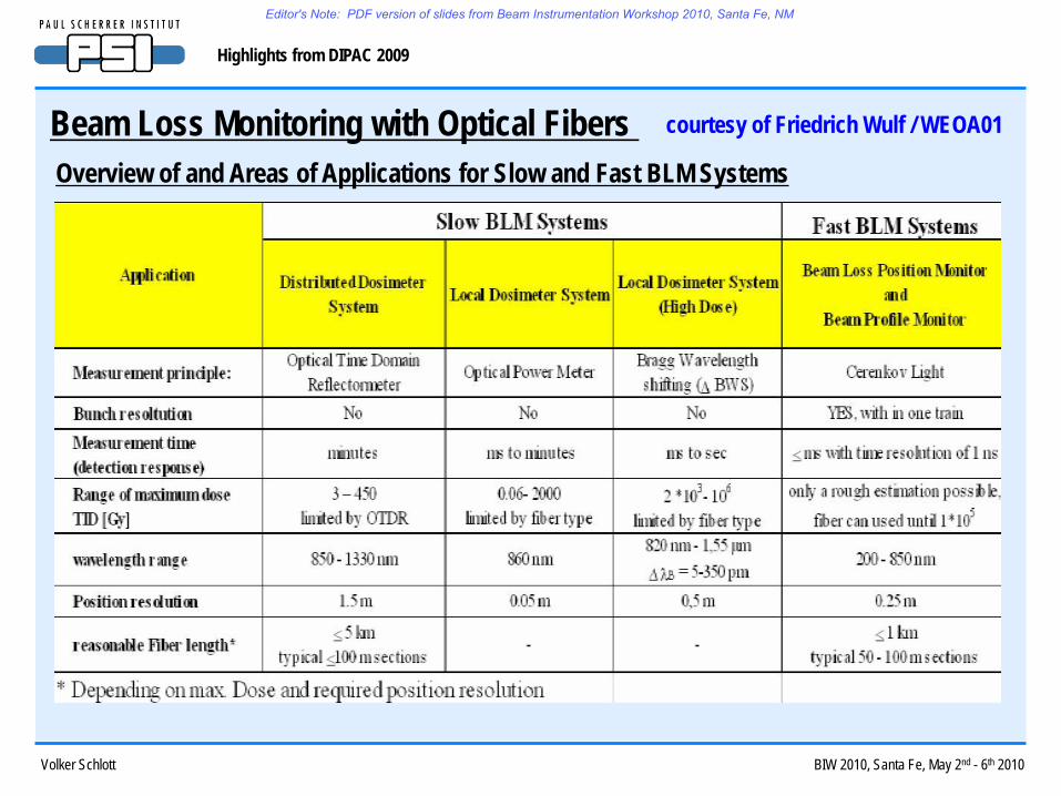
Beam Loss Monitoring with Optical Fibers courtesy of Friedrich Wulf / WEOA01
Optical Fibers as radiation sensors can measure…- the total ionization dose (mGy – kGy even up to MGy) using the effect of radiation induced attenuation- position & dynamic of losses by radiation induced Cerenkov and luminescence light (ms to ns)
Integrating Optical Power Meter – Local and Global Dosimeter Systems
Editor's Note: PDF version of slides from Beam Instrumentation Workshop 2010, Santa Fe, NM

Volker Schlott BIW 2010, Santa Fe, May 2nd - 6th 2010
Highlights from DIPAC 2009
Beam Loss Monitoring with Optical Fibers courtesy of Friedrich Wulf / WEOA01
Fast BLM Systems using Cerenkov Light• radiation resistant, large, multi-core (300 m) fibers• electron with E > 175 keV generate Cerenkov light• PMTs detect Cerenkov light in synch. with the beam• locations calibrated with known BL elements (e.g. OTR)• light velocity in fibers ~ 0.6.c (expanded time scale)
→ beam loss position accuracy ~ 25 cm
Screen Shot of Fast BLM System at FLASH (March 2009) BL Position Monitor (beam transport line)
BLM Arrangement at Undulator Vacuum Chamber
Editor's Note: PDF version of slides from Beam Instrumentation Workshop 2010, Santa Fe, NM
Volker Schlott BIW 2010, Santa Fe, May 2nd - 6th 2010
Highlights from DIPAC 2009
Beam Loss Monitoring with Optical Fibers courtesy of Friedrich Wulf / WEOA01
Overview of and Areas of Applications for Slow and Fast BLM Systems
Editor's Note: PDF version of slides from Beam Instrumentation Workshop 2010, Santa Fe, NM

Volker Schlott BIW 2010, Santa Fe, May 2nd - 6th 2010
Highlights from DIPAC 2009
Instrumentation Requirements for Future Accelerators
- ILC & CLIC luminosity budget: beam position stability & stabilization of large structures: nm scale
a collection of aspects and issues mainly taken from: MOOA01 / WEOA04 / WEOB01 & WEOB03
- Colliders & XFELs: sub-µm BPMs and fast (some 100 kHz BW) position FBs for SC facilitiesreference signal and bunch arrival time stability < 10 fs scale (target: few fs)beam-based longitudinal FBs actively stabilizing accelerator RFbunch length meas. / monitoring of few fs (sub-fs) electron & photon pulseshigh precision instrumentation for few pC operation modes
- FAIR – Facility for Antiproton & Ion Research:various accelerators and storage rings, energy up to 30 GeV/u, high current p and U operationhigh precision (few %), high dynamic range (10 A - 20 A) current measurement up to MHz BWionization profile monitors with 100 m spatial resolution & 100 ns time resolution
What else will / may come…… extreme mechanical stability (sub-nm) and temperature stability / control (0.001°C)… photon (X-ray) beam diagnostics, possibly laser beam diagnostics (gun lasers & seeding)… new challanges in logistics & reliability as facilities become larger & BI-systems more complex…
Editor's Note: PDF version of slides from Beam Instrumentation Workshop 2010, Santa Fe, NM

Volker Schlott BIW 2010, Santa Fe, May 2nd - 6th 2010
Highlights from DIPAC 2009
Final Remarks & Outlookreflects mainly my personal impressions & opinion…!
DIPAC 2009…… showed a largely growing interest in beam instrumentation & diagnostics
→ over 200 participants (~ 150 from Europe / ~ 50 world-wide )→ over 140 contributions ( 24 talks / 118 posters )
… experienced an extremely high quality of oral and poster presentations → almost all submitted during the event allowing to publish the proceedings „in time“
… included already some contributions from neighboring areas (lasers, photons, timing& sync…)→ remember years ago, FPGA developments & some CS-related issues were integrated
… initiated already quite some inspiring discussions in the PC about „the future“→ will / should be discussed with the BIW PC and Asian colleagues→ might lead to closer collaboration with broader scope and efficient information exchange
… caused quite some work for the PC and LOC but was a lot of fun !!!
Thank you for your patience and attention…!!!
Editor's Note: PDF version of slides from Beam Instrumentation Workshop 2010, Santa Fe, NM